EP2075403B1 - Echtzeitmessung von Eigenschaften von Reservoirfluiden - Google Patents
Echtzeitmessung von Eigenschaften von Reservoirfluiden Download PDFInfo
- Publication number
- EP2075403B1 EP2075403B1 EP07124102A EP07124102A EP2075403B1 EP 2075403 B1 EP2075403 B1 EP 2075403B1 EP 07124102 A EP07124102 A EP 07124102A EP 07124102 A EP07124102 A EP 07124102A EP 2075403 B1 EP2075403 B1 EP 2075403B1
- Authority
- EP
- European Patent Office
- Prior art keywords
- sample
- fluid
- analysis
- fluid stream
- sample fluid
- Prior art date
- Legal status (The legal status is an assumption and is not a legal conclusion. Google has not performed a legal analysis and makes no representation as to the accuracy of the status listed.)
- Active
Links
- 239000012530 fluid Substances 0.000 title claims abstract description 200
- 238000005259 measurement Methods 0.000 title claims abstract description 39
- 238000004458 analytical method Methods 0.000 claims abstract description 78
- 238000004891 communication Methods 0.000 claims abstract description 27
- 238000012545 processing Methods 0.000 claims abstract description 18
- 238000000034 method Methods 0.000 claims description 47
- XLYOFNOQVPJJNP-UHFFFAOYSA-N water Substances O XLYOFNOQVPJJNP-UHFFFAOYSA-N 0.000 claims description 22
- 239000000203 mixture Substances 0.000 claims description 11
- 230000008569 process Effects 0.000 claims description 11
- 238000000926 separation method Methods 0.000 claims description 9
- 239000000356 contaminant Substances 0.000 claims description 5
- 239000004215 Carbon black (E152) Substances 0.000 claims description 4
- 238000007599 discharging Methods 0.000 claims description 4
- 229930195733 hydrocarbon Natural products 0.000 claims description 4
- 150000002430 hydrocarbons Chemical class 0.000 claims description 4
- 238000002203 pretreatment Methods 0.000 claims description 4
- 238000003860 storage Methods 0.000 claims description 4
- 239000013043 chemical agent Substances 0.000 claims description 3
- 238000010223 real-time analysis Methods 0.000 abstract description 8
- 239000000523 sample Substances 0.000 description 95
- 239000007789 gas Substances 0.000 description 22
- 238000005070 sampling Methods 0.000 description 22
- 238000012360 testing method Methods 0.000 description 17
- 238000004519 manufacturing process Methods 0.000 description 12
- 239000000126 substance Substances 0.000 description 12
- 230000015572 biosynthetic process Effects 0.000 description 11
- 238000005755 formation reaction Methods 0.000 description 11
- 239000012528 membrane Substances 0.000 description 10
- RWSOTUBLDIXVET-UHFFFAOYSA-N Dihydrogen sulfide Chemical compound S RWSOTUBLDIXVET-UHFFFAOYSA-N 0.000 description 9
- 230000008901 benefit Effects 0.000 description 6
- 238000004364 calculation method Methods 0.000 description 6
- 230000008859 change Effects 0.000 description 5
- 230000008021 deposition Effects 0.000 description 5
- 238000005553 drilling Methods 0.000 description 5
- 239000007788 liquid Substances 0.000 description 5
- 238000012544 monitoring process Methods 0.000 description 5
- 239000000758 substrate Substances 0.000 description 5
- 239000007924 injection Substances 0.000 description 4
- 238000002347 injection Methods 0.000 description 4
- 238000002156 mixing Methods 0.000 description 4
- 230000000704 physical effect Effects 0.000 description 4
- 229910052704 radon Inorganic materials 0.000 description 4
- SYUHGPGVQRZVTB-UHFFFAOYSA-N radon atom Chemical compound [Rn] SYUHGPGVQRZVTB-UHFFFAOYSA-N 0.000 description 4
- 239000007787 solid Substances 0.000 description 4
- 238000011144 upstream manufacturing Methods 0.000 description 4
- 230000000712 assembly Effects 0.000 description 3
- 238000000429 assembly Methods 0.000 description 3
- 239000003153 chemical reaction reagent Substances 0.000 description 3
- QSHDDOUJBYECFT-UHFFFAOYSA-N mercury Chemical compound [Hg] QSHDDOUJBYECFT-UHFFFAOYSA-N 0.000 description 3
- 229910052753 mercury Inorganic materials 0.000 description 3
- 238000005457 optimization Methods 0.000 description 3
- OKTJSMMVPCPJKN-UHFFFAOYSA-N Carbon Chemical compound [C] OKTJSMMVPCPJKN-UHFFFAOYSA-N 0.000 description 2
- 238000011109 contamination Methods 0.000 description 2
- 230000001934 delay Effects 0.000 description 2
- 230000000694 effects Effects 0.000 description 2
- 230000007613 environmental effect Effects 0.000 description 2
- 238000011156 evaluation Methods 0.000 description 2
- 238000001914 filtration Methods 0.000 description 2
- 230000005484 gravity Effects 0.000 description 2
- 230000002209 hydrophobic effect Effects 0.000 description 2
- 239000012535 impurity Substances 0.000 description 2
- 238000009434 installation Methods 0.000 description 2
- 150000002500 ions Chemical class 0.000 description 2
- 239000003921 oil Substances 0.000 description 2
- 239000004576 sand Substances 0.000 description 2
- 238000009491 slugging Methods 0.000 description 2
- 239000000243 solution Substances 0.000 description 2
- 239000011573 trace mineral Substances 0.000 description 2
- 235000013619 trace mineral Nutrition 0.000 description 2
- 238000009736 wetting Methods 0.000 description 2
- 241000894006 Bacteria Species 0.000 description 1
- 229910002651 NO3 Inorganic materials 0.000 description 1
- NHNBFGGVMKEFGY-UHFFFAOYSA-N Nitrate Chemical compound [O-][N+]([O-])=O NHNBFGGVMKEFGY-UHFFFAOYSA-N 0.000 description 1
- 229910000831 Steel Inorganic materials 0.000 description 1
- QAOWNCQODCNURD-UHFFFAOYSA-L Sulfate Chemical compound [O-]S([O-])(=O)=O QAOWNCQODCNURD-UHFFFAOYSA-L 0.000 description 1
- NINIDFKCEFEMDL-UHFFFAOYSA-N Sulfur Chemical compound [S] NINIDFKCEFEMDL-UHFFFAOYSA-N 0.000 description 1
- 238000013459 approach Methods 0.000 description 1
- 238000004590 computer program Methods 0.000 description 1
- 238000005260 corrosion Methods 0.000 description 1
- 230000007797 corrosion Effects 0.000 description 1
- 238000007405 data analysis Methods 0.000 description 1
- 238000007905 drug manufacturing Methods 0.000 description 1
- 238000001035 drying Methods 0.000 description 1
- 239000000975 dye Substances 0.000 description 1
- 239000004931 filters and membranes Substances 0.000 description 1
- 239000008398 formation water Substances 0.000 description 1
- 238000004868 gas analysis Methods 0.000 description 1
- 231100001261 hazardous Toxicity 0.000 description 1
- 230000036541 health Effects 0.000 description 1
- 238000010438 heat treatment Methods 0.000 description 1
- 229910000037 hydrogen sulfide Inorganic materials 0.000 description 1
- 229910003480 inorganic solid Inorganic materials 0.000 description 1
- 230000002427 irreversible effect Effects 0.000 description 1
- 239000013307 optical fiber Substances 0.000 description 1
- 239000002245 particle Substances 0.000 description 1
- 239000012071 phase Substances 0.000 description 1
- 238000005191 phase separation Methods 0.000 description 1
- 231100000572 poisoning Toxicity 0.000 description 1
- 230000000607 poisoning effect Effects 0.000 description 1
- 239000011148 porous material Substances 0.000 description 1
- 238000001556 precipitation Methods 0.000 description 1
- 230000002265 prevention Effects 0.000 description 1
- 210000000664 rectum Anatomy 0.000 description 1
- 230000009467 reduction Effects 0.000 description 1
- 230000002441 reversible effect Effects 0.000 description 1
- 239000013049 sediment Substances 0.000 description 1
- 238000004904 shortening Methods 0.000 description 1
- 241000894007 species Species 0.000 description 1
- 239000010959 steel Substances 0.000 description 1
- 229910052717 sulfur Inorganic materials 0.000 description 1
- 239000011593 sulfur Substances 0.000 description 1
- 229910021653 sulphate ion Inorganic materials 0.000 description 1
- 230000036962 time dependent Effects 0.000 description 1
- 238000012546 transfer Methods 0.000 description 1
- 230000007704 transition Effects 0.000 description 1
- 239000002699 waste material Substances 0.000 description 1
- 238000004065 wastewater treatment Methods 0.000 description 1
Images


Classifications
-
- G—PHYSICS
- G01—MEASURING; TESTING
- G01F—MEASURING VOLUME, VOLUME FLOW, MASS FLOW OR LIQUID LEVEL; METERING BY VOLUME
- G01F1/00—Measuring the volume flow or mass flow of fluid or fluent solid material wherein the fluid passes through a meter in a continuous flow
- G01F1/74—Devices for measuring flow of a fluid or flow of a fluent solid material in suspension in another fluid
-
- G—PHYSICS
- G01—MEASURING; TESTING
- G01N—INVESTIGATING OR ANALYSING MATERIALS BY DETERMINING THEIR CHEMICAL OR PHYSICAL PROPERTIES
- G01N11/00—Investigating flow properties of materials, e.g. viscosity, plasticity; Analysing materials by determining flow properties
-
- G—PHYSICS
- G01—MEASURING; TESTING
- G01N—INVESTIGATING OR ANALYSING MATERIALS BY DETERMINING THEIR CHEMICAL OR PHYSICAL PROPERTIES
- G01N9/00—Investigating density or specific gravity of materials; Analysing materials by determining density or specific gravity
Definitions
- the invention relates to a system end method for real-time, fluid analysis of reservoir fluids during testing and/or production.
- the invention relates to analysing reservoir fluids at surface or subsea.
- samples for analysis are typically taken remotely in a sample receptacle, transported to the location where the analysis instrument lies and then they are introduced into the analyzer for analysis.
- a sample receptacle can be: a pressurised vessel such as a sample bottle, or a bladder or a balloon; and many other types well known in the art. Due to the time taken for manual sampling of fluid phases and analysis of these phases, the number of samples captured and the frequency, i.e. time between samples, the analysis is limited.
- the composition of the reservoir fluid changes with time. Initially the reservoir fluid will be contaminated with drilling and cushion fluids, perforation and formation debris and injected chemicals. When the well is dean, hydrocarbon gas, oil and formation water will flow to surface. The quantity of each phase can change as the flow rate is altered and formation pressure is reduced.
- the document GB 2417913 which is considered the closest prior art, describes a microfluidic separator 110 comprising a porous membrane 108 supported by a microsieve.
- the membrane and sieve are arranged in parallel with the flow 106 of the multiphase mixture and the porous membrane is "wetted" by a portion of the mixture which is transmitted though the pores of the membrane for analysis.
- the membrane may be oleophobic and be arranged to transmit water based solutions or hydrophobic and arranged to transmit oil based solutions or both oleophobic and hydrophobic and arranged to transmit gases. Pressure across the membrane is maintained below capillary breakthrough values for the non-wetting phase and the flow rate though is significantly less than that passing over the membrane thus reducing problems related to cake build up and fouling.
- the separator may be integral to or connected to a microfluidic sample manipulation/analysis chip and one or several valves, possibly in conjunction with a micropump, which may be used to maintain the pressure drop below the non-wetting phase breakthrough pressure.
- Collection channels may also comprise an H-fractal configuration. The main application described relates to the use of the separator in logging while drilling (LWD) or measurement while drilling (MWD) to provide continuous real-time data concerning fluid in a subterranean formation.
- LWD logging while drilling
- MWD measurement while drilling
- the document GB 2 433 273 describes a method for determining a property of formations surrounding an earth borehole being drilled with a drill bit (15) at the end of a drill string, using drilling fluid that flows downward through the drill string, exits through the drill bit, arid returns toward the earth's surface in die annulus between the drill string and the periphery of the borehole.
- the method includes the following steps: obtaining, downhole near the drill bit, a pre-bit sample (211) of the mud in the drill string as it approaches the drill bit; obtaining, downhole near the drill bit, a post-bit sample (212) of the mud in the annulus, entrained with drilled earth formation, after its egression from the drill bit; implementing pre-bit measurements on the pre-bit sample; implementing post-bit measurements on the post-bit sample; and determining a property of the formations from the post-bit measurements and the pre-bit.
- the measurements may be completed downhole, for example using a mass spectrometer.
- the document EP 1 614 465 describes a microfluidic system for performing fluid analysis having: (a) a submersible housing having a fluid analysis means and a power supply to provide power to said system; and (b) a substrate for receiving a fluid sample, having embedded therein a fluid sample inlet, a reagent inlet, a fluid sample outlet, and a mixing region in fluid communication with the fluid sample inlet, the reagent inlet, and the fluid sample outlet, and wherein the substrate includes a fluid drive means for moving the fluid sample through the substrate, and wherein the substrate interconnects with the housing. At least a portion of the fluid analysis means may be embedded in the substrate.
- a first aspect of the invention relates to a system for the analysis of multiphase fluids from a flow line in real time and at flow line conditions comprising: means for directing a sample fluid stream from a flow line to a fluid analysis module; the fluid analysis module comprising a sensor for measuring at least one property of the sample fluid stream; a processor for processing the measurement data from the sensor; and communication means for communicating the processed data to a acquisition unit or computer; a post-treatment module to prepare the sample fluid stream for discharge by returning the sample fluid stream to its original state before analysis.
- the system may contain a separation module for separating the phases of the sample fluid stream.
- the fluid stream may be taken downstream of an existing separator device in which case there will be no need for a separation module.
- the system may also include a pretreatment module for removing contaminants from the sample fluid stream.
- the fluid analysis module can comprise an array of sensors for measuring at least one property of the fluid.
- the sensor of the fluid analysis module can be configured for measuring properties of separated water, oil and/or gas phases of a multiphase fluid.
- Each sensor comprises a sensing means for analyzing at least one fluid property.
- the processor can be part of the fluid analysis module or alternatively the processor can be part of the data acquisition module.
- the sensors comprises the processor for processing the measurement data collected from the sensor and communication means for communication the processed measurement data to a central acquisition unit or computer for further processing.
- each sensor comprises the sensing means
- the processor can process the measurement data from a plurality of sensors and the communication means is also common to a plurality of sensors.
- the sensor having sensing means and comprises a processor for processing the measurement data collected from the sensor, with the communication means being common between a plurality sensors and as such communicating processed measurement data from a plurality of sensors.
- the communication means may typically comprise a data acquisition module to gather the measurement data generated by each sensor after it has been processed by said processor. It may also have a computer system configured to further process the gathered measurement data to generate real-time analysis such as providing data on a physical property of the fluid reservoir in real time.
- a fluid sample outlet is connected to the fluid analysis module to discharge the fluid sample.
- the fluid sample outlet can be in fluid communication with a storage chamber or with the flow line.
- the system is for the analysis of reservoir fluids from a well.
- the present invention system and method are especially suitable for measuring fluid characteristics on the surface or subsea.
- Another aspect of the invention provides a method for the analysis of multiphase fluids in real time and at flow line conditions said method comprising obtaining the sample fluid stream of a fluid from a flow line; directing individual phases of a sample fluid stream to a fluid analysis module comprising an array of sensors; measuring a property of the sample fluid stream using a sensor; processing said measurement; and preparing the sample fluid stream, in a post-treatment module, for dicharge by returning the sample fluid stream to its original state before analysis.
- the method may further comprise gathering processed data from the sensor and further processing the gathered data generating real-time fluid property analysis.
- the analysis may then be transmitted from the site where the analysis takes place to any desirable remote location.
- the fluid analysis module can comprise an array of sensors, each sensors measuring at least one property of the sample fluid stream.
- the method comprises separating the phases of the multiphase fluid into single phase sample streams after obtaining the sample fluid stream from the flow line.
- the method can comprise separating the phases of the multiphase fluid into single phase sample streams before obtaining the sample fluid stream from the flow line.
- the method can further comprise removing contaminants from the sample fluid stream.
- the sample fluid stream can be discharged back into the flow One after measuring a property of the sample fluid stream.
- Chemical agents may be used to measure a property of the sample fluid stream. These chemical agents may then be separated from the sample fluid stream before discharging the sample fluid stream back into the flow line or a container as the case may be for later treatment or disposal.
- the method may comprise storing a sample for further analysis off-line in addition to the real time analysis.
- the method is preferably for measuring fluid properties of any fluid emanating from a hydrocarbon reservoir either during the expiration, testing or production stage of the well.
- the analysis may be transmitted to a surface data acquisition module using wire or wireless communication.
- the method uses the system described above.
- the present invention system and method overcomes some of the drawbacks of existing methods and allow for continuous fluid property analysis of reservoir fluids on site. Some of the advantages of the present invention system and method include:
- the present invention is less costly and more efficient than existing methods. It also eliminates handling of hazardous, and/or pressurized samples thus improving the overall safety of the fluid analysis.
- Figure 1 shows a schematic drawing of the present invention capable of measuring properties of a fluid in a flow line and providing real-time analysis of the results.
- the system is described with reference to analysing fluid from a well and includes a sampling module for obtaining a portion of fluid from a well a pretreatment module, fluid analysis module comprising a sensor array a post treatment module and a data acquisition module.
- Fluid flow from a well is diverted into the system of the invention at flowhead (1) position.
- a choke manifold (2) controls the fluid sample stream.
- the fluid is then directed to a pretreatment module (3). There the multiphase fluid from the well is separated into shingle phases.
- a first gas/liquid separator (4) separates the gas from the oil/water
- a second oil/water separator (5) separates the oil and water into single phases.
- the pre-treatment module can also comprise a unit to remove any solids or impurities that would negatively affect the measurement.
- Each single phase is directed into a sensor assembly (6a, 6b).
- Each sensor assembly can comprises multiple sensors for measuring different properties of the fluid for example, pressure and temperature, density, viscosity.
- the measured data from each of the sensor assemblies is communicated to a data acquisition system (7) for further processing to provide real-time analysis of the fluid flow in a well. This processed data can then be transmitted to a remote location.
- a fluid sample is diverted from the flow line and flowed through a heat exchanger (8) a three phase separator (9) separates the multiphase fluid into a gas phase, liquid, and water phase.
- a sample of the gas phase is directed to a series of gas analysis units (10). These units may be online or offline. The remaining portion the gas sample is burnt off by burners (11).
- a sample of the oil phase and a sample of the water phase are directed to sensor assemblies (6c, 6d) where properties of the oil and water are measured.
- the remaining portion of the oil is diverted to a tank (12) for storage and to burners (11).
- the remaining water is directed to a water treatment unit (13) for eventual disposal.
- the measured data from the online sensors is communicated to a data acquisition module (7) for further processing.
- the system can be during exploration, evaluation, production, extended or cleanup well tests.
- the system may be used for permanent installation, temporary installation or as a portable unit.
- the configuration of the system will depend an the use of the sensor and fluid being analysed.
- the modules may be connected as a multi sensor module configuration as shown in Figure 2 and 3 or as individual sensors for direct measurement of the flowline ( figure 5 ).
- a sampling unit (21) diverts a fluid stream from the main flow line (20) into the sensor system (22).
- the sampling system (21) may also comprise a pre-treatment module which can include a filtering system to remove contaminants from the sample fluid and a separation system to separate the multiphase fluid into single phases.
- the sampling system (21) is connected to the sensor system (22) where a property of the fluid is measured and processed, via a sampling port.
- the sampling port can consist of a valve for flow regulation.
- the sensor system can comprise an array of sensors (23a-c). The sensor will vary depending on the fluid being analysed and are described in further detail below.
- the fluid After the sample fluid has been analysed the fluid is directed away from the sensors to a post treatment module for disposal.
- the measured data can then be communicated to a data acquisition unit (24) where the data is processed generating real-time analysis. This data can then be transmitted from the site of analysis to any remote location.
- the inline sensor assembly 25, as shown in figure 5 can be installed in fluid communication with the flow line (20) for direct measurement of the fluid properties of a fluid. Fluid flows through the sensor assembly (22) via a pre-treatment module (26) where a property of the fluid is measured from the main flowline, before flowing back out the system via a post-treatment module (27). With reference to figure 4 a multiple array of incline sensor assemblies (22a-d) can be used with each sensor in fluid communication with the main flow line (20). A sample of fluid flows through each sensors module where a property of the fluid is measured. The measurement data from each sensor module can then be communicated to a central data acquisition unit (24) where the data from all the sensors is processed generating real-time analysis. This data can then be transmitted from the site of analysis to any remote location.
- the system is configured as a handheld HP sensor assembly ( figure 6 ).
- the handheld sensor assembly (28) is configured to be connected to an existing sampling port where fluid can enter the system (28) via a pretreatment module (26) and a property of the fluid measured by the sensor assembly (22) before fluid flow back out via a post treatment module (27).
- the handheld sensor assembly can also be configured to be connected to bottomhole sampling tools, sample bottles, PVT cells or any other high pressure (HP) source.
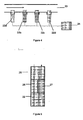
- the system can also be configured to be used with the manual injection of a fluid using a disposable syringe (29), gas bag or connection to any low atmospheric pressure sample source, to deliver a sample fluid stream to the sensor system (22) as shown in Figure 7 .
- samples will be captured from single or multiphase fluid streams using single or multiple sampling probes that selectively sample the required phase.
- the probe may be fixed or have the ability to move and be located at any point across the sample stream.
- the probe may incorporate pressure regulation.
- the location of the sample collector will depend on the purpose of analysis.
- the system can be connected to take samples from wellhead/flow head, up stream/downstream choke manifold, upstream / downstream or directly from multiphase flow meters (i.e.
- PhaseTester separator effluent inlet/outlet streams (gas, oil, water)/ direct, Surge/Gauge/Atmospheric tanks, effluent outlets, inlet and outlet of other well testing vessels (e.g. water treatment unit, heaters, sand filter etc).
- separator effluent inlet/outlet streams gas, oil, water
- Surge/Gauge/Atmospheric tanks effluent outlets
- inlet and outlet of other well testing vessels e.g. water treatment unit, heaters, sand filter etc.
- sampling probe can be located upstream or downstream of the choke manifold, upstrearm/downstream of the multiphase meter or directly from the multiphase meter.
- the system has the advantage of supplying chemical and physical properties of the phases at flow line conditions and In real time which can then be used to improve the calculation of phase flow rates.
- fluid properties density, viscosity
- the pretreatment module allows for sample separation and filtration for the removal of sand/solids with a particulate filter/screen, for the separation of liquid from gas or gas from liquid with a membrane filter, or for the separation of oil from water or water from oil with a membrane filter.
- the pretreatment module can comprise a cyclone, centrifugal separator, or gravity separator to separate and filter particles from the sample. Filters and membranes may be used in series and may be of different grades to increase the purity of the sample phase.
- the module may also comprise pressure relief valve and/or rupture discs and pressure and temperature gauges, sensors and/or transducer to regulate the sample pressure and flow.
- the fluid will be directed to the sensors array.
- any analytical instrument capable of measuring the desired property can be used as a sensor in the array.
- the sensor array includes pipe work and manifolds to connect from the sample pretreatment module to each sensor and each sensor to the sample post-treatment and disposal module.
- a sampling port from the pretreatment module can consist of a valve for flow regulation and a port with threaded connection.
- Each sensor port will include check/non return valves that so when removed the system vall hold pressure and flow is not interrupted.
- Each sensor can act independently although the value obtained by one sensor can be used to calculate or correct values obtained from other sensors, e.g. density from a DV-rod can be used to calculate viscosity from Vibrating wire.
- the number of sensors is not limited and will depend on the situation.
- the system may comprise a plurality of sensors depending on the fluid characteristics to be measured.
- the system may include one or more physical or chemical sensors for measuring inter alia any of the following:
- the sensors may be packaged into a single unit In the fluid analysis module or as individual sensors connected directly to the sample source with a common acquisition unit and software.
- each sensor (30) will consist of four main sections, a measurement section (31), an electronics section (32), a communication section (33) and a power section (34).
- the measurement and electronics sections for each sensor may differ between sensors of the array as they will depend on the physical or chemical property that the sensor is measuring and the processing required to produce the measured property.
- Each sensor can perform onboard calculations of the measured property and thus have calibration coefficients stored on the sensor. In this way each sensor is independent and not reliant on the data acquisition module or software.
- the communication module of the sensor allows each sensors to communicate independently between the sensor and date acquisition module and between the sensor themselves.
- Each sensor can have an independent power supply, such as an onboard battery to enable operation in a wireless mode or as a hand held sensor. They can also be supplied power from an electrical cable or power converted from an optic fire cable from the surface. It is preferred that the electric connections and the communication modules are the same across each sensor in the array.
- Various sensors e.g. pH, alkalinity, ion, may introduce chemicals, reagents or dyes into the sample stream during the analysis process, therefore the system can further comprise a post treatment system.
- Each sensor is in fluid communication with the post-treatment.
- the post treatment system can incorporate scrubbers, for example activated carbon, filters/membranes, centrifugal, cyclone and/or gravity separators to remove all chemicals from the sample that have been added during the analysis process to rectum the sample to its original state before analysis prior to discharging the sample back into the flow or into a storage vessel.
- the sample disposal system can include a high pressure pump to inject the sample into the flow line.
- the fluid sampling stream can be injected back into the main flow line (40) after analysis by the system (41) at the original sampling point (42).
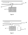
- a fluid sample stream is directed into the system from a fluid inlet (42) and then injected back into the main flow line (40) from the system after analysis via an outlet (43) down stream of the original sampling point as shown in Figure 9 .
- the sensor module (41) can be connected to a waste vessel (44) or tank in which the sample can be stored for later disposal.
- Measured sensor data can be handled in several ways.
- the raw data obtained by the sensor can be processed by a processor located on the sensor with the processed value sent to the data acquisition system. Calibration coefficients and calculations will be stored in the sensor electronics to enable the data to be processed.
- the raw data obtained by the sensor is sent to the data acquisition system and processed by a processor of the data acquisition system whereby the calibration coefficients and calculations will be stored in the data acquisition system.
- the processed data is transmitted to the data acquisition module.
- Communication from the sensors to the data acquisition system can be via electrical cable, optical fibre or wireless i.e. WiFi, blue tooth, radio, infrared. The type of communication used depends an the site/location of the system.
- the process fluid property and chemical data obtained can be used in conjunction with pressure, temperature and flow rate measurements, if required, to:
- This system has the benefits of optimising the clean up, main flow and shut In periods, by lengthening clean up periods to allow the well to clean up fully and shortening clean up flow periods once the well is suitably clean. It allows sampling for lab analysis at the optimum time, for example, sampling after the well is clean and when composition is stable or at equilibrium, eliminates the need of extra sampling flow period and can be used for surface and bottomhole samples.
- the system also allows the flow rate versus choke setting to be optimised. This is critical on gas condensate wells where liquid is accumulating in the well bore and slugging. It ensures the fluid property data delivered at the wellsite is representative.
- the data acquisition module comprises a computer system configured to further process and analysis the data about the fluid to allow for real time trending, well test optimization and well control.
- Data from the multiple sensors is received by the single data acquisition system and processed using a single computer program to allow real time trending, well test optimization and well control.
- the computer system can:
- Data may also be fed into well testing data acquisition software for monitoring fluid property trends in relation to changes in flow/ pressure and temperature conditions.
- the data acquisition module can comprises communication means to transmit the analysis obtained from downhole to the well site surface. From the well site the data can be transmitted by a wellsite user worldwide via a satellite.
- the system can be connected to bottomhole sampling tools used in open hole, cased hole and production. This may be a direct connection or inline during sample transfer.
- a pressurised sample bottle containing samples transferred from bottomhole sampling tools or captured at surface from the wellhead/upstream choke manifold, separator or MFPM. It can be used at the wellsite, mobile lab at the wellsite, remote lab, PVT Labs or any another analytical laboratory. The system can also be used to analyse samples at low or atmospheric pressure.
- the system can be used in surface or subsea applications for monitoring fluid properties during production from the wellhead to the process facility.
- the system can be located at a position (A) downstream of a subsea well head where properties of an individual well can be monitored.
- the system can be located at a position (B) after fluid from two wells is mixed.
- the fluid properties of the co-mingled fluid can be measured at this point and compared to the individual well properties.
- the system is located at a position (C) the riser between the sea floor and platform to monitor changes to the fluid properties as the sample encounters different conditions e.g. reduction in temperature and pressure.
- the system can be used upstream, downstream or directly from a subsea bal-phase meter.
- Fluid properties measured at locations A, B and C are used for flow assurance and solid deposition monitoring.
- the fluid properties are fed into simulation software for the prediction of flow rates, hydrate formation, organic solids deposition (Wax and Asphaltene) and inorganic deposit (scale).
- the performance of gas injection, chemical injection and pipeline heating can be monitored and adjusted based on the change in fluid properties e.g. monitoring fluid density during gas lift operations.
- the system can be located samples taken from the equivalent locations i.e. wellhead, co-mingling/mixing points,
- the system can also be used on production facilities to monitor to chemical and.physical properties.
- the sensor manifold or multiple sensors are connected directly into the flowline are permanently installed or installed on a short term basis.
- Typical applications are measuring fluid properties from individual wells prior to mixing, measuring fluid properties at each stage of separation (before, intermediate and after), before and after treatment vessels i.e. mercury scrubber, H 2 S / CO 2 separation, and measuring fluid properties during well clean up for new or work over wells.
Landscapes
- Physics & Mathematics (AREA)
- Fluid Mechanics (AREA)
- General Physics & Mathematics (AREA)
- Sampling And Sample Adjustment (AREA)
- Engineering & Computer Science (AREA)
- Life Sciences & Earth Sciences (AREA)
- Geology (AREA)
- Mining & Mineral Resources (AREA)
- Geophysics (AREA)
- Environmental & Geological Engineering (AREA)
- General Life Sciences & Earth Sciences (AREA)
- Geochemistry & Mineralogy (AREA)
- Optical Measuring Cells (AREA)
Claims (29)
- System für die Analyse von mehrphasigen Fluiden in Echtzeit und unter Strömungsleitungsbedingungen, das umfasst:Mittel (21), um einen Probenfluidstrom von einer Strömungsleitung (20, 40) zu einem Fluidanalysemodul zu lenken;wobei das Fluidanalysemodul (22) einen Sensor (22a-22d, 23a-23c) umfasst, um wenigstens eine Eigenschaft des Probenfluidstroms zu messen;einen Prozessor, um Messdaten von dem Sensor zu verarbeiten; undKommunikationsmittel, um die verarbeiteten Daten an eine zentrale Erfassungseinheit oder einen zentralen Computer zu übermitteln;dadurch gekennzeichnet, dass das System ferner ein Nachbehandlungsmodul (27) umfasst, um den Probenfluidstrom für die Ausgabe durch Zurückversetzen des Probenfluidstroms in seinen ursprünglichen Zustand vor der Analyse vorzubereiten.
- System nach Anspruch 1, das ein Trennmodul (4, 5, 9) umfasst, um die Phasen des Probenfluidstroms zu trennen.
- System nach den Ansprüchen 1 oder 2, wobei das Fluidanalysemodul (6a-6d) eine Anordnung von Sensoren umfasst.
- System nach den Ansprüchen 1, 2 oder 3, das ein Vorbehandlungsmodul (3, 26) umfasst, um Verunreinigungen aus dem Probenfluidstrom zu entfernen.
- System nach einem der Ansprüche 1-4, wobei der Sensor den Prozessor umfasst, um die von dem Sensor gesammelten Messdaten zu verarbeiten, und die Kommunikationsmittel umfasst, um die verarbeiteten Messdaten zu der zentralen Erfassungseinheit oder dem Computer zu übermitteln.
- System nach einem der Ansprüche 1-4, wobei der Prozessor die Messdaten von mehreren Sensoren verarbeiten kann.
- System nach einem der Ansprüche 1-4, wobei der Sensor den Prozessor zum Verarbeiten der von dem Sensor gesammelten Messdaten umfasst und die Kommunikationsmittel die verarbeiteten Messdaten von mehreren Sensoren übermitteln.
- System nach den Ansprüchen 6 oder 7, wobei die Kommunikationsmittel ein Datenerfassungsmodul (7, 24) umfassen, um die von jedem Sensor erzeugten Messdaten zu sammeln, nachdem sie durch den Prozessor verarbeiteten worden sind.
- System nach Anspruch 7, wobei die Kommunikationsmittel ein Computersystem umfassen, das konfiguriert ist, um die gesammelten Messdaten weiter zu verarbeiten, um eine Echtzeitanalyse zu erzeugen.
- System nach einem der Ansprüche 1 bis 9, das einen Fluidprobenauslass (43) umfasst, der mit dem Fluidanalysemodul verbunden ist, um den Probenfluidstrom auszugeben.
- System nach Anspruch 10, wobei der Fluidprobenauslass (43) mit einer Speicherkammer (44) in einer Fluidkommunikation steht.
- System nach Anspruch 10, wobei der Fluidprobenauslass (43) mit der Strömungsleitung in einer Fluidkommunikation steht.
- System nach einem der Ansprüche 1-12, das eine Probenvorrichtung (29) umfasst, um Proben für eine weitere Analyse off-line zu nehmen.
- System nach einem der Ansprüche 1-13 für die Analyse von Lagerstättenfluiden von einem Bohrloch.
- Verfahren für die Analyse mehrphasiger Fluide in Echtzeit und unter Strömungsleitungsbedingungen, das umfasst:Erhalten eines Probenfluidstroms von einer Strömungsleitung (20, 40);Lenken einer einzelnen Phase des Probenfluidstroms zu einem Fluidanalysemodul (22), das einen Sensor (22a-22d, 23a-23c) umfasst, um wenigstens eine Eigenschaft des Probenfluidstroms zu messen;Messen einer Eigenschaft des Probenfluidstroms unter Verwendung des Sensors; undVerarbeiten der Messungen;dadurch gekennzeichnet, dass das Verfahren ferner das Vorbereiten des Probenfluidstroms in einem Nachbehandlungsmodul umfasst, um es durch Zurückführen des Probenfluidstroms in seinen ursprünglichen Zustand vor der Analyse auszugeben.
- Verfahren nach Anspruch 15, das ferner das Sammeln verarbeiteter Daten von den Sensoren und das weitere Verarbeiten der gesammelten Daten umfasst, um eine Echtzeit-Fluideigenschaftsanalyse zu erzeugen.
- Verfahren nach Anspruch 16, das das Senden der Analyse an einen entfernten Ort umfasst.
- Verfahren nach den Ansprüchen 15, 16 oder 17, wobei das Fluidanalysemodul eine Anordnung von Sensoren umfasst, wobei jeder Sensor wenigstens eine Eigenschaft des Probenfluidstroms misst:
- Verfahren nach einem der Ansprüche 15-18, das das Trennen der Phasen des mehrphasigen Fluids in einen Einzelphasen-Probenfluidstrom umfasst, nachdem der Probenftuidstrom von der Strömungsleitung (20, 40) erhalten worden ist.
- Verfahren nach einem der Ansprüche 15-18, das das Trennen der Phasen des mehrphasigen Fluids in einen Einzelphasen-Probenfluidstrom umfasst, bevor der Probenfluidstrom von der Strömungsleitung (20, 40) erhalten wird.
- Verfahren nach einem der Ansprüche 15-20, das das Entfernen von Verunreinigungen aus dem Probenfluidstrom umfasst.
- Verfahren nach einem der Ansprüche 15-21, das das Ausgeben des Probenfluidstroms zurück in die Strömungsleitung (20, 40) nach dem Messen einer Eigenschaft des Probenfluidstroms umfasst.
- Verfahren nach einem der Ansprüche 15-22, das das Trennen chemischer Stoffe, die verwendet werden, um eine Eigenschaft des Probenfluidstroms zu messen, vor der Ausgabe des Probenfluidstroms zurück in die Strömungsleitung (20, 40) umfasst.
- Verfahren nach einem der Ansprüche 15-22, das das Speichern des Probenfluidstroms in einem Behälter (44) für eine spätere Behandlung oder Entsorgung umfasst.
- Verfahren nach einem der Ansprüche 15-24, das das Halten einer Probe des Probenfluidstroms für eine weitere, off-line Analyse umfasst.
- Verfahren nach einem der Ansprüche 15-25 zum Messen der Fluideigenschaften eines mehrphasigen Fluids von einer Kohlenwasserstoff-Lagerstätte.
- Verfahren nach Anspruch 26, das das Trennen des mehrphasigen Gemisches in eine Ölphase, eine Wasserphase und eine Gasphase umfasst.
- Verfahren nach einem der Ansprüche 15-27, das unter Verwendung des Systems nach einem der Ansprüche 1-14 ausgeführt wird
- Verfahren nach Anspruch 28, das das Auslegen des Systems unter Wasser und das Senden der Analyse zu einem Oberflächen-Datenerfassungsmodul (7, 24) umfasst.
Priority Applications (6)
| Application Number | Priority Date | Filing Date | Title |
|---|---|---|---|
| AT07124102T ATE491862T1 (de) | 2007-12-27 | 2007-12-27 | Echtzeitmessung von eigenschaften von reservoirfluiden |
| DK07124102.0T DK2075403T3 (da) | 2007-12-27 | 2007-12-27 | Realtidsmåling af resevoirfluiders egenskaber |
| DE602007011308T DE602007011308D1 (de) | 2007-12-27 | 2007-12-27 | Echtzeitmessung von Eigenschaften von Reservoirfluiden |
| EP07124102A EP2075403B1 (de) | 2007-12-27 | 2007-12-27 | Echtzeitmessung von Eigenschaften von Reservoirfluiden |
| US12/810,924 US9696193B2 (en) | 2007-12-27 | 2008-12-24 | Real-time measurement of reservoir fluid properties |
| PCT/EP2008/011111 WO2009083243A1 (en) | 2007-12-27 | 2008-12-24 | Real-time measurement of reservoir fluid properties |
Applications Claiming Priority (1)
| Application Number | Priority Date | Filing Date | Title |
|---|---|---|---|
| EP07124102A EP2075403B1 (de) | 2007-12-27 | 2007-12-27 | Echtzeitmessung von Eigenschaften von Reservoirfluiden |
Publications (2)
| Publication Number | Publication Date |
|---|---|
| EP2075403A1 EP2075403A1 (de) | 2009-07-01 |
| EP2075403B1 true EP2075403B1 (de) | 2010-12-15 |
Family
ID=39434041
Family Applications (1)
| Application Number | Title | Priority Date | Filing Date |
|---|---|---|---|
| EP07124102A Active EP2075403B1 (de) | 2007-12-27 | 2007-12-27 | Echtzeitmessung von Eigenschaften von Reservoirfluiden |
Country Status (6)
| Country | Link |
|---|---|
| US (1) | US9696193B2 (de) |
| EP (1) | EP2075403B1 (de) |
| AT (1) | ATE491862T1 (de) |
| DE (1) | DE602007011308D1 (de) |
| DK (1) | DK2075403T3 (de) |
| WO (1) | WO2009083243A1 (de) |
Cited By (1)
| Publication number | Priority date | Publication date | Assignee | Title |
|---|---|---|---|---|
| CN107179398A (zh) * | 2017-06-23 | 2017-09-19 | 零点创新科技有限公司 | 加油加气站油气浓度检测装置及其分析预警方法 |
Families Citing this family (47)
| Publication number | Priority date | Publication date | Assignee | Title |
|---|---|---|---|---|
| NO329763B1 (no) * | 2009-05-09 | 2010-12-13 | Tool Tech As | Fremgangsmate for provetaking og analyse av produksjon fra en undervannsbronn for maling av saltinnhold i produsert vann samt volumforhold mellom vaeskefraksjonene |
| EP2446117B1 (de) * | 2009-06-25 | 2019-09-11 | OneSubsea IP UK Limited | Probenrutsche für unterseebohrlöcher |
| US8548743B2 (en) | 2009-07-10 | 2013-10-01 | Schlumberger Technology Corporation | Method and apparatus to monitor reformation and replacement of CO2/CH4 gas hydrates |
| WO2011119479A1 (en) * | 2010-03-23 | 2011-09-29 | Shell Oil Company | Mass flow meter |
| GB2483671B (en) | 2010-09-15 | 2016-04-13 | Managed Pressure Operations | Drilling system |
| NO336049B1 (no) | 2010-10-22 | 2015-04-27 | Seabox As | Teknisk system, fremgangsmåte og anvendelse for online måling og overvåking av partikkelinnholdet i en injeksjonsvannstrøm i en undervannsledning |
| US20120158337A1 (en) * | 2010-12-17 | 2012-06-21 | Anil Singh | Method and Integrated System for Improving Data and Service Quality with Respect to Measurement and Analysis of Reservoir Fluid Samples |
| CA2822564C (en) * | 2011-02-11 | 2016-01-05 | Schlumberger Canada Limited | Microfluidic system and method for performing a flash separation of a reservoir fluid sample |
| AU2012296868B2 (en) * | 2011-08-18 | 2015-08-27 | Shell Internationale Research Maatschappij B.V. | System and method for producing a hydrocarbon product stream from a hydrocarbon well stream, and a hydrocarbon well stream separation tank |
| US9618427B2 (en) * | 2012-03-02 | 2017-04-11 | Schlumberger Technology Corporation | Sampling separation module for subsea or surface application |
| US9442218B2 (en) * | 2012-04-17 | 2016-09-13 | Selman and Associates, Ltd. | Gas trap with gas analyzer system for continuous gas analysis |
| DE102012104025A1 (de) * | 2012-05-08 | 2013-11-14 | Endress + Hauser Conducta Gesellschaft für Mess- und Regeltechnik mbH + Co. KG | Sensoreinheit zur Bestimmung einer Messgröße eines Messstoffs |
| RU2497083C1 (ru) * | 2012-06-09 | 2013-10-27 | Шлюмберже Текнолоджи Б.В. | Способ оценки термодинамического равновесия газожидкостной смеси при проведении фильтрационных экспериментов |
| EP2677115B1 (de) * | 2012-06-22 | 2019-01-02 | Openfield | Prognostisches Flussversicherungsbeurteilungsverfahren und -system |
| US8935100B2 (en) * | 2012-12-18 | 2015-01-13 | NeoTek Energy, Inc. | System and method for production reservoir and well management using continuous chemical measurement |
| WO2015026722A1 (en) * | 2013-08-19 | 2015-02-26 | Schlumberger Canada Limited | Water treatment system for treating water from oil production streams |
| US10570731B2 (en) * | 2013-10-03 | 2020-02-25 | Halliburton Energy Services, Inc. | Solvent extraction and analysis of formation fluids from formation solids at a well site |
| WO2016028409A1 (en) | 2014-08-21 | 2016-02-25 | Exxonmobil Upstream Research Company | Gas lift optimization employing data obtained from surface mounted sensors |
| NO343025B1 (no) * | 2014-12-23 | 2018-10-08 | Resman As | Fremgangsmåte og apparat for online monitorering av tracere |
| US10287869B2 (en) * | 2015-01-27 | 2019-05-14 | Cameron International Corporation | Fluid monitoring systems and methods |
| US10125600B2 (en) | 2015-06-05 | 2018-11-13 | Baker Hughes, A Ge Company, Llc | System and method for sensing fluids downhole |
| US10612374B2 (en) * | 2015-06-10 | 2020-04-07 | Halliburton Energy Services, Inc. | Apparatus and methods to manage wellbore fluid properties |
| GB2591057B (en) * | 2015-06-10 | 2022-01-12 | Halliburton Energy Services Inc | Apparatus and methods to manage wellbore fluid properties |
| GB2591058B (en) * | 2015-06-10 | 2022-01-12 | Halliburton Energy Services Inc | Apparatus and methods to manage wellbore fluid properties |
| US10551367B2 (en) * | 2015-06-25 | 2020-02-04 | Saudi Arabian Oil Company | Geochemical water analysis element concentration prediction for oilfield waters |
| EP3356736B1 (de) | 2015-09-28 | 2022-08-10 | Services Pétroliers Schlumberger | Überwachungs- und steuerungssysteme für einen brenner |
| US10273791B2 (en) * | 2015-11-02 | 2019-04-30 | General Electric Company | Control system for a CO2 fracking system and related system and method |
| AU2016412929B2 (en) | 2016-06-28 | 2023-02-02 | Schlumberger Technology B.V. | Surface well testing systems and methods |
| CN106248524B (zh) * | 2016-08-10 | 2019-04-26 | 湖南镭目科技有限公司 | 一种转炉炉渣粘度在线监测系统及方法 |
| RU2659323C2 (ru) * | 2016-10-17 | 2018-06-29 | Общество С Ограниченной Ответственностью "Газпром Трансгаз Краснодар" | Способ гравиметрического определения механических примесей в природном газе путём осаждения частиц из природного газа |
| US10684154B2 (en) * | 2016-12-12 | 2020-06-16 | Ventbuster Holdings Inc. | Gas meter and associated methods |
| RU2726778C1 (ru) * | 2017-02-03 | 2020-07-15 | Ресман Ас | Закачивание целевого индикатора с онлайн-датчиком |
| US10859549B2 (en) * | 2017-02-07 | 2020-12-08 | Microsilicon, Inc. | Online monitoring of production processes using electron paramagnetic resonance (EPR) |
| CN106761656A (zh) * | 2017-02-28 | 2017-05-31 | 中国石油集团川庆钻探工程有限公司长庆井下技术作业公司 | 一种分离器 |
| US11365626B2 (en) * | 2017-03-01 | 2022-06-21 | Proptester, Inc. | Fluid flow testing apparatus and methods |
| US20210140809A1 (en) * | 2017-06-02 | 2021-05-13 | Inventrom Private Limited | System and method for monitoring level of material stored in receptacles |
| WO2018236402A1 (en) * | 2017-06-23 | 2018-12-27 | Fmc Technologies, Inc. | SEPARATION SYSTEM |
| US11002111B2 (en) * | 2018-12-19 | 2021-05-11 | Saudi Arabian Oil Company | Hydrocarbon flowline corrosion inhibitor overpressure protection |
| EP3680658B1 (de) * | 2019-01-11 | 2023-05-10 | Grant Prideco, Inc. | System zur optimierung der kohlenwasserstoffproduktion |
| US11098811B2 (en) * | 2019-02-27 | 2021-08-24 | Saudi Arabian Oil Company | Bonnet vent attachment |
| US10871762B2 (en) | 2019-03-07 | 2020-12-22 | Saudi Arabian Oil Company | Real time analysis of fluid properties for drilling control |
| US11168534B2 (en) | 2019-11-06 | 2021-11-09 | Saudi Arabian Oil Company | Downhole crossflow containment tool |
| CN111794729B (zh) * | 2020-08-13 | 2022-09-30 | 重庆科技学院 | 一种基于定产量生产的含硫气井生产模拟装置及方法 |
| US11833449B2 (en) | 2021-09-22 | 2023-12-05 | Saudi Arabian Oil Company | Method and device for separating and measuring multiphase immiscible fluid mixtures |
| US11833445B2 (en) | 2021-09-22 | 2023-12-05 | Saudi Arabian Oil Company | Method and device for separating and measuring multiphase immiscible fluid mixtures using an improved analytical cell |
| US11761945B2 (en) | 2021-09-22 | 2023-09-19 | Saudi Arabian Oil Company | Water analysis unit of a system for separating and analyzing a multiphase immiscible fluid mixture and corresponding method |
| CN117108272B (zh) * | 2023-10-23 | 2024-02-06 | 东北石油大学 | 油气储盖层中三种特征毛细管压力一体测试装置和方法 |
Family Cites Families (40)
| Publication number | Priority date | Publication date | Assignee | Title |
|---|---|---|---|---|
| US5689540A (en) * | 1996-10-11 | 1997-11-18 | Schlumberger Technology Corporation | X-ray water fraction meter |
| FR2772126B1 (fr) | 1997-12-05 | 2000-01-07 | Schlumberger Services Petrol | Procede et dispositif de prelevement isocinetique d'echantillons d'un fluide s'ecoulant dans une tuyauterie |
| US6758090B2 (en) | 1998-06-15 | 2004-07-06 | Schlumberger Technology Corporation | Method and apparatus for the detection of bubble point pressure |
| GB2363809B (en) * | 2000-06-21 | 2003-04-02 | Schlumberger Holdings | Chemical sensor for wellbore applications |
| US6578405B2 (en) | 2001-09-25 | 2003-06-17 | Schlumberger Technology Corporation | Gas seep detection |
| US8612193B2 (en) | 2002-05-21 | 2013-12-17 | Schlumberger Technology Center | Processing and interpretation of real-time data from downhole and surface sensors |
| GB2395555B (en) | 2002-11-22 | 2005-10-12 | Schlumberger Holdings | Apparatus and method of analysing downhole water chemistry |
| US7201841B2 (en) * | 2003-02-05 | 2007-04-10 | Water Visions International, Inc. | Composite materials for fluid treatment |
| US7393690B2 (en) * | 2003-05-06 | 2008-07-01 | Thrombodyne, Inc. | Systems and methods for measuring fluid properties |
| GB2406386B (en) | 2003-09-29 | 2007-03-07 | Schlumberger Holdings | Isokinetic sampling |
| US7379819B2 (en) | 2003-12-04 | 2008-05-27 | Schlumberger Technology Corporation | Reservoir sample chain-of-custody |
| US7108069B2 (en) * | 2004-04-23 | 2006-09-19 | Offshore Systems, Inc. | Online thermal and watercut management |
| US7243718B2 (en) | 2004-06-18 | 2007-07-17 | Schlumberger Technology Corporation | Methods for locating formation fractures and monitoring well completion using streaming potential transients information |
| US7799278B2 (en) | 2004-07-06 | 2010-09-21 | Schlumberger Technology Corporation | Microfluidic system for chemical analysis |
| US7575681B2 (en) | 2004-07-06 | 2009-08-18 | Schlumberger Technology Corporation | Microfluidic separator |
| EP1617202B1 (de) | 2004-07-13 | 2009-09-23 | Services Petroliers Schlumberger | Detektor zum Unterscheiden von Phasen in einer Multi-Phasen Flüssigkeitsmischung |
| JP2008510130A (ja) * | 2004-08-13 | 2008-04-03 | コーニンクレッカ フィリップス エレクトロニクス エヌ ヴィ | ソリッドステート検出器パッケージングの技術 |
| ATE366412T1 (de) | 2004-10-07 | 2007-07-15 | Schlumberger Technology Bv | Probenentnahmegerät |
| US7474969B2 (en) * | 2004-11-01 | 2009-01-06 | Shell Oil Company | Method and system for production metering of oil wells |
| US7305306B2 (en) | 2005-01-11 | 2007-12-04 | Schlumberger Technology Corporation | System and methods of deriving fluid properties of downhole fluids and uncertainty thereof |
| WO2007008793A2 (en) * | 2005-07-11 | 2007-01-18 | Phase Dynamics | Multiphase fluid characterization |
| CA2557380C (en) * | 2005-08-27 | 2012-09-25 | Schlumberger Canada Limited | Time-of-flight stochastic correlation measurements |
| US7658226B2 (en) | 2005-11-02 | 2010-02-09 | Schlumberger Technology Corporation | Method of monitoring fluid placement during stimulation treatments |
| GB2432425B (en) | 2005-11-22 | 2008-01-09 | Schlumberger Holdings | Isokinetic sampling method and system for multiphase flow from subterranean wells |
| US7384453B2 (en) | 2005-12-07 | 2008-06-10 | Schlumberger Technology Corporation | Self-contained chromatography system |
| GB2433315B (en) * | 2005-12-17 | 2008-07-09 | Schlumberger Holdings | Method and system for analyzing multi-phase mixtures |
| US7458257B2 (en) | 2005-12-19 | 2008-12-02 | Schlumberger Technology Corporation | Downhole measurement of formation characteristics while drilling |
| US7402424B2 (en) | 2006-02-01 | 2008-07-22 | Schlumberger Technology Corporation | Spectroscopic pH measurement at high-temperature and/or high-pressure |
| WO2007113636A2 (en) * | 2006-04-03 | 2007-10-11 | Nokia Corporation | Multimedia session domain selection |
| EP1862781A1 (de) | 2006-05-31 | 2007-12-05 | Services Pétroliers Schlumberger | Vorrichtung und Verfahren zur Bestimmung eines charakteristischen Verhältnisses und eines das charakteristische Verhältnis beeinflussenden Parameters eines Mehrphasen-Fluidgemisches |
| US20080135237A1 (en) | 2006-06-01 | 2008-06-12 | Schlumberger Technology Corporation | Monitoring injected nonhydrocarbon and nonaqueous fluids through downhole fluid analysis |
| US7886825B2 (en) | 2006-09-18 | 2011-02-15 | Schlumberger Technology Corporation | Formation fluid sampling tools and methods utilizing chemical heating |
| JP4981142B2 (ja) | 2006-10-25 | 2012-07-18 | シュルンベルジェ ホールディングス リミテッド | Gc×gcを用いた炭化水素サンプル中の汚染の高精度評価 |
| US7600413B2 (en) | 2006-11-29 | 2009-10-13 | Schlumberger Technology Corporation | Gas chromatography system architecture |
| US7637151B2 (en) | 2006-12-19 | 2009-12-29 | Schlumberger Technology Corporation | Enhanced downhole fluid analysis |
| US7658092B2 (en) | 2006-12-22 | 2010-02-09 | Schlumberger Technology Corporation | Heat switch for chromatographic system and method of operation |
| GB2447908B (en) | 2007-03-27 | 2009-06-03 | Schlumberger Holdings | System and method for spot check analysis or spot sampling of a multiphase mixture flowing in a pipeline |
| US8028562B2 (en) | 2007-12-17 | 2011-10-04 | Schlumberger Technology Corporation | High pressure and high temperature chromatography |
| US20090158820A1 (en) | 2007-12-20 | 2009-06-25 | Schlumberger Technology Corporation | Method and system for downhole analysis |
| US8250904B2 (en) | 2007-12-20 | 2012-08-28 | Schlumberger Technology Corporation | Multi-stage injector for fluid analysis |
-
2007
- 2007-12-27 DK DK07124102.0T patent/DK2075403T3/da active
- 2007-12-27 DE DE602007011308T patent/DE602007011308D1/de active Active
- 2007-12-27 AT AT07124102T patent/ATE491862T1/de not_active IP Right Cessation
- 2007-12-27 EP EP07124102A patent/EP2075403B1/de active Active
-
2008
- 2008-12-24 US US12/810,924 patent/US9696193B2/en active Active
- 2008-12-24 WO PCT/EP2008/011111 patent/WO2009083243A1/en active Application Filing
Cited By (2)
| Publication number | Priority date | Publication date | Assignee | Title |
|---|---|---|---|---|
| CN107179398A (zh) * | 2017-06-23 | 2017-09-19 | 零点创新科技有限公司 | 加油加气站油气浓度检测装置及其分析预警方法 |
| CN107179398B (zh) * | 2017-06-23 | 2019-09-20 | 零点创新科技有限公司 | 加油加气站油气浓度检测分析预警方法 |
Also Published As
| Publication number | Publication date |
|---|---|
| DE602007011308D1 (de) | 2011-01-27 |
| EP2075403A1 (de) | 2009-07-01 |
| DK2075403T3 (da) | 2011-03-21 |
| ATE491862T1 (de) | 2011-01-15 |
| US9696193B2 (en) | 2017-07-04 |
| US20110040501A1 (en) | 2011-02-17 |
| WO2009083243A1 (en) | 2009-07-09 |
Similar Documents
| Publication | Publication Date | Title |
|---|---|---|
| EP2075403B1 (de) | Echtzeitmessung von Eigenschaften von Reservoirfluiden | |
| RU2168011C2 (ru) | Автоматизированная система испытания скважин и способ ее эксплуатации | |
| EP1877646B1 (de) | Verfahren und vorrichtung zur bohrlochfluidanalyse | |
| US7788972B2 (en) | Method of downhole characterization of formation fluids, measurement controller for downhole characterization of formation fluids, and apparatus for downhole characterization of formation fluids | |
| CA2789718A1 (en) | Method and system for measurement of reservoir fluid properties | |
| US20130319104A1 (en) | Methods and systems of collecting and analyzing drilling fluids in conjunction with drilling operations | |
| EP3814772B1 (de) | Verfahren zur online-überwachung der wasserqualität und der partikelentnahme in einem trinkwasserverteilungsnetz | |
| GB2377952A (en) | Fluid sampling and sensor device | |
| US8342004B2 (en) | Gas analyzer | |
| NO325099B1 (no) | Anordning for nedihulls kjemisk analyse av bronnfluider | |
| WO2011132040A2 (en) | Utilisation of tracers in hydrocarbon wells | |
| WO2020112131A1 (en) | Mud filtrate property measurement for downhole contamination assessment | |
| AU2009259934B2 (en) | Optical determination and reporting of fluid properties | |
| US11320347B1 (en) | Portable, high temperature, heavy oil well test unit with automatic multi sampling system | |
| US8360143B2 (en) | Method of determining end member concentrations | |
| US8898018B2 (en) | Methods and systems for hydrocarbon production | |
| MX2014008639A (es) | Aparatos, sistemas y metodos acondicionadores de sensor. | |
| EP1629176B1 (de) | Online-zusammensetzungszuordnung | |
| CN101353960A (zh) | 探井试油连续计量装置 | |
| CA2728505C (en) | Optical determination and reporting of fluid properties | |
| Frédérick et al. | Deep aquifer sampling and the use of ball check-valves systems | |
| WO2013122477A1 (en) | Apparatus and method for well testing | |
| CN114764092B (zh) | 一种结垢模拟装置及结垢模拟方法 | |
| US20240159726A1 (en) | Isotopic monitoring of reservoir water | |
| Betancourt et al. | Chain of Custody for Samples of Live Crude Oil Using Visible–Near-Infrared Spectroscopy |
Legal Events
| Date | Code | Title | Description |
|---|---|---|---|
| PUAI | Public reference made under article 153(3) epc to a published international application that has entered the european phase |
Free format text: ORIGINAL CODE: 0009012 |
|
| AK | Designated contracting states |
Kind code of ref document: A1 Designated state(s): AT BE BG CH CY CZ DE DK EE ES FI FR GB GR HU IE IS IT LI LT LU LV MC MT NL PL PT RO SE SI SK TR |
|
| AX | Request for extension of the european patent |
Extension state: AL BA HR MK RS |
|
| 17P | Request for examination filed |
Effective date: 20091125 |
|
| 17Q | First examination report despatched |
Effective date: 20091221 |
|
| AKX | Designation fees paid |
Designated state(s): AT BE BG CH CY CZ DE DK EE ES FI FR GB GR HU IE IS IT LI LT LU LV MC MT NL PL PT RO SE SI SK TR |
|
| GRAP | Despatch of communication of intention to grant a patent |
Free format text: ORIGINAL CODE: EPIDOSNIGR1 |
|
| GRAS | Grant fee paid |
Free format text: ORIGINAL CODE: EPIDOSNIGR3 |
|
| GRAA | (expected) grant |
Free format text: ORIGINAL CODE: 0009210 |
|
| AK | Designated contracting states |
Kind code of ref document: B1 Designated state(s): AT BE BG CH CY CZ DE DK EE ES FI FR GB GR HU IE IS IT LI LT LU LV MC MT NL PL PT RO SE SI SK TR |
|
| REG | Reference to a national code |
Ref country code: GB Ref legal event code: FG4D Ref country code: CH Ref legal event code: EP |
|
| REG | Reference to a national code |
Ref country code: IE Ref legal event code: FG4D |
|
| REF | Corresponds to: |
Ref document number: 602007011308 Country of ref document: DE Date of ref document: 20110127 Kind code of ref document: P |
|
| REG | Reference to a national code |
Ref country code: DK Ref legal event code: T3 |
|
| REG | Reference to a national code |
Ref country code: NL Ref legal event code: VDEP Effective date: 20101215 |
|
| PG25 | Lapsed in a contracting state [announced via postgrant information from national office to epo] |
Ref country code: LT Free format text: LAPSE BECAUSE OF FAILURE TO SUBMIT A TRANSLATION OF THE DESCRIPTION OR TO PAY THE FEE WITHIN THE PRESCRIBED TIME-LIMIT Effective date: 20101215 |
|
| LTIE | Lt: invalidation of european patent or patent extension |
Effective date: 20101215 |
|
| PG25 | Lapsed in a contracting state [announced via postgrant information from national office to epo] |
Ref country code: LV Free format text: LAPSE BECAUSE OF FAILURE TO SUBMIT A TRANSLATION OF THE DESCRIPTION OR TO PAY THE FEE WITHIN THE PRESCRIBED TIME-LIMIT Effective date: 20101215 Ref country code: AT Free format text: LAPSE BECAUSE OF FAILURE TO SUBMIT A TRANSLATION OF THE DESCRIPTION OR TO PAY THE FEE WITHIN THE PRESCRIBED TIME-LIMIT Effective date: 20101215 Ref country code: NL Free format text: LAPSE BECAUSE OF FAILURE TO SUBMIT A TRANSLATION OF THE DESCRIPTION OR TO PAY THE FEE WITHIN THE PRESCRIBED TIME-LIMIT Effective date: 20101215 Ref country code: BG Free format text: LAPSE BECAUSE OF FAILURE TO SUBMIT A TRANSLATION OF THE DESCRIPTION OR TO PAY THE FEE WITHIN THE PRESCRIBED TIME-LIMIT Effective date: 20110315 Ref country code: CY Free format text: LAPSE BECAUSE OF FAILURE TO SUBMIT A TRANSLATION OF THE DESCRIPTION OR TO PAY THE FEE WITHIN THE PRESCRIBED TIME-LIMIT Effective date: 20101215 Ref country code: SI Free format text: LAPSE BECAUSE OF FAILURE TO SUBMIT A TRANSLATION OF THE DESCRIPTION OR TO PAY THE FEE WITHIN THE PRESCRIBED TIME-LIMIT Effective date: 20101215 Ref country code: SE Free format text: LAPSE BECAUSE OF FAILURE TO SUBMIT A TRANSLATION OF THE DESCRIPTION OR TO PAY THE FEE WITHIN THE PRESCRIBED TIME-LIMIT Effective date: 20101215 Ref country code: FI Free format text: LAPSE BECAUSE OF FAILURE TO SUBMIT A TRANSLATION OF THE DESCRIPTION OR TO PAY THE FEE WITHIN THE PRESCRIBED TIME-LIMIT Effective date: 20101215 |
|
| PG25 | Lapsed in a contracting state [announced via postgrant information from national office to epo] |
Ref country code: MC Free format text: LAPSE BECAUSE OF NON-PAYMENT OF DUE FEES Effective date: 20101231 Ref country code: CZ Free format text: LAPSE BECAUSE OF FAILURE TO SUBMIT A TRANSLATION OF THE DESCRIPTION OR TO PAY THE FEE WITHIN THE PRESCRIBED TIME-LIMIT Effective date: 20101215 Ref country code: GR Free format text: LAPSE BECAUSE OF FAILURE TO SUBMIT A TRANSLATION OF THE DESCRIPTION OR TO PAY THE FEE WITHIN THE PRESCRIBED TIME-LIMIT Effective date: 20110316 Ref country code: EE Free format text: LAPSE BECAUSE OF FAILURE TO SUBMIT A TRANSLATION OF THE DESCRIPTION OR TO PAY THE FEE WITHIN THE PRESCRIBED TIME-LIMIT Effective date: 20101215 Ref country code: PT Free format text: LAPSE BECAUSE OF FAILURE TO SUBMIT A TRANSLATION OF THE DESCRIPTION OR TO PAY THE FEE WITHIN THE PRESCRIBED TIME-LIMIT Effective date: 20110415 Ref country code: BE Free format text: LAPSE BECAUSE OF FAILURE TO SUBMIT A TRANSLATION OF THE DESCRIPTION OR TO PAY THE FEE WITHIN THE PRESCRIBED TIME-LIMIT Effective date: 20101215 Ref country code: IS Free format text: LAPSE BECAUSE OF FAILURE TO SUBMIT A TRANSLATION OF THE DESCRIPTION OR TO PAY THE FEE WITHIN THE PRESCRIBED TIME-LIMIT Effective date: 20110415 Ref country code: ES Free format text: LAPSE BECAUSE OF FAILURE TO SUBMIT A TRANSLATION OF THE DESCRIPTION OR TO PAY THE FEE WITHIN THE PRESCRIBED TIME-LIMIT Effective date: 20110326 |
|
| PG25 | Lapsed in a contracting state [announced via postgrant information from national office to epo] |
Ref country code: SK Free format text: LAPSE BECAUSE OF FAILURE TO SUBMIT A TRANSLATION OF THE DESCRIPTION OR TO PAY THE FEE WITHIN THE PRESCRIBED TIME-LIMIT Effective date: 20101215 Ref country code: PL Free format text: LAPSE BECAUSE OF FAILURE TO SUBMIT A TRANSLATION OF THE DESCRIPTION OR TO PAY THE FEE WITHIN THE PRESCRIBED TIME-LIMIT Effective date: 20101215 Ref country code: RO Free format text: LAPSE BECAUSE OF FAILURE TO SUBMIT A TRANSLATION OF THE DESCRIPTION OR TO PAY THE FEE WITHIN THE PRESCRIBED TIME-LIMIT Effective date: 20101215 |
|
| PLBE | No opposition filed within time limit |
Free format text: ORIGINAL CODE: 0009261 |
|
| STAA | Information on the status of an ep patent application or granted ep patent |
Free format text: STATUS: NO OPPOSITION FILED WITHIN TIME LIMIT |
|
| PG25 | Lapsed in a contracting state [announced via postgrant information from national office to epo] |
Ref country code: IE Free format text: LAPSE BECAUSE OF NON-PAYMENT OF DUE FEES Effective date: 20101227 |
|
| 26N | No opposition filed |
Effective date: 20110916 |
|
| PG25 | Lapsed in a contracting state [announced via postgrant information from national office to epo] |
Ref country code: IT Free format text: LAPSE BECAUSE OF FAILURE TO SUBMIT A TRANSLATION OF THE DESCRIPTION OR TO PAY THE FEE WITHIN THE PRESCRIBED TIME-LIMIT Effective date: 20101215 Ref country code: MT Free format text: LAPSE BECAUSE OF FAILURE TO SUBMIT A TRANSLATION OF THE DESCRIPTION OR TO PAY THE FEE WITHIN THE PRESCRIBED TIME-LIMIT Effective date: 20101215 |
|
| REG | Reference to a national code |
Ref country code: DE Ref legal event code: R097 Ref document number: 602007011308 Country of ref document: DE Effective date: 20110916 |
|
| REG | Reference to a national code |
Ref country code: CH Ref legal event code: PL |
|
| PG25 | Lapsed in a contracting state [announced via postgrant information from national office to epo] |
Ref country code: LU Free format text: LAPSE BECAUSE OF NON-PAYMENT OF DUE FEES Effective date: 20101227 Ref country code: HU Free format text: LAPSE BECAUSE OF FAILURE TO SUBMIT A TRANSLATION OF THE DESCRIPTION OR TO PAY THE FEE WITHIN THE PRESCRIBED TIME-LIMIT Effective date: 20110616 |
|
| PG25 | Lapsed in a contracting state [announced via postgrant information from national office to epo] |
Ref country code: TR Free format text: LAPSE BECAUSE OF FAILURE TO SUBMIT A TRANSLATION OF THE DESCRIPTION OR TO PAY THE FEE WITHIN THE PRESCRIBED TIME-LIMIT Effective date: 20101215 Ref country code: LI Free format text: LAPSE BECAUSE OF NON-PAYMENT OF DUE FEES Effective date: 20111231 Ref country code: CH Free format text: LAPSE BECAUSE OF NON-PAYMENT OF DUE FEES Effective date: 20111231 |
|
| REG | Reference to a national code |
Ref country code: FR Ref legal event code: PLFP Year of fee payment: 9 |
|
| REG | Reference to a national code |
Ref country code: FR Ref legal event code: PLFP Year of fee payment: 10 |
|
| PGFP | Annual fee paid to national office [announced via postgrant information from national office to epo] |
Ref country code: DK Payment date: 20161212 Year of fee payment: 10 Ref country code: FR Payment date: 20161111 Year of fee payment: 10 Ref country code: DE Payment date: 20161220 Year of fee payment: 10 |
|
| REG | Reference to a national code |
Ref country code: DE Ref legal event code: R119 Ref document number: 602007011308 Country of ref document: DE |
|
| REG | Reference to a national code |
Ref country code: DK Ref legal event code: EBP Effective date: 20171231 |
|
| REG | Reference to a national code |
Ref country code: FR Ref legal event code: ST Effective date: 20180831 |
|
| PG25 | Lapsed in a contracting state [announced via postgrant information from national office to epo] |
Ref country code: DE Free format text: LAPSE BECAUSE OF NON-PAYMENT OF DUE FEES Effective date: 20180703 Ref country code: FR Free format text: LAPSE BECAUSE OF NON-PAYMENT OF DUE FEES Effective date: 20180102 |
|
| PG25 | Lapsed in a contracting state [announced via postgrant information from national office to epo] |
Ref country code: DK Free format text: LAPSE BECAUSE OF NON-PAYMENT OF DUE FEES Effective date: 20171231 |
|
| PGFP | Annual fee paid to national office [announced via postgrant information from national office to epo] |
Ref country code: GB Payment date: 20231102 Year of fee payment: 17 |