EP2075377A2 - Protection device on traffic routes - Google Patents
Protection device on traffic routes Download PDFInfo
- Publication number
- EP2075377A2 EP2075377A2 EP08172057A EP08172057A EP2075377A2 EP 2075377 A2 EP2075377 A2 EP 2075377A2 EP 08172057 A EP08172057 A EP 08172057A EP 08172057 A EP08172057 A EP 08172057A EP 2075377 A2 EP2075377 A2 EP 2075377A2
- Authority
- EP
- European Patent Office
- Prior art keywords
- post
- protective device
- base plate
- segment
- spacer
- Prior art date
- Legal status (The legal status is an assumption and is not a legal conclusion. Google has not performed a legal analysis and makes no representation as to the accuracy of the status listed.)
- Withdrawn
Links
Images


Classifications
-
- E—FIXED CONSTRUCTIONS
- E01—CONSTRUCTION OF ROADS, RAILWAYS, OR BRIDGES
- E01F—ADDITIONAL WORK, SUCH AS EQUIPPING ROADS OR THE CONSTRUCTION OF PLATFORMS, HELICOPTER LANDING STAGES, SIGNS, SNOW FENCES, OR THE LIKE
- E01F15/00—Safety arrangements for slowing, redirecting or stopping errant vehicles, e.g. guard posts or bollards; Arrangements for reducing damage to roadside structures due to vehicular impact
- E01F15/02—Continuous barriers extending along roads or between traffic lanes
- E01F15/04—Continuous barriers extending along roads or between traffic lanes essentially made of longitudinal beams or rigid strips supported above ground at spaced points
- E01F15/0407—Metal rails
- E01F15/0438—Spacers between rails and posts, e.g. energy-absorbing means
-
- E—FIXED CONSTRUCTIONS
- E01—CONSTRUCTION OF ROADS, RAILWAYS, OR BRIDGES
- E01F—ADDITIONAL WORK, SUCH AS EQUIPPING ROADS OR THE CONSTRUCTION OF PLATFORMS, HELICOPTER LANDING STAGES, SIGNS, SNOW FENCES, OR THE LIKE
- E01F15/00—Safety arrangements for slowing, redirecting or stopping errant vehicles, e.g. guard posts or bollards; Arrangements for reducing damage to roadside structures due to vehicular impact
- E01F15/02—Continuous barriers extending along roads or between traffic lanes
- E01F15/04—Continuous barriers extending along roads or between traffic lanes essentially made of longitudinal beams or rigid strips supported above ground at spaced points
- E01F15/0407—Metal rails
- E01F15/0423—Details of rails
-
- E—FIXED CONSTRUCTIONS
- E01—CONSTRUCTION OF ROADS, RAILWAYS, OR BRIDGES
- E01F—ADDITIONAL WORK, SUCH AS EQUIPPING ROADS OR THE CONSTRUCTION OF PLATFORMS, HELICOPTER LANDING STAGES, SIGNS, SNOW FENCES, OR THE LIKE
- E01F15/00—Safety arrangements for slowing, redirecting or stopping errant vehicles, e.g. guard posts or bollards; Arrangements for reducing damage to roadside structures due to vehicular impact
- E01F15/02—Continuous barriers extending along roads or between traffic lanes
- E01F15/04—Continuous barriers extending along roads or between traffic lanes essentially made of longitudinal beams or rigid strips supported above ground at spaced points
- E01F15/0461—Supports, e.g. posts
Definitions
- the present invention has for its object to provide a protective device on roads, which can be placed on a variety of differently procured surfaces, especially on a bridge, and yet has a good retention.
- the stabilizing element is designed as a guide element, so that the protective device has two guide elements fastened to different posts.
- the connecting element has two angled edge regions, so that results in a cross-sectionally Z-shaped shape of the connecting element.
- the edge regions can be of different widths and also protrude at a different angle from the main surface of the connecting element.
- a frictional connection between the hollow profile and the connecting element is preferably additionally provided in that the connecting element with its at least one lateral edge region at least partially presses against at least one inner side surface of the hollow profile and thereby builds a clamping between the hollow profile and the connecting element.
- the stabilizing element is preferably arranged on an upper region of the first post such that it covers the upper edge of the post and thus represents the upper end of the protective device.
- the stabilizing element and / or the guide element consist of at least two segments, each of these segments having at its first end a first connecting portion and at its second end a second connecting portion.
- the ends of the segments are to be understood as the end regions of the segments, which are arranged in the longitudinal extension direction of the segments farthest from the respective center of the segments.
- the first connection portion of a first segment can be associated with the second connection portion of a second segment in such a way that a connection area is formed, via which both segments are interconnected.
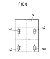
- the sealing element is executed in a variant of the invention as a sealing plate, which is essentially a same area (that is - apart from the height - same dimensions) and also a same hole pattern as the base plate has. It is possible that the opening cross section of the holes in the sealing plate from the opening cross section of the holes in the base plate deviates. However, this does not change the fundamentally identical hole pattern, which in particular results in an alignment of the holes in the sealing plate with holes in the base plate.
- the reinforcing element has a cross-sectionally C-shaped configuration.
- the open side of the C facing away from the traffic route, so pointing to the traffic route towards no sharp edges of the reinforcing element. A wheel of the vehicle touching the protective device is gently rejected, without getting caught in the reinforcing elements.
- the first post and the second post are arranged relative to each other such that the material-free region of the first post faces the second post.
- the material-free region of the second post also faces the first post. That is, a portion lying between the first and second posts is flanked on both sides by the material-free region of the first post and the material-free region of the second post.
- the first post is longer than the second post. That is, when a vehicle impacts on the guard and first bounces against the baffle, initially only the shorter second pillar is impacted with a corresponding impact energy.
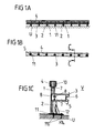
- the Figure 1A shows a side view of a section of a protective device with a plurality of first post 1 and a plurality of second posts 2, of which for clarity, only a few are provided with the corresponding reference numerals.
- a first post 1 and a second post 2 are arranged together on a common base plate 11 as a base plate by welding. This results in a plurality of pairs of posts, which are each mounted on a base plate 11. Furthermore, this results in an alternating sequence of first post 1 and second post 2.
- Each foot plate 11 is firmly anchored by means not shown anchors as fastening means in a substrate U.
- the spacers 5 serve not only the fixing and positioning of the guardrail 3, but in addition to receiving energy when a vehicle comes off the road and bounces against the guard.
- the aim is a relatively low effective range W (in particular W ⁇ 4), which with a protective device as in Figures 1A and 1B represented achieved.
- the first post 1 is arranged.
- a bracket 10 is connected as a connecting element fixed to the first post 1.
- the bracket 10 has a slot 7, which is penetrated by a screw and the bracket 10 thus fixed to the first post 1.
- the upper portion of the bracket 10 is disposed in the interior of the box section 4 and is encompassed by this.
- the bracket 10 is attached to the first post 1 in such a way that the box profile 4 connected to the bracket 10 is flush with the upper edge of the first post 1.
- first segment 40 When the first segment 40 is inserted with its connecting portion 41 in the second segment 42, it is positioned so that the openings 7 and 8 of the individual segments 40 and 42 are aligned with each other. In this way, 7 screws can then be introduced into the openings, which connect the first segment 40 with the second segment 42.
- a third opening 9 is additionally arranged, through which a screw or other fastening means for fastening the guard rail 3 to the spacer 5 can be guided.
Abstract
Description
Die Erfindung betrifft eine Schutzeinrichtung an Verkehrswegen gemäß dem Anspruch 1.The invention relates to a protective device on traffic routes according to
Aus der
Der vorliegenden Erfindung liegt die Aufgabe zugrunde, eine Schutzeinrichtung an Verkehrswegen bereitzustellen, die auf einer Vielzahl von unterschiedlich beschaffenen Untergründen, insbesondere auf einer Brücke, aufgestellt werden kann und dennoch ein gutes Aufhaltevermögen aufweist.The present invention has for its object to provide a protective device on roads, which can be placed on a variety of differently procured surfaces, especially on a bridge, and yet has a good retention.
Diese Aufgabe wird mit einer Schutzeinrichtung an Verkehrswegen mit den Merkmalen des Anspruchs 1 gelöst. Demnach weist eine derartige Schutzeinrichtung nicht nur einen einzigen Pfosten, an dem unterschiedliche Leit- oder Stabilisierungselemente befestigt sind, auf, sondern vielmehr mindestens einen ersten Pfosten, an dem mindestens ein Stabilisierungselement angebracht ist, und mindestens einen zweiten Pfosten, an dem mindestens ein Leitelement angebracht ist. Das Leitelement ist dabei mittels mindestens eines Distanzelementes mit dem zweiten Pfosten verbunden. Sowohl der erste Pfosten als auch der zweite Pfosten sind jeweils mit einem Untergrund, auf welchem die Schutzeinrichtung angeordnet ist, verbunden. Das Stabilisierungselement ist nicht mit dem oder den zweiten Pfosten verbunden, und das Leitelement ist nicht mit dem oder den ersten Pfosten verbunden.This object is achieved with a protective device on traffic routes with the features of
Bei dem Untergrund handelt es sich in einer Ausgestaltung der Erfindung um eine Brückenkonstruktion bzw. um einen Teil einer Brückenkonstruktion, nämlich insbesondere um eine Brückenkappe. Als Brückenkappe wird dabei der Bereich zwischen einem neben dem eigentlichen Verkehrsweg verlaufenden Bordstein und einer Außenkante der Brücke verstanden. Die Brückenkappe dient üblicherweise zur Aufnahme einer Schutzplanke und eines Geländers.In one embodiment of the invention, the substrate is a bridge construction or a part of a bridge construction, namely in particular a bridge cap. The bridge cap is understood to mean the area between a curb running alongside the actual traffic route and an outer edge of the bridge. The bridge cap usually serves to receive a protective barrier and a railing.
Mit einer erfindungsgemäßen Schutzeinrichtung wird der Effekt erzielt, dass die Pfosten mit dem Untergrund so verankert sind, dass zum einen keine Beton- oder Asphaltteile um die Verankerung herum aus dem Untergrund herausgerissen werden, wodurch eine Beschädigung des Untergrundes vermieden wird. Zum anderen bietet das Gesamtsystem der Schutzeinrichtung jedoch noch genügend Elastizität, um durch ein geeignetes Ausweichen der Gurte (das heißt, des Stabilisierungselementes und des Leitelementes) eine ausreichend hohe Aufnahme von Aufprallenergie zu gewährleisten.With a protective device according to the invention the effect is achieved that the posts are anchored to the ground so that on the one hand no concrete or asphalt parts are torn out of the ground around the anchorage, whereby damage to the substrate is avoided. On the other hand, however, the overall system of the guard still provides enough elasticity to ensure a sufficiently high absorption of impact energy by a suitable deflection of the straps (that is, the stabilizing element and the guide element).
In einer Ausgestaltung der Erfindung sind das Stabilisierungselement, das Leitelement und das Distanzelement sowie die Verbindung dieser Elemente untereinander in gleicher Weise ausgestaltet wie bei einer Schutzeinrichtung, die mittels gerammter Pfosten in einem Boden verankert ist. Das heißt, es können möglichst viele gleiche Konstruktionselemente wie bei einer gerammten Schutzeinrichtung verwendet werden, so dass der Aufbau einer Schutzeinrichtung, welche aus gerammten Teilabschnitten und auf andere Weise im Untergrund verankerten Teilabschnitten besteht, auf einfache Art und Weise ermöglicht wird.In one embodiment of the invention, the stabilizing element, the guide element and the spacer element and the connection of these elements are configured with each other in the same way as in a protective device which is anchored by means of rammed posts in a ground. That is, as many of the same structural elements as in a rammed guard can be used, so that the structure of a protective device, which consists of rammed sections and otherwise anchored underground sections, is made possible in a simple manner.
Insbesondere wenn die Schutzeinrichtung auf einer Brückenkappe aufgestellt werden soll, ergeben sich aufgrund der spezifischen örtlichen Ausgestaltungen von Brückenkonstruktionen besondere Anforderungen an die Schutzeinrichtung. So sind zur Deformation der Schutzeinrichtung zur Verfügung stehende Platzverhältnisse deutlich beschränkter als bei einer Anordnung auf einem anderen Untergrund. Das hat zur Folge, dass ein möglichst kleiner Wirkungsbereich (W ≤ 4) bei einer Aufhaltestufe H2 nach EN1317 erreicht werden sollte. Ferner ist bei einer Montage auf einer Brückenkappe zu berücksichtigen, dass Brückenkappen in der Regel eine genormte Ausgestaltung aufweisen, was eine zusätzliche Einschränkung der Variationsmöglichkeiten bedingt. Ferner ist aufgrund normativer Vorgaben regelmäßig ein Geländer auf einer Brückenkappe montiert. Dieses Geländer darf bei einer Deformation der Schutzeinrichtung nicht berührt werden, da die Schutzwirkung der Schutzeinrichtung ohne Zuhilfenahme des Geländers erzielt werden muss. Folglich ist der Raum, der zur dynamischen Verformung insbesondere der Gurte der Schutzeinrichtung zur Verfügung steht, äußerst beschränkt. Gleichzeitig muss dieser Raum jedoch voll ausgenutzt werden, um ein nichtverformungssteifes Schutzeinrichtungsgesamtsystem auszubilden. Wäre das Schutzeinrichtungsgesamtsystem verformungssteif, würde dies bei einem Aufprall eines Kraftfahrzeugs auf die Schutzeinrichtung dazu führen, dass große Teile der Brückenkonstruktion aus der Brückenkappe herausgerissen würden. Dadurch wäre die Stabilität der gesamten Brückenkonstruktion nicht mehr gewährleistet. Gleichzeitig kann jedoch keine Verstärkung der Brückenkappe zur Montage der Schutzeinrichtung erfolgen, da die Schutzeinrichtung dazu vorgesehen ist, auf bereits bestehenden Brücken montiert zu werden. Diese dürfen jedoch nicht nachträglich verstärkt werden.In particular, when the guard is to be placed on a bridge cap, arise due to the specific local configurations of bridge structures special requirements for the protective device. Thus, the space available for deformation of the protective device is much more limited than in an arrangement on another surface. This means that the smallest possible range of action (W ≤ 4) should be achieved for a containment stage H2 according to EN1317. Furthermore, when mounted on a bridge cap too take into account that bridge caps usually have a standardized design, which requires an additional restriction of the possible variations. Furthermore, due to normative specifications, a railing is regularly mounted on a bridge cap. This guardrail should not be touched during a deformation of the safety guard, as the protective effect of the safety guard must be achieved without the aid of the guardrail. Consequently, the space available for dynamic deformation, in particular the straps of the guard, is extremely limited. At the same time, however, this space must be fully exploited to form a non-deformable protector overall system. If the safety system as a whole would be rigid, this would mean that large parts of the bridge construction would be torn out of the bridge cap in the event of a motor vehicle colliding with the safety guard. As a result, the stability of the entire bridge construction would no longer be guaranteed. At the same time, however, no reinforcement of the bridge cap for mounting the protection device can take place, since the protective device is intended to be mounted on existing bridges. However, these must not be subsequently reinforced.
Die erfindungsgemäße Schutzeinrichtung erfüllt die Anforderungen zur Aufstellung auf einer Brückenkappe. So werden weder im oberen Bereich der Schutzeinrichtung zu große Verformungen zugelassen, noch wird die gesamte Aufpralllast bei einem Aufprallen eines Fahrzeugs auf die Schutzeinrichtung auf einzelne Pfosten bzw. einzelne Anker konzentriert.The protective device according to the invention meets the requirements for installation on a bridge cap. Thus, too much deformation is not allowed in the upper part of the guard, nor is the entire impact load is concentrated in a collision of a vehicle on the guard on individual posts or individual anchor.
In einer Variante der Erfindung ist das Stabilisierungselement als Leitelement ausgebildet, so dass die Schutzeinrichtung zwei an unterschiedlichen Pfosten befestigte Leitelemente aufweist.In a variant of the invention, the stabilizing element is designed as a guide element, so that the protective device has two guide elements fastened to different posts.
In einer weiteren Alternative der Erfindung ist das Stabilisierungselement als Kastenprofil ausgebildet. Das heißt, die Schutzeinrichtung weist dann ein an einem Pfosten befestigtes Kastenprofil und ein an einem anderen Pfosten befestigtes Leitelement auf.In a further alternative of the invention, the stabilizing element is designed as a box profile. That is, the guard then has a box profile attached to a post and a baffle attached to another post.
In einer Variante zeichnet sich die Schutzeinrichtung dadurch aus, dass zur Verbindung des Stabilisierungselements bzw. Kastenprofils mit dem ersten Pfosten mindestens ein Verbindungselement vorgesehen ist, das einerseits mit dem ersten Pfosten verbunden ist und das andererseits formschlüssig in dem Kastenprofil angeordnet ist. Dabei weist das als Kastenprofil ausgebildete Stabilisierungselement bevorzugt eine Öffnung auf, die an der Unterseite des Stabilisierungselements ausgebildet ist und in dessen Längsrichtung verläuft.In a variant, the protective device is characterized in that at least one connecting element is provided for connecting the stabilizing element or box profile with the first post, which is connected on the one hand to the first post and on the other hand is arranged in a form-fitting manner in the box section. In this case, the stabilizing element designed as a box profile preferably has an opening which is formed on the underside of the stabilizing element and extends in its longitudinal direction.
Durch diese Öffnung ist das Verbindungselement bei der Montage in das Kastenprofil einbringbar und bei der Demontage aus diesem entfernbar.Through this opening, the connecting element during assembly in the box section can be introduced and removed during disassembly of this.
Diese Befestigungsvariante kommt ohne Befestigungselemente wie Schrauben zwischen dem Verbindungselement und dem Stabilisierungselement aus, so dass größere Toleranzen hinsichtlich des Abstands der einzelnen ersten Pfosten zueinander möglich sind. Es spielt für diese Befestigung des Stabilisierungselements an den ersten Pfosten jeweils mittels eines Verbindungselements infolge des Verzichts auf Befestigungselemente keine wesentliche Rolle, ob der Abstand zwischen den einzelnen ersten Pfosten stets gleich ist. Somit ist die Montage der Schutzeinrichtung gegenüber anderen Schutzeinrichtungen vereinfacht.This mounting variant comes without fasteners such as screws between the connecting element and the stabilizing element, so that larger tolerances with respect to the distance of each first post to each other are possible. It plays for this attachment of the stabilizing element to the first post each by means of a connecting element due to the omission of fasteners no essential role, whether the distance between the individual first post is always the same. Thus, the installation of the protection device over other protection devices is simplified.
Bevorzugt erstreckt sich die Öffnung im Kastenprofil über die gesamte Länge des Stabilisierungselements. Dies erleichtert die Herstellung des Stabilisierungselements und reduziert den dazu benötigten Materialaufwand.Preferably, the opening in the box section extends over the entire length of the stabilizing element. This facilitates the production of the stabilizing element and reduces the required material cost.
Das Verbindungselement weist vorzugsweise eine im Wesentlichen plattenförmige Hauptfläche auf, die mit Aussparungen versehen sein kann und die im montierten Zustand im Wesentlichen senkrecht zur Längserstreckungsrichtung des Stabilisierungselements orientiert ist.The connecting element preferably has a substantially plate-shaped main surface, which may be provided with recesses and which is oriented in the mounted state substantially perpendicular to the longitudinal extension direction of the stabilizing element.
Damit das Verbindungselement durch die Öffnung in das Stabilisierungselement eingebracht werden kann, ist seine Hauptfläche zu Beginn der Montage des Stabilisierungselements am Verbindungselement vorzugsweise im Wesentlichen parallel zur Längserstreckungsrichtung des Hohlprofils angeordnet. Während der Montage wird das Verbindungselement im Hohlprofil gedreht, so dass seine Hauptfläche einen Winkel zwischen etwa 0° und etwa 90° zur Längserstreckungsrichtung des Hohlprofils aufweist. Dadurch wird das Verbindungselement in die Position verbracht, die es im montierten Zustand vorzugsweise einnimmt.So that the connecting element can be introduced through the opening in the stabilizing element, its main surface is preferably arranged at the beginning of assembly of the stabilizing element on the connecting element substantially parallel to the longitudinal direction of the hollow profile. During assembly, the connecting element is rotated in the hollow profile, so that its main surface has an angle between about 0 ° and about 90 ° to the longitudinal direction of the hollow profile. As a result, the connecting element is moved into the position which it preferably occupies in the mounted state.
Das Verbindungselement ist also derart ausgebildet, dass seine Hauptfläche während der Montage am Stabilisierungselement von einer Ausgangsposition, in der die Hauptfläche im Wesentlichen parallel zur Längserstreckungsrichtung des Hohlprofils verläuft und in die Öffnung des Hohlprofils einbringbar ist, in eine Endposition, in der die Hauptfläche im Wesentlichen senkrecht zur Längserstreckungsrichtung des Hohlprofils verläuft, verschwenkbar ist.The connecting element is thus designed such that its main surface during assembly on the stabilizing element from an initial position in which the main surface is substantially parallel to the longitudinal direction of the hollow profile and can be introduced into the opening of the hollow profile, in an end position in which the main surface substantially runs perpendicular to the longitudinal direction of the hollow profile, is pivotable.
Zur Erhöhung der Stabilität des Verbindungselements weist dieses vorzugsweise mindestens einen seitlichen Randbereich auf, der winklig an der Hauptfläche angeordnet ist. Dabei ist es vorteilhaft, wenn zwischen dem mindestens einen Randbereich und der Hauptfläche ein Winkel von 85° bis 95° ausgebildet ist, wobei insbesondere eine rechtwinklige Anordnung bevorzugt ist. Der mindestens eine Randbereich weist vorteilhafterweise eine Breite auf, die geringer ist als die Breite der Hauptfläche. Als Breite des Randbereichs wird dabei dessen kürzere Ausdehnung in einer Ebene verstanden, die der Randbereich in einem Winkel zur Hauptfläche ausbildet. Die Breite der Hauptfläche ist die Ausdehnung der Hauptfläche, die sich im montierten Zustand im Wesentlichen senkrecht zur Längserstreckungsrichtung des Stabilisierungselements bzw. Hohlprofils erstreckt.To increase the stability of the connecting element, this preferably has at least one lateral edge region, which is arranged at an angle to the main surface. It is advantageous if between the at least one edge region and the main surface an angle of 85 ° to 95 ° is formed, wherein in particular a right-angled arrangement is preferred. The at least one edge region advantageously has a width that is smaller than the width of the main surface. The width of the edge region is understood to mean its shorter extent in a plane which forms the edge region at an angle to the main surface. The width of the main surface is the extent of the main surface, which extends in the assembled state substantially perpendicular to the longitudinal direction of the stabilization element or hollow profile.
Vorzugsweise weist das Verbindungselement zwei abgewinkelte Randbereiche auf, so dass sich eine im Querschnitt Z-förmige Gestalt des Verbindungselements ergibt. Auf diese Weise wird eine hohe Stabilität des Verbindungselements erreicht. Die Randbereiche können unterschiedlich breit sein und auch in einem voneinander verschiedenen Winkel von der Hauptfläche des Verbindungselements abstehen.Preferably, the connecting element has two angled edge regions, so that results in a cross-sectionally Z-shaped shape of the connecting element. In this way, a high stability of the connecting element is achieved. The edge regions can be of different widths and also protrude at a different angle from the main surface of the connecting element.
Die formschlüssige Verbindung zwischen dem Verbindungselement und dem Hohlprofil wird vorzugsweise dadurch erreicht, dass das Hohlprofil das Verbindungselement insbesondere mit mindestens einem unteren Abschnitt umgreift, so dass es das Verbindungselement hinterschneidet. Der untere Abschnitt ist dabei vorzugsweise der zur Öffnung benachbart angeordnete Bereich des Hohlprofils. Eine hinterschneidende Verbindung zwischen beiden Elementen ist insbesondere dann gewährleistet, wenn so viele Schenkel oder Flächen des Hohlprofils um das Verbindungselement greifen, dass die beiden Elemente nicht mehr ohne Verdrillung oder Verdrehung voneinander gelöst werden können.The positive connection between the connecting element and the hollow profile is preferably achieved in that the hollow profile surrounds the connecting element, in particular with at least one lower portion, so that it undercuts the connecting element. The lower section is preferably the region of the hollow profile arranged adjacent to the opening. An undercut connection between the two elements is ensured, in particular, when so many legs or surfaces of the hollow profile engage around the connecting element that the two elements can no longer be detached from each other without twisting or twisting.
Neben der formschlüssigen Verbindung wird bevorzugt zusätzlich eine kraftschlüssige Verbindung zwischen dem Hohlprofil und dem Verbindungselement dadurch bereitgestellt, dass das Verbindungselement mit seinem mindestens einen seitlichen Randbereich zumindest abschnittsweise gegen mindestens eine innere Seitenfläche des Hohlprofils drückt und dadurch eine Klemmung zwischen dem Hohlprofil und dem Verbindungselement aufbaut.In addition to the positive connection, a frictional connection between the hollow profile and the connecting element is preferably additionally provided in that the connecting element with its at least one lateral edge region at least partially presses against at least one inner side surface of the hollow profile and thereby builds a clamping between the hollow profile and the connecting element.
Die Verbindung zwischen dem Hohlprofil und dem Verbindungselement ist vorzugsweise so ausgestaltet, dass sie durch eine Kraft, die auf die Schutzeinrichtung infolge eines Aufpralls eines Fahrzeugs einwirkt, wieder lösbar ist. Das heißt, dass sich das Stabilisierungselement bei einer ausreichend hohen Krafteinwirkung auf die Schutzeinrichtung aus dem Verbindungselement ausdreht und bereits dabei sowie durch eine anschließende Verformung Energie aus dem Aufprall des Fahrzeugs absorbieren kann.The connection between the hollow profile and the connecting element is preferably designed such that it can be released again by a force which acts on the protective device as a result of an impact of a vehicle. This means that the stabilizing element at a sufficiently high force on the protective device from the Unscrewing the connection element and can absorb energy from the impact of the vehicle already here and by a subsequent deformation.
Um eine Befestigung des Verbindungselements am Pfosten zu erreichen, weist das Verbindungselement vorzugsweise einen länglichen Durchbruch, insbesondere ein Langloch auf, der in einem unteren Abschnitt des Verbindungselements angeordnet ist. Dieser untere Abschnitt des Verbindungselements ist dabei nicht innerhalb des Stabilisierungselements angeordnet. Um eine sichere Fixierung des Verbindungselements an dem Pfosten zu erreichen, ist es vorzugsweise durch mindestens ein Befestigungsmittel an dem Pfosten fixiert. Als solches Befestigungsmittel kommt insbesondere eine Schraube oder eine Niete in Betracht.In order to achieve an attachment of the connecting element to the post, the connecting element preferably has an elongated opening, in particular a slot, which is arranged in a lower portion of the connecting element. This lower portion of the connecting element is not arranged inside the stabilizing element. In order to achieve a secure fixation of the connecting element to the post, it is preferably fixed by at least one fastening means to the post. In particular, a screw or a rivet is considered as such a fastening means.
Das Distanzelement weist vorzugsweise einen Befestigungsbereich mit Durchbrüchen auf, in dem es durch mindestens ein Befestigungselement mit dem Pfosten verbunden ist, wobei das Befestigungselement dazu durch einen der in den Befestigungsbereich des Distanzelements angeordneten Durchbrüche greift. Ferner ist die Anzahl der Durchbrüche im Befestigungsbereich des Distanzelements bevorzugt größer als die Anzahl der Befestigungselemente, die durch die Durchbrüche hindurch greifen.The spacer element preferably has a fastening region with openings, in which it is connected by at least one fastening element with the post, wherein the fastening element engages thereto through one of the arranged in the fastening region of the spacer element openings. Furthermore, the number of openings in the attachment region of the spacer element is preferably greater than the number of attachment elements which reach through the openings.
In einer bevorzugten Ausgestaltung der Erfindung ist die Gesamthöhe der Schutzeinrichtung, gemessen von der Oberkante des Bodens, auf dem die Schutzeinrichtung angeordnet ist, bis zur Oberkante des Stabilisierungselements oder bis zur Oberkante des ersten Pfostens oder bis zur Oberkante des zweiten Pfostens (insbesondere je nachdem, welche dieser Oberkanten am weitesten vom Untergrund entfernt ist), größer als 80 cm, insbesondere größer als 85 cm, und kleiner oder gleich 90 cm.In a preferred embodiment of the invention, the total height of the protective device, measured from the top of the floor on which the protective device is arranged, to the top of the stabilizing element or to the top of the first post or to the top of the second post (in particular, depending on which of these upper edges is farthest from the ground), greater than 80 cm, in particular greater than 85 cm, and less than or equal to 90 cm.
Durch den Verzicht auf eine Anzahl von Befestigungselementen bei gleichzeitigem Vorhandensein von Durchbrüchen und einer damit verbundenen Materialersparnis in dem Distanzelement und in dem Pfosten wird der Materialaufwand der Schutzeinrichtung signifikant reduziert. Auch lässt sich durch eine besonders kompakte Bauweise, die sich in einer niedrigen Gesamthöhe der Schutzeinrichtung ausdrückt, eine erhebliche Materialreduktion erreichen. So können vorteilhafterweise Standardelemente, aus denen auch bekannte Schutzeinrichtungen aufgebaut sind, durch eine entsprechende neue, eine geringere Gesamthöhe der Schutzeinrichtung ermöglichende Kombination - ggf. unter Verzicht auf eine Anzahl von Befestigungselementen - zur Montage einer erfindungsgemäßen Schutzeinrichtung verwendet werden. Aus der Anordnung der einzelnen Elemente der Schutzeinrichtung ergibt sich trotz der dabei erfindungsgemäß erreichten Materialreduktion eine Stabilität, die den hohen, gewünschten Anforderungen entspricht.By dispensing with a number of fasteners in the simultaneous presence of breakthroughs and an associated saving of material in the spacer element and in the post material costs of the protection device is significantly reduced. Also can be achieved by a particularly compact design, which expresses itself in a low overall height of the protective device, a significant reduction in material. Thus, advantageously, standard elements from which known protective devices are constructed, by a corresponding new, a lower overall height of the protective device enabling combination - possibly waiving a number of fasteners - are used for mounting a protective device according to the invention. From the arrangement of the individual Elements of the protective device results in spite of the inventively achieved material reduction stability that meets the high, desired requirements.
Um einen Stabilisierungseffekt des Stabilisierungselements für die Schutzeinrichtung zu verstärken, ist das Stabilisierungselement vorzugsweise derart an einem oberen Bereich des ersten Pfostens angeordnet, dass es die Oberkante des Pfostens überdeckt und so den oberen Abschluss der Schutzeinrichtung darstellt.In order to enhance a stabilizing effect of the stabilizing element for the protective device, the stabilizing element is preferably arranged on an upper region of the first post such that it covers the upper edge of the post and thus represents the upper end of the protective device.
Vorzugsweise bestehen das Stabilisierungselement und/oder das Leitelement aus mindestens zwei Segmenten, wobei jedes dieser Segmente an seinem ersten Ende einen ersten Verbindungsteilbereich und an seinem zweiten Ende einen zweiten Verbindungsteilbereich aufweist. Als Enden der Segmente sollen dabei die Endbereiche der Segmente verstanden werden, die in Längserstreckungsrichtung der Segmente am weitesten vom jeweiligen Mittelpunkt der Segmente entfernt angeordnet sind. Der erste Verbindungsteilbereich eines ersten Segments kann dabei mit dem zweiten Verbindungsteilbereich eines zweiten Segments derart in Verbindung gebracht werden, dass ein Verbindungsbereich entsteht, über den beide Segmente miteinander verbunden sind.Preferably, the stabilizing element and / or the guide element consist of at least two segments, each of these segments having at its first end a first connecting portion and at its second end a second connecting portion. The ends of the segments are to be understood as the end regions of the segments, which are arranged in the longitudinal extension direction of the segments farthest from the respective center of the segments. The first connection portion of a first segment can be associated with the second connection portion of a second segment in such a way that a connection area is formed, via which both segments are interconnected.
Um eine schnelle und einfache Verbindung zweier Segmente zu ermöglichen, weist jedes Segment vorzugsweise an seinem ersten Verbindungsteilbereich einen geringeren Querschnitt auf als an seinem zweiten Verbindungsteilbereich. Dieser Querschnitt kann sich einerseits auf das gesamte Segment beziehen, andererseits aber auch nur die Profilbreiten des Segmentes umfassen. Mit dieser unterschiedlichen Querschnittsausprägung in den beiden Verbindungsteilbereichen eines jeden Segments ist es möglich, zwei Segmente ineinander zu stecken. Dazu wird der erste Verbindungsteilbereich eines ersten Segments in den zweiten Verbindungsteilbereich eines zweiten Segments eingeführt. Je nach Größe und Art der Querschnittsdifferenz zwischen den Verbindungsteilbereichen, insbesondere je nach Übergang des Verbindungsteilbereichs mit dem geringeren Querschnitt zum durchschnittlichen Querschnitt des Segments, sind unterschiedlich große Abschnitte eines jeden Segments Teil des Verbindungsbereichs.In order to enable a quick and easy connection of two segments, each segment preferably has a smaller cross-section at its first connection portion than at its second connection portion. On the one hand, this cross-section may relate to the entire segment, but on the other hand, it may include only the profile widths of the segment. With this different cross-sectional shape in the two connecting portions of each segment, it is possible to insert two segments into each other. For this purpose, the first connection portion of a first segment is introduced into the second connection portion of a second segment. Depending on the size and type of cross-sectional difference between the connecting portions, in particular depending on the transition of the connecting portion with the smaller cross-section to the average cross section of the segment, different sized sections of each segment are part of the connecting portion.
Um eine Verbindung zwischen zwei Segmenten nicht nur durch ein Ineinanderstecken oder ein Aufeinanderlegen der Verbindungsteilbereiche zu erreichen, weisen die Verbindungsteilbereiche vorzugsweise Durchbrüche auf, die bei der Bildung eines gemeinsamen Verbindungsbereichs von zwei Verbindungsteilbereichen miteinander fluchten und mit Befestigungsmitteln versehen werden können.In order to achieve a connection between two segments not only by a nesting or a juxtaposition of the connecting portions, the connecting portions preferably have openings, which are aligned with each other in the formation of a common connection region of two connecting portions and can be provided with fastening means.
Vorzugsweise ist die Erfindung so ausgestaltet, dass zumindest ein Befestigungselement zum Fixieren zweier Segmente durch einen der erwähnten Durchbrüche hindurch greift. Wird als Befestigungselement eine Schraube verwendet, lassen sich zwei Segmente auf diese Weise fest miteinander verschrauben. Die Anzahl der Durchbrüche im Verbindungsbereich zweier Segmente ist dabei größer als die Anzahl der Befestigungselemente, die durch die Durchbrüche hindurch greifen. Auf diese Art und Weise, die mit der Materialersparnis, die durch eine Reduktion der Befestigungselemente zur Befestigung des Distanzelements an dem Pfosten erreicht wird, vergleichbar ist, wird eine zusätzliche Materialreduktion der Schutzeinrichtung erreicht. Bei der Reduktion der Anzahl der Befestigungselemente muss jedoch darauf geachtet werden, dass die Stabilität der Schutzeinrichtung, die auch durch die Verbindung zwischen den Segmenten des Stabilisierungselements und/oder des Leitelements beeinflusst wird, nicht unerwünscht erniedrigt wird.Preferably, the invention is configured such that at least one fastening element for fixing two segments engages through one of the openings mentioned. If a screw is used as the fastening element, two segments can be screwed together in this way. The number of openings in the connecting region of two segments is greater than the number of fasteners that reach through the openings. In this way, which is comparable to the material savings achieved by reducing the fasteners for attachment of the spacer to the post, additional material reduction of the guard is achieved. In reducing the number of fasteners, however, care must be taken that the stability of the protective device, which is also influenced by the connection between the segments of the stabilizing element and / or the guide element, is not undesirably lowered.
Um die Montage des Distanzelements an dem zweiten Pfosten zu erleichtern, weist das Distanzelement vorzugsweise mindestens ein Verbindungsmittel auf, das zur Verbindung des Distanzelements mit dem zweiten Pfosten dient. Dazu greift das Verbindungselement in ein Aufnahmemittel am zweiten Pfosten ein. Das Distanzelement kann anschließend, während es bereits durch die Verbindung zwischen dem Verbindungsmittel und dem Aufnahmemittel gehalten wird, durch mindestens ein Befestigungselement am zweiten Pfosten fixiert werden. Das Verbindungsmittel kann beispielsweise in Form eines Hakens an das Distanzelement angeformt sein, wobei dieser Haken dann in eine entsprechende Lasche als Aufnahmemittel eingeführt werden kann. So ergibt sich eine Steckverbindung zwischen dem Distanzelement und dem zweiten Pfosten.In order to facilitate the mounting of the spacer element on the second post, the spacer element preferably has at least one connecting means which serves to connect the spacer element to the second post. For this purpose, the connecting element engages in a receiving means on the second post. The spacer element can then, while it is already held by the connection between the connecting means and the receiving means, be fixed by at least one fastening element on the second post. The connecting means may be formed, for example in the form of a hook on the spacer element, said hook can then be inserted into a corresponding tab as receiving means. This results in a plug connection between the spacer element and the second post.
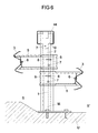
Das Distanzelement ist vorzugsweise derart am zweiten Pfosten angeordnet, dass es sich im Wesentlichen nur in eine Richtung vom zweiten Pfosten aus erstreckt. In einer alternativen Ausgestaltung der Erfindung ist das Distanzelement derart an dem zweiten Pfosten angeordnet, dass es sich im Wesentlichen zu gleichen Teilen zu beiden Seiten des zweiten Pfostens erstreckt. Die beiden Seiten des Pfostens umfassen dabei eine Vorder- und Rückseite des Pfostens, wobei die Vorderseite der Rückseite gegenüber angeordnet ist. Schaut man im seitlichen Querschnitt auf eine Schutzeinrichtung mit derartig angeordnetem Distanzelement und Pfosten, so ergibt sich eine kreuzförmige Anordnung zwischen Distanzelement und Pfosten.The spacer element is preferably arranged on the second post such that it extends substantially only in one direction from the second post. In an alternative embodiment of the invention, the spacer element is arranged on the second post such that it extends in substantially equal parts to both sides of the second post. The two sides of the post thereby comprise a front and a back of the post, with the front side facing the back. If one looks in the lateral cross-section of a protective device with such arranged spacer element and posts, the result is a cross-shaped arrangement between the spacer element and posts.
Damit die Schutzeinrichtung nicht nur einen Verkehrsweg, sondern zwei Verkehrswege bzw. zwei Richtungsfahrbahnen eines Verkehrswegs gleichzeitig schützen kann, weist das Distanzelement vorzugsweise zwei Leitelemente auf, von denen eines auf der Vorderseite und das andere auf der Rückseite des Pfostens angeordnet ist. Dies kann insbesondere dann sinnvoll sein, wenn auf der dem zu schützenden Verkehrsweg abgewandten Seite der Schutzeinrichtung ein weiterer zu schützender Verkehrsweg (beispielsweise ein Fahrradweg) liegt. Durch diese Bauweise kann auch - insbesondere bei schmalen Mittelstreifen - eine kompakte Schutzeinrichtung für zwei angrenzende Verkehrswege bzw. Richtungsfahrbahnen eines Verkehrswegs bereitgestellt werden. Diese Bauweise eignet sich insbesondere dann, wenn kein Niveauunterschied zwischen den beiden Verkehrswegen besteht.So that the protection device can protect not only one traffic route, but two traffic routes or two directional traffic lanes of a traffic route at the same time, the spacer element preferably has two guide elements, one of which on the front side and the other is arranged on the back of the post. This may be useful, in particular, if there is another traffic route to be protected (for example, a cycle path) on the side of the protection device facing away from the traffic route to be protected. This design can also - especially for narrow median strip - a compact protection device for two adjacent traffic routes or directional lanes of a traffic route are provided. This construction is particularly suitable if there is no difference in level between the two traffic routes.
Eine vergleichbare Ausgestaltung der Schutzeinrichtung lässt sich alternativ auch dadurch erreichen, dass nicht ein gemeinsames Distanzelement, sondern zwei getrennte Distanzelemente verwendet werden. Jedes einzelne dieser beiden Distanzelemente würde bei dieser Ausgestaltung mit einem Leitelement versehen sein, wobei das eine Leitelement zur Vorderseite und das andere Leitelement zur Rückseite des Pfostens gerichtet wäre.A comparable embodiment of the protective device can alternatively also be achieved by not using a common spacer element but two separate spacer elements. Each of these two spacer elements would be provided in this embodiment with a guide element, wherein the one guide element to the front and the other guide element would be directed to the back of the post.
Um zwei Verkehrswege bzw. zwei Richtungsfahrbahnen eines Verkehrswegs, die über einen schmalen Mittelstreifen miteinander verbunden sind und die darüber hinaus einen Niveauunterschied aufweisen, auch mit einer erfindungsgemäßen Schutzeinrichtung versehen zu können, sind das erste und das zweite Distanzelement in einer bevorzugten Ausgestaltung der Erfindung nicht in der gleichen, sonder in unterschiedlicher Höhe an dem Pfosten angebracht. Dadurch befinden sich auch die an den Distanzelementen angeordneten Leitelemente in unterschiedlicher Höhe gegenüber dem Untergrund an der Position des Pfostens. Dadurch lässt sich in die gewünschte Höhe der Leitelemente gegenüber dem Niveau der Oberfläche des jeweiligen Verkehrswegs wunschgemäß einstellen.In order to provide two traffic routes or two directional lanes of a traffic route, which are connected to each other over a narrow central strip and also have a difference in level, to be provided with a protective device according to the invention, the first and the second spacer element are not in a preferred embodiment of the invention the same, but at different heights attached to the post. As a result, the guide elements arranged on the spacer elements are at different heights relative to the ground at the position of the post. This makes it possible to set in the desired height of the guide elements with respect to the level of the surface of the respective traffic route as desired.
Damit die erfindungsgemäße Schutzeinrichtung trotz ihrer kompakten Bauweise bzw. der Materialreduktion eine hohe Stabilität aufweist, sind die Elemente der Schutzeinrichtung, insbesondere die Pfosten und die Distanzelemente, so zueinander angeordnet, dass die Schutzeinrichtung ein Aufhaltvermögen aufweist, welches zumindest der Aufhaltestufe H2, ermittelt nach EN 1317-2, aufweist. Prinzipiell ist die Schutzeinrichtung aber auch so gestaltbar, dass sie eine andere Aufhaltestufe erreichen kann.In order for the protective device according to the invention, despite its compact design and material reduction, to have a high stability, the elements of the protective device, in particular the posts and the spacer elements, are arranged relative to each other such that the protective device has a holding capacity which at least the containment level H2, determined according to EN 1317-2. In principle, however, the protective device can also be designed so that it can reach a different degree of containment.
In einer alternativen Ausgestaltung sind der erste Pfosten und/oder der zweite Pfosten mit dem jeweiligen Ende in Längserstreckungsrichtung der Pfosten, welches in montiertem Zustand zum Untergrund hinweist, mit einer Grundplatte verbunden. Dabei ist es möglich, dass jeder Pfosten auf einer separaten Grundplatte angeordnet ist. Die Verbindung des ersten Pfostens und/oder des zweiten Pfostens mit der Grundplatte kann insbesondere durch ein Verschweißen erfolgen, wobei auch Vernietungen, Verschraubungen und ähnliche Verbindungen denkbar sind.In an alternative embodiment, the first post and / or the second post with the respective end in the longitudinal direction of the post, which points in the mounted state to the ground, connected to a base plate. It is possible that each post is arranged on a separate base plate. The connection of the first post and / or the second post with the base plate can in particular be done by welding, with rivets, fittings and similar compounds are conceivable.
Um eine einfache Verbindung zwischen der Schutzeinrichtung und dem Untergrund zu ermöglichen, ist die Grundplatte dafür vorgesehen und eingerichtet, mit dem Untergrund verbunden zu werden. Dazu weist die Grundplatte mehrere Durchbrüche auf, welche zur Aufnahme von Bolzen, Schrauben oder Ankern geeignet sind. Diese Befestigungselemente können wahlweise unter Verwendung geeigneter Unterlegscheiben in die entsprechenden Durchbrüche eingeführt werden.In order to allow a simple connection between the protection device and the ground, the base plate is provided and adapted to be connected to the ground. For this purpose, the base plate on several openings, which are suitable for receiving bolts, screws or anchors. These fasteners may optionally be inserted using suitable washers in the respective openings.
Um Unebenheiten im Untergrund auszugleichen oder zu verhindern, dass zwischen der Oberfläche des Untergrundes und der Unterseite der Grundplatte Flüssigkeiten oder andere Stoffe unter die Grundplatte eindringen können, ist in einer alternativen Ausgestaltung ein Dichtelement in montiertem Zustand der Schutzeinrichtung zwischen der Grundplatte und dem Untergrund angeordnet.In order to compensate for unevenness in the substrate or to prevent liquids or other substances from penetrating under the base plate between the surface of the substrate and the underside of the base plate, in an alternative embodiment a sealing element is arranged between the base plate and the substrate in the assembled state of the protective device.
Um eine besonders einfache und unauffällige Anordnung des Dichtungselements unterhalb der Grundplatte zu erreichen, ist das Dichtungselement in einer Variante der Erfindung als Dichtungsplatte ausgeführt, die im Wesentlichen eine gleiche Fläche (das heißt - abgesehen von der Höhe - gleiche Dimensionen) und auch ein gleiches Lochbild wie die Grundplatte aufweist. Dabei ist es möglich, dass der Öffnungsquerschnitt der Löcher in der Dichtungsplatte vom Öffnungsquerschnitt der Löcher in der Grundplatte abweicht. Dies ändert jedoch nichts am grundsätzlich gleichen Lochbild, das insbesondere ein Fluchten der Löcher in der Dichtungsplatte mit Löchern in der Grundplatte zur Folge hat.In order to achieve a particularly simple and inconspicuous arrangement of the sealing element below the base plate, the sealing element is executed in a variant of the invention as a sealing plate, which is essentially a same area (that is - apart from the height - same dimensions) and also a same hole pattern as the base plate has. It is possible that the opening cross section of the holes in the sealing plate from the opening cross section of the holes in the base plate deviates. However, this does not change the fundamentally identical hole pattern, which in particular results in an alignment of the holes in the sealing plate with holes in the base plate.
Um eine besonders einfache Montage und eine gute Stabilität der Schutzeinrichtung zu gewährleisten, sind der erste Pfosten und der zweite Pfosten in einer Variante der Erfindung mit einer gemeinsamen Grundplatte verbunden. Dadurch ist es auf besonders vorteilhafte Weise möglich, eine Grundplatte mit einem Standardlochbild zu verwenden, welches eine einfache Verbindung dieser Grundplatte mit standardmäßig in einer Brückenkappe vorgesehenen Aufnahmeöffnungen für Befestigungselemente ermöglicht. Das hat zur Folge, dass umfangreiche bauliche Maßnahmen für das Setzen neuer Anker bzw. Befestigungsmittel nicht erforderlich sind. Da zudem die auf die Befestigungsmittel wirkenden Kräfte (Ankerkräfte) und die Beanspruchung der Grundplatte sehr stark von dem Abstand der einzelnen Befestigungselemente zueinander abhängt, dürfen die Befestigungselemente nicht zu weit voneinander entfernt angeordnet sein. Dies trifft insbesondere deswegen zu, da die Anker- bzw. Befestigungselemente hinsichtlich der maximal aufnehmbaren Zugkräfte regelmäßig nur eine beschränkte Zulassung aufweisen. Folglich ist es vorteilhaft, wenn die Abstände zwischen den Befestigungselementen im Normbereich liegen, so dass standardmäßig zugelassene Befestigungselemente bzw. Anker eingesetzt werden können.In order to ensure a particularly simple assembly and good stability of the protective device, the first post and the second post are connected in a variant of the invention with a common base plate. This makes it possible in a particularly advantageous manner to use a base plate with a standard hole pattern, which allows easy connection of this base plate with standard provided in a bridge cap receiving openings for fasteners. As a result, extensive structural measures for setting new anchor or fasteners are not required. In addition, since the forces acting on the fastening means (anchor forces) and the stress of the base plate very much on the distance of the individual fasteners depends on each other, the fasteners may not be too far apart. This is especially true because the anchor or fasteners in terms of maximum absorbable tensile forces regularly have only a limited approval. Consequently, it is advantageous if the distances between the fastening elements are in the normal range, so that standard approved fasteners or anchors can be used.
In einer alternativen Ausgestaltung sind die Pfosten zueinander versetzt auf der Grundplatte angeordnet. Dabei ist es insbesondere vorgesehen, dass der zweite Pfosten näher an einem Verkehrsweg angeordnet ist als der erste Pfosten. Das hat zur Folge, dass auch das Leitelement näher am Verkehrsweg angeordnet ist als das Stabilisierungselement. Durch das eingesetzte Distanzelement ist das Leitelement zwar unabhängig von der relativen Pfostenanordnung näher am Verkehrsweg, doch wird durch die Pfostenanordnung eine weitere Verschiebung zum Verkehrweg erzielt. Prallt nun ein Fahrzeug auf die Schutzeinrichtung, so trifft es zuerst auf das Leitelement, so dass anfänglich auftretende Aufprallkräfte über das Leitelement in den zweiten Pfosten eingeleitet werden. Dieser Pfosten kann dabei bis zu seiner Bruchlast beansprucht werden. Ein Teil der anfallenden Aufprallenergie wird dabei in den Untergrund abgeleitet. Im weiteren zeitlichen Verlauf des Aufpralls des Fahrzeugs auf die Schutzeinrichtung wird durch Verformung des Stabilisierungselements auch der erste Pfosten mit einer entsprechenden Aufprallenergie beaufschlagt, so dass es zu einer Deformation des ersten Pfostens kommt. Das heißt, die gesamte Aufprallenergie wird in zwei zeitlich voneinander getrennten Stufen über den zweiten Pfosten und den ersten Pfosten sowie einer gegebenenfalls vorhandenen Grundplatte in den Untergrund eingeleitet. Durch diese Aufteilung der auf die Schutzeinrichtung wirkenden Last wird eine günstigere Energieeinleitung in den Untergrund erreicht. Das hat zur Folge, dass die Befestigungsmittel, die zur Befestigung der Grundplatte auf dem Untergrund verwendet werden, weniger stark auf einmal beansprucht werden als dies bei herkömmlichen Systemen der Fall ist. Gleichfalls wird der Untergrund wesentlich günstiger mit Energie bzw. Kraft beaufschlagt, so dass das Herauslösen einzelner Teile aus dem Untergrund bei einem Aufprall auf die Schutzeinrichtung vermieden wird.In an alternative embodiment, the posts are arranged offset to one another on the base plate. It is provided in particular that the second post is arranged closer to a traffic route than the first post. This has the consequence that the guide element is arranged closer to the traffic route than the stabilizing element. Although the guide element is independent of the relative post arrangement closer to the traffic route due to the spacer element used, a further shift to the traffic route is achieved by the post arrangement. If a vehicle collides with the protective device, it first strikes the guide element, so that initially occurring impact forces are introduced via the guide element into the second post. This post can be claimed up to its breaking load. Part of the resulting impact energy is dissipated in the underground. In the further time course of the impact of the vehicle on the protective device, the first post is subjected to a corresponding impact energy by deformation of the stabilizing element, so that a deformation of the first post occurs. That is, the entire impact energy is introduced in two temporally separate stages on the second post and the first post and an optional base plate in the underground. By this division of the load acting on the protective device a more favorable energy input into the ground is achieved. This has the consequence that the fasteners that are used to attach the base plate on the ground, less stressed at one time than is the case with conventional systems. Likewise, the substrate is much cheaper charged with energy or force, so that the detachment of individual parts from the ground is avoided in an impact on the protective device.
Durch ein gegeneinander versetztes Anordnen der Pfosten auf der Grundplatte wird zudem ein größerer Freiheitsgrad in der Deformation des einzelnen Pfostens ermöglicht. Dadurch wird auch eine möglichst späte Anlehnung des verformten Gurtes (das heißt, des verformten Leitelements bzw. des verformten Stabilisierungselements) am jeweils anderen Pfosten erreicht. Damit wird die Wahrscheinlichkeit, dass der zuerst belastete zweite Pfosten bis zu seiner Bruchlast mit Kraft beaufschlagt wird, erhöht, so dass der zweite Pfosten bricht, bevor das Leitelement an den bis dahin unverformten ersten Pfosten aufprallen kann.By a staggered arrangement of the posts on the base plate also allows a greater degree of freedom in the deformation of the individual post. As a result, as late as possible a matching of the deformed belt (that is, the deformed guide element or the deformed stabilizing element) is achieved at the other post. Thus, the probability that the first loaded second post is acted up to its breaking load, increased, so that the second post breaks before the guide element can bounce on the hitherto undeformed first post.
Um eine bessere Krafteinleitung von dem ersten Pfosten und/oder dem zweiten Pfosten in den Untergrund bzw. die Grundplatte zu ermöglichen, ist mindestens ein Verstärkungselement an dem ersten Pfosten und/oder an dem zweiten Pfosten angebracht. Dieses Verstärkungselement bewirkt eine erhöhte Stabilität des jeweiligen Pfostens gegenüber einer auf den jeweiligen Pfosten einwirkenden Kraft. Dadurch wird bei einer Biegebeanspruchung des mit Kraft beaufschlagten Pfostens eine höhere Bruchlast des Pfostens erreicht. Die Bruchlast wird in der Regel an der Verbindungsstelle zwischen dem Pfosten und der Grundplatte zuerst erreicht. Durch das Verstärkungselement kann eine Beanspruchung der Verbindungsstelle zwischen dem Pfosten und der Grundplatte jedoch verringert werden.In order to allow a better introduction of force from the first post and / or the second post into the ground or the base plate, at least one reinforcing element is attached to the first post and / or to the second post. This reinforcing element causes increased stability of the respective post relative to a force acting on the respective post. As a result, a higher breaking load of the post is achieved with a bending load of the loaded post. The breaking load is usually reached at the junction between the post and the base plate first. By the reinforcing element, however, stress on the joint between the post and the base plate can be reduced.
Um eine besonders einfache Verbindung des Verstärkungselementes mit der Grundplatte zu ermöglichen, ist dieses mit der Grundplatte verschweißt; andere Verbindungsverfahren können aber grundsätzlich auch angewandt werden. Dabei ist insbesondere vorgesehen, eine Schweißnaht zwischen dem Verstärkungselement und der Grundplatte in diskontinuierlicher Weise auszuführen, so dass Lücken bzw. Hohlräume zwischen dem Verstärkungselement und der Grundplatte auftreten. Aufgrund dieser Hohlräume ist es grundsätzlich möglich, eine innere Schweißnaht anzubringen. Ferner ist es möglich, dass Wasser oder andere Flüssigkeiten, die sich im Bereich der Verstärkungselemente ansammeln, von der einen Seite des Verstärkungselements auf die andere Seite des Verstärkungselements zu bringen. Dies ist besonders dann von Interesse, wenn die Grundplatte nicht absolut flach, sondern leicht geneigt angeordnet wird, so dass ein Strömen einer Flüssigkeit entlang der Grundplatte erzwungen wird. Auf diese Weise ist es möglich, beispielsweise Wasser, welches von einem oberen Bereich der Schutzeinrichtung an einzelnen Elementen der Schutzeinrichtung hinunterläuft, gezielt von der Schutzeinrichtung weg zu führen.In order to allow a particularly simple connection of the reinforcing element to the base plate, this is welded to the base plate; However, other connection methods can also be used in principle. In particular, it is provided to perform a weld between the reinforcing element and the base plate in a discontinuous manner, so that gaps or cavities between the reinforcing element and the base plate occur. Because of these cavities, it is basically possible to attach an inner weld. Furthermore, it is possible for water or other liquids, which accumulate in the region of the reinforcing elements, to be brought from one side of the reinforcing element to the other side of the reinforcing element. This is of particular interest when the base plate is not placed absolutely flat, but slightly inclined so that a flow of liquid along the base plate is forced. In this way, it is possible, for example, water, which runs down from an upper portion of the protection device to individual elements of the protection device, specifically to lead away from the protection device.
In einer Variante der Erfindung weist das Verstärkungselement eine im Querschnitt C-förmige Ausgestaltung auf. Dabei ist die offene Seite des C (ein materialfreier Bereich des C-förmigen Profils) vom Verkehrsweg abgewandt, so dass zum Verkehrsweg hin keine scharfen Kanten des Verstärkungselements hinweisen. Ein Rad eines die Schutzeinrichtung berührenden Fahrzeugs wird dabei schonend abgewiesen, ohne sich in den Verstärkungselementen zu verhaken.In a variant of the invention, the reinforcing element has a cross-sectionally C-shaped configuration. Here, the open side of the C (a material-free area of the C-shaped profile) facing away from the traffic route, so pointing to the traffic route towards no sharp edges of the reinforcing element. A wheel of the vehicle touching the protective device is gently rejected, without getting caught in the reinforcing elements.
Um besonders günstige Deformationseigenschaften zu ermöglichen, sind der erste Pfosten und/oder der zweite Pfosten in einer Variante in einer im Querschnitt C-förmigen Ausgestaltung ausgebildet. Dadurch kann eine Verwindung der Pfosten beim Biegen erreicht werden, so dass bei einer Maximalbeanspruchung noch eine Verformbarkeit des jeweiligen Pfostens oberhalb seiner Versteifung erreicht wird. Zwischen den beiden Enden des C liegt bei einer derartigen Ausgestaltung ein materialfreier Bereich vor.In order to allow particularly favorable deformation properties, the first post and / or the second post are formed in a variant in a cross-sectionally C-shaped configuration. As a result, a twisting of the posts when bending is achieved be so that at a maximum stress nor a deformability of the respective post above its stiffening is achieved. Between the two ends of the C, a material-free region is present in such an embodiment.
In einer Variante der Erfindung sind der erste Pfosten und der zweite Pfosten derart zueinander angeordnet, dass der materialfreie Bereich des ersten Pfostens dem zweiten Pfosten zugewandt ist. Insbesondere ist auch der materialfreie Bereich des zweiten Pfostens dem ersten Pfosten zugewandt. Das heißt, ein zwischen dem ersten und dem zweiten Pfosten liegender Abschnitt ist auf seinen beiden Seiten von dem materialfreien Bereich des ersten Pfostens und dem materialfreien Bereich des zweiten Pfostens flankiert.In a variant of the invention, the first post and the second post are arranged relative to each other such that the material-free region of the first post faces the second post. In particular, the material-free region of the second post also faces the first post. That is, a portion lying between the first and second posts is flanked on both sides by the material-free region of the first post and the material-free region of the second post.
In einer Ausgestaltung der Erfindung sind der Abstand zwischen zwei benachbarten ersten Pfosten und der Abstand zwischen zwei benachbarten zweiten Pfosten gleich. Als benachbarte erste Pfosten sind dabei die in der Schutzeinrichtung unmittelbar aufeinander folgenden ersten Pfosten zu betrachten. Gleichfalls sind als benachbarte zweite Pfosten die in der Schutzeinrichtung unmittelbar aufeinander folgenden zweiten Pfosten zu betrachten. Das heißt, wenn in einer Schutzeinrichtung ein erster Pfosten, anschließend ein zweiter Pfosten und anschließend wiederum ein erster Pfosten (und keine weiteren Pfostent) hintereinander angeordnet sind, sind die beiden ersten Pfosten benachbarte erste Pfosten, während kein benachbarter zweiter Pfosten zu dem zweiten Pfosten existiert.In one embodiment of the invention, the distance between two adjacent first posts and the distance between two adjacent second posts are the same. The adjacent first posts are the first posts following each other in the protective device. Likewise, as adjacent second posts to be considered in the protective device immediately consecutive second post. That is, if in a guard a first post, then a second post and then again a first post (and no further post) are arranged one behind the other, the two first posts are adjacent first posts, while no adjacent second posts exist for the second post ,
In einer weiteren Ausgestaltung der Erfindung ist der Abstand zwischen dem ersten Pfosten und einem benachbarten zweiten Pfosten (das ist der zweite Pfosten, der am nächsten zu dem ersten Pfosten angeordnet ist) klein im Vergleich zum Abstand zwischen dem ersten Pfosten und einem benachbarten weiteren ersten Pfosten. Das heißt, bei dieser Ausgestaltung liegt eine Abfolge von jeweils zwei dicht nebeneinander stehenden Pfosten, nämlich einem ersten Pfosten und einem zweiten Pfosten, und anschließend einem größeren Abstand bis zu einem weiteren Paar aus einem ersten und einem zweiten Pfosten vor. Dadurch lässt sich ein ähnlicher Aufbau (jedoch unter Ausnutzung günstiger Effekte der Erfindung) wie bei einer Schutzeinrichtung erzielen, die nur einen einzelnen Pfosten für unterschiedliche Leit- bzw. Stabilisierungselemente vorsieht.In a further embodiment of the invention, the distance between the first post and an adjacent second post (that is the second post closest to the first post) is small compared to the distance between the first post and an adjacent further first post , That is, in this embodiment, there is a succession of each two closely spaced posts, namely a first post and a second post, and then a greater distance to a further pair of first and second posts before. As a result, a similar structure (but taking advantage of favorable effects of the invention) as in a protective device can be achieved, which provides only a single post for different control or stabilizing elements.
In einer besonderen Ausgestaltung der Erfindung weisen der erste Pfosten und der zweite Pfosten voneinander verschiedene Längen auf. Das heißt, im montierten Zustand der Schutzeinrichtung weisen der erste Pfosten und der zweite Pfosten unterschiedliche Höhen über dem Untergrund auf. Der längere Pfosten ragt höher über dem Untergrund auf als der kürzere Pfosten.In a particular embodiment of the invention, the first post and the second post have different lengths from each other. That is, in the assembled state of the guard, the first post and the second post at different heights above the ground. The longer post rises higher above the ground than the shorter post.
In einer weiteren Ausgestaltung der Erfindung ist der erste Pfosten länger als der zweite Pfosten. Das heißt, wenn ein Fahrzeug auf die Schutzeinrichtung aufprallt und zuerst gegen das Leitelement prallt, wird zunächst nur der kürzere zweite Pfosten mit einer entsprechenden Aufprallenergie beaufschlagt.In a further embodiment of the invention, the first post is longer than the second post. That is, when a vehicle impacts on the guard and first bounces against the baffle, initially only the shorter second pillar is impacted with a corresponding impact energy.
Weitere Ausgestaltungen und Einzelheiten der Erfindung sollen anhand der nachfolgenden Zeichnungen von Ausführungsbeispielen näher erläutert werden. Es zeigen:
- Fig. 1A
- eine Seitenansicht eines Ausführungsbeispiels einer erfindungsgemäßen Schutzeinrichtung,
- Fig. 1B
- eine Ansicht von oben der in der
Figur 1A dargestellten Schutzeinrichtung, - Fig. 1C
- einen Querschnitt entlang der Linie C-C durch die Schutzeinrichtung der
Figur 1B , - Fig. 1D
- eine perspektivische Ansicht einer Schutzeinrichtung, die entsprechend den
Figuren 1A bis 1C ausgebildet ist, - Fig. 2A
- eine erste Seitenansicht des Verbindungsbereichs zweier Segmente eines Stabilisierungselements einer erfindungsgemäßen Schutzeinrichtung,
- Fig. 2B
- eine Ansicht von oben des in der
Figur 2A dargestellten Verbindungsbereichs, - Fig. 2C
- eine zweite Seitenansicht des in der
Figur 2A dargestellten Verbindungsbereichs, - Fig. 2D
- einen Querschnitt durch den Verbindungsbereich des Stabilisierungselements gemäß der
Figur 2B , - Fig. 3
- den Verbindungsbereich zweier Segmente eines Leitelements einer erfindungsgemäßen Schutzeinrichtung,
- Fig. 4A
- eine Detailansicht des in der
Figur 1C im oberen Bereich des Pfostens angeordneten Verbindungselements und Stabilisierelements, - Fig. 4B
- eine Draufsicht auf das in der
Fig. 4A in Detailansicht dargestellte Verbindungselement, - Fig. 5
- einen Querschnitt im Bereich eines Pfostens eines zweiten Ausführungsbeispiels einer Schutzeinrichtung,
- Fig. 6
- einen Querschnitt im Bereich eines Pfostens durch ein drittes Ausführungsbeispiels einer Schutzeinrichtung,
- Fig. 7A
- eine Detailansicht eines Pfostenpaars einer Schutzeinrichtung,
- Fig. 7B
- eine weitere Detailansicht eines Pfostenpaars einer Schutzeinrichtung,
- Fig. 7C
- eine Draufsicht auf eine Fußplatte mit montierten Pfosten,
- Fig. 7D
- eine Draufsicht auf eine Fußplatte mit montierten Pfosten und montiertem Abstandshalter und
- Fig. 8
- eine Draufsicht auf eine Dichtungsplatte.
- Fig. 1A
- a side view of an embodiment of a protective device according to the invention,
- Fig. 1B
- a view from the top in the
Figure 1A illustrated protective device, - Fig. 1C
- a cross section along the line CC through the protective device of
FIG. 1B . - Fig. 1D
- a perspective view of a protective device according to the
FIGS. 1A to 1C is trained, - Fig. 2A
- a first side view of the connecting region of two segments of a stabilizing element of a protective device according to the invention,
- Fig. 2B
- a view from the top of the
FIG. 2A illustrated connection area, - Fig. 2C
- a second side view of the in the
FIG. 2A illustrated connection area, - Fig. 2D
- a cross section through the connection region of the stabilizing element according to the
FIG. 2B . - Fig. 3
- the connection region between two segments of a guide element of a protective device according to the invention,
- Fig. 4A
- a detailed view of the in the
Figure 1C arranged in the upper region of the post connecting element and stabilizing element, - Fig. 4B
- a plan view of the in the
Fig. 4A in detail view illustrated connecting element, - Fig. 5
- a cross section in the region of a post of a second embodiment of a protective device,
- Fig. 6
- a cross section in the region of a post by a third embodiment of a protective device,
- Fig. 7A
- a detailed view of a pair of posts of a protective device,
- Fig. 7B
- a further detail view of a pair of posts of a protective device,
- Fig. 7C
- a top view of a foot plate with mounted posts,
- Fig. 7D
- a plan view of a base plate with mounted posts and mounted spacers and
- Fig. 8
- a plan view of a sealing plate.
Die
Oberhalb der Oberfläche des Untergrunds U sind an jedem ersten Pfosten 1 ein Kastenprofil 4 als Stabilisierungselement und an jedem zweiten Pfosten 2 eine Leitplanke 3 als Leitelement angeordnet. Das Kastenprofil 4 ist nicht mit den zweiten Pfosten 2 verbunden. Auch ist die Leitplanke 3 nicht mit den ersten Pfosten 1 verbunden. Die ersten Pfosten 1 und die zweiten Pfosten 2 tragen somit unterschiedliche Elemente der Schutzeinrichtung. Das Kastenprofil 4 sitzt so auf den ersten Pfosten 1, dass es die Oberkanten der ersten Pfosten 1 überdeckt. Gleichzeitig sind die ersten Pfosten 1 länger als die zweiten Pfosten 2. Das Kastenprofil 4 bildet somit den oberen Abschluss der gesamten Schutzeinrichtung. Die Leitplanke 3 und das Kastenprofil 4 sind aus feuerverzinktem Stahlblech gefertigt. Die Höhe zwischen der Oberfläche des Untergrunds 2 und der Oberkante des Kastenprofils 4 beträgt bei der in der
Der Abstand zwischen den einzelnen ersten Pfosten 1 der Schutzeinrichtung beträgt bevorzugt 1,33 m. Der Abstand zwischen den einzelnen zweiten Pfosten 2 beträgt ebenfalls bevorzugt 1,33 m. Der Abstand zwischen einem ersten Pfosten 1 und einem benachbarten zweiten Pfosten 2, also dem zweiten Pfosten 2, der mit dem ersten Pfosten 1 zusammen auf derselben Fußplatte 11 angebracht ist, beträgt vorzugsweise rund 3 bis rund 10 cm, insbesondere ca. 4 cm. Mit diesem Pfostenabstand wird eine gute Stabilität der Schutzeinrichtung bei gleichzeitig verhältnismäßig geringem Materialaufwand erreicht. Die Schutzeinrichtung der
In der
Die Abstandshalter 5 dienen dabei nicht nur dem Fixieren und der Positionierung der Leitplanke 3, sondern zusätzlich zur Aufnahme von Energie, wenn ein Fahrzeug von der Straße abkommt und gegen die Schutzeinrichtung prallt. Grundsätzlich ist auch denkbar, den zweiten Pfosten 2 derart auszugestalten, dass er die Funktionen des Abstandshalters 5 mit übernimmt, so dass dieser nicht als separates Teil ausgebildet werden muss. Durch die Ausgestaltung der Abstandshalter 5 sowie durch ihre Anordnung an den zweiten Pfosten 2 und insbesondere durch ihre Fixierung an den zweiten Pfosten 2 kann die Stabilität der gesamten Schutzeinrichtung sowie deren Wirkungsbereich, das heißt die dynamische Verschiebung des Systems, beeinflusst werden. Angestrebt ist ein relativ geringer Wirkungsbereich W (insbesondere W ≤ 4), der mit einer Schutzeinrichtung wie in den
Die
Hinter dem zweiten Pfosten 2 ist der erste Pfosten 1 angeordnet. Am oberen Ende des ersten Pfostens 1 (und damit aufgrund der geringeren Länge des zweiten Pfostens 2 im Vergleich zum ersten Pfosten 1 oberhalb des Abstandshalters 5) ist ein Bügel 10 als Verbindungselement fest mit dem ersten Pfosten 1 verbunden. Dazu weist der Bügel 10 ein Langloch 7 auf, das von einer Schraube durchgriffen wird und den Bügel 10 damit am ersten Pfosten 1 fixiert. Der obere Bereich des Bügels 10 ist im Inneren des Kastenprofils 4 angeordnet und wird von diesem umgriffen. Der Bügel 10 ist derart am ersten Pfosten 1 angebracht, dass das mit dem Bügel 10 verbundene Kastenprofil 4 mit der Oberkante des ersten Pfostens 1 abschließt.Behind the
Der erste Pfosten 1 und der zweite Pfosten 2 sind beide auf die Fußplatte 11 geschweißt. Dabei ist zwischen dem zweiten Pfosten 2 und der Fußplatte 11 zusätzlich ein schräg verlaufendes Versteifungsblech 12 als Verstärkungselement angebracht. Das Versteifungsblech 12 ist sowohl mit dem zweiten Pfosten 2 als auch mit der Fußplatte 11 verschweißt. Es erhöht die Stabilität der Verbindung zwischen dem zweiten Pfosten 2 und der Fußplatte 1. Zwischen dem ersten Pfosten 1 und der Fußplatte 11 ist ebenfalls in gleicher Weise ein Versteifungsblech 13 angebracht, das in der Darstellung der
Die Fußplatte 11 ist mittels Ankern 110 als Befestigungselementen im Untergrund U verankert. Die Fußplatte 11 ist nicht absolut gerade ausgerichtet, sondern weist ebenso wie der Untergrund U eine Neigung von rund 4 % auf. Das heißt, die Fußplatte 11 ist gegenüber dem Untergrund U nicht zusätzlich geneigt, sondern vollzieht dessen Neigung nach.The
Die
Das Kastenprofil 4 ist nicht einstückig geformt, sondern besteht aus mehreren Segmenten. Die Verbindung zwischen den einzelnen Segmenten des Kastenprofils 4 ist in der
Im Bereich der Enden des ersten Segments 40 und des zweiten Segments 42, das heißt in deren jeweiligen Verbindungsteilbereichen, weisen die Segmente Durchbrüche auf, die teilweise zum Durchgreifen von Schrauben 6, welche die einzelnen Segmente miteinander fixieren, ausgelegt sind. Die Durchbrüche, die zum Durchgreifen von Schrauben ausgelegt sind, sollen als erste Durchbrüche 7 bezeichnet werden. Die Durchbrüche, die nicht dazu bestimmt sind, von Schrauben durchgriffen zu werden, sollen als zweite Durchbrüche 8 bezeichnet werden. Die ersten Durchbrüche 7 sind mit einem größeren Durchmesser als die zweiten Durchbrüche 8 dargestellt. Tatsächlich können sie jedoch den gleichen Durchmesser aufweisen.In the region of the ends of the
Wenn das erste Segment 40 mit seinem Verbindungsteilbereich 41 in das zweite Segment 42 eingeschoben ist, wird es so positioniert, dass die Durchbrüche 7 und 8 der einzelnen Segmente 40 bzw. 42 miteinander fluchten. Auf diese Weise können dann in die Durchbrüche 7 Schrauben eingeführt werden, die das erste Segment 40 mit dem zweiten Segment 42 verbinden.When the
Aus der Zusammenschau der
Wie aus dem Querschnitt durch das Kastenprofil 4 in der
Auch die Leitplanke 3 der in den
Analog zu dem in der
Die Kastenprofilsegmente 40, 42 und die Leitplankensegmente 30, 31 können wie auch die anderen Elemente der Schutzeinrichtung aufgrund ihrer standardisierten Ausführung auch für andere Schutzeinrichtungen, bei denen mehr Schrauben verwendet werden sollen, eingesetzt werden. Umgekehrt können für die erfindungsgemäße Schutzeinrichtung ebenso Standardelemente anderer Schutzeinrichtungen verwendet werden.The
Im Mittelpunkt des Verbindungsbereichs 32 ist darüber hinaus ein dritter Durchbruch 9 angeordnet, durch den hindurch eine Schraube oder ein anderes Befestigungsmittel zum Befestigen der Leitplanke 3 am Abstandshalter 5 geführt werden kann.In the center of the connecting
Gemeinsames Merkmal des Verbindungsbereichs zwischen dem ersten Segment 30 bzw. 40 und dem zweiten Segment 31 bzw. 42 der Leitplanke 3 bzw. des Kastenprofils 4 ist, dass das Schraubenbild nicht mit dem Lochbild, welches durch die ersten Durchbrüche 7 und die zweiten Durchbrüche 8 gebildet wird, übereinstimmt. Vielmehr sind mehr Durchbrüche 7 bzw. 8 vorhanden als Schrauben 6 in diese Durchbrüche eingesetzt werden.A common feature of the connection area between the
Zur Verdeutlichung der Verbindung zwischen dem Kastenprofil 4 und dem Bügel 10 zeigt die
Der Bügel 10 weist eine im Wesentlichen ebene Hauptfläche 100 auf, an die sich zwei einander gegenüberliegende seitliche Randbereiche 101, 102 anschließen, die winklig von der Hauptfläche 100 des Bügels 10 abstehen. Dabei ist der erste Randbereich 101 so abgewinkelt, dass er in die Papierebene hineinragt, während der zweite Randbereich 102 so abgewinkelt ist, dass er aus der Papierebene herausragt. Die abgewinkelten Randbereiche 101, 102 verlaufen also im Wesentlichen in Längsrichtung des Kastenprofils. Die Anordnung der Randbereiche 101, 102 des Bügels 10 ist in der
Ferner weist der Bügel 10 einen unteren, im wesentlichen rechteckigen, insbesondere quadratischen Bügelabschnitt 103 auf, der der Befestigung des Bügels 10 am Pfosten 1 dient und hierzu ein Langloch 7 ausbildet. Weiter ist eine Aussparung 104 im Bügel 10 vorgesehen, die der Materialersparnis dient und die Elastizität des Bügels 10 erhöht. Die Aussparung 104 korrespondiert in ihrer Größe bevorzugt mit dem Bügelabschnitt 103 und ist bevorzugt ebenfalls quadratisch ausgebildet. Sie ist mittig am oberen Randbereich des Bügels 10 ausgebildet.Further, the
Um das Kastenprofil 4 mit dem Bügel 10 zu verbinden, wird der Bügel 10 zunächst durch eine an der Unterseite des Kastenprofils 4 zwischen den unteren Abschnitten 45 angeordnete Öffnung 46 (in die auch der Pfosten 1 eingesteckt ist, vgl. etwa
Damit kommt es einerseits zu einer formschlüssigen Verbindung zwischen dem Bügel 10 und dem Kastenprofil 4, da die unteren Abschnitte 45 des Kastenprofils den Bügel 10 in dieser Orientierung hinterschneiden. Andererseits wird auch eine kraftschlüssige Verbindung zwischen den Randbereichen 101, 102 des Bügels 10 (oder zumindest Abschnitten dieser Randbereiche 101, 102) und den Seitenwänden des Kastenprofils 4 erreicht, da sich die Randbereiche 101, 102 mit den Seitenwänden des Kastenprofils verklemmen.On the one hand, this results in a positive connection between the
Der Bügel 10 wird nun mittels einer Schraube oder einem anderen Befestigungselement im Bereich des Langlochs 7 an dem in der
Durch die abgewinkelten Randbereiche 101, 102 erhöht sich der Bereich, in dem der Bügel 10 und die Abschnitte 45 des Hohlprofils 4 einen Formschluss bilden.By the
Durch die winklige Anordnung der Randbereiche 101, 102 am Bügel 10 wird des Weiteren eine größere Fläche bereitgestellt, über die der Bügel 10 eine kraftschlüssige Verbindung mit dem Kastenprofil 4 eingeht. Dadurch wird die kraftschlüssige Verbindung zwischen dem Bügel 10 und dem Kastenprofil 4 stabiler gestaltet, als dies ohne winklige Anordnung der Randbereiche 101, 102 möglich wäre.Due to the angled arrangement of the
Wie erwähnt, greifen die unteren Abschnitte 45 des Kastenprofils 4 so um den Bügel 10 herum, dass sich eine Hinterschneidung des Bügels 10 durch das Kastenprofil 4 ergibt. Wie aus der
Die
Der erste Randbereich 101 ist in der
In der
Einen vergleichbaren Schutzeffekt kann man auch dadurch erzielen, dass zwei Abstandshalter 5, welche entsprechend der Darstellung in der
Unabhängig davon, ob mit einem sich zur Vorderseite V und zur Rückseite R des Pfostens 1 erstreckenden Abstandshalter 5 oder mit zwei an unterschiedlichen Seitenflächen des zweiten Pfostens 2 angeordneten Abstandshaltern 5 gearbeitet wird, kann so eine Schutzeinrichtung bereitgestellt werden, die mit einer einreihigen Pfostenanordnung zwei Straßen S bzw. Straßenabschnitte schützen kann.Regardless of whether working with a
Die
Die generelle Verbindung der Abstandshalter 5 am zweiten Pfosten 2 sowie der Leitplanken 3 an den Abstandshaltern 5 sowie des Bügels 10 am Pfosten 1 und des Kastenprofils 4 am Bügel 10 unterscheidet sich beim in der
Die Abstandshalter 5 können - wie in der
Die
Sowohl der erste Pfosten 1 als auch der zweite Pfosten 2 sind auf die Fußplatte 11 verschweißt. Dabei ist der zweite Pfosten 2 zusätzlich mit dem schon aus der
Die
Die
Sowohl der erste Pfosten 1 als auch der zweite Pfosten 2 weisen einen C-förmigen Profilquerschnitt auf. Zwischen den Enden 112 des C des Querschnitts des ersten Pfostens 1 ist ein materialfreier Abschnitt 113 gebildet. Ebenso ist zwischen den Enden 212 des C des Profilquerschnitts des zweiten Pfostens 2 ein materialfreier Abschnitt 213 gebildet. Die materialfreien Abschnitte 113, 213 der beiden Pfosten 1, 2 sind so zueinander ausgerichtet, dass sie einander gegenüberliegen. So weist der materialfreie Abschnitt 213 des zweiten Pfostens 2 zum ersten Pfosten 1 hin, während der materialfreie Abschnitt 113 des ersten Pfostens 1 zum zweiten Pfosten 2 hinweist.Both the
Auch das Versteifungsblech 12 und das weitere Versteifungsblech 13 weisen einen C-förmigen Profilquerschnitt auf. Dabei ist jedoch die Öffnung dieses C-förmigen Profilquerschnitts zu dem ersten Pfosten 1 bzw. dem zweiten Pfosten 2 hin orientiert. Ein auf der Straße fahrendes Fahrzeug kommt damit nicht in Berührung mit dem offenen Bereich des Profilquerschnitts des Versteifungsblechs 12 bzw. des weiteren Versteifungsblechs 13. In einer Ansicht von der Straße S aus gesehen (wie in der
Damit die Fußplatte 11 auf dem Untergrund U befestigt werden kann, weist sie vier Durchbrüche 111 auf, die von Ankern 110 durchgriffen werden können, wie in der
Die
Die
- 11
- erster Pfostenfirst post
- 22
- zweiter Pfostensecond post
- 33
- Leitplankebarrier
- 44
- Kastenprofilbox section
- 55
- Abstandshalterspacer
- 66
- Schraubenscrew
- 77
- erste Durchbrüchefirst breakthroughs
- 88th
- zweite Durchbrüchesecond breakthroughs
- 99
- dritter Durchbruchthird breakthrough
- 1010
- Bügelhanger
- 1111
- Fußplattefootplate
- 1212
- Versteifungsblechgusset
- 1313
- weiteres Versteifungsblechanother stiffening sheet
- 1414
- Dichtungsplattesealing plate
- 3232
- Verbindungsbereichconnecting area
- 30, 4030, 40
- erstes Segmentfirst segment
- 31,4231.42
- zweites Segmentsecond segment
- 4141
- erster Verbindungsteilbereichfirst connecting portion
- 4545
- unterer Abschnitt des Kastenprofilslower section of the box profile
- 4646
- Öffnung im KastenprofilOpening in the box profile
- 100100
- Hauptfläche des BügelsMain surface of the stirrup
- 101101
- erster Randbereich des Bügelsfirst edge area of the temple
- 102102
- zweiter Randbereich des Bügelssecond edge area of the temple
- 103103
- unterer Bügelabschnittlower bracket section
- 104104
- obere Aussparung in Bügelupper recess in the bracket
- 110110
- Ankeranchor
- 111111
- Durchbruch in der FußplatteBreakthrough in the footplate
- 112112
- Enden des C im Profilquerschnitt des ersten PfostensEnds of the C in the profile cross section of the first post
- 113113
- materialfreier Bereich im Profilquerschnitt des ersten PfostensMaterial-free area in the profile cross-section of the first post
- 140140
- Durchbruch in der DichtungsplatteBreakthrough in the gasket plate
- 212212
- Enden des C im Profilquerschnitt des zweiten PfostensEnds of the C in the profile cross-section of the second post
- 213213
- materialfreier Bereich im Profilquerschnitt des zweiten PfostensMaterial-free area in the profile cross-section of the second post
- RR
- Rückseite des PfostensRear of the post
- SS
- (erste) Straße(first Street
- S'S '
- zweite Straßesecond Street
- UU
- Untergrundunderground
- VV
- Vorderseite des PfostensFront of the post
Claims (15)
Applications Claiming Priority (1)
| Application Number | Priority Date | Filing Date | Title |
|---|---|---|---|
| DE102007063511A DE102007063511B4 (en) | 2007-12-27 | 2007-12-27 | Protective device on traffic routes |
Publications (2)
| Publication Number | Publication Date |
|---|---|
| EP2075377A2 true EP2075377A2 (en) | 2009-07-01 |
| EP2075377A3 EP2075377A3 (en) | 2010-04-28 |
Family
ID=40474186
Family Applications (1)
| Application Number | Title | Priority Date | Filing Date |
|---|---|---|---|
| EP08172057A Withdrawn EP2075377A3 (en) | 2007-12-27 | 2008-12-18 | Protection device on traffic routes |
Country Status (3)
| Country | Link |
|---|---|
| EP (1) | EP2075377A3 (en) |
| DE (1) | DE102007063511B4 (en) |
| IL (1) | IL196117A0 (en) |
Cited By (3)
| Publication number | Priority date | Publication date | Assignee | Title |
|---|---|---|---|---|
| WO2012062415A1 (en) * | 2010-11-09 | 2012-05-18 | Volkmann & Rossbach Gmbh & Co. Kg | Pole assembly for a guard rail construction and guard rail construction for securing roadways on structures |
| WO2012139931A1 (en) * | 2011-04-15 | 2012-10-18 | Stahlwerk Annahütte Max Aicher GmbH & Co. KG | Traffic guidance system having reinforcement elements |
| CN103089271A (en) * | 2013-02-07 | 2013-05-08 | 中铁三局集团有限公司 | Distributive girder assembly for large scale box culvert top pulling method and construction method thereof |
Citations (3)
| Publication number | Priority date | Publication date | Assignee | Title |
|---|---|---|---|---|
| DE3813706A1 (en) * | 1988-04-22 | 1989-11-09 | Sps Schutzplanken Gmbh | Pair of posts for a double crash barrier |
| DE10062648A1 (en) | 2000-12-15 | 2002-06-27 | Sps Schutzplanken Gmbh | Passive retaining device used for protecting roadway, especially as crash protection on road bridge, comprises third protection device arranged between first and a second protection device and extending along the roadway |
| DE202006013759U1 (en) | 2006-09-05 | 2006-11-16 | Outimex-Bautechnik Gmbh | Roadside crash barrier, to prevent vehicles leaving the road, has a box-shaped profile and a deflection barrier mounted on posts anchored in the ground |
Family Cites Families (4)
| Publication number | Priority date | Publication date | Assignee | Title |
|---|---|---|---|---|
| DE2264431C3 (en) * | 1972-09-14 | 1975-06-12 | Karl 8750 Aschaffenburg Urlberger | Anchoring device of railings, crash barriers or the like. in bridges, streets or the like |
| DE29617846U1 (en) * | 1996-10-14 | 1997-02-06 | Sps Schutzplanken Gmbh | Post arrangement for a passive protective device having guard rails |
| AT6416U3 (en) * | 2003-01-27 | 2004-02-25 | Voestalpine Krems Finaltechnik | RESTRAINT SYSTEM ON RAILWAY EDGES |
| ITTO20040060A1 (en) * | 2004-02-06 | 2004-05-06 | Fracasso Metalmeccanica | ROAD BARRIER |
-
2007
- 2007-12-27 DE DE102007063511A patent/DE102007063511B4/en not_active Expired - Fee Related
-
2008
- 2008-12-18 EP EP08172057A patent/EP2075377A3/en not_active Withdrawn
- 2008-12-22 IL IL196117A patent/IL196117A0/en unknown
Patent Citations (3)
| Publication number | Priority date | Publication date | Assignee | Title |
|---|---|---|---|---|
| DE3813706A1 (en) * | 1988-04-22 | 1989-11-09 | Sps Schutzplanken Gmbh | Pair of posts for a double crash barrier |
| DE10062648A1 (en) | 2000-12-15 | 2002-06-27 | Sps Schutzplanken Gmbh | Passive retaining device used for protecting roadway, especially as crash protection on road bridge, comprises third protection device arranged between first and a second protection device and extending along the roadway |
| DE202006013759U1 (en) | 2006-09-05 | 2006-11-16 | Outimex-Bautechnik Gmbh | Roadside crash barrier, to prevent vehicles leaving the road, has a box-shaped profile and a deflection barrier mounted on posts anchored in the ground |
Cited By (4)
| Publication number | Priority date | Publication date | Assignee | Title |
|---|---|---|---|---|
| WO2012062415A1 (en) * | 2010-11-09 | 2012-05-18 | Volkmann & Rossbach Gmbh & Co. Kg | Pole assembly for a guard rail construction and guard rail construction for securing roadways on structures |
| EP2455546A1 (en) * | 2010-11-09 | 2012-05-23 | Volkmann & Rossbach GmbH & Co. KG | Post assembly for a protective plank construction and protective plank construction for securing tracks on structures |
| WO2012139931A1 (en) * | 2011-04-15 | 2012-10-18 | Stahlwerk Annahütte Max Aicher GmbH & Co. KG | Traffic guidance system having reinforcement elements |
| CN103089271A (en) * | 2013-02-07 | 2013-05-08 | 中铁三局集团有限公司 | Distributive girder assembly for large scale box culvert top pulling method and construction method thereof |
Also Published As
| Publication number | Publication date |
|---|---|
| EP2075377A3 (en) | 2010-04-28 |
| IL196117A0 (en) | 2009-09-22 |
| DE102007063511A1 (en) | 2009-07-09 |
| DE102007063511B4 (en) | 2011-08-25 |
Similar Documents
| Publication | Publication Date | Title |
|---|---|---|
| EP1762660B1 (en) | Device for traffic guiding | |
| EP1650351B1 (en) | Post for a crash barrier | |
| AT390979B (en) | ARRANGEMENT ARRANGEMENT | |
| EP2455546B1 (en) | Post assembly for a protective plank construction and protective plank construction for securing tracks on structures | |
| EP3827128B1 (en) | Vehicle restraint system with vertical member | |
| WO2014047667A1 (en) | Boundary element for road surfaces | |
| DE102007063511B4 (en) | Protective device on traffic routes | |
| EP1816263B1 (en) | Device for traffic guiding | |
| EP1997957B1 (en) | Vehicle restraint system on traffic routes | |
| EP1898002B1 (en) | Protection device on roadways | |
| WO2011066973A1 (en) | Crash-barrier structure | |
| DE202012104881U1 (en) | Barrier element and barrier of at least two interconnected barrier elements | |
| EP2567030B1 (en) | Traffic barrier | |
| DE102009028904A1 (en) | Guard rail or crash barrier for use in e.g. motorway, to prevent vehicle from crossing middle strips, has bases including holes for fastening L-shaped elements directly at substructure, and ribs extending upto bases in transverse direction | |
| EP2034094B1 (en) | Guide device on traffic paths with two retention systems with different rigidity and a transfer construction between them | |
| DE102008048810A1 (en) | Traffic guidance device for mounting in edge of lane at e.g. motorway for motor vehicle, has locking-device connected with soil and engaged to pillar for controlling disengagement of pillar from soil during collision of vehicle on device | |
| EP1876300B1 (en) | Guard rail made of steel | |
| EP1619310A1 (en) | Guardrail for a vehicle restraint system | |
| EP0761889A1 (en) | Guardrail arrangement | |
| EP4284977A1 (en) | Barrier wall element | |
| WO2012139931A1 (en) | Traffic guidance system having reinforcement elements | |
| DE20317824U1 (en) | Bridge-mounted highway deflector crash barrier plate post fabricated from a single piece of sheet metal without a capping strip but with cover plates extending beyond the profile | |
| DE10356220A1 (en) | Safety lug for navigable surface, has clip placed above U-shaped bend pipe and between two straps in mounting device of blocking unit, and screw joint to couple lattice matting units and clip with straps | |
| DE102008056807A1 (en) | Roadway demarcation unit, has trapping wall designed as in-situ concrete wall, and mounted at distance from beam barrier construction unit whose flexibility is reduced to that of trapping wall | |
| EP1921211A1 (en) | Traffic guidance device |
Legal Events
| Date | Code | Title | Description |
|---|---|---|---|
| PUAI | Public reference made under article 153(3) epc to a published international application that has entered the european phase |
Free format text: ORIGINAL CODE: 0009012 |
|
| AK | Designated contracting states |
Kind code of ref document: A2 Designated state(s): AT BE BG CH CY CZ DE DK EE ES FI FR GB GR HR HU IE IS IT LI LT LU LV MC MT NL NO PL PT RO SE SI SK TR |
|
| AX | Request for extension of the european patent |
Extension state: AL BA MK RS |
|
| PUAL | Search report despatched |
Free format text: ORIGINAL CODE: 0009013 |
|
| AK | Designated contracting states |
Kind code of ref document: A3 Designated state(s): AT BE BG CH CY CZ DE DK EE ES FI FR GB GR HR HU IE IS IT LI LT LU LV MC MT NL NO PL PT RO SE SI SK TR |
|
| AX | Request for extension of the european patent |
Extension state: AL BA MK RS |
|
| 17P | Request for examination filed |
Effective date: 20101022 |
|
| AKX | Designation fees paid |
Designated state(s): AT BE BG CH CY CZ DE DK EE ES FI FR GB GR HR HU IE IS IT LI LT LU LV MC MT NL NO PL PT RO SE SI SK TR |
|
| 17Q | First examination report despatched |
Effective date: 20110128 |
|
| RAP1 | Party data changed (applicant data changed or rights of an application transferred) |
Owner name: SAFEROAD RRS GMBH |
|
| GRAP | Despatch of communication of intention to grant a patent |
Free format text: ORIGINAL CODE: EPIDOSNIGR1 |
|
| STAA | Information on the status of an ep patent application or granted ep patent |
Free format text: STATUS: THE APPLICATION IS DEEMED TO BE WITHDRAWN |
|
| 18D | Application deemed to be withdrawn |
Effective date: 20130326 |