EP2075358A2 - Spinning machine - Google Patents
Spinning machine Download PDFInfo
- Publication number
- EP2075358A2 EP2075358A2 EP20080020013 EP08020013A EP2075358A2 EP 2075358 A2 EP2075358 A2 EP 2075358A2 EP 20080020013 EP20080020013 EP 20080020013 EP 08020013 A EP08020013 A EP 08020013A EP 2075358 A2 EP2075358 A2 EP 2075358A2
- Authority
- EP
- European Patent Office
- Prior art keywords
- yarn
- slack eliminating
- winding
- spinning
- spun
- Prior art date
- Legal status (The legal status is an assumption and is not a legal conclusion. Google has not performed a legal analysis and makes no representation as to the accuracy of the status listed.)
- Withdrawn
Links
- 238000009987 spinning Methods 0.000 title claims abstract description 108
- 238000004804 winding Methods 0.000 claims abstract description 119
- 235000013351 cheese Nutrition 0.000 claims description 8
- 238000004519 manufacturing process Methods 0.000 abstract description 2
- 238000011144 upstream manufacturing Methods 0.000 description 15
- 230000002093 peripheral effect Effects 0.000 description 8
- 230000007423 decrease Effects 0.000 description 7
- 230000007547 defect Effects 0.000 description 5
- 239000000835 fiber Substances 0.000 description 4
- 230000015572 biosynthetic process Effects 0.000 description 3
- 230000003247 decreasing effect Effects 0.000 description 3
- 238000005265 energy consumption Methods 0.000 description 3
- 238000001514 detection method Methods 0.000 description 2
- 238000000034 method Methods 0.000 description 2
- 238000002360 preparation method Methods 0.000 description 2
- 230000008569 process Effects 0.000 description 2
- 230000000087 stabilizing effect Effects 0.000 description 2
- 238000009825 accumulation Methods 0.000 description 1
- 238000005520 cutting process Methods 0.000 description 1
- 230000000694 effects Effects 0.000 description 1
- 230000002401 inhibitory effect Effects 0.000 description 1
- 239000000463 material Substances 0.000 description 1
- 230000007246 mechanism Effects 0.000 description 1
- 230000004048 modification Effects 0.000 description 1
- 238000012986 modification Methods 0.000 description 1
Images

Classifications
-
- D—TEXTILES; PAPER
- D01—NATURAL OR MAN-MADE THREADS OR FIBRES; SPINNING
- D01H—SPINNING OR TWISTING
- D01H4/00—Open-end spinning machines or arrangements for imparting twist to independently moving fibres separated from slivers; Piecing arrangements therefor; Covering endless core threads with fibres by open-end spinning techniques
- D01H4/48—Piecing arrangements; Control therefor
-
- B—PERFORMING OPERATIONS; TRANSPORTING
- B65—CONVEYING; PACKING; STORING; HANDLING THIN OR FILAMENTARY MATERIAL
- B65H—HANDLING THIN OR FILAMENTARY MATERIAL, e.g. SHEETS, WEBS, CABLES
- B65H51/00—Forwarding filamentary material
- B65H51/20—Devices for temporarily storing filamentary material during forwarding, e.g. for buffer storage
- B65H51/22—Reels or cages, e.g. cylindrical, with storing and forwarding surfaces provided by rollers or bars
-
- D—TEXTILES; PAPER
- D01—NATURAL OR MAN-MADE THREADS OR FIBRES; SPINNING
- D01H—SPINNING OR TWISTING
- D01H13/00—Other common constructional features, details or accessories
- D01H13/10—Tension devices
-
- D—TEXTILES; PAPER
- D01—NATURAL OR MAN-MADE THREADS OR FIBRES; SPINNING
- D01H—SPINNING OR TWISTING
- D01H13/00—Other common constructional features, details or accessories
- D01H13/10—Tension devices
- D01H13/104—Regulating tension by devices acting on running yarn and not associated with supply or take-up devices
-
- B—PERFORMING OPERATIONS; TRANSPORTING
- B65—CONVEYING; PACKING; STORING; HANDLING THIN OR FILAMENTARY MATERIAL
- B65H—HANDLING THIN OR FILAMENTARY MATERIAL, e.g. SHEETS, WEBS, CABLES
- B65H2701/00—Handled material; Storage means
- B65H2701/30—Handled filamentary material
- B65H2701/31—Textiles threads or artificial strands of filaments
Definitions
- the present invention relates to a spinning machine including a yarn slack eliminating device.
- a winding operation at the package side is stopped.
- the yarn is continuously fed from a spinning device.
- the yarn needs to be prevented from being slackened or detained.
- the Unexamined Japanese Patent Application Publication (Tokkai) No. 2006-306588 discloses a yarn slack eliminating device including a yarn slack eliminating roller rotationally driven by an electric motor and a yarn hooking member that is rotatable relative to the yarn slack eliminating roller.
- the yarn slack eliminating device uses a magnetic means to apply a relative rotation torque to the yarn hooking member.
- the yarn slack eliminating device is thus excellent in following a variation in yarn tension.
- the yarn slack eliminating device configured as described above can also be allowed to function as a kind of tension control device inhibiting a variation in yarn tension.
- the tension is likely to vary depending on a traverse position.
- the yarn slack eliminating device is effective for controlling the tension.
- the tension variation depending on the traverse position is insignificant, the necessity of the tension control is small. It is thus sufficient to be able to prevent the yarn from being detained.
- An object of the present invention is to provide a spinning machine that operates the yarn slack eliminating device only when required.
- a spinning machine includes a spinning device, a winding device, a yarn slack eliminating device, and a control section.
- the spinning device spins a yarn.
- the winding device winds the spun yarn to form a package.
- the yarn slack eliminating device has a yarn slack eliminating roller and a yarn hooking member.
- the control section controls operation of the yarn slack eliminating device.
- the control section can switch between a first mode in which the yarn slack eliminating device is switchably operated and stopped, and a second mode in which the yarn slack eliminating device is always operated. In the first mode, the yarn slack eliminating device is operated at least during an operation time for an operation of allowing the yarn spun by the spinning device to be wound by the winding device.
- the first mode and the second mode can be switched as required.
- This allows the yarn slack eliminating device to be operated only when required, enabling energy consumption to be saved.
- the durability of devices is improved to allow the devices to last longer.
- the yarn slack eliminating device is prevented from being unnecessarily operated, thus reducing the likelihood of the occurrence of the problem associated with the winding of the yarn around the yarn slack eliminating device.
- the spinning machine further includes a yarn splicing device.
- the control section performs control such that in the first mode, the yarn slack eliminating device is operated at least during a yarn splicing operation of the yarn splicing device.
- the yarn slack eliminating device is operated to enable the yarn to be prevented from being slackened, and the yarn splicing operation can therefore be smoothly performed.
- the spinning machine further includes a doffing device.
- the control section performs control such that in the first mode, the yarn slack eliminating device is operated at least during a doffing operation of the doffing device.
- the yarn slack eliminating device is operated to enable the yarn to be prevented from being slackened, and the doffing operation can therefore be smoothly performed.
- the winding device can preferably form a cheese winding package.
- the yarn slack eliminating device need not always be operated.
- operating the yarn slack eliminating device in the first mode is advantageous in terms of energy saving and durability.
- the winding device can preferably form a cone winding package.
- upstream and downstream refer to an upstream side and a downstream side, respectively, in a direction in which a yarn travels during spinning.
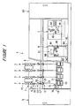
- a spinning machine 1 shown in Figure 1 includes a large number of spinning units 2 arranged in a line.
- the spinning machine 1 includes a yarn splicing vehicle 3, a doffing vehicle 4, a blower box 80, and a motor box 5.
- a housing 6 of the spinning machine 1 includes a rail 41 and a traveling route 86.
- the rail 41 and the traveling route 86 are arranged along a direction in which the spinning units 2 are arranged.
- the yarn splicing vehicle 3 can travel along the rail 41.
- the doffing vehicle 4 can travel along the traveling route 86.
- each of the spinning units 2 includes, as main components, a draft device 7, a spinning device 9, a yarn feeding device 11, a yarn slack eliminating device 12, and a winding device 13 arranged in this order from upstream to downstream.
- the draft device 7 is provided in the vicinity of an upper end of the housing 6 of the spinning machine 1.
- a fiber bundle 8 fed from the draft device 7 is spun by the spinning device 9.
- a spun yarn 10 discharged from the spinning device 9 is fed by the yarn feeding device 11, and the spun yarn 10 passes through a yarn clearer 52 described below and is then wound by the winding device 13.
- a package 45 is formed.
- the draft device 7 drafts a sliver 15 into a fiber bundle 8.
- the draft device 7 includes four rollers, that is, a back roller 16, a third roller 17, a middle roller 19, and a front roller 20.
- the middle roller 19 is provided with an apron belt 18.
- the configuration of the spinning device 9 is not illustrated in detail.
- the spinning machine 1 of the present embodiment adopts a pneumatic type that utilizes a whirling stream to generate the spun yarn 10 from the fiber bundle 8.
- the yarn feeding device 11 includes a delivery roller 39 and a nip roller 40.
- the delivery roller 39 is supported by the housing 6 of the spinning machine 1.
- the nip roller 40 is provided in contact with the delivery roller 39.
- the yarn feeding device 11 rotationally drives the delivery roller 39 using an electric motor (not shown in the drawings), with the spun yarn 10 discharged from the spinning device 9 sandwiched between the delivery roller 39 and the nip roller 40.
- the yarn feeding device 11 can thus feed the spun yarn 10 toward the winding device 13 side.
- a yarn clearer 52 is provided closer to a front surface side of the housing 6 of the spinning machine 1 and slightly downstream side of the yarn feeding device 11.
- the spun yarn 10 spun by the spinning device 9 passes through the yarn clearer 52 before being wound by the winding device 13.
- the yarn clearer 52 monitors the thickness of the traveling spun yarn 10. Upon detecting a yarn defect in the spun yarn 10, the yarn clearer 52 transmits a yarn defect detection signal to a unit controller (not shown in the drawings).
- the unit controller Upon receiving the yarn defect detection signal, the unit controller immediately cuts the spun yarn 10 using a cutter 57 and further stops the draft device 7, the spinning device 9, and the like. Furthermore, the unit controller sends a control signal to the yarn splicing vehicle 3 so that the yarn splicing vehicle 3 travels to the front of the appropriate spinning unit 2. The unit controller thereafter drives the spinning device 9 and the like again to allow the yarn spinning vehicle 3 to perform yarn splicing. Then, a spinning operation and a winding operation can be resumed.
- the yarn splicing vehicle 3 includes a splicer (splicing device) 43, a suction pipe 44, and a suction mouth 46.
- a splicer splicing device
- the suction pipe 44 sucks and catches a yarn end discharged from the spinning device 9, and guides the yarn end to the splicer 43.
- the suction mouth 46 sucks and catches a yarn end from a package 45 supported by the winding device 13, and guides the yarn end to the splicer 43.
- the splicer 43 splices the guided yarn ends together.
- the doffing vehicle 4 includes a doffing device 61.
- the doffing device 61 includes a cradle operating arm 90, a suction pipe 88, and a bunch winding arm 91.
- the cradle operating arm 90 is configured to be able to operate an arm 71 (described below) of the winding device 13.
- the suction pipe 88 is configured to be expandable.
- the suction pipe 88 is configured to suck and catch the yarn end discharged from the spinning device 9, and to guide the yarn end to an empty bobbin 48 installed on the winding device 13.
- the bunch winding arm 91 is configured to be able to fix the spun yarn 10 to the empty bobbin 48 by straight winding the yarn around the empty bobbin 48.
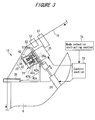
- the yarn slack eliminating device 12 is provided further downstream of the yarn clearer 52. As shown in Figure 3 , the yarn slack eliminating device 12 includes a yarn slack eliminating roller 21, a yarn hooking member 22, an upstream side guide 23, an air cylinder 24, an electric motor 25, a downstream side guide 26, and a control section 73.
- the yarn slack eliminating roller 21 includes a yarn slack eliminating roller main body 42 fixed to a motor shaft 25a of the electric motor 25.
- a side of the yarn slack eliminating roller main body 42 which has the yarn hooking member 22 is defined as a leading end, and a side thereof which is connected to the electric motor 25 is defined as a base end.
- an outer peripheral surface 42a of the yarn slack eliminating roller main body 42 includes a base end side taper portion 42b, a cylindrical portion 42c, and a leading end side taper portion 42d arranged in this order from the base end towards the leading end.
- the base end side taper portion 42b and the leading end side taper portion 42d are gently tapered such that an end surface side of each of the taper portions corresponds to a larger diameter side.
- the cylindrical portion 42c is shaped such that a leading end side thereof is slightly thinned.
- the cylindrical portion 42c is continuous with the taper portions 42b and 42c located on the opposite sides of the cylindrical portion 42c, with no step formed between the cylindrical portion 42c and each of the taper portions 42b and 42d.
- the yarn slack eliminating device 12 allows the yarn hooking member 22 to wind the spun yarn 10 from the spinning device 9 side, around an outer peripheral surface 42a of the yarn slack eliminating roller main body 42.
- the yarn slack eliminating device 12 allows the yarn hooking member 22 to unwind the spun yarn 10 wound and accumulated around the outer peripheral surface 42a, toward the winding device 13.
- the spun yarn 10 is wound around the yarn slack eliminating roller main body 42 for accumulation, the winding starts from the base end of the yarn slack eliminating roller main body 42.
- the unwinding starts from the leading end side of the yarn slack eliminating roller main body 42.
- the base end side taper portion 42b allows the supplied spun yarn 10 to smoothly move from a larger diameter portion to a smaller diameter portion of the outer peripheral surface 42a of the yarn slack eliminating roller main body 42 to reach the cylindrical portion 42c, located midway between the larger and smaller diameter portions.
- the spun yarn 10 can be orderly wound around the surface of the cylindrical portion 42c.
- the leading end side taper portion 42d has a function of preventing a slip-off phenomenon in which while the spun yarn 10 is being unwound, all of the wound spun yarn 10 slips off from the yarn slack eliminating roller main body 42 at one time.
- the leading end side taper portion 42d also has a function of winding back the spun yarn 10 from the smaller diameter portion towards the larger diameter portion on the end surface side of the yarn slack eliminating roller main body 42 to allow the spun yarn 10 to be smoothly drawn out.
- the yarn hooking member 22 located on the leading end side of the yarn slack eliminating roller 21, is located concentrically with the yarn slack eliminating roller 21. Moreover, the yarn hooking member 22 rotates integrally with or independently of the yarn slack eliminating roller 21 depending on conditions.
- the yarn hooking member 22 includes a flyer shaft 33 and a flyer 38.
- the flyer shaft 33 is supported so as to be rotatable relative to the yarn slack eliminating roller 21.
- the flyer 38 is secured to a leading end of the flyer shaft 33.
- a permanent magnet is attached to one of the flyer shaft 33 and the roller main body 42, whereas a magnetic hysteresis material is attached to the other. These magnetic means serve to generate a torque acting against the rotation of the yarn hooking member 22 relative to the yarn slack eliminating roller 21.
- the flyer 38 is configured to rotate integrally with the flyer shaft 33. Furthermore, the flyer 38 is shaped to be appropriately curved toward the outer peripheral surface 42a of the yarn slack eliminating roller main body 42. Thus, the flyer 38 can engage with the spun yarn 10 (can catch the spun yarn 10) to guide the spun yarn 10 to the outer peripheral surface of the yarn slack eliminating roller main body 42.
- the upstream side guide 23 is located slightly upstream side of the yarn slack eliminating roller 21.
- the upstream side guide 23 is provided so as to be movable between an advanced position and a retracted position by means of the air cylinder 24.
- the upstream side guide 23 is located at the advanced position (the position shown by a solid line in Figure 3 )
- the yarn path of the spun yarn 10 is held by the upstream side guide 23 so as to prevent the spun yarn 10 from being engaged with the yarn slack eliminating device 12.
- the yarn path is moved to a position where the spun yarn 10 engages with the yarn hooking member 22 of the yarn slack eliminating device 12 and is wound around the yarn slack eliminating roller 21.
- the winding device 13 includes a cradle arm 71 swingably supported around a support shaft 70.
- the cradle arm 71 can rotatably support the bobbin 48 so that the spun yarn 10 can be wound around the bobbin 48.
- the winding device 13 further includes a winding drum 72 and a traverse device 75.
- the winding drum 72 is configured to contact with and drive the bobbin 48 or an outer peripheral surface of the package 45 formed by winding the spun yarn 10 around the bobbin 48.
- the traverse device 75 includes a traverse guide 76 that can be engaged with the spun yarn 10. By driving the traverse guide 76 by a driving means (not illustrated in the drawings) to reciprocate the spun yarn 10 and driving the winding drum 72 by an electric motor (not illustrated in the drawings), the package 45 making contact with the winding drum 72 is rotated and the spun yarn 10 is wound while being traversed.
- Figure 1 shows that a cheese-shaped package is formed.
- the spinning machine 1 can form a cone-shaped package using the winding device 13.
- the yarn slack eliminating device 12 hooks the flyer 38 on the spun yarn 10 to wind the spun yarn 10 around the yarn slack eliminating roller 21.
- the yarn slack eliminating device 12 avoids slackening and detaining of the spun yarn 10, and adjusts winding tension.
- the yarn hooking member 22 is independently rotatable relative to the yarn slack eliminating roller 21, and the magnetic means applies the resistance torque acting in a direction in which the torque resists the rotation. Furthermore, the yarn slack eliminating roller 21 is rotated at a predetermined rotation speed by the electric motor 25.
- the yarn hooking member 22 rotates independently of the yarn slack eliminating roller 21 to unwind the spun yarn 10 from the yarn slack eliminating roller 21.
- the yarn hooking member 22 rotates integrally with the yarn slack eliminating roller 21 to wind the yarn around the yarn slack eliminating roller 21.
- the yarn slack eliminating device 12 operates to wind the spun yarn 10 when the tension of the spun yarn 10 decreases (when the spun yarn 10 is about to be slackened) and to unwind the spun yarn 10 when the tension of the spun yarn 10 increases.
- the yarn slack eliminating device 12 can thus avoid slackening of the spun yarn 10 to apply an appropriate tension to the spun yarn 10.
- the tension exerted on the spun yarn 10 is basically determined by a yarn feeding speed of the yarn feeding device 11 (a spinning speed of the spinning device 9) and a winding speed of the winding device 13. That is, when the winding speed is higher than the yarn feeding speed, a tension exerted on the spun yarn 10 increases. When the winding speed is lower than the yarn feeding speed, a tension exerted on the spun yarn 10 decreases. Since the yarn feeding device 11 normally feeds the spun yarn 10 at a constant yarn feeding speed (spinning speed), the tension exerted on the spun yarn 10 varies mainly depending on the winding speed of the winding device 13.
- the yarn slack eliminating device 12 also functions as a device which permits a variation in the winding speed which generates during the formation of the cone winding package and which stabilizes the winding tension.
- a feedback control is carried out on the cradle arm 71 in accordance with a signal from an accumulated yarn amount sensing means (not shown in the drawings).
- the rotation speed of the winding drum 72 is set such that for normal winding, in order to apply an appropriate winding tension to the spun yarn 10, the winding speed is slightly higher than the yarn feeding speed of the yarn feeding device 11 (a spinning speed of the spinning device 9).
- the spun yarn 10 wound around the yarn slack eliminating roller 21 is gradually unwound to reduce the amount of an accumulated yarn.
- the accumulated yarn amount sensing means is provided on the outer peripheral surface of the yarn slack eliminating roller 21.
- the unit controller of the spinning unit 2 controls a cradle lifter (not shown in the drawings) such that the cradle arm 71 is pivotably moved leftward in Figure 2 .
- the package 45 is thus separated from the winding drum 72. Consequently, the package 45 loses the driving force and continues inertial rotation. However, the winding speed of the package 45 decreases gradually.
- the unit controller pivotably moves the cradle arm 71 rightward in Figure 2 to contact the package 45 with the winding drum 72.
- the winding speed is recovered, and the spun yarn 10 is unwound from the yarn slack eliminating roller 21 as described above.
- the winding speed can thus be adjusted by using the cradle lifter to swing the cradle arm 71 to contact the package 45 with the winding drum 72 or separate the package 45 from the winding drum 72. Then, the winding speed is controlled while detecting the amount of yarn accumulated around the yarn slack eliminating roller 21 and carrying out the feedback control. As a result, at least a predetermined amount of spun yarn 10 can always be accumulated on the yarn slack eliminating roller 21.
- the above-described function of stabilizing the winding tension is not necessarily required, because in this case, variation in the winding speed depending on the traverse position is not significant. Rather, in view of a decrease in component lifetime and energy consumption associated with the operation of the electric motor 25 and the cradle lifter, it is preferable to avoid the yarn slack eliminating device 12 from being operated at all times.
- the spun yarn 10 is likely to be entangled with the rotating flyer 38. The spun yarn 10 entangled with the flyer 38 may damage the devices, or the entangled spun yarn 10 may be mix into the package to degrade the package quality. Therefore, also in this respect, it is preferable to avoid the yarn slack eliminating device 12 from being operated at all times.
- the yarn slack eliminating device 12 needs to be operated from the beginning of spinning by the spinning device 9 until the winding device 13 starts winding, in order to prevent the spun yarn 10 from being slackened or detained. Examples of such a case include yarn splicing and doffing.
- control section 73 of the spinning machine 1 is configured to be switchable between a first mode in which the yarn slack eliminating device 12 is switchably operated and stopped, and a second mode in which the yarn slack eliminating device 12 is always operated.
- the spinning machine 1 according to the present embodiment includes a mode selection instructing section 74 composed of, for example, a switch and a button. When an operator operates the mode selection instructing section 74, the mode of the control section 73 can be switched. However, the mode may be automatically selected by determining the package shape.
- the yarn slack eliminating device 12 operates to eliminate the slack of the spun yarn 10 at least during a winding preparation time (from the beginning of spinning by the spinning device 9 until the winding device 13 starts winding) but is not operated for the rest of the time.
- the yarn slack eliminating device 12 is operated all the time including the winding preparation time to uniformize the winding tension of the spun yarn 10.
- control section 73 of the spinning machine 1 controls the yarn slack eliminating device 12 to be operated during yarn splicing. This control will be described below in detail.
- the control section 73 controls the air cylinder 24 to move the upstream side guide 23 to the advanced position.
- the yarn path is thus held so that the spun yarn 10 does not engage with the yarn slack eliminating device 12.
- the control section 73 controls to stop the rotation of the electric motor 25.
- the yarn clearer 52 detects a yarn defect in the spun yarn 10 in a certain spinning unit 2 during spinning. Then, the unit controller of the spinning unit 2 immediately cuts the spun yarn 10 using the cutter 57. Almost simultaneously with the yarn cutting, the unit controller stops the spinning device 9 and further stops rotation of the back roller 16 and third roller 17 of the draft device 7. The fiber bundle 8 is tearingly cut between the stopped third roller 17 and the rotating middle roller 19, and a part of the spun yarn 10 located downstream from the cut portion is sucked and removed by suction means (not shown in the drawings). Furthermore, the control section 73 controls the cradle lifter to pivotably rotate the cradle arm 71 leftward in Figure 2 . The package 45 is thus separated from the winding drum 72 to stop rotation of the package 45.
- the unit controller controls the yarn splicing vehicle 3 to travel to a position where the yarn splicing vehicle 3 is positioned facing the spinning unit 2.
- the control section 73 then operates the electric motor 25 at an appropriate timing to start rotating the yarn slack eliminating roller 21.
- the yarn splicing vehicle 3 pivotably moves the suction pipe 44 upward, while pivotably moving the suction mouth 46 downward. Then, the yarn splicing vehicle 3 catches the yarn end from the spinning device 9 using the suction pipe 44, while catching the yarn end on the package 45 side using the suction mouth 46. The yarn splicing vehicle 3 then guides the respective yarn ends to the splicer 43 for yarn splicing.
- the above-descried series of operations allow the spun yarn 10 spun by the spinning device 9 to be wound by the winding device 13.
- the control section 73 controls the air cylinder 24 to move the upstream side guide 23 to the retracted position, and the yarn path of the spun yarn 10 is thus moved to a position where the yarn path of the spun yarn 10 can be engaged with the rotating flyer 38. Accordingly, the spun yarn 10 is wound around the continuously rotating yarn slack eliminating roller 21 to prevent the spun yarn 10 from being slackened or detained during a yarn splicing operation.
- the unit controller pivotably moves the cradle arm 71 rightward in Figure 2 , and the package 45 is thus contacted with the winding drum 72 to allow yarn winding to be resumed. Accordingly, the winding tension applies to the spun yarn 10, which is thus gradually unwound from the yarn slack eliminating roller 21.
- the control section 73 controls the air cylinder 24 to move the upstream side guide 23 to the advanced position again.
- the spun yarn 10 is thus prevented from being engaged with the flyer 38.
- the control section 73 controls rotation of the electric motor 25. Accordingly, energy efficiency is increased, and duration of the yarn slack eliminating device 12 increases. Additionally, the spun yarn 10 is prevented from traveling while rubbing against the flyer 38 to degrade the quality thereof.
- the yarn splicing operation is performed not only when the yarn clearer 52 detects a yarn defect and cuts the spun yarn 10 using the cutter 57 but also when the yarn clearer 52 detects that the spun yarn 10 has been broken (yarn breakage) for some reason. Even in the case of the yarn breakage, the control of the yarn slack eliminating device 12 in the first mode is performed in exactly the same manner as described above.
- control section 73 of the spinning machine 1 performs control such that the yarn slack eliminating device 12 is operated also during doffing. This control will be described below in detail.
- the unit controller stops the spinning device 9, and also stops the back roller 16 and third roller 17 of the draft device 7. Almost at the same time, the unit controller pivotably moves the cradle arm 71 of the winding device 13 leftward in Figure 2 to separate the full package 45 from the winding drum 72, and stops rotation of the winding drum 72.
- control section 73 controls the doffing vehicle 4 to travel to the front of the spinning unit 2.
- the control section 73 then operates the electric motor 25 at an appropriate timing to start rotating the yarn slack eliminating roller 21.
- the doffing vehicle 4 uses the cradle operating arm 90 to appropriately operate the cradle arm 71, and the doffing vehicle 4 then uses a package removing means (not shown in the drawings) to remove the full package 45 from the cradle arm 71.
- the removed full package 45 rolls down an inclined floor 94 formed in the doffing vehicle 4, and the full package 45 then falls onto a shelf 96 formed like a groove, where the full package 45 comes to rest.
- an empty bobbin supply means (not shown in the drawings) provided in the doffing vehicle 4 sets an empty bobbin 48 in the cradle arm 71.
- the unit controller of the spinning unit 2 resumes driving the draft device 7 and the spinning device 9. Furthermore, almost at the same time, the suction pipe 88 expands upward. The suction pipe 88 then sucks and catches the yarn end of the spun yarn 10 discharged from the spinning device 9. The suction pipe 88 thereafter guides the yarn end to the vicinity of the empty bobbin 48. Subsequently, a bunch winding arm 91 performs a bunch winding operation and attaches the yarn end to the empty bobbin 48. The above-described series of operations allows the spun yarn 10 spun by the spinning device 9 to be wound by the winding device 13.
- the control section 73 controls the air cylinder 24 to move the upstream side guide 23 to the retracted position.
- the spun yarn 10 is wound around the yarn slack eliminating roller 21 to prevent the spun yarn 10 from being slackened during a doffing operation.
- the doffing vehicle 4 uses the cradle operating arm 90 to pivotably move the cradle arm 71 rightward in Figure 2 , and the doffing vehicle 4 contacts the bobbin 48 subjected to the bunch winding with the winding drum 72 to start winding the spun yarn 10. This applies winding tension to the spun yarn 10, which is thus gradually unwound from the yarn slack eliminating roller 21.
- control section 73 controls the air cylinder 24 to move the upstream side guide 23 to the advanced position again.
- the spun yarn 10 is thus prevented from engaging with the flyer 38.
- control section 73 stops rotation of the electric motor 25.
- the control section 73 when the control section 73 operates in the first mode, the yarn slack eliminating device 12 operates only during the required period from the beginning of spinning until yarn winding is started. This is advantageous in terms of energy saving, the durability of the devices, production efficiency, and the like. Meanwhile, when the tension varies significantly depending on the traverse position as in the case of winding a cone winding package, the control section 73 is operated in the second mode to always operate the yarn slack eliminating device 12. The winding tension can thus be appropriately controlled to form the package 45 from which the yarn can be properly unwound.
- the spinning machine 1 includes the spinning device 9, the winding device 13, the yarn slack eliminating device 12, and the control section 73.
- the spinning device 9 spins the yarn.
- the winding device 13 winds the spun yarn to form the package.
- the yarn slack eliminating device 12 has the yarn slack eliminating roller 21 and the yarn hooking member 22.
- the control section 73 controls operation of the yarn slack eliminating device 12.
- the control section 73 can switch between a first mode in which the yarn slack eliminating device 12 is switchably operated and stopped, and a second mode in which the yarn slack eliminating device 12 is always operated.
- the yarn slack eliminating device 12 is operated, at least, during the operation time for the operation (for example, the yarn splicing operation or the doffing operation) of allowing the yarn spun by the spinning device 9 to be wound by the winding device 13.
- the first mode and the second mode can be switched as required.
- This allows the yarn slack eliminating device 12 to be operated only when required, enabling energy consumption to be saved. Furthermore, the durability of devices such as the yarn slack eliminating device 12 and the cradle lifter is improved to allow the devices to last longer. Additionally, the yarn slack eliminating device 12 is prevented from being unnecessarily operated, thus reducing the likelihood of the occurrence of the problem associated with the winding of the yarn around the flyer 38.
- the spinning machine 1 further includes the splicer 43.
- the control section 73 performs control such that in the first mode, the yarn slack eliminating device 12 is operated at least during a yarn splicing operation of the splicer 43.
- the yarn slack eliminating device 12 is operated to enable the spun yarn 10 to be prevented from being slackened.
- the yarn splicing operation can therefore be smoothly performed.
- the spinning machine 1 further includes the doffing device 61.
- the control section 73 performs control such that in the first mode, the yarn slack eliminating device 12 is operated at least during a doffing operation of the doffing device 61.
- the yarn slack eliminating device 12 is operated to enable the spun yarn 10 to be prevented from being slackened.
- the doffing operation can therefore be smoothly performed.
- the winding device 13 is configured to be able to form a cheese winding package.
- the yarn slack eliminating device 12 is not required to be operated at all times. Consequently, the operation in the first mode allows the device to be efficiently operated.
- the winding device 13 is configured to be able to form a cone winding package.
- the unit section 73 may be configured as a part of the function of the unit controller of the spinning unit 2.
- the means for generating the resistance torque which acts against the relative rotation between the yarn hooking member 22 and the yarn slack eliminating roller 21, may be, instead of the magnetic means, an electromagnetic means based on an electromagnet, a mechanical means based on a frictional force, or the like.
- an arrangement may be provided in which the splicer 43 is provided in each of the spinning units 2.
- an arrangement may be provided in which the doffing vehicle 4 includes the doffing device 61, an arrangement may be provided in which the doffing device is installed in each of the spinning units 2.
Landscapes
- Engineering & Computer Science (AREA)
- Textile Engineering (AREA)
- Mechanical Engineering (AREA)
- Spinning Or Twisting Of Yarns (AREA)
- Forwarding And Storing Of Filamentary Material (AREA)
Abstract
An object of the present invention is to provide a spinning machine which enables proper energy saving and which offers a proper durability and a high production efficiency. In the spinning machine, a control section 73 controls operation of a yarn slack eliminating device 12. The control section 73 can switch between a first mode in which the yarn slack eliminating device 12 is switchably operated and stopped, and a second mode in which the yarn slack eliminating device 12 is always operated. In the first mode, the yarn slack eliminating device 12 is operated during an operation time for an operation (for example, a yarn splicing operation or a doffing operation) of allowing a yarn spun by a spinning device to be wound by a winding device.
Description
- The present invention relates to a spinning machine including a yarn slack eliminating device.
- With a conventional high-speed spinning machine such as a pneumatic spinning machine which winds a spun yarn to form a package, when carrying out a yarn splicing operation to splice the spun yarn and a yarn at the package side, or when carrying out a doffing operation to attach the spun yarn to an empty bobbin, a winding operation at the package side is stopped. However, even with the winding stopped, the yarn is continuously fed from a spinning device. Thus, the yarn needs to be prevented from being slackened or detained.
- In view of this, the Unexamined Japanese Patent Application Publication (Tokkai) No.
2006-306588 - When forming a cone winding package by a spinning machine, the tension is likely to vary depending on a traverse position. Thus, the yarn slack eliminating device is effective for controlling the tension. However, for a cheese winding package, since the tension variation depending on the traverse position is insignificant, the necessity of the tension control is small. It is thus sufficient to be able to prevent the yarn from being detained.
- Conversely, when the yarn slack eliminating device is operated in spite of the insignificant effect thereof, power is wasted and the durability of the yarn hooking member, the electric motor, and the like is degraded. Furthermore, the winding speed on the package side needs to be reduced depending on the situation so as to keep the yarn wound around the yarn slack eliminating roller. This also reduces the durability of the mechanism. Moreover, the yarn is often entangled with the rotating yarn hooking member. This may disadvantageously reduce productivity.
- The present invention has been made in view of the above-described circumstances. An object of the present invention is to provide a spinning machine that operates the yarn slack eliminating device only when required.
- According to an aspect of the present invention, a spinning machine includes a spinning device, a winding device, a yarn slack eliminating device, and a control section. The spinning device spins a yarn. The winding device winds the spun yarn to form a package. The yarn slack eliminating device has a yarn slack eliminating roller and a yarn hooking member. The control section controls operation of the yarn slack eliminating device. The control section can switch between a first mode in which the yarn slack eliminating device is switchably operated and stopped, and a second mode in which the yarn slack eliminating device is always operated. In the first mode, the yarn slack eliminating device is operated at least during an operation time for an operation of allowing the yarn spun by the spinning device to be wound by the winding device.
- Thus, the first mode and the second mode can be switched as required.
This allows the yarn slack eliminating device to be operated only when required, enabling energy consumption to be saved. Furthermore, the durability of devices is improved to allow the devices to last longer. Additionally, the yarn slack eliminating device is prevented from being unnecessarily operated, thus reducing the likelihood of the occurrence of the problem associated with the winding of the yarn around the yarn slack eliminating device. - Preferably, the spinning machine further includes a yarn splicing device. The control section performs control such that in the first mode, the yarn slack eliminating device is operated at least during a yarn splicing operation of the yarn splicing device.
- Thus, during the yarn splicing, the yarn slack eliminating device is operated to enable the yarn to be prevented from being slackened, and the yarn splicing operation can therefore be smoothly performed.
- Preferably, the spinning machine further includes a doffing device.
The control section performs control such that in the first mode, the yarn slack eliminating device is operated at least during a doffing operation of the doffing device. - Thus, during the doffing, the yarn slack eliminating device is operated to enable the yarn to be prevented from being slackened, and the doffing operation can therefore be smoothly performed.
- In the spinning machine, the winding device can preferably form a cheese winding package.
- That is, for the cheese winding, the yarn slack eliminating device need not always be operated. Thus, operating the yarn slack eliminating device in the first mode is advantageous in terms of energy saving and durability.
- In the spinning machine, the winding device can preferably form a cone winding package.
- That is, for the cone winding, by operating the yarn slack eliminating device in the second mode, in which the yarn slack eliminating device is always operated, a possible variation in winding tension can be prevented to allow formation of a high-quality package.
- Other features, elements, processes, steps, characteristics and advantages of the present invention will become more apparent from the following detailed description of preferred embodiments of the present invention with reference to the attached drawings.
-
-
Figure 1 is a front view of a spinning machine according to an embodiment of the present invention. -
Figure 2 is a vertically sectional side view of a spinning machine. -
Figure 3 is a vertically sectional side view of a yarn slack eliminating device. - A spinning machine according to an embodiment of the present invention will be described with reference to the drawings. In the specification, "upstream" and "downstream" refer to an upstream side and a downstream side, respectively, in a direction in which a yarn travels during spinning.
- A spinning machine 1 shown in
Figure 1 includes a large number ofspinning units 2 arranged in a line. The spinning machine 1 includes a yarn splicing vehicle 3, a doffing vehicle 4, ablower box 80, and amotor box 5. - A
housing 6 of the spinning machine 1 includes arail 41 and atraveling route 86. Therail 41 and thetraveling route 86 are arranged along a direction in which the spinningunits 2 are arranged. The yarn splicing vehicle 3 can travel along therail 41. The doffing vehicle 4 can travel along thetraveling route 86. - As shown in
Figure 1 , each of thespinning units 2 includes, as main components, adraft device 7, aspinning device 9, ayarn feeding device 11, a yarnslack eliminating device 12, and awinding device 13 arranged in this order from upstream to downstream. Thedraft device 7 is provided in the vicinity of an upper end of thehousing 6 of the spinning machine 1. A fiber bundle 8 fed from thedraft device 7 is spun by thespinning device 9. Aspun yarn 10 discharged from thespinning device 9 is fed by theyarn feeding device 11, and thespun yarn 10 passes through a yarn clearer 52 described below and is then wound by thewinding device 13. Thus, apackage 45 is formed. - The
draft device 7 drafts asliver 15 into a fiber bundle 8. As shown inFigure 2 , thedraft device 7 includes four rollers, that is, aback roller 16, athird roller 17, amiddle roller 19, and a front roller 20. Themiddle roller 19 is provided with an apron belt 18. - The configuration of the
spinning device 9 is not illustrated in detail. The spinning machine 1 of the present embodiment adopts a pneumatic type that utilizes a whirling stream to generate the spunyarn 10 from the fiber bundle 8. - The
yarn feeding device 11 includes adelivery roller 39 and anip roller 40. Thedelivery roller 39 is supported by thehousing 6 of the spinning machine 1. Thenip roller 40 is provided in contact with thedelivery roller 39. Theyarn feeding device 11 rotationally drives thedelivery roller 39 using an electric motor (not shown in the drawings), with the spunyarn 10 discharged from thespinning device 9 sandwiched between thedelivery roller 39 and thenip roller 40. Theyarn feeding device 11 can thus feed the spunyarn 10 toward the windingdevice 13 side. - A
yarn clearer 52 is provided closer to a front surface side of thehousing 6 of the spinning machine 1 and slightly downstream side of theyarn feeding device 11. The spunyarn 10 spun by thespinning device 9 passes through theyarn clearer 52 before being wound by the windingdevice 13. Theyarn clearer 52 monitors the thickness of the traveling spunyarn 10. Upon detecting a yarn defect in the spunyarn 10, theyarn clearer 52 transmits a yarn defect detection signal to a unit controller (not shown in the drawings). - Upon receiving the yarn defect detection signal, the unit controller immediately cuts the spun
yarn 10 using acutter 57 and further stops thedraft device 7, thespinning device 9, and the like. Furthermore, the unit controller sends a control signal to the yarn splicing vehicle 3 so that the yarn splicing vehicle 3 travels to the front of theappropriate spinning unit 2. The unit controller thereafter drives thespinning device 9 and the like again to allow the yarn spinning vehicle 3 to perform yarn splicing. Then, a spinning operation and a winding operation can be resumed. - As shown in
Figures 1 and2 , the yarn splicing vehicle 3 includes a splicer (splicing device) 43, asuction pipe 44, and asuction mouth 46. When yarn breakage or yarn cut occurs in onespinning unit 2, the yarn spicing vehicle 3 travels on therail 41 to theappropriate spinning unit 2, and is then stopped. While moving pivotably around a shaft in a vertical direction, thesuction pipe 44 sucks and catches a yarn end discharged from thespinning device 9, and guides the yarn end to thesplicer 43. While moving pivotably around a shaft in the vertical direction, thesuction mouth 46 sucks and catches a yarn end from apackage 45 supported by the windingdevice 13, and guides the yarn end to thesplicer 43. Thesplicer 43 splices the guided yarn ends together. - The doffing vehicle 4 includes a doffing
device 61. The doffingdevice 61 includes acradle operating arm 90, asuction pipe 88, and abunch winding arm 91. When thepackage 45 is fully wound in acertain spinning unit 2, the doffing device 4 travels on the travelingroute 86 tosuch spinning unit 2, and is then stopped. Thecradle operating arm 90 is configured to be able to operate an arm 71 (described below) of the windingdevice 13. Thesuction pipe 88 is configured to be expandable. Thesuction pipe 88 is configured to suck and catch the yarn end discharged from thespinning device 9, and to guide the yarn end to anempty bobbin 48 installed on the windingdevice 13. Thebunch winding arm 91 is configured to be able to fix the spunyarn 10 to theempty bobbin 48 by straight winding the yarn around theempty bobbin 48. - The yarn
slack eliminating device 12 is provided further downstream of theyarn clearer 52. As shown inFigure 3 , the yarnslack eliminating device 12 includes a yarnslack eliminating roller 21, ayarn hooking member 22, anupstream side guide 23, anair cylinder 24, anelectric motor 25, adownstream side guide 26, and acontrol section 73. - The yarn
slack eliminating roller 21 includes a yarn slack eliminating rollermain body 42 fixed to amotor shaft 25a of theelectric motor 25. A side of the yarn slack eliminating rollermain body 42 which has theyarn hooking member 22 is defined as a leading end, and a side thereof which is connected to theelectric motor 25 is defined as a base end. Then, an outerperipheral surface 42a of the yarn slack eliminating rollermain body 42 includes a base endside taper portion 42b, acylindrical portion 42c, and a leading endside taper portion 42d arranged in this order from the base end towards the leading end. The base endside taper portion 42b and the leading endside taper portion 42d are gently tapered such that an end surface side of each of the taper portions corresponds to a larger diameter side. Thecylindrical portion 42c is shaped such that a leading end side thereof is slightly thinned. Moreover, thecylindrical portion 42c is continuous with thetaper portions cylindrical portion 42c, with no step formed between thecylindrical portion 42c and each of thetaper portions - During a yarn splicing operation of the yarn splicing vehicle 3 and a doffing operation of the doffing device 4, the yarn
slack eliminating device 12 allows theyarn hooking member 22 to wind the spunyarn 10 from thespinning device 9 side, around an outerperipheral surface 42a of the yarn slack eliminating rollermain body 42. When the yarn splicing operation or the doffing operation is completed, the yarnslack eliminating device 12 allows theyarn hooking member 22 to unwind the spunyarn 10 wound and accumulated around the outerperipheral surface 42a, toward the windingdevice 13. When the spunyarn 10 is wound around the yarn slack eliminating rollermain body 42 for accumulation, the winding starts from the base end of the yarn slack eliminating rollermain body 42. When the spunyarn 10 is unwound from the yarn slack eliminating rollermain body 42, the unwinding starts from the leading end side of the yarn slack eliminating rollermain body 42. - The base end
side taper portion 42b allows the supplied spunyarn 10 to smoothly move from a larger diameter portion to a smaller diameter portion of the outerperipheral surface 42a of the yarn slack eliminating rollermain body 42 to reach thecylindrical portion 42c, located midway between the larger and smaller diameter portions. Thus, the spunyarn 10 can be orderly wound around the surface of thecylindrical portion 42c. Furthermore, the leading endside taper portion 42d has a function of preventing a slip-off phenomenon in which while the spunyarn 10 is being unwound, all of the wound spunyarn 10 slips off from the yarn slack eliminating rollermain body 42 at one time. The leading endside taper portion 42d also has a function of winding back the spunyarn 10 from the smaller diameter portion towards the larger diameter portion on the end surface side of the yarn slack eliminating rollermain body 42 to allow the spunyarn 10 to be smoothly drawn out. - As shown in
Figure 3 , theyarn hooking member 22, located on the leading end side of the yarnslack eliminating roller 21, is located concentrically with the yarnslack eliminating roller 21. Moreover, theyarn hooking member 22 rotates integrally with or independently of the yarnslack eliminating roller 21 depending on conditions. Specifically, theyarn hooking member 22 includes aflyer shaft 33 and aflyer 38. Theflyer shaft 33 is supported so as to be rotatable relative to the yarnslack eliminating roller 21. Theflyer 38 is secured to a leading end of theflyer shaft 33. - A permanent magnet is attached to one of the
flyer shaft 33 and the rollermain body 42, whereas a magnetic hysteresis material is attached to the other. These magnetic means serve to generate a torque acting against the rotation of theyarn hooking member 22 relative to the yarnslack eliminating roller 21. - The
flyer 38 is configured to rotate integrally with theflyer shaft 33. Furthermore, theflyer 38 is shaped to be appropriately curved toward the outerperipheral surface 42a of the yarn slack eliminating rollermain body 42. Thus, theflyer 38 can engage with the spun yarn 10 (can catch the spun yarn 10) to guide the spunyarn 10 to the outer peripheral surface of the yarn slack eliminating rollermain body 42. - The
upstream side guide 23 is located slightly upstream side of the yarnslack eliminating roller 21. Theupstream side guide 23 is provided so as to be movable between an advanced position and a retracted position by means of theair cylinder 24. When theupstream side guide 23 is located at the advanced position (the position shown by a solid line inFigure 3 ), the yarn path of the spunyarn 10 is held by theupstream side guide 23 so as to prevent the spunyarn 10 from being engaged with the yarnslack eliminating device 12. When theupstream side guide 23 is moved to the retracted position (the position shown by a dashed line inFigure 3 ), the yarn path is moved to a position where the spunyarn 10 engages with theyarn hooking member 22 of the yarnslack eliminating device 12 and is wound around the yarnslack eliminating roller 21. - As shown in
Figure 2 , the windingdevice 13 includes acradle arm 71 swingably supported around asupport shaft 70. Thecradle arm 71 can rotatably support thebobbin 48 so that the spunyarn 10 can be wound around thebobbin 48. - The winding
device 13 further includes a windingdrum 72 and atraverse device 75. The windingdrum 72 is configured to contact with and drive thebobbin 48 or an outer peripheral surface of thepackage 45 formed by winding the spunyarn 10 around thebobbin 48. Furthermore, thetraverse device 75 includes atraverse guide 76 that can be engaged with the spunyarn 10. By driving thetraverse guide 76 by a driving means (not illustrated in the drawings) to reciprocate the spunyarn 10 and driving the windingdrum 72 by an electric motor (not illustrated in the drawings), thepackage 45 making contact with the windingdrum 72 is rotated and the spunyarn 10 is wound while being traversed. -
Figure 1 shows that a cheese-shaped package is formed. However, the spinning machine 1 can form a cone-shaped package using the windingdevice 13. - Next, the operation of the spinning machine 1 configured as described above will be described.
- First, the operation of the yarn
slack eliminating device 12 will be described. - The yarn
slack eliminating device 12 hooks theflyer 38 on the spunyarn 10 to wind the spunyarn 10 around the yarnslack eliminating roller 21. Thus, the yarnslack eliminating device 12 avoids slackening and detaining of the spunyarn 10, and adjusts winding tension. - As described above, the
yarn hooking member 22 is independently rotatable relative to the yarnslack eliminating roller 21, and the magnetic means applies the resistance torque acting in a direction in which the torque resists the rotation. Furthermore, the yarnslack eliminating roller 21 is rotated at a predetermined rotation speed by theelectric motor 25. When theflyer 38 is engaged with the spunyarn 10, in case the tension exerted on the spunyarn 10 is strong enough to overcome the resistance torque, theyarn hooking member 22 rotates independently of the yarnslack eliminating roller 21 to unwind the spunyarn 10 from the yarnslack eliminating roller 21. In contrast, in case the tension exerted on the spunyarn 10 is weak, theyarn hooking member 22 rotates integrally with the yarnslack eliminating roller 21 to wind the yarn around the yarnslack eliminating roller 21. - As described above, the yarn
slack eliminating device 12 operates to wind the spunyarn 10 when the tension of the spunyarn 10 decreases (when the spunyarn 10 is about to be slackened) and to unwind the spunyarn 10 when the tension of the spunyarn 10 increases. The yarnslack eliminating device 12 can thus avoid slackening of the spunyarn 10 to apply an appropriate tension to the spunyarn 10. - The tension exerted on the spun
yarn 10 is basically determined by a yarn feeding speed of the yarn feeding device 11 (a spinning speed of the spinning device 9) and a winding speed of the windingdevice 13. That is, when the winding speed is higher than the yarn feeding speed, a tension exerted on the spunyarn 10 increases. When the winding speed is lower than the yarn feeding speed, a tension exerted on the spunyarn 10 decreases. Since theyarn feeding device 11 normally feeds the spunyarn 10 at a constant yarn feeding speed (spinning speed), the tension exerted on the spunyarn 10 varies mainly depending on the winding speed of the windingdevice 13. - When the winding
device 13 winds the spunyarn 10 into a cone winding package, since the winding speed varies between the larger diameter side and smaller diameter side of the package, the yarn tension is varied by traversing performed by thetraverse device 75. However, such a variation in yarn tension can be appropriately absorbed by the yarnslack eliminating device 12. - The present embodiment will be described below in detail. That is, suppose that during a winding process of a cone winding package in the spinning machine 1, the spun
yarn 10 is traversed towards the larger diameter side of the package and both the winding speed and the yarn tension increase. However, accompanying the increase in yarn tension, the torque causing the spunyarn 10 to rotate theyarn hooking member 22 relative to the yarnslack eliminating roller 21 also increases. Therefore, an amount of the spunyarn 10 unwound from the yarnslack eliminating roller 21 increases. As a result, the increased yarn tension can be decreased. - In contrast, when the spun
yarn 10 is traversed towards the smaller diameter side of the package and the winding speed is decreased, the yarn tension decreases. However, the torque exerted on theyarn hooking member 22 by the spunyarn 10 also decreases accompanying the decrease in the yarn tension. Thus, the amount of spunyarn 10 accumulated on the yarnslack eliminating roller 21 increases. Therefore, the decreased yarn tension can be recovered. - As described above, the yarn
slack eliminating device 12 also functions as a device which permits a variation in the winding speed which generates during the formation of the cone winding package and which stabilizes the winding tension. - To provide the function of stabilizing the winding tension, a given amount of spun
yarn 10 needs to be kept wound around the yarnslack eliminating roller 21. Thus, in the present embodiment, a feedback control is carried out on thecradle arm 71 in accordance with a signal from an accumulated yarn amount sensing means (not shown in the drawings). - Specifically, the rotation speed of the winding
drum 72 is set such that for normal winding, in order to apply an appropriate winding tension to the spunyarn 10, the winding speed is slightly higher than the yarn feeding speed of the yarn feeding device 11 (a spinning speed of the spinning device 9). Thus, the spunyarn 10 wound around the yarnslack eliminating roller 21 is gradually unwound to reduce the amount of an accumulated yarn. - The accumulated yarn amount sensing means is provided on the outer peripheral surface of the yarn
slack eliminating roller 21. When the accumulated yarn amount sensing means detects that the amount of yarn accumulated is equal to or smaller than a predetermined value, the unit controller of thespinning unit 2 controls a cradle lifter (not shown in the drawings) such that thecradle arm 71 is pivotably moved leftward inFigure 2 . Thepackage 45 is thus separated from the windingdrum 72. Consequently, thepackage 45 loses the driving force and continues inertial rotation. However, the winding speed of thepackage 45 decreases gradually. - As a result, the amount of yarn accumulated on the yarn
slack eliminating roller 21 is recovered, and the accumulated yarn amount sensing means eventually detects that the accumulated amount of spunyarn 10 is equal to or larger than the predetermined value. Then, the unit controller pivotably moves thecradle arm 71 rightward inFigure 2 to contact thepackage 45 with the windingdrum 72.
Thus, the winding speed is recovered, and the spunyarn 10 is unwound from the yarnslack eliminating roller 21 as described above. - The winding speed can thus be adjusted by using the cradle lifter to swing the
cradle arm 71 to contact thepackage 45 with the windingdrum 72 or separate thepackage 45 from the windingdrum 72. Then, the winding speed is controlled while detecting the amount of yarn accumulated around the yarnslack eliminating roller 21 and carrying out the feedback control. As a result, at least a predetermined amount of spunyarn 10 can always be accumulated on the yarnslack eliminating roller 21. - Meanwhile, to form, for example, a cheese winding package, the above-described function of stabilizing the winding tension is not necessarily required, because in this case, variation in the winding speed depending on the traverse position is not significant. Rather, in view of a decrease in component lifetime and energy consumption associated with the operation of the
electric motor 25 and the cradle lifter, it is preferable to avoid the yarnslack eliminating device 12 from being operated at all times. Furthermore, the spunyarn 10 is likely to be entangled with the rotatingflyer 38. The spunyarn 10 entangled with theflyer 38 may damage the devices, or the entangled spunyarn 10 may be mix into the package to degrade the package quality. Therefore, also in this respect, it is preferable to avoid the yarnslack eliminating device 12 from being operated at all times. - However, even when winding a cheese shaped package, the yarn
slack eliminating device 12 needs to be operated from the beginning of spinning by thespinning device 9 until the windingdevice 13 starts winding, in order to prevent the spunyarn 10 from being slackened or detained. Examples of such a case include yarn splicing and doffing. - Thus, the
control section 73 of the spinning machine 1 according to the present embodiment is configured to be switchable between a first mode in which the yarnslack eliminating device 12 is switchably operated and stopped, and a second mode in which the yarnslack eliminating device 12 is always operated. The spinning machine 1 according to the present embodiment includes a modeselection instructing section 74 composed of, for example, a switch and a button. When an operator operates the modeselection instructing section 74, the mode of thecontrol section 73 can be switched. However, the mode may be automatically selected by determining the package shape. - In the first mode, the yarn
slack eliminating device 12 operates to eliminate the slack of the spunyarn 10 at least during a winding preparation time (from the beginning of spinning by thespinning device 9 until the windingdevice 13 starts winding) but is not operated for the rest of the time. In the second mode, the yarnslack eliminating device 12 is operated all the time including the winding preparation time to uniformize the winding tension of the spunyarn 10. - In the first mode, the
control section 73 of the spinning machine 1 according to the present embodiment controls the yarnslack eliminating device 12 to be operated during yarn splicing. This control will be described below in detail. - First, in the first mode, during the normal spinning, the
control section 73 controls theair cylinder 24 to move theupstream side guide 23 to the advanced position. The yarn path is thus held so that the spunyarn 10 does not engage with the yarnslack eliminating device 12. Furthermore, during the normal spinning, thecontrol section 73 controls to stop the rotation of theelectric motor 25. Thus, energy required for the yarnslack eliminating device 12 and the cradle lifter can be saved, and duration of the yarnslack eliminating device 12 and the cradle lifter can be extended. Moreover, the spunyarn 10 is unlikely to be entangled with theflyer 38. In addition, it is not necessary to adjust the winding speed by swinging thecradle arm 71. As a result, energy efficiency and duration can further be increased. - Suppose that the
yarn clearer 52 detects a yarn defect in the spunyarn 10 in acertain spinning unit 2 during spinning. Then, the unit controller of thespinning unit 2 immediately cuts the spunyarn 10 using thecutter 57. Almost simultaneously with the yarn cutting, the unit controller stops thespinning device 9 and further stops rotation of theback roller 16 andthird roller 17 of thedraft device 7. The fiber bundle 8 is tearingly cut between the stoppedthird roller 17 and the rotatingmiddle roller 19, and a part of the spunyarn 10 located downstream from the cut portion is sucked and removed by suction means (not shown in the drawings). Furthermore, thecontrol section 73 controls the cradle lifter to pivotably rotate thecradle arm 71 leftward inFigure 2 . Thepackage 45 is thus separated from the windingdrum 72 to stop rotation of thepackage 45. - Then, the unit controller controls the yarn splicing vehicle 3 to travel to a position where the yarn splicing vehicle 3 is positioned facing the
spinning unit 2. Thecontrol section 73 then operates theelectric motor 25 at an appropriate timing to start rotating the yarnslack eliminating roller 21. - Then, almost at the same timing as when the unit controller of the
spinning unit 2 resumes driving of thedraft device 7 and thespinning device 9, the yarn splicing vehicle 3 pivotably moves thesuction pipe 44 upward, while pivotably moving thesuction mouth 46 downward. Then, the yarn splicing vehicle 3 catches the yarn end from thespinning device 9 using thesuction pipe 44, while catching the yarn end on thepackage 45 side using thesuction mouth 46. The yarn splicing vehicle 3 then guides the respective yarn ends to thesplicer 43 for yarn splicing. The above-descried series of operations allow the spunyarn 10 spun by thespinning device 9 to be wound by the windingdevice 13. - After the driving of the
spinning device 9 is resumed, thecontrol section 73 controls theair cylinder 24 to move theupstream side guide 23 to the retracted position, and the yarn path of the spunyarn 10 is thus moved to a position where the yarn path of the spunyarn 10 can be engaged with the rotatingflyer 38. Accordingly, the spunyarn 10 is wound around the continuously rotating yarnslack eliminating roller 21 to prevent the spunyarn 10 from being slackened or detained during a yarn splicing operation. - When the yarn splicing operation is completed, the unit controller pivotably moves the
cradle arm 71 rightward inFigure 2 , and thepackage 45 is thus contacted with the windingdrum 72 to allow yarn winding to be resumed. Accordingly, the winding tension applies to the spunyarn 10, which is thus gradually unwound from the yarnslack eliminating roller 21. - When all of the spun
yarn 10 is unwound from the yarnslack eliminating roller 21, thecontrol section 73 controls theair cylinder 24 to move theupstream side guide 23 to the advanced position again. The spunyarn 10 is thus prevented from being engaged with theflyer 38. Furthermore, thecontrol section 73 controls rotation of theelectric motor 25. Accordingly, energy efficiency is increased, and duration of the yarnslack eliminating device 12 increases. Additionally, the spunyarn 10 is prevented from traveling while rubbing against theflyer 38 to degrade the quality thereof. - The yarn splicing operation is performed not only when the
yarn clearer 52 detects a yarn defect and cuts the spunyarn 10 using thecutter 57 but also when theyarn clearer 52 detects that the spunyarn 10 has been broken (yarn breakage) for some reason. Even in the case of the yarn breakage, the control of the yarnslack eliminating device 12 in the first mode is performed in exactly the same manner as described above. - Furthermore, in the first mode, the
control section 73 of the spinning machine 1 according to the present embodiment performs control such that the yarnslack eliminating device 12 is operated also during doffing. This control will be described below in detail. - When a sensor (not shown in the drawings) detects that the
package 45 in acertain spinning unit 2 has been fully wound, the unit controller stops thespinning device 9, and also stops theback roller 16 andthird roller 17 of thedraft device 7. Almost at the same time, the unit controller pivotably moves thecradle arm 71 of the windingdevice 13 leftward inFigure 2 to separate thefull package 45 from the windingdrum 72, and stops rotation of the windingdrum 72. - Subsequently, the
control section 73 controls the doffing vehicle 4 to travel to the front of thespinning unit 2. Thecontrol section 73 then operates theelectric motor 25 at an appropriate timing to start rotating the yarnslack eliminating roller 21. - The doffing vehicle 4 uses the
cradle operating arm 90 to appropriately operate thecradle arm 71, and the doffing vehicle 4 then uses a package removing means (not shown in the drawings) to remove thefull package 45 from thecradle arm 71. The removedfull package 45 rolls down aninclined floor 94 formed in the doffing vehicle 4, and thefull package 45 then falls onto ashelf 96 formed like a groove, where thefull package 45 comes to rest. Then, an empty bobbin supply means (not shown in the drawings) provided in the doffing vehicle 4 sets anempty bobbin 48 in thecradle arm 71. - Then, the unit controller of the
spinning unit 2 resumes driving thedraft device 7 and thespinning device 9. Furthermore, almost at the same time, thesuction pipe 88 expands upward. Thesuction pipe 88 then sucks and catches the yarn end of the spunyarn 10 discharged from thespinning device 9. Thesuction pipe 88 thereafter guides the yarn end to the vicinity of theempty bobbin 48. Subsequently, abunch winding arm 91 performs a bunch winding operation and attaches the yarn end to theempty bobbin 48. The above-described series of operations allows the spunyarn 10 spun by thespinning device 9 to be wound by the windingdevice 13. - After driving of the
spinning device 9 is resumed, thecontrol section 73 controls theair cylinder 24 to move theupstream side guide 23 to the retracted position. Thus, the spunyarn 10 is wound around the yarnslack eliminating roller 21 to prevent the spunyarn 10 from being slackened during a doffing operation. - When the bunch winding operation is completed, the doffing vehicle 4 uses the
cradle operating arm 90 to pivotably move thecradle arm 71 rightward inFigure 2 , and the doffing vehicle 4 contacts thebobbin 48 subjected to the bunch winding with the windingdrum 72 to start winding the spunyarn 10. This applies winding tension to the spunyarn 10, which is thus gradually unwound from the yarnslack eliminating roller 21. - When all of the spun
yarn 10 is unwound from the yarnslack eliminating roller 21, thecontrol section 73 controls theair cylinder 24 to move theupstream side guide 23 to the advanced position again. The spunyarn 10 is thus prevented from engaging with theflyer 38. Furthermore, thecontrol section 73 stops rotation of theelectric motor 25. - As described above, when the
control section 73 operates in the first mode, the yarnslack eliminating device 12 operates only during the required period from the beginning of spinning until yarn winding is started. This is advantageous in terms of energy saving, the durability of the devices, production efficiency, and the like. Meanwhile, when the tension varies significantly depending on the traverse position as in the case of winding a cone winding package, thecontrol section 73 is operated in the second mode to always operate the yarnslack eliminating device 12. The winding tension can thus be appropriately controlled to form thepackage 45 from which the yarn can be properly unwound. - As described above, the spinning machine 1 according to the present embodiment includes the
spinning device 9, the windingdevice 13, the yarnslack eliminating device 12, and thecontrol section 73. Thespinning device 9 spins the yarn. The windingdevice 13 winds the spun yarn to form the package. The yarnslack eliminating device 12 has the yarnslack eliminating roller 21 and theyarn hooking member 22. Thecontrol section 73 controls operation of the yarnslack eliminating device 12. Thecontrol section 73 can switch between a first mode in which the yarnslack eliminating device 12 is switchably operated and stopped, and a second mode in which the yarnslack eliminating device 12 is always operated. In the first mode, the yarnslack eliminating device 12 is operated, at least, during the operation time for the operation (for example, the yarn splicing operation or the doffing operation) of allowing the yarn spun by thespinning device 9 to be wound by the windingdevice 13. - Thus, the first mode and the second mode can be switched as required. This allows the yarn
slack eliminating device 12 to be operated only when required, enabling energy consumption to be saved. Furthermore, the durability of devices such as the yarnslack eliminating device 12 and the cradle lifter is improved to allow the devices to last longer. Additionally, the yarnslack eliminating device 12 is prevented from being unnecessarily operated, thus reducing the likelihood of the occurrence of the problem associated with the winding of the yarn around theflyer 38. - The spinning machine 1 according to the present embodiment further includes the
splicer 43. Thecontrol section 73 performs control such that in the first mode, the yarnslack eliminating device 12 is operated at least during a yarn splicing operation of thesplicer 43. - Thus, during the yarn splicing, the yarn
slack eliminating device 12 is operated to enable the spunyarn 10 to be prevented from being slackened. The yarn splicing operation can therefore be smoothly performed. - The spinning machine 1 according to the present embodiment further includes the doffing
device 61. Thecontrol section 73 performs control such that in the first mode, the yarnslack eliminating device 12 is operated at least during a doffing operation of the doffingdevice 61. - Thus, during the doffing, the yarn
slack eliminating device 12 is operated to enable the spunyarn 10 to be prevented from being slackened. The doffing operation can therefore be smoothly performed. - Furthermore, in the spinning machine 1 according to the present invention, the winding
device 13 is configured to be able to form a cheese winding package. - Thus, for the cheese winding, the yarn
slack eliminating device 12 is not required to be operated at all times. Consequently, the operation in the first mode allows the device to be efficiently operated. - Furthermore, in the spinning machine 1 according to the present embodiment, the winding
device 13 is configured to be able to form a cone winding package. - Thus, for the cone winding, by operating the yarn
slack eliminating device 12 in the second mode, in which the yarnslack eliminating device 12 is always operated, a possible variation in winding tension can be prevented to allow formation of a high-quality package. - The preferred embodiment of the present invention has been described above. However, the above-described configuration can be varied, for example, as follows.
- Instead of being independently provided, the
unit section 73 may be configured as a part of the function of the unit controller of thespinning unit 2. - The means for generating the resistance torque, which acts against the relative rotation between the
yarn hooking member 22 and the yarnslack eliminating roller 21, may be, instead of the magnetic means, an electromagnetic means based on an electromagnet, a mechanical means based on a frictional force, or the like. - Instead of the arrangement in which the yarn splicing vehicle 3 includes the
splicer 43, an arrangement may be provided in which thesplicer 43 is provided in each of thespinning units 2. Similarly, instead of the arrangement in which the doffing vehicle 4 includes the doffingdevice 61, an arrangement may be provided in which the doffing device is installed in each of thespinning units 2. - While the present invention has been described with respect to preferred embodiments thereof, it will be apparent to those skilled in the art that the disclosed invention may be modified in numerous ways and may assume many embodiments other than those specifically set out and described above. Accordingly, it is intended by the appended claims to cover all modifications of the present invention that fall within the true spirit and scope of the invention.
Claims (5)
- A spinning machine comprising:a spinning device (9) spinning a yarn;a winding device (13) winding the spun yarn to form a package;a yarn slack eliminating device (12) having a yarn slack eliminating roller (21) and a yarn hooking member (22); anda control section (73) controlling operation of the yarn slack eliminating device (12), the spinning machine being characterized in that:the control section (73) can switch between a first mode in which the yarn slack eliminating device (12) is switchably operated and stopped, and a second mode in which the yarn slack eliminating device (12) is always operated, andin the first mode, the yarn slack eliminating device (12) is operated at least during an operation time for an operation of allowing the winding device (13) to wind the yarn spun by the spinning device (9).
- The spinning machine according to Claim 1, characterized by further comprising a yarn splicing device (4), andin that the control section (73) performs control such that in the first mode, the yarn slack eliminating device (12) is operated at least during a yarn splicing operation of the yarn splicing device (4).
- The spinning machine according to Claim 1 or Claim 2,
characterized by further comprising a doffing device (61), andin that the control section (73) performs control such that in the first mode, the yarn slack eliminating device (12) is operated at least during a doffing operation of the doffing device (61). - The spinning machine according to any one of Claim 1 through Claim 3, characterized in that the winding device (13) can form a cheese winding package.
- The spinning machine according to any one of Claim 1 through Claim 4, characterized in that the winding device (13) can form a cone winding package.
Applications Claiming Priority (1)
| Application Number | Priority Date | Filing Date | Title |
|---|---|---|---|
| JP2007335166A JP2009155757A (en) | 2007-12-26 | 2007-12-26 | Spinning machine |
Publications (1)
| Publication Number | Publication Date |
|---|---|
| EP2075358A2 true EP2075358A2 (en) | 2009-07-01 |
Family
ID=40352831
Family Applications (1)
| Application Number | Title | Priority Date | Filing Date |
|---|---|---|---|
| EP20080020013 Withdrawn EP2075358A2 (en) | 2007-12-26 | 2008-11-17 | Spinning machine |
Country Status (3)
| Country | Link |
|---|---|
| EP (1) | EP2075358A2 (en) |
| JP (1) | JP2009155757A (en) |
| CN (1) | CN101469468A (en) |
Cited By (3)
| Publication number | Priority date | Publication date | Assignee | Title |
|---|---|---|---|---|
| EP2284300A1 (en) * | 2009-08-06 | 2011-02-16 | Murata Machinery, Ltd. | Spinning machine and yarn removing method for removing yarn remaining on yarn accumulating roller |
| EP2075359A3 (en) * | 2007-12-27 | 2011-05-11 | Murata Machinery, Ltd. | Yarn slack eliminating device and spinning machine |
| CZ303880B6 (en) * | 2012-07-12 | 2013-06-05 | Rieter Cz S.R.O. | Circular interstice bin of yarn on textile machine workstation and controlling method thereof |
Families Citing this family (7)
| Publication number | Priority date | Publication date | Assignee | Title |
|---|---|---|---|---|
| JP2011038225A (en) * | 2009-08-17 | 2011-02-24 | Murata Machinery Ltd | Spinning machine |
| JP5526885B2 (en) | 2009-10-07 | 2014-06-18 | 村田機械株式会社 | Spinning unit |
| JP5599286B2 (en) * | 2010-11-01 | 2014-10-01 | Tmtマシナリー株式会社 | False twisting machine |
| CN102154741A (en) * | 2010-12-14 | 2011-08-17 | 江苏华佳丝绸有限公司 | Twist contraction preventing device for over-twisted yarns |
| JP2013067873A (en) * | 2011-09-20 | 2013-04-18 | Murata Mach Ltd | Spinning unit and spinning machine |
| JP2015193451A (en) * | 2014-03-31 | 2015-11-05 | 村田機械株式会社 | Yarn storage roller and yarn winder |
| JP2017065898A (en) * | 2015-09-30 | 2017-04-06 | 村田機械株式会社 | Thread guard member, yarn storage device, and yarn winding machine |
Citations (1)
| Publication number | Priority date | Publication date | Assignee | Title |
|---|---|---|---|---|
| JP2006306588A (en) | 2005-04-28 | 2006-11-09 | Murata Mach Ltd | Yarn sag removing device in textile machine |
-
2007
- 2007-12-26 JP JP2007335166A patent/JP2009155757A/en active Pending
-
2008
- 2008-11-17 EP EP20080020013 patent/EP2075358A2/en not_active Withdrawn
- 2008-11-18 CN CNA200810181242XA patent/CN101469468A/en active Pending
Patent Citations (1)
| Publication number | Priority date | Publication date | Assignee | Title |
|---|---|---|---|---|
| JP2006306588A (en) | 2005-04-28 | 2006-11-09 | Murata Mach Ltd | Yarn sag removing device in textile machine |
Cited By (6)
| Publication number | Priority date | Publication date | Assignee | Title |
|---|---|---|---|---|
| EP2075359A3 (en) * | 2007-12-27 | 2011-05-11 | Murata Machinery, Ltd. | Yarn slack eliminating device and spinning machine |
| EP2284300A1 (en) * | 2009-08-06 | 2011-02-16 | Murata Machinery, Ltd. | Spinning machine and yarn removing method for removing yarn remaining on yarn accumulating roller |
| CZ303880B6 (en) * | 2012-07-12 | 2013-06-05 | Rieter Cz S.R.O. | Circular interstice bin of yarn on textile machine workstation and controlling method thereof |
| EP2684827A2 (en) | 2012-07-12 | 2014-01-15 | Rieter CZ s.r.o. | A drum inter-storage of yarn at an operating unit of a textile machine and method of controlling it |
| US9403656B2 (en) | 2012-07-12 | 2016-08-02 | Rieter Cz S.R.O. | Drum inter-storage of yarn at an operating unit of a textile machine and method of control for |
| US9957646B2 (en) | 2012-07-12 | 2018-05-01 | Rieter Cz S.R.O. | Drum inter-storage of yarn at an operating unit of a textile machine and method of control for |
Also Published As
| Publication number | Publication date |
|---|---|
| JP2009155757A (en) | 2009-07-16 |
| CN101469468A (en) | 2009-07-01 |
Similar Documents
| Publication | Publication Date | Title |
|---|---|---|
| EP2075359B1 (en) | Yarn slack eliminating device and spinning machine | |
| EP2216432B1 (en) | Yarn processing method and spinning machine | |
| EP2169096B9 (en) | Spinning machine | |
| EP2377793B1 (en) | Yarn winding device and automatic winder | |
| EP2302115B1 (en) | Method for operating a spinning machine | |
| EP2284300B1 (en) | Spinning machine and yarn removing method for removing yarn remaining on yarn accumulating roller | |
| JP2009155757A (en) | Spinning machine | |
| EP2298971B1 (en) | Spinning machine with yarn accumulating roller | |
| EP3072840B1 (en) | Yarn winding machine and yarn winding method | |
| EP2573217B1 (en) | Spinning unit, spinning machine and yarn processing method | |
| CN112672965B (en) | Yarn winding machine | |
| CN102574655B (en) | Yarn winder | |
| EP2977493B1 (en) | Spinning machine and spinning method | |
| EP2573225B1 (en) | Spinning unit and spinning machine | |
| EP2700601A2 (en) | Yarn winding unit and yarn winding machine | |
| JP3888318B2 (en) | Spinning machine | |
| JP2004277949A (en) | Spinning machine | |
| JP4082250B2 (en) | Thread loosening device for spinning machine | |
| JP2010076889A (en) | Yarn slackening-reducing device and textile machine equipped therewith | |
| JP2008024438A (en) | Yarn winding device | |
| JP4019984B2 (en) | Spinning machine | |
| JPH08225249A (en) | Winding method and winding device for yarn | |
| JP3888320B2 (en) | Spinning machine | |
| JP2004277947A (en) | Spinning machine having piecing device | |
| JP2004339612A (en) | Spinning machinery |
Legal Events
| Date | Code | Title | Description |
|---|---|---|---|
| PUAI | Public reference made under article 153(3) epc to a published international application that has entered the european phase |
Free format text: ORIGINAL CODE: 0009012 |
|
| AK | Designated contracting states |
Kind code of ref document: A2 Designated state(s): AT BE BG CH CY CZ DE DK EE ES FI FR GB GR HR HU IE IS IT LI LT LU LV MC MT NL NO PL PT RO SE SI SK TR |
|
| AX | Request for extension of the european patent |
Extension state: AL BA MK RS |
|
| RTI1 | Title (correction) |
Free format text: SPINNING MACHINE WITH YARN SLACK CONTROL |
|
| STAA | Information on the status of an ep patent application or granted ep patent |
Free format text: STATUS: THE APPLICATION HAS BEEN WITHDRAWN |
|
| 18W | Application withdrawn |
Effective date: 20100929 |