EP2075211A1 - Dispositif de sécurité pour appareils élévateurs, et appareil élévateur comportant ce dispositif de sécurité - Google Patents
Dispositif de sécurité pour appareils élévateurs, et appareil élévateur comportant ce dispositif de sécurité Download PDFInfo
- Publication number
- EP2075211A1 EP2075211A1 EP08380346A EP08380346A EP2075211A1 EP 2075211 A1 EP2075211 A1 EP 2075211A1 EP 08380346 A EP08380346 A EP 08380346A EP 08380346 A EP08380346 A EP 08380346A EP 2075211 A1 EP2075211 A1 EP 2075211A1
- Authority
- EP
- European Patent Office
- Prior art keywords
- rigid element
- elevator
- safety device
- apparatuses according
- safety
- Prior art date
- Legal status (The legal status is an assumption and is not a legal conclusion. Google has not performed a legal analysis and makes no representation as to the accuracy of the status listed.)
- Withdrawn
Links
Images


Classifications
-
- B—PERFORMING OPERATIONS; TRANSPORTING
- B66—HOISTING; LIFTING; HAULING
- B66B—ELEVATORS; ESCALATORS OR MOVING WALKWAYS
- B66B5/00—Applications of checking, fault-correcting, or safety devices in elevators
- B66B5/0043—Devices enhancing safety during maintenance
- B66B5/005—Safety of maintenance personnel
-
- B—PERFORMING OPERATIONS; TRANSPORTING
- B66—HOISTING; LIFTING; HAULING
- B66B—ELEVATORS; ESCALATORS OR MOVING WALKWAYS
- B66B5/00—Applications of checking, fault-correcting, or safety devices in elevators
Definitions
- a first aspect of the present invention relates to a safety device for elevator apparatuses, and a second aspect relates to an elevator apparatus comprising said safety device, being applicable in the industry of elevator apparatuses, and more specifically in the field of safety systems and devices, which allows providing a safety space between a car roof and an upper end of an elevator shaft, for conducting inspection and/or maintenance operations, as it prevents the car from moving closer to the ceiling of the shaft in the event that an uncontrolled situation occurs, all of this without reducing the surface area available for conducting said works or requiring their manual activation by an operator in a risk situation from the car roof.
- Traditional elevator apparatuses usually comprise a room or chamber separate from the elevator shaft in which the car and the counterweight move, such that most of the components comprised by the elevator, such as the drive unit or control and safety devices, are located in said room, for which reason said space is known as the machine room.
- Elevator manufacturers thus aim their developments towards optimizing the shaft, i.e., the optimal distribution of the elevator components inside said shaft as well as the greatest possible reduction of the space occupied by said components in their operating position.
- a result of arranging the elevator components inside the shaft is that it is necessary for an operator to enter said shaft to conduct the inspection and/or maintenance tasks for which the technician usually has to place himself or herself on the roof of the car, for the purpose of gaining access to components such as the drive unit, which is usually located at the upper end or part of the shaft, such that the roof of the car serves as a work platform for the operator while conducting the works.
- the solutions which have been adopted in said standard project prEN 81-21:2006 include limiting the travel of the car and/or the counterweight by means of safety devices installed either in the pit of the elevator shaft, in the upper part of the shaft, assembled on top of the roof of the car or directly fixed to walls of the shaft.
- Patent no. US-6481534-B1 relates to a device for a space on the roof of a car for operators in elevator apparatuses, and describes a safety device which is assembled on the upper crosshead of the car frame.
- Said device consists of a brace manually lowerable towards the ceiling of the shaft at the time in which an operator is positioned on the car to conduct maintenance operations, such that it ensures a safety space in the event that the car moves upwards in an uncontrolled manner.
- patent application PCT no. WO-2005026033-A1 describes safety devices for conducting inspection tasks in elevator apparatuses, which are assembled in the upper part of the car for the purpose of allowing the access to said space for conducting the inspection tasks.
- the invention described in this document consist of combining two safety elements or measures, on one hand a lowerable balustrade which during the usual operation of the elevator is in a horizontal, withdrawn or retracted position, whereas while the inspections tasks are conducted said balustrade must be manually lifted and deployed by an operator, with the drawbacks that this entails, as set forth above.
- the invention described in this document comprises a device carrying out a pivoting movement by means of which it extends towards a projection of a mechanical stop which is installed in the elevator shaft.
- the drawbacks of this device include, in addition to the fact that the activation or deployment thereof is not automated, that it requires installing auxiliary elements in elevator shaft, not offering the resistance and safety levels necessary in this type of installation, from a mechanical point of view, against abrupt or uncontrolled movements of the car.
- the aforementioned safety devices which reflect the currently existing devices for such purpose offering equivalent solutions, have the drawback that once assembled on top of the car they occupy a large part of the surface area available for the maintenance personnel, in addition to hindering and bothering while the maintenance operations are conducted, requiring in any case a manual lowering or activation which must be carried out from the actual car roof, i.e., from the actual risk position which is intended to be covered with the safety device, with the consequent risk that this entails.
- a first aspect of the present invention relates to a safety device for elevator apparatuses, which allows providing a minimal but sufficient safety space between a roof of a car and an upper end of an elevator shaft for an operator to conduct inspection and/or maintenance tasks in said safety space.
- the safety device of the invention When the safety device of the invention is in an active position, it prevents the car from moving closer to the upper end of the elevator shaft in the event that the car exceeds a certain height limit as a result of an uncontrolled movement thereof, with the consequent risk of a fatal accident that this entails in the event that there is an operator on the car roof, conducting inspection and/or maintenance operations on said car roof.
- the safety device for elevator apparatuses proposed by the invention comprises a crosshead, which can consist of a support structure, which is fixed to and is in solidarity with an upper area of at least two guides, which preferably consist of two car guides although they can also be two counterweight guides or one car guide and one counterweight guide, close to an upper end of an elevator shaft.
- Said crosshead is configured to support a safety device configured to maintain a safety space between said upper end of the elevator shaft and a roof of a car when the device is in an active position.
- the crosshead can be assembled at any height corresponding to the upper area of the guides, which allows a positional adjustment in height and the adaptation of the device to different car and/or elevator apparatus types and configurations, not necessarily having to be fixed to the end of the guides, thus allowing the adjustment of the final height upon assembling said crosshead with respect to the guides.
- crosshead is assembled on at least two guides allows distributing the stresses among the guides in the event of impact or collision between the safety device and the car or car frame, as appropriate.
- the safety device of the invention is extremely versatile, being able to be used in different elevator types, such as hydraulic or electric elevators, having any suspension ratio, allowing their adaptation to any existing installation as a compensatory safety measure kit, as it is regulated in the aforementioned standard project prEN 81-21:2006, allowing a simple incorporation for modernizations of existing elevator apparatuses and in carrying out rehabilitations.
- the safety device comprises at least one rigid element, which can consist of a post or profile having a hinged end which is in solidarity with the crosshead.
- Said hinged end is likewise configured to rotate, pivot or be lowered with respect to the crosshead, specifically with respect to a transverse shaft preferably located at an end of said rigid element.
- the device can carry out the rotation of the hinged end between an active position and an inactive position of the device.
- the device is located in the active position while the inspection and/or maintenance tasks are conducted, in which the rigid element is in a substantially vertical position, i.e., deployed or in a position substantially parallel to the guides.
- the rigid element in the inactive or rest position of the device, is in a substantially horizontal position, i.e., retracted, the safety space between the upper end of the elevator shaft and the roof of a car not being maintained in said inactive position.
- the rigid element In the active position the rigid element is in a vertical position such that it is configured to interfere and collide with the car roof, with the car frame or with the upper part of the hydraulic drive during the upward travel of the car, specifically with a final segment of said travel.
- said frame In the event that the impact of the rigid element occurs with the car frame, said frame, particularly its area of impact with the rigid element, is equally considered as car roof.
- the device in the inactive position, in which the rigid element is in a horizontal position, the device does not interfere with the car in its possible travel.
- At least one rigid element is in solidarity with the crosshead by means of a frame, casing or structure which is configured to be assembled with the possibility of positional adjustment on said crosshead, said frame likewise being configured to support the hinged end of the rigid element.
- an adjustment of the point of impact is achieved, i.e., a second possibility is achieved of adjusting the position of the device, specifically of the rigid element with respect to the crosshead according to a plan projection or in the horizontal plane, for the purpose of adapting it to the configuration of the car and/or its frame, being able to consist of any type of frame, such as for example a portico or rucksack type frame.
- the point of impact in the event of collision is thus selected, preserving the car from structural damage, since in the event that the device impacts in the center of the car roof it would cause structural damage as it is less resistant point of said surface.
- the frame allows an adjustable positioning of the rigid element along the crosshead with respect to the guides in the horizontal plane, which allows selecting the area or region of impact in the event of collision with a free end of the rigid element.
- the positional adjustment between the rigid element and the crosshead is preferably carried out linearly between the guides according to the shaft of the crosshead, the possibility is contemplated that said adjustment is carried out in a plane substantially perpendicular to the guides, and even in a partially inclined plane.
- the device comprises means, preferably magnetic means such as a permanent magnet, configured to maintain at least one rigid element in a substantially vertical position when the device is in an active position, which increases its reliability and capacity for remaining in its operating position, withstanding larger forces as a result of said impact.
- magnetic means such as a permanent magnet
- the device comprises means, preferably magnetic means such as an electromagnet, configured to maintain at least one rigid element in a substantially horizontal position when the device is in an inactive position.
- At least one rigid element is configured to be located in the active position, starting from the inactive position, only as a result of a gravitational action when the means configured to maintain the rigid element in a substantially horizontal position, mentioned in the previous paragraph, are not acting. It is thus contemplates that the only force or action making the rigid element pass from the inactive or horizontal position to the active or vertical position is gravitational force, which is especially useful, allowing the activation of the device in emergency situations in which said means do not act, such as for example in a power supply interruption.
- the device thus does not require a manual lowering from the car roof, with the consequent risk that this entails.
- the device comprises withdrawal means configured to place said rigid element in the inactive position, from the active position.
- said withdrawal means comprise driving means configured to act on a drum having a wound suspension means, preferably a flexible rope or any funicular element, such as a shutter band, the end of which is preferably attached to a free end of the rigid element.
- the device comprises means configured to detect the position of at least one rigid element, said means comprising at least one electric contact configured to be actuated by means of at least one drive in solidarity with said rigid element.
- at least one electric contact is operatively connected with an elevator apparatus maneuver control unit.
- Said drive, preferably two, of an electric contact can consist of a cam which is fixed in an end of the assembly of a transverse shaft of the rigid element, being offset 90° to one another to ensure the control of the inactive position and the active position.
- the drive of the electric contacts sends a signal communicating the position of the rigid element to the elevator apparatus maneuver control unit.
- At least one rigid element comprises shock absorbing means, for the purpose of reducing the effects of the impact with the roof of the car in the event of collision.
- the shock absorbing means can also be located at the hinged end or in an intermediate area of the rigid element, in two areas or in the attachment with the frame.
- the device comprises anti-exit shafts, configured to prevent the rope securing the rigid element to come out of the groove of the drum in the event of an accident, for example, in a failure in the fixings of the rope.
- At least one rigid element has an adjustable length, for example by means of wedgings or telescopically, which allows modifying the volume of the safety space, thus being a third possibility of positional adjustment, in collaboration with the adjustment of the height of the crosshead with respect to the guides and the positioning of said rigid element with respect to the crosshead by means of the frame.
- the safety device is configured to be actuated and located in the active position when any of the following situations occurs:
- a second aspect of the invention relates to an elevator apparatus comprising at least one safety device such as that described above.
- the device is applicable to any elevator configuration and type, either electrically driven, i.e., for elevator apparatuses comprising at least one drive sheave, or for hydraulically-driven elevator apparatuses, which comprise at least one hydraulic piston.
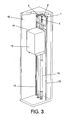
- the safety device for elevator apparatuses proposed by the invention comprises a crosshead (2), consisting of a support structure formed by two open-box UPN profiles, which is fixed to an upper area of two guides (12) of car (13), close to an upper end of an elevator shaft (16), as can be seen in Figure 3 .
- Said crosshead (2) is configured to support the safety device, which is turn configured to maintain a safety space between said upper end of the elevator shaft (16) and a roof (14) of a car (13) when the device is in an active position, which is the position depicted in Figures 2 and 3 .
- the crosshead (2) is fixed or attached to the guides (12) by means of two supports (1) with an L-shaped configuration, in collaboration with flanges and attachment means such as cylindrical bolts traversing the UPN profiles of the crosshead (2) and the head of the guide (12).
- the safety device comprises a rigid element (4) having a hinged end (4') which is in solidarity with the crosshead (2). Said hinged end (4') is likewise configured to rotate with respect to the crosshead (2).
- the device is configured to carry out said rotation of the hinged end (4') between an active position and an inactive position of the device.
- the rigid element (4) When the device is located in the active position, the rigid element (4) is in a substantially vertical position, whereas in the inactive position, the rigid element (4) is a substantially horizontal position, i.e., as has been depicted in Figure 1 .
- the rigid element (4) is in solidarity with the crosshead (2) by means of a frame (3) which is configured to be assembled with the possibility of positional adjustment on said crosshead (2), said frame (3) likewise being configured to support the hinged end (4') of the rigid element (4).
- the hinge of the hinged end (4') comprises a transverse shaft assembly which is formed by a shaft and two bushings attached to the frame (3), such that the rotation of the entire rigid element (4) is allowed.
- the frame (3) is formed by parts obtained from plates, on which all the functional components of the device are assembled, said frame (3) comprising, according to a preferred embodiment, a lower frame (3') consisting of supports with a C-shaped configuration which are located below the crosshead (2), such that the rigid element (4) is linked to said lower frame (3') by its hinged end (4').
- the device comprises magnetic means consisting of a permanent magnet, not depicted, located in the lower frame (3'), said means being configured to maintain the rigid element (4) in a substantially vertical position when the device is in an active position.
- the device likewise comprises magnetic means, consisting in an electromagnet (10), configured to maintain the rigid element (4) in a substantially horizontal position when the device is in an inactive position.
- the rigid element (4) is configured to be located in the active position, starting from the inactive position, only as a result of a gravitational action when said electromagnet (10) is not acting.
- the device comprises withdrawal means configured to automatically place the rigid element (4) in the inactive position, from the active position.
- said withdrawal means comprise driving means (9) configured to act on a drum (8) having a wound rope the end of which is attached to a free end (4") of the rigid element (4).
- the drum (8) is located on a lower face at an end of the frame (3) and is configured so that the rope securing the rigid element (4) at a free end (4") opposite the hinged end (4') is wound in said drum (8).
- the drum (8) comprises two side faces, in one of which there is housed a cylindrical stud bolt through which the rotational movement coming from the driving means (9) is transmitted.
- the driving means (9) consist of a synchronous geared motor which is assembled in the frame (3), externally in one of the side faces of the drum (8). Said driving means (9) are configured to generate a rotational movement to recover the rigid element (4) from the active position to the inactive position, in which it is horizontally placed, when its use has ended.
- the driving means (9) have a shaft which is housed in a shaft bushing which rotates in solidarity with the latter. On said bushing there is assembled a stud bolt which, upon interfering with the stud bolt located in the drum (8), will transmit the rotational movement to it.
- the electromagnet (10) is assembled in the frame (3), next to the drum (8), on the side face opposite the driving means (9). The actuation of the electromagnet determines the position of the drum (8).
- the electromagnet (10) can be assembled next to the driving means (9) and act on them, modifying their position with respect to the drum (8), which remains fixed in one position.
- the device likewise comprises a shaft bushing of the electromagnet (10) housing the shaft of the electromagnet (10) and inserted in the drum (8) or in the driving means (9), according to the configuration chosen.
- the device comprises a spring configured to work under compression and push the drum (8) or the driving means (9), according to the configuration chosen, when the power supply is interrupted, i.e., when the electromagnet (10) does not act. Likewise, the force driving the rigid element (4) from the inactive position to the active position is gravitational.
- the electric power feeds the electromagnet (10), which is maintained activated, whereby it pushes the drum (8) or the driving means (9), according to the configuration chosen, and makes the spring remain compressed.
- the stud bolt located in the shaft bushing of the driving means (9) retains the stud bolt located in the side of the drum (8), and makes the latter remain static with the rope wound and the rigid element (4) in the horizontal position.
- the electromagnet (10) stops acting and pushing the drum (8) or the driving means (9), according to the configuration chosen, whereby the spring is decompressed and the drum (8) and the driving means (9) move away from one another, whereby the stud bolts stop interfering and the drum (8) is freed, at this instant the rigid element (4) falls by gravity, rotating on the shaft assembly of the rigid element (4).
- the rigid element (4) When the rigid element (4) reaches the vertical position, it is suitably fixed under the actuation of the permanent magnet, located in the lower frame (3').
- the support in which said magnet is housed allows an adjustment ensuring the verticality of the rigid element (4).
- the device comprises means configured to detect the position of the rigid element (4), said means comprising two electric contacts (7) assembled in the lower frame (3') and configured to be actuated by means of two drives (5) in solidarity with the rigid element (4).
- the electric contacts (7) are operatively connected with an elevator apparatus maneuver control unit.
- the drives (5) of the electric contacts (7) consist of cams which are fixed at one end of the assembly of a transverse shaft of the rigid element (4), being offset 90° to one another to ensure the control of the inactive position and the active position.
- the drive of the electric contacts (7) sends a signal communicating the position of the rigid element (4) to the elevator apparatus maneuver control unit, all of this in collaboration with a corresponding electrical connection box (11).
- the offset placement of the drives (5) of the electric contacts (7) located at the ends of the shaft assembly of the rigid element (4) allows controlling the position of the device.
- the length of the rigid element (4) is calculated to ensure a sufficient safety required by the regulations.
- the rearming or repositioning of the device in its inactive position, starting from the active position, is carried out from a maneuver cabinet or control located on any of the floors, preferably in that corresponding to the upper level.
- the electric power drives the electromagnet (10) again, the latter acts on the drum (8) or on the driving means (9), according to the configuration chosen, compressing the spring and moving the stud bolts closer to one another so that they interfere with one another.
- the driving means (9) and the drum (8) thus rotate in a solidary manner again, and after overcoming the force exerted by the permanent magnet, the rope starts to be wound in the drum (8), dragging the rigid element (4) to is horizontal position.
- it is communicated to the maneuver control by means of the drive of one of the electric contacts (7), again activating the electromagnet (10) to maintain the device in its inactive position.
- the rigid element (4) comprises shock absorbing means (6), consisting of cellular polyurethane, located at its free end (4").
- the rigid element (4) has a telescopically adjustable length, which has not been depicted, which allows modifying the volume of the safety space.
- the safety device is configured to be actuated and located in the active position when any of the following situations occurs:
- a second aspect of the invention relates to an elevator apparatus comprising at least one safety device such as that described above.
- the device is applicable to any elevator configuration and type, either electrically driven, i.e., for elevator apparatuses comprising at least one drive sheave and at least one drive unit, or for hydraulically-driven elevator apparatuses, which comprise at least one hydraulic piston (15), as has been depicted in Figure 3 .
Landscapes
- Maintenance And Inspection Apparatuses For Elevators (AREA)
Applications Claiming Priority (1)
| Application Number | Priority Date | Filing Date | Title |
|---|---|---|---|
| ES200703447A ES2344621B1 (es) | 2007-12-26 | 2007-12-26 | Dispositivo de seguridad para aparatos elevadores y aparato elevador que comprende dicho dispositivo de seguridad. |
Publications (1)
| Publication Number | Publication Date |
|---|---|
| EP2075211A1 true EP2075211A1 (fr) | 2009-07-01 |
Family
ID=40430058
Family Applications (1)
| Application Number | Title | Priority Date | Filing Date |
|---|---|---|---|
| EP08380346A Withdrawn EP2075211A1 (fr) | 2007-12-26 | 2008-12-26 | Dispositif de sécurité pour appareils élévateurs, et appareil élévateur comportant ce dispositif de sécurité |
Country Status (2)
| Country | Link |
|---|---|
| EP (1) | EP2075211A1 (fr) |
| ES (1) | ES2344621B1 (fr) |
Cited By (3)
| Publication number | Priority date | Publication date | Assignee | Title |
|---|---|---|---|---|
| WO2015185766A1 (fr) * | 2014-06-04 | 2015-12-10 | Eliot Systems, S.L. | Système de sécurité pour opérations sur des éoliennes |
| CN108667256A (zh) * | 2018-05-09 | 2018-10-16 | 河南省城乡规划设计研究总院有限公司 | 一种随超高车辆速度开合的自供电电磁限高装置 |
| EP3401260A1 (fr) * | 2017-05-12 | 2018-11-14 | Otis Elevator Company | Systèmes d'édicule abritant un ascenseur |
Families Citing this family (1)
| Publication number | Priority date | Publication date | Assignee | Title |
|---|---|---|---|---|
| CN113226966B (zh) * | 2018-12-19 | 2023-03-14 | 因温特奥股份公司 | 用于提供临时的保护空间的装置 |
Citations (7)
| Publication number | Priority date | Publication date | Assignee | Title |
|---|---|---|---|---|
| NL9100059A (nl) * | 1991-01-11 | 1992-08-03 | Otis Liften B V | Beveiligingsinrichting voor een lift. |
| DE20119498U1 (de) * | 2001-11-30 | 2002-02-28 | Podelwitz Stahlbau Gmbh | Klappstütze für einen maschinenraumlosen Aufzug |
| DE10212267A1 (de) * | 2001-03-24 | 2002-09-26 | Wolfgang T Mueller | Temporärer Schutzraum insbesondere für Aufzüge |
| US6481534B1 (en) | 2001-08-27 | 2002-11-19 | Otis Elevator Company | Apparatus for maintaining adequate overhead space for car top mechanics in elevator systems |
| EP1314678A1 (fr) * | 2001-11-23 | 2003-05-28 | Inventio Ag | Dispositif de sécurité pour personnel de maintenance |
| WO2005026033A1 (fr) | 2003-09-15 | 2005-03-24 | Otis Elevator Company | Dispositifs de securite pour l'inspection d'un ascenseur |
| WO2006059174A1 (fr) * | 2004-11-30 | 2006-06-08 | Otis Elevator Company | Cabine d'ascenseur avec jambes a amortisseur de choc repliables, et ascenseur correspondant |
-
2007
- 2007-12-26 ES ES200703447A patent/ES2344621B1/es not_active Withdrawn - After Issue
-
2008
- 2008-12-26 EP EP08380346A patent/EP2075211A1/fr not_active Withdrawn
Patent Citations (7)
| Publication number | Priority date | Publication date | Assignee | Title |
|---|---|---|---|---|
| NL9100059A (nl) * | 1991-01-11 | 1992-08-03 | Otis Liften B V | Beveiligingsinrichting voor een lift. |
| DE10212267A1 (de) * | 2001-03-24 | 2002-09-26 | Wolfgang T Mueller | Temporärer Schutzraum insbesondere für Aufzüge |
| US6481534B1 (en) | 2001-08-27 | 2002-11-19 | Otis Elevator Company | Apparatus for maintaining adequate overhead space for car top mechanics in elevator systems |
| EP1314678A1 (fr) * | 2001-11-23 | 2003-05-28 | Inventio Ag | Dispositif de sécurité pour personnel de maintenance |
| DE20119498U1 (de) * | 2001-11-30 | 2002-02-28 | Podelwitz Stahlbau Gmbh | Klappstütze für einen maschinenraumlosen Aufzug |
| WO2005026033A1 (fr) | 2003-09-15 | 2005-03-24 | Otis Elevator Company | Dispositifs de securite pour l'inspection d'un ascenseur |
| WO2006059174A1 (fr) * | 2004-11-30 | 2006-06-08 | Otis Elevator Company | Cabine d'ascenseur avec jambes a amortisseur de choc repliables, et ascenseur correspondant |
Cited By (6)
| Publication number | Priority date | Publication date | Assignee | Title |
|---|---|---|---|---|
| WO2015185766A1 (fr) * | 2014-06-04 | 2015-12-10 | Eliot Systems, S.L. | Système de sécurité pour opérations sur des éoliennes |
| EP3401260A1 (fr) * | 2017-05-12 | 2018-11-14 | Otis Elevator Company | Systèmes d'édicule abritant un ascenseur |
| CN108861938A (zh) * | 2017-05-12 | 2018-11-23 | 奥的斯电梯公司 | 电梯超限运行系统 |
| CN108861938B (zh) * | 2017-05-12 | 2021-06-01 | 奥的斯电梯公司 | 电梯超限运行系统 |
| US11078043B2 (en) | 2017-05-12 | 2021-08-03 | Otis Elevator Company | Elevator overrun systems |
| CN108667256A (zh) * | 2018-05-09 | 2018-10-16 | 河南省城乡规划设计研究总院有限公司 | 一种随超高车辆速度开合的自供电电磁限高装置 |
Also Published As
| Publication number | Publication date |
|---|---|
| ES2344621A1 (es) | 2010-09-01 |
| ES2344621B1 (es) | 2011-06-24 |
Similar Documents
| Publication | Publication Date | Title |
|---|---|---|
| US8136637B2 (en) | Safety device for securing minimum spaces at the top or bottom of an elevator shaft being inspected, and elevator having such safety devices | |
| CN109476462B (zh) | 电梯装置 | |
| CN102216545B (zh) | 移动式悬臂平台及其安装方法 | |
| CN109476456B (zh) | 电梯装置和电梯 | |
| WO2018011461A1 (fr) | Système d'ascenseur à hauteur sous dalle réduite | |
| EP3257803B1 (fr) | Cabine d'ascenseur et système d'ascenseur | |
| CN109476460B (zh) | 用于安全维护工作的电梯装置 | |
| US20030168290A1 (en) | Elevator without machine room | |
| US9388018B2 (en) | Supply of rope to an elevator speed limiter | |
| EP2075211A1 (fr) | Dispositif de sécurité pour appareils élévateurs, et appareil élévateur comportant ce dispositif de sécurité | |
| JP5571130B2 (ja) | エレベータ装置 | |
| JP6272507B2 (ja) | エレベータ装置 | |
| KR101766914B1 (ko) | 엘리베이터용 수직 개폐식 도어의 상부 구동축 구동시스템 | |
| KR102018202B1 (ko) | 엘리베이터용 안전 착상 레벨 조정시스템 | |
| WO2016135922A1 (fr) | Dispositif d'ascenseur | |
| EP2488435B1 (fr) | Dispositif pour ménager des espaces dégagés dans une fosse d'ascenseur et en tête de cage pour l'exécution de travaux de maintenance dans des conditions de sécurité | |
| JP5572131B2 (ja) | エレベーター装置 | |
| KR20220125633A (ko) | 포설용 말비계탑승장치 | |
| GB2476704A (en) | An elevator safety system | |
| JP2013010604A (ja) | エレベータ装置 | |
| KR20120014631A (ko) | 엘리베이터용 양방향 조속기 | |
| EP3530605A1 (fr) | Système de garde-pieds de cabine d'ascenseur | |
| CN212531879U (zh) | 一种电梯定位及保护装置 | |
| EP1329411B1 (fr) | Ascenseur | |
| KR200389633Y1 (ko) | 추락방지장치가 구비된 엘리베이터용 승강카 |
Legal Events
| Date | Code | Title | Description |
|---|---|---|---|
| PUAI | Public reference made under article 153(3) epc to a published international application that has entered the european phase |
Free format text: ORIGINAL CODE: 0009012 |
|
| AK | Designated contracting states |
Kind code of ref document: A1 Designated state(s): AT BE BG CH CY CZ DE DK EE ES FI FR GB GR HR HU IE IS IT LI LT LU LV MC MT NL NO PL PT RO SE SI SK TR |
|
| AX | Request for extension of the european patent |
Extension state: AL BA MK RS |
|
| AKX | Designation fees paid | ||
| REG | Reference to a national code |
Ref country code: DE Ref legal event code: 8566 |
|
| STAA | Information on the status of an ep patent application or granted ep patent |
Free format text: STATUS: THE APPLICATION IS DEEMED TO BE WITHDRAWN |
|
| 18D | Application deemed to be withdrawn |
Effective date: 20100105 |