EP2075166B1 - Fußgängerschutzsystem in Autos - Google Patents
Fußgängerschutzsystem in Autos Download PDFInfo
- Publication number
- EP2075166B1 EP2075166B1 EP08380336A EP08380336A EP2075166B1 EP 2075166 B1 EP2075166 B1 EP 2075166B1 EP 08380336 A EP08380336 A EP 08380336A EP 08380336 A EP08380336 A EP 08380336A EP 2075166 B1 EP2075166 B1 EP 2075166B1
- Authority
- EP
- European Patent Office
- Prior art keywords
- hood
- vehicle
- bumper
- front bumper
- protection system
- Prior art date
- Legal status (The legal status is an assumption and is not a legal conclusion. Google has not performed a legal analysis and makes no representation as to the accuracy of the status listed.)
- Not-in-force
Links
Images

Classifications
-
- B—PERFORMING OPERATIONS; TRANSPORTING
- B60—VEHICLES IN GENERAL
- B60R—VEHICLES, VEHICLE FITTINGS, OR VEHICLE PARTS, NOT OTHERWISE PROVIDED FOR
- B60R21/00—Arrangements or fittings on vehicles for protecting or preventing injuries to occupants or pedestrians in case of accidents or other traffic risks
- B60R21/34—Protecting non-occupants of a vehicle, e.g. pedestrians
- B60R21/38—Protecting non-occupants of a vehicle, e.g. pedestrians using means for lifting bonnets
-
- B—PERFORMING OPERATIONS; TRANSPORTING
- B60—VEHICLES IN GENERAL
- B60R—VEHICLES, VEHICLE FITTINGS, OR VEHICLE PARTS, NOT OTHERWISE PROVIDED FOR
- B60R21/00—Arrangements or fittings on vehicles for protecting or preventing injuries to occupants or pedestrians in case of accidents or other traffic risks
- B60R21/34—Protecting non-occupants of a vehicle, e.g. pedestrians
-
- E—FIXED CONSTRUCTIONS
- E05—LOCKS; KEYS; WINDOW OR DOOR FITTINGS; SAFES
- E05B—LOCKS; ACCESSORIES THEREFOR; HANDCUFFS
- E05B77/00—Vehicle locks characterised by special functions or purposes
- E05B77/02—Vehicle locks characterised by special functions or purposes for accident situations
- E05B77/08—Arrangements for protection of pedestrians
-
- B—PERFORMING OPERATIONS; TRANSPORTING
- B60—VEHICLES IN GENERAL
- B60R—VEHICLES, VEHICLE FITTINGS, OR VEHICLE PARTS, NOT OTHERWISE PROVIDED FOR
- B60R19/00—Wheel guards; Radiator guards, e.g. grilles; Obstruction removers; Fittings damping bouncing force in collisions
- B60R19/02—Bumpers, i.e. impact receiving or absorbing members for protecting vehicles or fending off blows from other vehicles or objects
- B60R19/24—Arrangements for mounting bumpers on vehicles
- B60R19/38—Arrangements for mounting bumpers on vehicles adjustably or movably mounted, e.g. horizontally displaceable for securing a space between parked vehicles
- B60R19/40—Arrangements for mounting bumpers on vehicles adjustably or movably mounted, e.g. horizontally displaceable for securing a space between parked vehicles in the direction of an obstacle before a collision, or extending during driving of the vehicle, i.e. to increase the energy absorption capacity of the bumper
Definitions
- the present invention refers to a vehicle with a pedestrian protection system and specifically to a vehicle with a pedestrian protection system applied to the front part of the vehicle, which is the area where the pedestrian impacts in case of collision.
- the system of the invention is intended to reduce the effects on the pedestrian, in case of collision, produced by the impact against the front bumper and/or hood of the engine compartment.
- EP1795403 reffers to a pedestrian safety system in automobiles, wherein the vehicles have a front bumper and a hood which covers an engine compartment and wherein the front bumper and hood mounted can move along an X and Z direction, between positions of maximum and minimum separation with respect to rigid elements covered by said bumper and hood, this separation being inversely proportional to the speed of the vehicle.
- DE10037051 reffers to a safety device comprising an actuator operated by a sensor, which raises a bonnet and moves forward the bumper automatically, right after the raising of the bonnet.
- WO00/69707 relates to a front hood assembly hinged to the chassis of the motor vehicle via a multi-jointed hinge wherein the hinge comprises means for displacing a joint depending on the vehicle speed to an upper or a lower position.
- the present invention refers to a pedestrian protection system In automobiles which eliminates the aforementioned problems by offering a wider protection, covering possible impacts against the hood and the front bumper.
- the front bumper of the vehicle can be the first element against which the pedestrian impacts, at leg level, in case of collision. Behind the front bumper there are rigid components, such as the different radiators of the vehicle, chassis cross bars, etc., which produce serious injuries on the pedestrian's extremities at the moment of the impact.
- the system of the invention is based on producing a volume increase both between the hood and the rigid elements of the engine, as well as between the front bumper and the rigid elements behind it.
- the aforementioned volume increase is variable, and inversely proportional to the vehicle speed, that is to say, the higher the speed, the less volume increase, which enables to improve the aerodynamic conditions of the vehicle, while the lower the speed while circulating in urban areas where a collision with a pedestrian is more likely to happen, the higher the volume increase is, to offer more protection.
- the volume variation indicated is achieved by the movement of the hood and bumper of the vehicle along the X and Z direction, through simple constitution mechanism and performance.
- the system being claimed consists of a mechanism installed in the anchorage area of the engine hood and a mobile hinge.
- the mechanism comprises a mobile lock of the engine hood which can rotate on a shaft, thanks to an electric engine.
- the hinges of the engine hood have to be modified if the device is to be installed, since the engine hood will move both in the X direction and in the Z direction.
- the drive mechanism comprises modified hinges which enable the movement of the entire engine hood thanks to a track which enables the hinge to move along it, while keeping a correct opening at all times. Thanks to the aforementioned system two movements of the hood are achieved, namely rotation and translation, which have to be transmitted to the bumper. This transmission between the engine hood and the bumper is carried out through a mechanical joint between these two elements, through a joint or any other fixing system known. This joint enables all engine hood movements to be transmitted to the bumper, moving the two elements as if they were one.
- the system governed by the control unit corresponding to the security systems, can have three basic performance positions, according, in all cases, to the speed parameter register by the control unit, which will adapt the system to the security or aerodynamic conditions and which will be named as position 0, position 1 and position 2.
- Position 0 is the maximum security position. This position can be activated for speeds under 25 km/hour, which are typically used in urban areas, where top pedestrian protection is needed. In this position the assembly of the engine hood and bumper is in its most forward position, offering a considerable extra volume.
- Position 1 offers medium security. This position can be activated for speeds between 25 km/hour and 100 km/hour, allowing for good pedestrian protection in urban areas, without penalizing the driver's vision or the aerodynamic efficiency of the vehicle on fast lanes.
- the extra space between the mobile elements and the rigid elements is lightly inferior to position 0, but preserves the desired effectiveness of the system.
- the system of the invention enables to attain an important improvement with regard to pedestrian security, considerably reducing lower extremities injuries and keeping the correct protection in other areas, such as the head or torso.
- the main advantage of the proposed system with respect to the other existing systems is the simplicity of its use, eliminating expensive complex pyrotechnic systems, which are difficult to install. Additionally, it offers the advantage of having a system for aerodynamic improvement, which enables the optimization of the aerodynamic coefficient of the vehicle, thus slightly reducing consumption and, therefore, reducing medium emissions of gases which are harmful for the atmosphere.
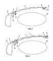
- Figures 1 to 3 show a longitudinal section of the hood 1, which shows the front compartment of the vehicle where the engine 15 is located.
- the hood 1 is mechanically connected to the front bumper 2 by any mechanical system generally indicated using the reference 3.
- the hood 1 is mounted using a modified hinge 4, to which a track 5 has been incorporated, along which said hinge can move in the X direction.
- the hood 1 is also related to a rotation mechanism 6, which is connected to the anchorage or lock 7 of said hood and which can be activated through an electric engine 8.
- the assembly of the hood 1 and the bumper 2 can move along the X and Z direccion, since the bumper 2 and the hood 1 being mechanically joined, both components move as if they were one.
- the rotation mechanism 6 can be directly connected to the electric engine 8 or, as it can be seen in figure 4 , it can be engaged with a rack 10 which is connected to the mechanism 6 through an intermediate arm 11 which is articulated according to the shaft 12 with the rack 10 and according to the shaft 13 with said mechanism 6.
- the intermediate transmission mechanism described with reference to figure 4 can be dispensed with, directly connecting the drive mechanism 6 to the electric engine 8 or using a simple gear assembly.
- a transmission mechanism like the one shown in figure 4 , which enables to place the electric engine 8 away from the drive mechanism 6.
- the assembly shown in figure 4 can have, for example, any of the three positions shown in figure 5 and indicated as a), b) and c), in which the hood 1 and front bumper 2 will be placed in the positions shown in figures 1, 2 and 3 , which are indicated as "position 0", "position 1" and "position 2".
- Position 1 shown in figure 2 , with the rotation mechanism 6 in position b) of figure 5 , will be a position of medium security. This position is activated, for example, for speeds ranging from 25 km/hour to 100 km/hour.
- the extra space between the mobile elements and the rigid elements is slightly smaller than in the case of "position 0", previously described with reference to figure 1 , but it maintains the desired effectiveness of the system.
- the assembly formed by the hood 1 and the bumper 2 is slightly retracted with respect to position 0, thus reducing part of the free space between the elements of engine 15 of the vehicle and the hood 1, but maintaining a good degree of protection, both for the pedestrian's head and his/her lower extremities and offering a good vision and a small aerodynamic improvement to the user of the vehicle.
- Figure 3 shows the hood 1 and bumper 2 in "position 2", which is the most aerodynamic one, with the rotation mechanism 6, in position c) of figure 5 .
- This position can be activated for speeds starting at 100 km/hour and it prioritizes the aerodynamic efficiency of the vehicle, at the expense of pedestrian security.
- the assembly of the hood 1 and the bumper 2 is entirely retracted in this position, favoring the aerodynamic profile of the vehicle and improving its features.
- hinge 4 is in the most retracted position of rack 5, considerably limiting the effectiveness of the system for pedestrian protection but slightly increasing the aerodynamic characteristics of the vehicle, which translates into an improved consumption and a reduction of pollutant emissions.
- Figures 2 and 3 show through a discontinuous line and with reference to numbers 1 and 2, the hood and front bumper condition in position 0 of figure 1 , where it is possible to see the movement of these components to "positions 2 and 3" and the variation in volume between them and the rigid elements of the engine 15 of the vehicle.
Landscapes
- Engineering & Computer Science (AREA)
- Mechanical Engineering (AREA)
- Superstructure Of Vehicle (AREA)
- Body Structure For Vehicles (AREA)
Claims (5)
- Fahrzeug mit einem Fußgängerschutzsystem, wobei das Fahrzeug eine Vorderstoßstange (2) und eine Motorhaube (1), die einen Motorraum (15) abdeckt, aufweist, und wobei die Vorderstoßstange (2) und die eingebaute Motorhaube (1) sich in einer X- und Z-Richtung zwischen Positionen einer maximalen und minimalen Trennung im Verhältnis zu unbiegsamen Elementen, die von der Stoßstange (2) und der Motorhaube (1) abgedeckt werden, bewegen können, wobei diese Trennung zur Geschwindigkeit des Fahrzeugs umgekehrt proportional ist, dadurch gekennzeichnet, dass die Bewegung der Motorhaube (1) und der Vorderstoßstange (2) von einem Antriebsmechanismus (6), der mit einer Verankerung (7) der Motorhaube (1) verbunden ist, und von einem beweglichen Gelenk für die Motorhaube (1) erzeugt wird, wobei die Vorderstoßstange (2) mit der Motorhaube derart verbunden ist, dass die Vorderstoßstange (2) von der Motorhaube (1) mitgenommen wird, wenn sich die Motorhaube (1) bewegt.
- Fahrzeug mit einem Fußgängerschutzsystem nach Anspruch 1, dadurch gekennzeichnet, dass der zuvor erwähnte Antriebsmechanismus (6) von einer Zentraleinheit, die Sicherheitsmitteln des Fahrzeugs entspricht, gemäß der Geschwindigkeit des Fahrzeugs geregelt wird, wobei die Trennung der Motorhaube (1) und der Stoßstange (2) in einem umgekehrten Verhältnis zur Geschwindigkeit des Fahrzeugs steht.
- Fahrzeug mit einem Fußgängerschutzsystem bei Kraftfahrzeugen nach Anspruch 2, dadurch gekennzeichnet, dass die Vorderstoßstange (2) und die Motorhaube (1) bewegt werden können, indem der Antriebsmechanismus (6) zwischen einer Endposition maximaler Trennung und Sicherheit für Geschwindigkeiten in Ballungsgebieten; einer Position minimaler Trennung und Sicherheit für Geschwindigkeiten auf Autobahnen und Schnellstraßen; und einer Zwischenposition von Trennung und Sicherheit für Geschwindigkeiten zwischen Fahrgeschwindigkeiten in Ballungsgebieten und Fahrgeschwindigkeiten auf Schnellstraßen aktiviert wird.
- Fahrzeug mit einem Fußgängerschutzsystem bei Kraftfahrzeugen nach Anspruch 3, dadurch gekennzeichnet, dass der Antriebsmechanismus (6) einen Elektromotor (8) umfasst, der mit den Verankerungselementen (7) der Motorhaube (1) über eine Übertragungsvorrichtung zusammenhängt, welche die direkte Bewegung der Vorderstoßstange (2) und der Motorhaube (1) in der Z-Richtung erzeugt.
- Fahrzeug mit einem Fußgängerschutzsystem bei Kraftfahrzeugen nach Anspruch 3, dadurch gekennzeichnet, dass das bewegliche Gelenk der Motorhaube (1) ein Scharnier (4) umfasst, das auf einer Schiene (5) eingebaut ist, an der es sich in der X- und Z-Richtung bewegen kann.
Applications Claiming Priority (1)
| Application Number | Priority Date | Filing Date | Title |
|---|---|---|---|
| ES200703469A ES2335460B1 (es) | 2007-12-28 | 2007-12-28 | Sistema de proteccion para peatones en vehiculos automoviles. |
Publications (3)
| Publication Number | Publication Date |
|---|---|
| EP2075166A2 EP2075166A2 (de) | 2009-07-01 |
| EP2075166A3 EP2075166A3 (de) | 2009-09-16 |
| EP2075166B1 true EP2075166B1 (de) | 2011-08-17 |
Family
ID=40379019
Family Applications (1)
| Application Number | Title | Priority Date | Filing Date |
|---|---|---|---|
| EP08380336A Not-in-force EP2075166B1 (de) | 2007-12-28 | 2008-12-12 | Fußgängerschutzsystem in Autos |
Country Status (2)
| Country | Link |
|---|---|
| EP (1) | EP2075166B1 (de) |
| ES (2) | ES2335460B1 (de) |
Family Cites Families (6)
| Publication number | Priority date | Publication date | Assignee | Title |
|---|---|---|---|---|
| DE3003568A1 (de) * | 1980-02-01 | 1981-08-06 | Daimler-Benz Ag, 7000 Stuttgart | Stossschutzvorrichtung fuer fahrzeuge, insbesondere kraftfahrzeuge |
| US6089628A (en) * | 1998-09-02 | 2000-07-18 | Ford Global Technologies, Inc. | Stiffener assembly for bumper system of motor vehicles |
| DE19922459C1 (de) * | 1999-05-17 | 2001-02-01 | Edscha Ag | Fronthaubenanordnung |
| DE10037051A1 (de) * | 2000-07-29 | 2002-02-28 | Acts Gmbh & Co Kg | Kraftfahrzeug und Stoßfängeranordnung für ein Kraftfahrzeug |
| US7192079B2 (en) * | 2004-03-26 | 2007-03-20 | Autoliv Asp, Inc. | Pedestrian protection apparatus for motor vehicles |
| US20070125589A1 (en) * | 2005-12-06 | 2007-06-07 | Murphy Morgan D | Situationally dependent vehicle structure for pedestrian protection |
-
2007
- 2007-12-28 ES ES200703469A patent/ES2335460B1/es not_active Expired - Fee Related
-
2008
- 2008-12-12 ES ES08380336T patent/ES2371585T3/es active Active
- 2008-12-12 EP EP08380336A patent/EP2075166B1/de not_active Not-in-force
Also Published As
| Publication number | Publication date |
|---|---|
| ES2335460A1 (es) | 2010-03-26 |
| ES2371585T3 (es) | 2012-01-05 |
| ES2335460B1 (es) | 2011-02-14 |
| EP2075166A2 (de) | 2009-07-01 |
| EP2075166A3 (de) | 2009-09-16 |
Similar Documents
| Publication | Publication Date | Title |
|---|---|---|
| US5785368A (en) | Vehicle with impact protection unit | |
| US8702152B1 (en) | Deployable front air dam | |
| US8260519B2 (en) | Retractable wheel covers | |
| US8177288B2 (en) | Motor vehicle | |
| MXPA01011776A (es) | Arreglo de cofre o capo frontal. | |
| EP0264425A4 (de) | Kombinierte vorwärts- und rückblickspiegeleinheit für kraftfahrzeuge. | |
| CN114502454A (zh) | 在汽车底板区域内的空气导向装置和具有这种空气导向装置的汽车 | |
| EP1745957B1 (de) | Türöffnungs- und -schliesssystem für Fahrzeuge | |
| EP2075166B1 (de) | Fußgängerschutzsystem in Autos | |
| KR102202841B1 (ko) | 문콕 예방 가능한 자동차문 | |
| WO2019206611A1 (en) | Digital mirror camera arm folding mechanism using gears | |
| CN100482503C (zh) | 雨刷装置 | |
| EP1842744B1 (de) | Kühlergrillblock und Fronthauben- Anordnung für eine Motorhaube | |
| KR20200039036A (ko) | 센서 적합형 액티브 범퍼 및 자율주행차량 | |
| JP4909780B2 (ja) | フロントスポイラー装置 | |
| EP2857290B1 (de) | Scharnieranordnung | |
| JP5013914B2 (ja) | 自動車のフード衝撃吸収構造 | |
| JP3115345U (ja) | 自動車用フェンダ一体型サイドミラー | |
| EP3689719B1 (de) | Aerodynamische vorrichtung für ein kraftfahrzeug | |
| WO2010070303A1 (en) | A safety arrangement | |
| US20080258489A1 (en) | Safety Device for a Motor Vehicle | |
| KR20060053612A (ko) | 자동차의 후드 컨트롤 시스템 | |
| JP2007203806A (ja) | 車両用衝突制御装置 | |
| KR102344508B1 (ko) | 차량용 사이드 카메라 시스템 | |
| KR0120036Y1 (ko) | 아웃사이드 미러의 동결 방지장치 |
Legal Events
| Date | Code | Title | Description |
|---|---|---|---|
| PUAI | Public reference made under article 153(3) epc to a published international application that has entered the european phase |
Free format text: ORIGINAL CODE: 0009012 |
|
| AK | Designated contracting states |
Kind code of ref document: A2 Designated state(s): AT BE BG CH CY CZ DE DK EE ES FI FR GB GR HR HU IE IS IT LI LT LU LV MC MT NL NO PL PT RO SE SI SK TR |
|
| AX | Request for extension of the european patent |
Extension state: AL BA MK RS |
|
| PUAL | Search report despatched |
Free format text: ORIGINAL CODE: 0009013 |
|
| AK | Designated contracting states |
Kind code of ref document: A3 Designated state(s): AT BE BG CH CY CZ DE DK EE ES FI FR GB GR HR HU IE IS IT LI LT LU LV MC MT NL NO PL PT RO SE SI SK TR |
|
| AX | Request for extension of the european patent |
Extension state: AL BA MK RS |
|
| 17P | Request for examination filed |
Effective date: 20100315 |
|
| AKX | Designation fees paid |
Designated state(s): DE ES FR GB IT |
|
| 17Q | First examination report despatched |
Effective date: 20100423 |
|
| GRAP | Despatch of communication of intention to grant a patent |
Free format text: ORIGINAL CODE: EPIDOSNIGR1 |
|
| GRAS | Grant fee paid |
Free format text: ORIGINAL CODE: EPIDOSNIGR3 |
|
| GRAA | (expected) grant |
Free format text: ORIGINAL CODE: 0009210 |
|
| AK | Designated contracting states |
Kind code of ref document: B1 Designated state(s): DE ES FR GB IT |
|
| REG | Reference to a national code |
Ref country code: GB Ref legal event code: FG4D |
|
| REG | Reference to a national code |
Ref country code: DE Ref legal event code: R096 Ref document number: 602008008926 Country of ref document: DE Effective date: 20111117 |
|
| REG | Reference to a national code |
Ref country code: ES Ref legal event code: FG2A Ref document number: 2371585 Country of ref document: ES Kind code of ref document: T3 Effective date: 20120105 |
|
| PGFP | Annual fee paid to national office [announced via postgrant information from national office to epo] |
Ref country code: ES Payment date: 20111227 Year of fee payment: 4 Ref country code: FR Payment date: 20120105 Year of fee payment: 4 |
|
| PGFP | Annual fee paid to national office [announced via postgrant information from national office to epo] |
Ref country code: DE Payment date: 20120111 Year of fee payment: 4 |
|
| PLBE | No opposition filed within time limit |
Free format text: ORIGINAL CODE: 0009261 |
|
| STAA | Information on the status of an ep patent application or granted ep patent |
Free format text: STATUS: NO OPPOSITION FILED WITHIN TIME LIMIT |
|
| 26N | No opposition filed |
Effective date: 20120521 |
|
| REG | Reference to a national code |
Ref country code: DE Ref legal event code: R097 Ref document number: 602008008926 Country of ref document: DE Effective date: 20120521 |
|
| GBPC | Gb: european patent ceased through non-payment of renewal fee |
Effective date: 20121212 |
|
| REG | Reference to a national code |
Ref country code: FR Ref legal event code: ST Effective date: 20130830 |
|
| REG | Reference to a national code |
Ref country code: DE Ref legal event code: R119 Ref document number: 602008008926 Country of ref document: DE Effective date: 20130702 |
|
| PG25 | Lapsed in a contracting state [announced via postgrant information from national office to epo] |
Ref country code: DE Free format text: LAPSE BECAUSE OF NON-PAYMENT OF DUE FEES Effective date: 20130702 |
|
| PG25 | Lapsed in a contracting state [announced via postgrant information from national office to epo] |
Ref country code: FR Free format text: LAPSE BECAUSE OF NON-PAYMENT OF DUE FEES Effective date: 20130102 Ref country code: GB Free format text: LAPSE BECAUSE OF NON-PAYMENT OF DUE FEES Effective date: 20121212 |
|
| PG25 | Lapsed in a contracting state [announced via postgrant information from national office to epo] |
Ref country code: IT Free format text: LAPSE BECAUSE OF NON-PAYMENT OF DUE FEES Effective date: 20121212 |
|
| REG | Reference to a national code |
Ref country code: ES Ref legal event code: FD2A Effective date: 20140306 |
|
| PG25 | Lapsed in a contracting state [announced via postgrant information from national office to epo] |
Ref country code: ES Free format text: LAPSE BECAUSE OF NON-PAYMENT OF DUE FEES Effective date: 20121213 |