EP2074699B1 - Mobilunterstützte abwärtsstreckenstrahlformung mit antennengewichtsrückkopplung - Google Patents
Mobilunterstützte abwärtsstreckenstrahlformung mit antennengewichtsrückkopplung Download PDFInfo
- Publication number
- EP2074699B1 EP2074699B1 EP07814467.2A EP07814467A EP2074699B1 EP 2074699 B1 EP2074699 B1 EP 2074699B1 EP 07814467 A EP07814467 A EP 07814467A EP 2074699 B1 EP2074699 B1 EP 2074699B1
- Authority
- EP
- European Patent Office
- Prior art keywords
- downlink
- antenna
- bsant
- downlink transmit
- receiver
- Prior art date
- Legal status (The legal status is an assumption and is not a legal conclusion. Google has not performed a legal analysis and makes no representation as to the accuracy of the status listed.)
- Not-in-force
Links
Images



Classifications
-
- H—ELECTRICITY
- H04—ELECTRIC COMMUNICATION TECHNIQUE
- H04B—TRANSMISSION
- H04B1/00—Details of transmission systems, not covered by a single one of groups H04B3/00 - H04B13/00; Details of transmission systems not characterised by the medium used for transmission
- H04B1/06—Receivers
-
- H—ELECTRICITY
- H01—ELECTRIC ELEMENTS
- H01Q—ANTENNAS, i.e. RADIO AERIALS
- H01Q3/00—Arrangements for changing or varying the orientation or the shape of the directional pattern of the waves radiated from an antenna or antenna system
- H01Q3/26—Arrangements for changing or varying the orientation or the shape of the directional pattern of the waves radiated from an antenna or antenna system varying the relative phase or relative amplitude of energisation between two or more active radiating elements; varying the distribution of energy across a radiating aperture
- H01Q3/30—Arrangements for changing or varying the orientation or the shape of the directional pattern of the waves radiated from an antenna or antenna system varying the relative phase or relative amplitude of energisation between two or more active radiating elements; varying the distribution of energy across a radiating aperture varying the relative phase between the radiating elements of an array
-
- H—ELECTRICITY
- H01—ELECTRIC ELEMENTS
- H01Q—ANTENNAS, i.e. RADIO AERIALS
- H01Q3/00—Arrangements for changing or varying the orientation or the shape of the directional pattern of the waves radiated from an antenna or antenna system
- H01Q3/26—Arrangements for changing or varying the orientation or the shape of the directional pattern of the waves radiated from an antenna or antenna system varying the relative phase or relative amplitude of energisation between two or more active radiating elements; varying the distribution of energy across a radiating aperture
- H01Q3/2605—Array of radiating elements provided with a feedback control over the element weights, e.g. adaptive arrays
-
- H—ELECTRICITY
- H04—ELECTRIC COMMUNICATION TECHNIQUE
- H04B—TRANSMISSION
- H04B7/00—Radio transmission systems, i.e. using radiation field
- H04B7/02—Diversity systems; Multi-antenna system, i.e. transmission or reception using multiple antennas
- H04B7/04—Diversity systems; Multi-antenna system, i.e. transmission or reception using multiple antennas using two or more spaced independent antennas
- H04B7/06—Diversity systems; Multi-antenna system, i.e. transmission or reception using multiple antennas using two or more spaced independent antennas at the transmitting station
- H04B7/0613—Diversity systems; Multi-antenna system, i.e. transmission or reception using multiple antennas using two or more spaced independent antennas at the transmitting station using simultaneous transmission
- H04B7/0615—Diversity systems; Multi-antenna system, i.e. transmission or reception using multiple antennas using two or more spaced independent antennas at the transmitting station using simultaneous transmission of weighted versions of same signal
- H04B7/0619—Diversity systems; Multi-antenna system, i.e. transmission or reception using multiple antennas using two or more spaced independent antennas at the transmitting station using simultaneous transmission of weighted versions of same signal using feedback from receiving side
- H04B7/0621—Feedback content
- H04B7/0634—Antenna weights or vector/matrix coefficients
-
- H—ELECTRICITY
- H04—ELECTRIC COMMUNICATION TECHNIQUE
- H04L—TRANSMISSION OF DIGITAL INFORMATION, e.g. TELEGRAPHIC COMMUNICATION
- H04L25/00—Baseband systems
- H04L25/02—Details ; arrangements for supplying electrical power along data transmission lines
- H04L25/0202—Channel estimation
- H04L25/0204—Channel estimation of multiple channels
-
- H—ELECTRICITY
- H04—ELECTRIC COMMUNICATION TECHNIQUE
- H04L—TRANSMISSION OF DIGITAL INFORMATION, e.g. TELEGRAPHIC COMMUNICATION
- H04L25/00—Baseband systems
- H04L25/02—Details ; arrangements for supplying electrical power along data transmission lines
- H04L25/0202—Channel estimation
- H04L25/0224—Channel estimation using sounding signals
- H04L25/0228—Channel estimation using sounding signals with direct estimation from sounding signals
-
- H—ELECTRICITY
- H04—ELECTRIC COMMUNICATION TECHNIQUE
- H04L—TRANSMISSION OF DIGITAL INFORMATION, e.g. TELEGRAPHIC COMMUNICATION
- H04L25/00—Baseband systems
- H04L25/02—Details ; arrangements for supplying electrical power along data transmission lines
- H04L25/03—Shaping networks in transmitter or receiver, e.g. adaptive shaping networks
- H04L25/03006—Arrangements for removing intersymbol interference
- H04L25/03343—Arrangements at the transmitter end
-
- H—ELECTRICITY
- H04—ELECTRIC COMMUNICATION TECHNIQUE
- H04L—TRANSMISSION OF DIGITAL INFORMATION, e.g. TELEGRAPHIC COMMUNICATION
- H04L5/00—Arrangements affording multiple use of the transmission path
- H04L5/14—Two-way operation using the same type of signal, i.e. duplex
-
- H—ELECTRICITY
- H04—ELECTRIC COMMUNICATION TECHNIQUE
- H04W—WIRELESS COMMUNICATION NETWORKS
- H04W16/00—Network planning, e.g. coverage or traffic planning tools; Network deployment, e.g. resource partitioning or cells structures
- H04W16/24—Cell structures
- H04W16/28—Cell structures using beam steering
-
- H—ELECTRICITY
- H04—ELECTRIC COMMUNICATION TECHNIQUE
- H04B—TRANSMISSION
- H04B7/00—Radio transmission systems, i.e. using radiation field
- H04B7/02—Diversity systems; Multi-antenna system, i.e. transmission or reception using multiple antennas
- H04B7/04—Diversity systems; Multi-antenna system, i.e. transmission or reception using multiple antennas using two or more spaced independent antennas
- H04B7/06—Diversity systems; Multi-antenna system, i.e. transmission or reception using multiple antennas using two or more spaced independent antennas at the transmitting station
- H04B7/0613—Diversity systems; Multi-antenna system, i.e. transmission or reception using multiple antennas using two or more spaced independent antennas at the transmitting station using simultaneous transmission
- H04B7/0615—Diversity systems; Multi-antenna system, i.e. transmission or reception using multiple antennas using two or more spaced independent antennas at the transmitting station using simultaneous transmission of weighted versions of same signal
- H04B7/0619—Diversity systems; Multi-antenna system, i.e. transmission or reception using multiple antennas using two or more spaced independent antennas at the transmitting station using simultaneous transmission of weighted versions of same signal using feedback from receiving side
- H04B7/0636—Feedback format
-
- H—ELECTRICITY
- H04—ELECTRIC COMMUNICATION TECHNIQUE
- H04L—TRANSMISSION OF DIGITAL INFORMATION, e.g. TELEGRAPHIC COMMUNICATION
- H04L25/00—Baseband systems
- H04L25/02—Details ; arrangements for supplying electrical power along data transmission lines
- H04L25/03—Shaping networks in transmitter or receiver, e.g. adaptive shaping networks
- H04L25/03006—Arrangements for removing intersymbol interference
- H04L2025/0335—Arrangements for removing intersymbol interference characterised by the type of transmission
- H04L2025/03426—Arrangements for removing intersymbol interference characterised by the type of transmission transmission using multiple-input and multiple-output channels
Definitions
- This invention relates in general to wireless communication, and more specifically, to downlink beamforming from base stations to mobile devices with multiple receiver antennas.
- Communications systems are generally defined in terms of their communications parameters (e.g. data rate, channel bandwidth, modulation type etc.).
- the communications parameters of communications systems are chosen according to the characteristics of the communications channel and the type of communications required.
- the propagation of signals between communicating units are affected by the rapidly varying multipath and fading characteristics of the communications channel. Consequently the communications parameters for such mobile communications systems are chosen to take into account the variations in the gain and delay characteristics of the channel due to multipath and fading effects.
- the communications parameters of a communications system are fixed. However, to maximize system performance in a mobile communications system, it is advantageous to continuously optimize the communications parameters of the communications system according to the current state of the rapidly varying communications channel.
- the mobile unit transmits a known tone or sequence in an uplink to a Base Station (BS).
- BSs are medium to high-power multi-channel two-way radios which are in a fixed location and serve as access points between mobile devices and the rest of a communication system.
- the base station then processes the information and transmits in a downlink the desired communications parameters to the mobile unit for use in future communications between the two communicating units.
- the downlink (DL) RF channel is similar to the uplink (UL) RF channel, and thus can be derived at the BS using an uplink sounding signal.
- Beamforming is a signal processing technique used with an array of antennas, where the directionality of a radiation pattern is controlled by adjusting the phase of the coordinated antennas.
- beamforming can be used to increase the gain in the direction the signal is to be sent by adjusting the phase of each antenna to create peaks and nulls in the radiation pattern.
- An example of a mobile unit communicating with BSs is a mobile unit with two receive antennas, but only one transmit antenna.
- the DL channel information is used to properly perform the downlink beamforming of the base station antennas.
- UL sounding signals from the single transmit antenna of the mobile unit do not provide the DL channel information from the BS antennas to the non-transmitting but receiving-only antenna(s) of the mobile unit.
- the estimated UL channel information from the UL sounding signal differs from the DL channel since the UL and DL are on different carrier frequency.
- US 2004/178954 A1 discloses a method and apparatus for multi-antenna transmission in a multiple-input, multiple-output communication system where a reduced number of transmit weight matrices are fed back to the transmitter.
- US 2006/094435 A1 discloses a method for communicating channel estimates on a plurality of subcarriers between a transmitting device and a receiving device where the transmitting device determines a channel estimates on a plurality of subcarriers and then encodes the channel estimates into at least one encoded channel waveform.
- the invention provides a method on an RF communications receiver, as claimed in claim 1.
- the invention provides a method on an RF communications receiver, as claimed in claim 3.
- Embodiments of the present invention provide a system for downlink beamforming in a FDD wireless communication network and in a TDD wireless communication network having mobile transmitter/receiver devices, referred to herein as "subscriber units" (SUs), with normally a greater number of receive antennas than transmit antennas.
- the SU determines downlink beamforming weights to be applied to the transmit antennas of a "base station" (BS) based on the previous downlink transmission for downlink antenna specific pilot symbols.
- the downlink beamforming weights in one example, are complex numbers, which are applied to transmitted downlink signals to form a transmit pattern adapted to propagation channels between each transmit antenna of the base station and each receive antenna of the mobile SU.
- the SU communicates the determined beamforming weights using the uplink sounding channel.
- the BS combines the received signal on sounding symbol subcarriers to determine the BS weights for each antenna and then forms the corresponding beams for each SU receiver antenna based on weights received from the SU on the uplink sounding channel.
- FIG. 1 shows a block diagram of a communications system 100.
- a first communications unit 102 is a BS and a second communications unit 104 is a SU.
- the BS 102 includes both a transmitter 106 and a receiver 108 operably coupled to an array of four antennas BSAnt-0, BSAnt-1, BSAnt-2, and BSAnt-3, for communicating to the SU 104.
- the coupling of the transmitter 106 and receiver 108 to the array of four antennas BSAnt-0, BSAnt-1, BSAnt-2, and BSAnt-3 is accomplished through a weighting unit 150.
- the interconnections of the weighting unit 150 are shown in FIG. 6 .
- weighting unit 150 includes a set of transmit weighting multipliers T x w 0 , T x w 1 , T x w 2 , and T x w 3 and a set of receive weighting multipliers R x w 0 , R x w 1 , R x w 2 , and R x w 3 .
- a separate one of the weighting multipliers T x w 0 , T x w 1 , T x w 2 , and T x w 3 is coupled between the transmitter 106 and each of the BS antennas, BSAnt-0 602, BSAnt-1 604, BSAnt-2 606, and BSAnt-3 608, respectively.
- Each multiplier, T x w 0 , T x w 1 , T x w 2 , and T x w 3 multiplies the transmit signal by a specified complex weight w 0 , w 1 , w 2 , and w 3 , respectively.
- a set of receive weighting multipliers R x w 0 , R x w 1 , R x w 2 , and R x w 3 are coupled between the receiver 108 and each of the BS antennas, BSAnt-0 602, BSAnt-1 604, BSAnt-2 606, and BSAnt-3 608, respectively.
- Each multiplier, R x w 0 , R x w 1 , R x w 2 , and R x w 3 multiplies the receive signal by a specified weight w 0 , w 1 , w 2 , and w 3 , respectively.
- the BS 102 is controlled by a controller 118.
- the controller 118 is the brains behind the BS 102 and handles allocation of radio channels, receives measurements from the SUs, sets beamforming weight for the transmit and receive antennas and controls handovers from BS to BS. Additionally, databases for the sites, including information such as carrier frequencies, frequency hopping lists, power reduction levels, receiving levels for cell border calculation, are stored in, or communicatively coupled to, the controller 118.
- the SU 104 includes a receiver 114 operably coupled to two receive antennas SUAnt-0 160 and SUAnt-1 162 and also includes a transmitter 112 operably coupled to SUAnt-0 160, which is both a transmit and receive antenna. Therefore, there are 4 transmitting antennas at the BS 102 and 2 receive antennas at SU 104. In this example, there are eight BS to SU downlink propagation channels-a channel from each BS transmit antenna to each SU receive antenna.
- the SU 104 operates under the control of a device controller/processor 120, that controls the sending and receiving of wireless communication signals.
- the device controller 120 electrically couples the antennas SUAnt-0 160 and SUAnt-1 162 through a transmit/receive signal combiner 122 to the receiver 114.
- the receiver 114 decodes the received signals and provides those decoded signals to the device controller 120.
- the device controller 120 In transmit mode, the device controller 120 electrically couples the transmitter 112 to the antenna SUAnt-0 160 through the transmit/receive signal combiner 122.
- the device controller 120 operates the transmitter 112 and receiver 114 according to instructions stored in a memory 124.
- the SU 104 in one embodiment, is capable of wirelessly communicating data using the IEEE 802.16e standard, 3GPP/3GPP2 standards, or any other communication scheme that supports Time Division Duplex (TDD) or Frequency Division Duplex (FDD).
- TDD Time Division Duplex
- FDD Frequency Division Duplex
- the uplink (UL) and downlink (DL) channels are symmetric after BS antenna calibration.
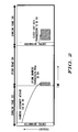
- FIG. 2 shows a timing diagram for a TDD Frequency Division Multiple Access (FDMA) scheme.
- FDMA Frequency Division Multiple Access
- the RF propagation channel between each transmitting BS antenna and each MS antenna for a subcarrier k is denoted as show in Table A. TABLE A.
- BS Ant-0 BS ant-1 BS ant-2 BS ant-3 MS ant-0 H00[k] H10[k] H20[k] H30[k] MS ant-1 H01[k] H11[k] H21[k] H31[k] where H is the RF propagation channel.
- the process flow diagram of FIG. 3 shows a first embodiment of the present invention.
- the process starts at step 300 and moves directly to step 302, where the BS 102 transmits a data signal to the SU 104 which, in turn, receives the data signal in step 304.
- the BS 102 Prior to the SU 104 responding by transmitting a data signal back to the BS 102, the BS 102 transmits a Common Pilot Signal (CPS) containing a pilot signal in step 306.
- the common pilot signal (CPS) sent by the BS 102 contains subcarrier frequencies and is transmitted by each BS 102 transmit antenna, as described below.
- FIG. 2 shows the relationship between DL, UL, UL sounding, and related DL data transmission.
- the DL control channel in the first frame 202 allocates UL sounding carriers for SU 104.
- the SU 104 transmits an UL sounding signal on the allocated subcarriers in the following UL frame 204.
- the BS forms a DL beam based on the received UL sounding signal.
- a DL common pilot i.e., DL pilot signal with no weight (beamforming) on the pilot signal.
- the SU calculates BS antenna weights based on DL common pilots from every BS antenna.
- the SU transmits an UL sounding signal, which carries the antenna weights calculated above.
- the BS then forms the DL beam to transmit DL data using the antenna weights communicated through the UL sounding signal.
- UL sounding signals there is no information carried on the sounding signal. That is, the UL sounding signal in conventional systems is similar to a reference signal. where the superscript H represents the conjugate of a complex number.
- a subset of the UL subcarriers is transmitted from each mobile transmit antenna.
- Subcarrier i is on transmit antenna 0
- subcarrier i + D is on transmit antenna 1
- subcarrier i + 2D is on transmit antenna 2, etc.
- the Decimation factor is the number of subcarriers between adjacent sounding subcarriers allocated to this mobile.
- the SU 104 receives the DL common pilot signal (CPS) in step 308 after a short period, due to channel propagation and system delays, and processes the common pilot.
- the SU 104 estimates channel parameters in a known way, and calculates downlink beamforming weights w 0 for BSAnt-0, w 1 for BSAnt-1, w 2 for BSAnt-2, and w 3 for BSAnt-3 in step 310 that are to be applied to the BS antennas.
- the SU 104 transmits, in step 312, S(i) on subcarrier i, S(i+D) on subcarrier i+D, S(i+2D) on subcarrier i+2D, and S(i+3D) on subcarrier i+3D as defined above, after modulating the product of the complex value corresponding to the antenna weights, as calculated at step 310, and the conjugate of the sum of complex values corresponding to the responses of the channels responses.
- the modulating in one embodiment includes modulating a respective modulation signal onto each uplink subcarrier within n uplink subcarriers, wherein each respective modulation signal comprises a respective complex value corresponding to one respective downlink transmit antenna weighting factor within the n downlink transmit antenna weighting factors.
- the modulation of the subcarriers is able to be represented as modulating a respective signal on a first subcarrier within the n uplink subcarriers with a first antenna weight corresponding to at least one respective downlink data stream from the remote transmitter to the receiver; and modulating an m th of the n subcarriers with a complex value corresponding to an m th antenna weight corresponding to the at least one respective downlink data stream from the remote transmitter to the receiver, where each uplink subcarrier is separated from each other uplink subcarrier by a decimation factor, wherein 1 ⁇ m ⁇ n.
- the modulation of some embodiments of the present invention is further described as summing, to produce a first sum, complex values corresponding to the respective RF propagation channel for the first subcarrier between n base station transmit antennas and a receive antenna within the at least one receive antennas that is capable of transmitting; calculating a conjugate of the first sum; multiplying the first downlink antenna weight by the conjugate of the first sum to produce the respective modulation signal; and scaling the respective modulation signal for the first subcarrier.
- Some embodiments quantize the complex value corresponding to the antenna weights prior to multiplying the antenna weight by the conjugate of the sum of the channel responses. This transmission is simultaneous in time, and only from the SU antenna SUAnt-0 160.
- scaling can be added on S(i), S(i+D), S(i+2D) and S(i+3D) to reduce the peak to average power ratio of the transmit signal.
- the BS 102 receives signals at each of the receive antennas, which are shown in Table 2 below. TABLE 2.
- R0 is the received signal on BS ant-0
- R1 is the received signal on BS ant-1
- R2 is the received signal on BS ant-2
- R3 is the received signal on BS ant-3
- phase w k Atan ⁇ Im ⁇ r ⁇ i + k ⁇ D Re ⁇ r ⁇ i + k ⁇ D
- Atan() is the Arctangent function
- Im() is the imaginary part of a complex number
- Re() is the real part of a complex number
- the derived phase values are then, in step 330, used at the BS 102 in "equal gain beamforming", i.e., the amplitude of the beamforming weights are constant and the phase of the beamforming weights are from the formula above, to transmit data to the SU 104 by utilizing the derived weight w k for each of the transmit antennas BSAnt-0 through BSAnt-3.
- the process ends at step 332.
- the SU 104 once again estimates channel parameters, and calculates the downlink beamforming weights w 0 for BS ant-0, w 1 for BS ant-1, w 2 for BS ant-2, and w 3 for BS ant-3, just as was done in step 302 of FIG. 3 .
- the SU 104 transmits an UL signal that contains 16 sounding symbol subcarriers.
- These subcarriers are received and processed by the BS antennas in groups of four.
- BS antenna 0 receives subcarrier i, i + D, i + 2D, and i + 3D
- BS antenna 1 receives subcarriers i + 4D, i + 5D, i + 6D, and i + 7D, and so forth.
- step 410 the received signal on BSAnt-0 at subcarrier i+kD, the received signal on BSAnt-1 at subcarrier i+(4+k)D, the received signal on BSAnt-2 at subcarrier i+(8+k)D, and the received signal on BSAnt-3 at subcarrier i+(12+k)D are similarly combined to form the received signal r k .
- r k w k ⁇ H 00 ⁇ i + k ⁇ D 2 + H 10 ⁇ i + 4 + k ⁇ D 2 + H 20 ⁇ i + 8 + k ⁇ D 2 + H 30 ⁇ i + 12 + k ⁇ D 2
- phase of w k is detected from r k in step 412.
- Phase w k Atan Im r k Re r k
- Atan() is the Arctangent function
- Im() is the imaginary part of a complex number
- Re() is the real part of a complex number.
- the SU 104 once again estimates channel parameters, and calculates the downlink beamforming weights w 0 for BS ant-0, w 1 for BS ant-1, w 2 for BS ant-2, and w 3 for BS ant-3, just as was done in step 302 of FIG. 3 .
- the SU transmit the antenna weights on the UL sounding subcarriers.
- Sub - carrier i S i w 0 ⁇
- Sub - carrier i + D S ⁇ i + D w 1 ⁇
- Sub - carrier i + 2 ⁇ D S ⁇ i + 2 ⁇ D w 2 ⁇
- Sub - carrier i + 3 ⁇ D S ⁇ i + 3 ⁇ D w 3 w k Beamforming weight for BS antenna - k D Decimation factor
- ⁇ 00 ( i + kD ) is the estimated UL channel from MSAnt-0 to BSAnt-0 at subcarrier i+kD
- ⁇ 10 ( i + kD ) is the estimated UL channel from MSAnt-0 to BSAnt-1 at subcarrier i+kD
- ⁇ 20 ( i + kD ) is the estimated UL channel from MSAnt-0 to BSAnt-2 at subcarrier i+kD
- ⁇ 30 ( i + kD ) is the estimated UL channel from MSAnt-0 to BSAnt-3 at subcarrier i+kD.
- the derived weighting factors are then, in step 330, used at the BS 102 in downlink beamforming to transmit data to the SU 104 by utilizing the derived weight ⁇ k for each of the transmit antennas BSAnt-0 through BSAnt-3.
- the process ends at step 332.
- the three embodiments are for single data stream transmission, i.e., there is single data stream beamformed from one BS to one mobile.
- a similar approach can be extended to multiple data streams.
- Each data stream has a different set of beamforming weights.
- the SU 104 in this case calculates these sets of beamforming weights and feeds back the weights to the BS.
- FIG. 5 is a block diagram illustrating a detailed view of a BS controller 500, such as the BS controller 118 of FIG. 1 , according to an embodiment of the present invention.
- the BS controller 500 in one embodiment, resides within the BS 102. In other embodiments, the BS controller 500 resides outside of and is communicatively coupled to the BS 102.
- the BS controller 500 includes a processor 504 that is communicatively connected to a main memory 506 (e.g., volatile memory), a non-volatile memory 512, and a network adapter hardware 516 that is used to provide an interface to the network 100.
- the BS processor 504 acts as a weight extraction processor and extracts, by demodulating signals on the uplink subcarriers, a plurality of downlink transmission antenna weights comprising each of the respective complex values modulated onto each respective uplink subcarrier.
- the BS 500 also includes a man-machine interface ("MMI") 514.
- MMI man-machine interface
- the MMI 514 in one embodiment, is used to directly connect one or more diagnostic devices 528 to the BS controller 500.
- a system bus 518 interconnects these system components.
- the BS controller 500 is coupled to a sounding transmitter 502 to control the transmission of sounding signals to the remote SU devices, as described above.
- the BS controller 500 is also coupled to a Tx/Rx weighting unit 150 and controls the transmit (Tx) antenna weights and the receiver (Rx) antenna weights that are applied to each transmit and receive antenna, as is described above.
Landscapes
- Engineering & Computer Science (AREA)
- Signal Processing (AREA)
- Computer Networks & Wireless Communication (AREA)
- Power Engineering (AREA)
- Physics & Mathematics (AREA)
- Mathematical Physics (AREA)
- Mobile Radio Communication Systems (AREA)
- Radio Transmission System (AREA)
- Time-Division Multiplex Systems (AREA)
Claims (3)
- Verfahren an einem RF-Kommunikationsempfänger, wobei das Verfahren umfasst:Empfangen von n Downlink-Pilotsignalen mit mindestens einer Empfangsantenne (SUAnt-0, SUAnt-1) an einem Empfänger, wobei jedes der n Downlink-Pilotsignale einer betreffenden von n Downlink-Sendeantennen (BSAnt-0, BS Ant-1, BSAnt-2, BSAnt-3) an einem die n Downlink-Pilotsignale sendenden entfernten Sender zugeordnet wird;Bestimmen eines jeweiligen RF-Übertragungskanals zwischen jeder betreffenden Empfangsantenne innerhalb der mindestens einen Empfangsantenne an dem Empfänger und jeder betreffenden Downlink-Sendeantenne innerhalb der n Downlink-Sendeantennen an dem entfernten Sender auf der Basis der empfangenen n Downlink-Pilotsignale; undBestimmen von n Downlink-Sendeantennen-Gewichtungsfaktoren für jeden Downlink-Datenstrom von dem entfernten Sender zu dem Empfänger auf der Basis von Charakteristiken jedes betreffenden Downlink-RF-Übertragungskanals, wobei jeder Downlink-Sendeantennen-Gewichtungsfaktor innerhalb der n Downlink-Sendeantennen-Gewichtungsfaktoren einem jeweiligen Gewichtungsfaktor entspricht, der bei einer betreffenden Downlink-Sendeantenne innerhalb von n Downlink-Sendeantennen und einem betreffenden, von dem entfernten Sender zu dem Empfänger übertragenen Downlink-Datenstrom innerhalb mindestens eines Downlink-Datenstroms anzuwenden ist, gekennzeichnet durch:Modulieren eines betreffenden Modulationssignals auf einen ersten von n Uplink-Unterträgern durch
Summieren von komplexen Werten entsprechend dem jeweiligen RF-Übertragungskanal für einen ersten Unterträger zwischen n Basisstation-Sendeantennen und der mindestens einen Sende-Empfangsantenne an dem entfernten Sender, zum Bilden einer ersten Summe;
das Berechnen einer konjugierten Zahl der ersten Summe;
das Multiplizieren eines ersten der n Downlink-Antennen-Gewichtungsfaktoren mit der konjugierten Zahl der ersten Summe, um das betreffende Modulationssignal zu erzeugen; und
das Senden der ersten Uplink-Unterträger durch mindestens eine Sende-Empfangsantenne innerhalb der mindestens einen Empfangsantenne. - Verfahren nach Anspruch 1, wobei das Verfahren nach dem Berechnen einer konjugierten Zahl der ersten Summe Quantisieren der ersten Downlink-Antennengewichtung umfasst.
- Verfahren an einem RF-Kommunikationsempfänger, wobei das Verfahren umfasst:Empfangen von n Downlink-Pilotsignalen mit mindestens einer Empfangsantenne (SUAnt-0, SUAnt-1) an einem Empfänger, wobei jedes der n Downlink-Pilotsignale einer betreffenden von n Downlink-Sendeantennen (BSAnt-0, BS Ant-1, BSAnt-2, BSAnt-3) an einem die n Downlink-Pilotsignale sendenden entfernten Sender zugeordnet wird;Bestimmen eines jeweiligen RF-Übertragungskanals zwischen jeder betreffenden Empfangsantenne innerhalb der mindestens einen Empfangsantenne an dem Empfänger und jeder betreffenden Downlink-Sendeantenne innerhalb der n Downlink-Sendeantennen an dem entfernten Sender auf der Basis der empfangenen n Downlink-Pilotsignale; undBestimmen von n Downlink-Sendeantennen-Gewichtungsfaktoren für jeden Downlink-Datenstrom von dem entfernten Sender zu dem Empfänger auf der Basis von Charakteristiken jedes betreffenden Downlink-RF-Übertragungskanals, wobei jeder Downlink-Sendeantennen-Gewichtungsfaktor innerhalb der n Downlink-Sendeantennen-Gewichtungsfaktoren einem jeweiligen Gewichtungsfaktor entspricht, der bei einer betreffenden Downlink-Sendeantenne innerhalb von n Downlink-Sendeantennen und einem betreffenden, von dem entfernten Sender zu dem Empfänger übertragenen Downlink-Datenstrom innerhalb mindestens eines Downlink-Datenstroms anzuwenden ist, gekennzeichnet durch:Modulieren eines betreffenden Modulationssignals auf jeden Uplink-Unterträger durch
Identifizieren von n Gruppen von Gewichtungsprodukten, wobei jede der n Gruppen von Gewichtungsprodukten jeweilige n Gewichtungsprodukte enthält und wobei jede Gruppe von Gewichtungsprodukten innerhalb der n Gruppen von Gewichtungsprodukten durch eine betreffende Downlink-Sendeantenne innerhalb der n Downlink-Sendeantennen an dem entfernten Sender zu empfangen ist;
Zuordnen jedes Gewichtungsprodukts der n*n Gewichtungsprodukte zu einem betreffenden Unterträger,
Zuordnen jedes der n Gewichtungsprodukte innerhalb jeder der n Gruppen von Gewichtungsprodukten zu einem betreffenden zugeordneten Downlink-Sendeantennen-Gewichtungsfaktor innerhalb der n Downlink-Sendeantennen-Gewichtungsfaktoren, wobei jeder der n Gruppen von Gewichtungsprodukten n Gewichtungsprodukte umfasst, die jeweils verschiedenen betreffenden Downlink-Sendeantennen-Gewichtungsfaktoren zugeordnet sind;
Zuordnen jeder Gruppe von Gewichtungsprodukten innerhalb der n Gruppen von Gewichtungsgruppen zu einem jeweils zugeordneten RF-Übertragungskanal;
Berechnen jedes der Gewichtungsprodukte durch das Bestimmen eines betreffenden Produkts des jeweiligen zugeordneten Downlink-Sendeantennen-Gewichtungsfaktors für dieses Gewichtungsprodukt und eine Auswertung eines komplexen Werts des betreffenden zugeordneten RF-Übertragungskanals für den betreffenden zugeordneten Unterträger, der diesem Gewichtungsprodukt zugeordnet ist;
Modulieren jedes der betreffenden Unterträger mit seinem zugeordneten Gewichtungsprodukt; und
Senden der Uplink-Unterträger durch mindestens eine Sende-Empfangsantenne innerhalb dieser mindestens einen Empfangsantenne.
Applications Claiming Priority (2)
| Application Number | Priority Date | Filing Date | Title |
|---|---|---|---|
| US11/538,432 US7747225B2 (en) | 2006-10-03 | 2006-10-03 | Mobile assisted downlink beamforming with antenna weight feedback |
| PCT/US2007/076862 WO2008042527A2 (en) | 2006-10-03 | 2007-08-27 | Mobile assisted downlink beamforming with antenna weight feedback |
Publications (3)
| Publication Number | Publication Date |
|---|---|
| EP2074699A2 EP2074699A2 (de) | 2009-07-01 |
| EP2074699A4 EP2074699A4 (de) | 2014-01-22 |
| EP2074699B1 true EP2074699B1 (de) | 2015-02-25 |
Family
ID=39261735
Family Applications (1)
| Application Number | Title | Priority Date | Filing Date |
|---|---|---|---|
| EP07814467.2A Not-in-force EP2074699B1 (de) | 2006-10-03 | 2007-08-27 | Mobilunterstützte abwärtsstreckenstrahlformung mit antennengewichtsrückkopplung |
Country Status (7)
| Country | Link |
|---|---|
| US (1) | US7747225B2 (de) |
| EP (1) | EP2074699B1 (de) |
| JP (1) | JP5020329B2 (de) |
| KR (1) | KR101058968B1 (de) |
| CN (1) | CN101523736B (de) |
| ES (1) | ES2532082T3 (de) |
| WO (1) | WO2008042527A2 (de) |
Families Citing this family (60)
| Publication number | Priority date | Publication date | Assignee | Title |
|---|---|---|---|---|
| US8457093B2 (en) | 2007-03-14 | 2013-06-04 | Qualcomm Incorporated | Scheduling of dynamic broadcast channel |
| GB0708345D0 (en) * | 2007-04-30 | 2007-06-06 | Nokia Siemens Networks Oy | Signalling within a communication system |
| US8160498B2 (en) * | 2007-12-12 | 2012-04-17 | Broadcom Corporation | Method and system for portable data storage with integrated 60 GHz radio |
| US20100062757A1 (en) * | 2008-09-11 | 2010-03-11 | Alvarion Ltd. | Switching antennas in a wireless device |
| US20100260060A1 (en) * | 2009-04-08 | 2010-10-14 | Qualcomm Incorporated | Integrated calibration protocol for wireless lans |
| CN102237923B (zh) * | 2010-04-26 | 2016-03-30 | 中兴通讯股份有限公司 | 一种波束赋形的方法、装置及基站 |
| TWI434534B (zh) * | 2010-07-09 | 2014-04-11 | Inst Information Industry | 用於多輸入多輸出網路之通訊裝置、通訊系統及其通道回饋方法 |
| WO2012026603A1 (ja) * | 2010-08-27 | 2012-03-01 | 京セラ株式会社 | 無線基地局及び通信制御方法 |
| JP5518649B2 (ja) * | 2010-09-13 | 2014-06-11 | 株式会社Nttドコモ | 無線通信制御方法、無線通信システム、無線基地局および移動端末 |
| US10198097B2 (en) | 2011-04-26 | 2019-02-05 | Sentons Inc. | Detecting touch input force |
| US9639213B2 (en) | 2011-04-26 | 2017-05-02 | Sentons Inc. | Using multiple signals to detect touch input |
| US9477350B2 (en) | 2011-04-26 | 2016-10-25 | Sentons Inc. | Method and apparatus for active ultrasonic touch devices |
| US11327599B2 (en) | 2011-04-26 | 2022-05-10 | Sentons Inc. | Identifying a contact type |
| US9189109B2 (en) | 2012-07-18 | 2015-11-17 | Sentons Inc. | Detection of type of object used to provide a touch contact input |
| CN102801454B (zh) * | 2011-05-26 | 2016-09-14 | 南京中兴新软件有限责任公司 | 波束赋形方法及装置 |
| CN202231722U (zh) * | 2011-10-18 | 2012-05-23 | 华为技术有限公司 | 直放站 |
| KR102016685B1 (ko) * | 2011-10-19 | 2019-08-30 | 삼성전자 주식회사 | 무선통신 시스템에서 상향링크 제어 방법 및 장치 |
| CN107562281B (zh) | 2011-11-18 | 2020-12-22 | 森顿斯公司 | 检测触摸输入力 |
| US10235004B1 (en) | 2011-11-18 | 2019-03-19 | Sentons Inc. | Touch input detector with an integrated antenna |
| KR102070612B1 (ko) | 2011-11-18 | 2020-01-30 | 센톤스 아이엔씨. | 국소형 햅틱 피드백 |
| US11262253B2 (en) | 2017-08-14 | 2022-03-01 | Sentons Inc. | Touch input detection using a piezoresistive sensor |
| JP5985853B2 (ja) * | 2012-03-28 | 2016-09-06 | 京セラ株式会社 | 通信システム、基地局、移動局及び通信制御方法 |
| US8644413B2 (en) | 2012-05-29 | 2014-02-04 | Magnolia Broadband Inc. | Implementing blind tuning in hybrid MIMO RF beamforming systems |
| US8767862B2 (en) | 2012-05-29 | 2014-07-01 | Magnolia Broadband Inc. | Beamformer phase optimization for a multi-layer MIMO system augmented by radio distribution network |
| US8971452B2 (en) | 2012-05-29 | 2015-03-03 | Magnolia Broadband Inc. | Using 3G/4G baseband signals for tuning beamformers in hybrid MIMO RDN systems |
| US9154204B2 (en) | 2012-06-11 | 2015-10-06 | Magnolia Broadband Inc. | Implementing transmit RDN architectures in uplink MIMO systems |
| US9312888B2 (en) | 2012-06-29 | 2016-04-12 | Qualcomm Incorporated | Antenna interface circuits for carrier aggregation on multiple antennas |
| US9348468B2 (en) | 2013-06-07 | 2016-05-24 | Sentons Inc. | Detecting multi-touch inputs |
| KR102011995B1 (ko) * | 2012-11-23 | 2019-08-19 | 삼성전자주식회사 | 빔포밍 기반 무선통신 시스템에서 송수신 빔 패턴 변경에 따른 빔 이득 보상 운용을 위한 방법 및 장치 |
| US9343808B2 (en) | 2013-02-08 | 2016-05-17 | Magnotod Llc | Multi-beam MIMO time division duplex base station using subset of radios |
| US8797969B1 (en) | 2013-02-08 | 2014-08-05 | Magnolia Broadband Inc. | Implementing multi user multiple input multiple output (MU MIMO) base station using single-user (SU) MIMO co-located base stations |
| US20140226740A1 (en) | 2013-02-13 | 2014-08-14 | Magnolia Broadband Inc. | Multi-beam co-channel wi-fi access point |
| US9155110B2 (en) | 2013-03-27 | 2015-10-06 | Magnolia Broadband Inc. | System and method for co-located and co-channel Wi-Fi access points |
| US8989103B2 (en) | 2013-02-13 | 2015-03-24 | Magnolia Broadband Inc. | Method and system for selective attenuation of preamble reception in co-located WI FI access points |
| US9100968B2 (en) | 2013-05-09 | 2015-08-04 | Magnolia Broadband Inc. | Method and system for digital cancellation scheme with multi-beam |
| US9425882B2 (en) | 2013-06-28 | 2016-08-23 | Magnolia Broadband Inc. | Wi-Fi radio distribution network stations and method of operating Wi-Fi RDN stations |
| US8995416B2 (en) | 2013-07-10 | 2015-03-31 | Magnolia Broadband Inc. | System and method for simultaneous co-channel access of neighboring access points |
| US9497781B2 (en) | 2013-08-13 | 2016-11-15 | Magnolia Broadband Inc. | System and method for co-located and co-channel Wi-Fi access points |
| US9459715B1 (en) | 2013-09-20 | 2016-10-04 | Sentons Inc. | Using spectral control in detecting touch input |
| US9172454B2 (en) | 2013-11-01 | 2015-10-27 | Magnolia Broadband Inc. | Method and system for calibrating a transceiver array |
| CN103560817B (zh) * | 2013-11-08 | 2017-02-22 | 东南大学 | 一种无线局域网中的多用户多输入多输出干扰对齐方法 |
| US8891598B1 (en) | 2013-11-19 | 2014-11-18 | Magnolia Broadband Inc. | Transmitter and receiver calibration for obtaining the channel reciprocity for time division duplex MIMO systems |
| US8942134B1 (en) | 2013-11-20 | 2015-01-27 | Magnolia Broadband Inc. | System and method for selective registration in a multi-beam system |
| US9294177B2 (en) | 2013-11-26 | 2016-03-22 | Magnolia Broadband Inc. | System and method for transmit and receive antenna patterns calibration for time division duplex (TDD) systems |
| US9014066B1 (en) * | 2013-11-26 | 2015-04-21 | Magnolia Broadband Inc. | System and method for transmit and receive antenna patterns calibration for time division duplex (TDD) systems |
| US9100154B1 (en) | 2014-03-19 | 2015-08-04 | Magnolia Broadband Inc. | Method and system for explicit AP-to-AP sounding in an 802.11 network |
| US9172446B2 (en) | 2014-03-19 | 2015-10-27 | Magnolia Broadband Inc. | Method and system for supporting sparse explicit sounding by implicit data |
| US9271176B2 (en) | 2014-03-28 | 2016-02-23 | Magnolia Broadband Inc. | System and method for backhaul based sounding feedback |
| CN106165313A (zh) * | 2014-03-28 | 2016-11-23 | 索尼公司 | 用于在无线电网络中操作基站的方法、基站以及用户设备 |
| US9270354B1 (en) * | 2014-07-08 | 2016-02-23 | Hrl Laboratories, Llc | Blind beamforming using knowledge embedded in transmitted signals |
| US10396873B2 (en) * | 2014-09-24 | 2019-08-27 | Mediatek Inc. | Control signaling in a beamforming system |
| US9882620B2 (en) | 2014-09-24 | 2018-01-30 | Mediatek Inc. | Synchronization in a beamforming system |
| CN114143895B (zh) * | 2015-08-31 | 2024-03-12 | 松下知识产权经营株式会社 | 用于实现通信过程的集成电路 |
| US10048811B2 (en) | 2015-09-18 | 2018-08-14 | Sentons Inc. | Detecting touch input provided by signal transmitting stylus |
| US10908741B2 (en) | 2016-11-10 | 2021-02-02 | Sentons Inc. | Touch input detection along device sidewall |
| US10296144B2 (en) | 2016-12-12 | 2019-05-21 | Sentons Inc. | Touch input detection with shared receivers |
| US10126877B1 (en) | 2017-02-01 | 2018-11-13 | Sentons Inc. | Update of reference data for touch input detection |
| US10585522B2 (en) | 2017-02-27 | 2020-03-10 | Sentons Inc. | Detection of non-touch inputs using a signature |
| US11580829B2 (en) | 2017-08-14 | 2023-02-14 | Sentons Inc. | Dynamic feedback for haptics |
| JP2019216366A (ja) * | 2018-06-13 | 2019-12-19 | 日本電気株式会社 | 無線通信装置及び無線通信方法 |
Family Cites Families (15)
| Publication number | Priority date | Publication date | Assignee | Title |
|---|---|---|---|---|
| JP3641961B2 (ja) * | 1999-02-01 | 2005-04-27 | 株式会社日立製作所 | アダプティブアレイアンテナを使用した無線通信装置 |
| US7020110B2 (en) * | 2002-01-08 | 2006-03-28 | Qualcomm Incorporated | Resource allocation for MIMO-OFDM communication systems |
| US6907272B2 (en) * | 2002-07-30 | 2005-06-14 | UNIVERSITé LAVAL | Array receiver with subarray selection |
| US6927728B2 (en) * | 2003-03-13 | 2005-08-09 | Motorola, Inc. | Method and apparatus for multi-antenna transmission |
| US7260370B2 (en) * | 2003-12-10 | 2007-08-21 | James June-Ming Wang | Wireless communication system using a plurality of antenna elements with adaptive weighting and combining techniques |
| US7599420B2 (en) * | 2004-07-30 | 2009-10-06 | Rearden, Llc | System and method for distributed input distributed output wireless communications |
| EP3313001A1 (de) * | 2004-06-22 | 2018-04-25 | Apple Inc. | Mimo-systeme mit geschlossenem regelkreis und verfahren |
| ES2395941T3 (es) * | 2004-08-11 | 2013-02-18 | Interdigital Technology Corporation | Sondeo de canal para prestaciones de sistema mejoradas |
| US7773535B2 (en) * | 2004-08-12 | 2010-08-10 | Motorola, Inc. | Method and apparatus for closed loop transmission |
| EP1628415A1 (de) * | 2004-08-18 | 2006-02-22 | Alcatel | Mobilfunkkommunikationssystem zur Abwärtsübertragung und Verfahren zur Signalübertragung durch wenigstens zwei Abwärtswege in einem Mehrfach-Antennen-Mobilfunkkommunikationssystem |
| US7239659B2 (en) | 2004-11-04 | 2007-07-03 | Motorola, Inc. | Method and apparatus for channel feedback |
| US8180314B2 (en) * | 2006-03-08 | 2012-05-15 | Broadcom Corporation | Method and system for utilizing givens rotation to reduce feedback information overhead |
| US7602837B2 (en) * | 2005-10-20 | 2009-10-13 | Freescale Semiconductor, Inc. | Beamforming for non-collaborative, space division multiple access systems |
| US8200164B2 (en) * | 2005-12-01 | 2012-06-12 | Intel Corporation | Wireless communication system, associated methods and data structures |
| US8543070B2 (en) * | 2006-04-24 | 2013-09-24 | Qualcomm Incorporated | Reduced complexity beam-steered MIMO OFDM system |
-
2006
- 2006-10-03 US US11/538,432 patent/US7747225B2/en not_active Expired - Fee Related
-
2007
- 2007-08-27 ES ES07814467.2T patent/ES2532082T3/es active Active
- 2007-08-27 WO PCT/US2007/076862 patent/WO2008042527A2/en not_active Ceased
- 2007-08-27 JP JP2009530501A patent/JP5020329B2/ja active Active
- 2007-08-27 KR KR1020097009101A patent/KR101058968B1/ko active Active
- 2007-08-27 CN CN2007800371264A patent/CN101523736B/zh not_active Expired - Fee Related
- 2007-08-27 EP EP07814467.2A patent/EP2074699B1/de not_active Not-in-force
Also Published As
| Publication number | Publication date |
|---|---|
| CN101523736A (zh) | 2009-09-02 |
| KR20090085046A (ko) | 2009-08-06 |
| EP2074699A2 (de) | 2009-07-01 |
| JP5020329B2 (ja) | 2012-09-05 |
| WO2008042527A3 (en) | 2008-12-11 |
| US7747225B2 (en) | 2010-06-29 |
| EP2074699A4 (de) | 2014-01-22 |
| CN101523736B (zh) | 2013-07-31 |
| KR101058968B1 (ko) | 2011-08-23 |
| JP2010506451A (ja) | 2010-02-25 |
| WO2008042527A2 (en) | 2008-04-10 |
| US20080081671A1 (en) | 2008-04-03 |
| ES2532082T3 (es) | 2015-03-24 |
Similar Documents
| Publication | Publication Date | Title |
|---|---|---|
| EP2074699B1 (de) | Mobilunterstützte abwärtsstreckenstrahlformung mit antennengewichtsrückkopplung | |
| EP1530305B1 (de) | Funkübertragungssystem, -verfahren und -vorrichtungen | |
| US9160430B2 (en) | Millimeter-wave transceiver with coarse and fine beamforming with interference suppression and method | |
| US8711800B2 (en) | Wireless communications system, wireless communications apparatus, wireless communications method and computer program for wireless communication | |
| EP1742381B1 (de) | Funkübertragungssystem, Funkübertragungsverfahren, Funksender und Funkempfänger mit mehreren Antennen | |
| US9344178B2 (en) | Method of aiding uplink beamforming transmission | |
| US6317586B1 (en) | Method and base station for data transmission in a wireless communications system | |
| EP2777172B1 (de) | Verfahren, vorrichtung und system zur dynamischen konfiguration von gruppenantennen | |
| US8619641B2 (en) | Single-user beamforming method and apparatus suitable for frequency division duplex system | |
| US8660060B2 (en) | System and method for communications using spatial multiplexing with incomplete channel information | |
| CN103249080B (zh) | 一种确定基站的天线校准系数的方法、系统以及装置 | |
| US20100103810A1 (en) | Modulation coding scheme selection in a wireless communication system | |
| US20240340052A1 (en) | Methods and apparatuses for csi reporting for joint transmission in a wireless communications network | |
| JP2016539541A (ja) | 無線通信システムにおいて信号を送信する方法及び装置 | |
| GB2298338A (en) | Optimising communications channel parameters | |
| KR20030089215A (ko) | 이동통신시스템에서 스마트 안테나의 순방향 송신빔 형성장치 및 방법 | |
| US20180337717A1 (en) | Communication device and methods thereof | |
| EP2413658B1 (de) | Verfahren und einrichtung zur steuerung von gleichkanalinterferenz in einem drahtlosen kommunikationssystem | |
| EP3314775B1 (de) | Verfahren und vorrichtung zur drahtlosen kommunikation | |
| EP2485423B1 (de) | Präkodierungsverfahren in einem kooperativen relaissystem, kommunikationsvorrichtung und relaisvorrichtung | |
| CN1941663B (zh) | 多天线信道复用的方法及波束赋形的方法 | |
| EP3562050B1 (de) | Strahlformungsverfahren und -vorrichtung für ein massives mimo-system | |
| CN102801454B (zh) | 波束赋形方法及装置 | |
| US20250150123A1 (en) | Wireless communication system, wireless communication method, and wireless communication device |
Legal Events
| Date | Code | Title | Description |
|---|---|---|---|
| PUAI | Public reference made under article 153(3) epc to a published international application that has entered the european phase |
Free format text: ORIGINAL CODE: 0009012 |
|
| AK | Designated contracting states |
Kind code of ref document: A2 Designated state(s): AT BE BG CH CY CZ DE DK EE ES FI FR GB GR HU IE IS IT LI LT LU LV MC MT NL PL PT RO SE SI SK TR |
|
| AX | Request for extension of the european patent |
Extension state: AL BA HR MK RS |
|
| 17P | Request for examination filed |
Effective date: 20090612 |
|
| RBV | Designated contracting states (corrected) |
Designated state(s): AT BE BG CH CY CZ DE DK EE ES FI FR GB GR HU IE IS IT LI LT LU LV MC MT NL PL PT RO SE SI SK TR |
|
| DAX | Request for extension of the european patent (deleted) | ||
| RAP1 | Party data changed (applicant data changed or rights of an application transferred) |
Owner name: MOTOROLA MOBILITY, INC. |
|
| RAP1 | Party data changed (applicant data changed or rights of an application transferred) |
Owner name: MOTOROLA MOBILITY LLC |
|
| REG | Reference to a national code |
Ref country code: DE Ref legal event code: R079 Ref document number: 602007040381 Country of ref document: DE Free format text: PREVIOUS MAIN CLASS: H04B0001000000 Ipc: H01Q0003300000 |
|
| A4 | Supplementary search report drawn up and despatched |
Effective date: 20131220 |
|
| RIC1 | Information provided on ipc code assigned before grant |
Ipc: H01Q 3/26 20060101ALI20131216BHEP Ipc: H04L 5/14 20060101ALI20131216BHEP Ipc: H04L 25/03 20060101ALI20131216BHEP Ipc: H04B 7/06 20060101ALI20131216BHEP Ipc: H01Q 3/30 20060101AFI20131216BHEP Ipc: H04L 25/02 20060101ALI20131216BHEP |
|
| GRAP | Despatch of communication of intention to grant a patent |
Free format text: ORIGINAL CODE: EPIDOSNIGR1 |
|
| INTG | Intention to grant announced |
Effective date: 20140908 |
|
| GRAS | Grant fee paid |
Free format text: ORIGINAL CODE: EPIDOSNIGR3 |
|
| GRAA | (expected) grant |
Free format text: ORIGINAL CODE: 0009210 |
|
| AK | Designated contracting states |
Kind code of ref document: B1 Designated state(s): AT BE BG CH CY CZ DE DK EE ES FI FR GB GR HU IE IS IT LI LT LU LV MC MT NL PL PT RO SE SI SK TR |
|
| REG | Reference to a national code |
Ref country code: GB Ref legal event code: FG4D |
|
| REG | Reference to a national code |
Ref country code: CH Ref legal event code: EP |
|
| REG | Reference to a national code |
Ref country code: ES Ref legal event code: FG2A Ref document number: 2532082 Country of ref document: ES Kind code of ref document: T3 Effective date: 20150324 |
|
| REG | Reference to a national code |
Ref country code: IE Ref legal event code: FG4D |
|
| REG | Reference to a national code |
Ref country code: DE Ref legal event code: R096 Ref document number: 602007040381 Country of ref document: DE Effective date: 20150409 |
|
| REG | Reference to a national code |
Ref country code: AT Ref legal event code: REF Ref document number: 712684 Country of ref document: AT Kind code of ref document: T Effective date: 20150415 |
|
| REG | Reference to a national code |
Ref country code: NL Ref legal event code: VDEP Effective date: 20150225 |
|
| REG | Reference to a national code |
Ref country code: AT Ref legal event code: MK05 Ref document number: 712684 Country of ref document: AT Kind code of ref document: T Effective date: 20150225 |
|
| REG | Reference to a national code |
Ref country code: LT Ref legal event code: MG4D |
|
| PG25 | Lapsed in a contracting state [announced via postgrant information from national office to epo] |
Ref country code: SE Free format text: LAPSE BECAUSE OF FAILURE TO SUBMIT A TRANSLATION OF THE DESCRIPTION OR TO PAY THE FEE WITHIN THE PRESCRIBED TIME-LIMIT Effective date: 20150225 Ref country code: FI Free format text: LAPSE BECAUSE OF FAILURE TO SUBMIT A TRANSLATION OF THE DESCRIPTION OR TO PAY THE FEE WITHIN THE PRESCRIBED TIME-LIMIT Effective date: 20150225 Ref country code: LT Free format text: LAPSE BECAUSE OF FAILURE TO SUBMIT A TRANSLATION OF THE DESCRIPTION OR TO PAY THE FEE WITHIN THE PRESCRIBED TIME-LIMIT Effective date: 20150225 |
|
| PG25 | Lapsed in a contracting state [announced via postgrant information from national office to epo] |
Ref country code: AT Free format text: LAPSE BECAUSE OF FAILURE TO SUBMIT A TRANSLATION OF THE DESCRIPTION OR TO PAY THE FEE WITHIN THE PRESCRIBED TIME-LIMIT Effective date: 20150225 Ref country code: IS Free format text: LAPSE BECAUSE OF FAILURE TO SUBMIT A TRANSLATION OF THE DESCRIPTION OR TO PAY THE FEE WITHIN THE PRESCRIBED TIME-LIMIT Effective date: 20150625 Ref country code: GR Free format text: LAPSE BECAUSE OF FAILURE TO SUBMIT A TRANSLATION OF THE DESCRIPTION OR TO PAY THE FEE WITHIN THE PRESCRIBED TIME-LIMIT Effective date: 20150526 Ref country code: LV Free format text: LAPSE BECAUSE OF FAILURE TO SUBMIT A TRANSLATION OF THE DESCRIPTION OR TO PAY THE FEE WITHIN THE PRESCRIBED TIME-LIMIT Effective date: 20150225 |
|
| PG25 | Lapsed in a contracting state [announced via postgrant information from national office to epo] |
Ref country code: NL Free format text: LAPSE BECAUSE OF FAILURE TO SUBMIT A TRANSLATION OF THE DESCRIPTION OR TO PAY THE FEE WITHIN THE PRESCRIBED TIME-LIMIT Effective date: 20150225 |
|
| PG25 | Lapsed in a contracting state [announced via postgrant information from national office to epo] |
Ref country code: CZ Free format text: LAPSE BECAUSE OF FAILURE TO SUBMIT A TRANSLATION OF THE DESCRIPTION OR TO PAY THE FEE WITHIN THE PRESCRIBED TIME-LIMIT Effective date: 20150225 Ref country code: RO Free format text: LAPSE BECAUSE OF FAILURE TO SUBMIT A TRANSLATION OF THE DESCRIPTION OR TO PAY THE FEE WITHIN THE PRESCRIBED TIME-LIMIT Effective date: 20150225 Ref country code: SK Free format text: LAPSE BECAUSE OF FAILURE TO SUBMIT A TRANSLATION OF THE DESCRIPTION OR TO PAY THE FEE WITHIN THE PRESCRIBED TIME-LIMIT Effective date: 20150225 Ref country code: EE Free format text: LAPSE BECAUSE OF FAILURE TO SUBMIT A TRANSLATION OF THE DESCRIPTION OR TO PAY THE FEE WITHIN THE PRESCRIBED TIME-LIMIT Effective date: 20150225 Ref country code: DK Free format text: LAPSE BECAUSE OF FAILURE TO SUBMIT A TRANSLATION OF THE DESCRIPTION OR TO PAY THE FEE WITHIN THE PRESCRIBED TIME-LIMIT Effective date: 20150225 |
|
| REG | Reference to a national code |
Ref country code: DE Ref legal event code: R097 Ref document number: 602007040381 Country of ref document: DE |
|
| PG25 | Lapsed in a contracting state [announced via postgrant information from national office to epo] |
Ref country code: PL Free format text: LAPSE BECAUSE OF FAILURE TO SUBMIT A TRANSLATION OF THE DESCRIPTION OR TO PAY THE FEE WITHIN THE PRESCRIBED TIME-LIMIT Effective date: 20150225 |
|
| PLBE | No opposition filed within time limit |
Free format text: ORIGINAL CODE: 0009261 |
|
| STAA | Information on the status of an ep patent application or granted ep patent |
Free format text: STATUS: NO OPPOSITION FILED WITHIN TIME LIMIT |
|
| 26N | No opposition filed |
Effective date: 20151126 |
|
| PG25 | Lapsed in a contracting state [announced via postgrant information from national office to epo] |
Ref country code: SI Free format text: LAPSE BECAUSE OF FAILURE TO SUBMIT A TRANSLATION OF THE DESCRIPTION OR TO PAY THE FEE WITHIN THE PRESCRIBED TIME-LIMIT Effective date: 20150225 |
|
| REG | Reference to a national code |
Ref country code: DE Ref legal event code: R082 Ref document number: 602007040381 Country of ref document: DE Representative=s name: KASTEL PATENTANWAELTE, DE Ref country code: DE Ref legal event code: R082 Ref document number: 602007040381 Country of ref document: DE Representative=s name: BETTEN & RESCH PATENT- UND RECHTSANWAELTE PART, DE |
|
| PG25 | Lapsed in a contracting state [announced via postgrant information from national office to epo] |
Ref country code: MC Free format text: LAPSE BECAUSE OF FAILURE TO SUBMIT A TRANSLATION OF THE DESCRIPTION OR TO PAY THE FEE WITHIN THE PRESCRIBED TIME-LIMIT Effective date: 20150225 Ref country code: LU Free format text: LAPSE BECAUSE OF FAILURE TO SUBMIT A TRANSLATION OF THE DESCRIPTION OR TO PAY THE FEE WITHIN THE PRESCRIBED TIME-LIMIT Effective date: 20150827 |
|
| REG | Reference to a national code |
Ref country code: CH Ref legal event code: PL |
|
| PG25 | Lapsed in a contracting state [announced via postgrant information from national office to epo] |
Ref country code: CH Free format text: LAPSE BECAUSE OF NON-PAYMENT OF DUE FEES Effective date: 20150831 Ref country code: LI Free format text: LAPSE BECAUSE OF NON-PAYMENT OF DUE FEES Effective date: 20150831 |
|
| PG25 | Lapsed in a contracting state [announced via postgrant information from national office to epo] |
Ref country code: BE Free format text: LAPSE BECAUSE OF FAILURE TO SUBMIT A TRANSLATION OF THE DESCRIPTION OR TO PAY THE FEE WITHIN THE PRESCRIBED TIME-LIMIT Effective date: 20150225 |
|
| REG | Reference to a national code |
Ref country code: IE Ref legal event code: MM4A |
|
| PG25 | Lapsed in a contracting state [announced via postgrant information from national office to epo] |
Ref country code: IE Free format text: LAPSE BECAUSE OF NON-PAYMENT OF DUE FEES Effective date: 20150827 |
|
| REG | Reference to a national code |
Ref country code: FR Ref legal event code: PLFP Year of fee payment: 10 |
|
| PG25 | Lapsed in a contracting state [announced via postgrant information from national office to epo] |
Ref country code: MT Free format text: LAPSE BECAUSE OF FAILURE TO SUBMIT A TRANSLATION OF THE DESCRIPTION OR TO PAY THE FEE WITHIN THE PRESCRIBED TIME-LIMIT Effective date: 20150225 |
|
| PG25 | Lapsed in a contracting state [announced via postgrant information from national office to epo] |
Ref country code: BG Free format text: LAPSE BECAUSE OF FAILURE TO SUBMIT A TRANSLATION OF THE DESCRIPTION OR TO PAY THE FEE WITHIN THE PRESCRIBED TIME-LIMIT Effective date: 20150225 Ref country code: HU Free format text: LAPSE BECAUSE OF FAILURE TO SUBMIT A TRANSLATION OF THE DESCRIPTION OR TO PAY THE FEE WITHIN THE PRESCRIBED TIME-LIMIT; INVALID AB INITIO Effective date: 20070827 |
|
| PG25 | Lapsed in a contracting state [announced via postgrant information from national office to epo] |
Ref country code: CY Free format text: LAPSE BECAUSE OF FAILURE TO SUBMIT A TRANSLATION OF THE DESCRIPTION OR TO PAY THE FEE WITHIN THE PRESCRIBED TIME-LIMIT Effective date: 20150225 |
|
| REG | Reference to a national code |
Ref country code: FR Ref legal event code: PLFP Year of fee payment: 11 |
|
| PG25 | Lapsed in a contracting state [announced via postgrant information from national office to epo] |
Ref country code: TR Free format text: LAPSE BECAUSE OF FAILURE TO SUBMIT A TRANSLATION OF THE DESCRIPTION OR TO PAY THE FEE WITHIN THE PRESCRIBED TIME-LIMIT Effective date: 20150225 |
|
| REG | Reference to a national code |
Ref country code: GB Ref legal event code: 732E Free format text: REGISTERED BETWEEN 20170831 AND 20170906 |
|
| REG | Reference to a national code |
Ref country code: FR Ref legal event code: TP Owner name: GOOGLE TECHNOLOGY HOLDINGS LLC, US Effective date: 20171214 |
|
| REG | Reference to a national code |
Ref country code: DE Ref legal event code: R082 Ref document number: 602007040381 Country of ref document: DE Representative=s name: BETTEN & RESCH PATENT- UND RECHTSANWAELTE PART, DE Ref country code: DE Ref legal event code: R081 Ref document number: 602007040381 Country of ref document: DE Owner name: GOOGLE TECHNOLOGY HOLDINGS LLC, MOUNTAIN VIEW, US Free format text: FORMER OWNER: MOTOROLA MOBILITY LLC, LIBERTYVILLE, ILL., US |
|
| PG25 | Lapsed in a contracting state [announced via postgrant information from national office to epo] |
Ref country code: PT Free format text: LAPSE BECAUSE OF FAILURE TO SUBMIT A TRANSLATION OF THE DESCRIPTION OR TO PAY THE FEE WITHIN THE PRESCRIBED TIME-LIMIT Effective date: 20150225 |
|
| REG | Reference to a national code |
Ref country code: FR Ref legal event code: PLFP Year of fee payment: 12 |
|
| REG | Reference to a national code |
Ref country code: ES Ref legal event code: PC2A Owner name: GOOGLE TECHNOLOGY HOLDINGS LLC Effective date: 20181001 |
|
| P01 | Opt-out of the competence of the unified patent court (upc) registered |
Effective date: 20230512 |
|
| PGFP | Annual fee paid to national office [announced via postgrant information from national office to epo] |
Ref country code: IT Payment date: 20230822 Year of fee payment: 17 Ref country code: GB Payment date: 20230828 Year of fee payment: 17 Ref country code: ES Payment date: 20230901 Year of fee payment: 17 |
|
| PGFP | Annual fee paid to national office [announced via postgrant information from national office to epo] |
Ref country code: FR Payment date: 20230825 Year of fee payment: 17 Ref country code: DE Payment date: 20230829 Year of fee payment: 17 |
|
| REG | Reference to a national code |
Ref country code: DE Ref legal event code: R119 Ref document number: 602007040381 Country of ref document: DE |
|
| GBPC | Gb: european patent ceased through non-payment of renewal fee |
Effective date: 20240827 |
|
| PG25 | Lapsed in a contracting state [announced via postgrant information from national office to epo] |
Ref country code: DE Free format text: LAPSE BECAUSE OF NON-PAYMENT OF DUE FEES Effective date: 20250301 |
|
| PG25 | Lapsed in a contracting state [announced via postgrant information from national office to epo] |
Ref country code: GB Free format text: LAPSE BECAUSE OF NON-PAYMENT OF DUE FEES Effective date: 20240827 |
|
| PG25 | Lapsed in a contracting state [announced via postgrant information from national office to epo] |
Ref country code: IT Free format text: LAPSE BECAUSE OF NON-PAYMENT OF DUE FEES Effective date: 20240827 |
|
| PG25 | Lapsed in a contracting state [announced via postgrant information from national office to epo] |
Ref country code: FR Free format text: LAPSE BECAUSE OF NON-PAYMENT OF DUE FEES Effective date: 20240831 |
|
| REG | Reference to a national code |
Ref country code: ES Ref legal event code: FD2A Effective date: 20251001 |
|
| PG25 | Lapsed in a contracting state [announced via postgrant information from national office to epo] |
Ref country code: ES Free format text: LAPSE BECAUSE OF NON-PAYMENT OF DUE FEES Effective date: 20240828 |