EP2074484B9 - Piece d'horlogerie - Google Patents
Piece d'horlogerie Download PDFInfo
- Publication number
- EP2074484B9 EP2074484B9 EP07826725A EP07826725A EP2074484B9 EP 2074484 B9 EP2074484 B9 EP 2074484B9 EP 07826725 A EP07826725 A EP 07826725A EP 07826725 A EP07826725 A EP 07826725A EP 2074484 B9 EP2074484 B9 EP 2074484B9
- Authority
- EP
- European Patent Office
- Prior art keywords
- timepiece according
- case
- timepiece
- bracelet
- bars
- Prior art date
- Legal status (The legal status is an assumption and is not a legal conclusion. Google has not performed a legal analysis and makes no representation as to the accuracy of the status listed.)
- Not-in-force
Links
Images


Classifications
-
- G—PHYSICS
- G04—HOROLOGY
- G04B—MECHANICALLY-DRIVEN CLOCKS OR WATCHES; MECHANICAL PARTS OF CLOCKS OR WATCHES IN GENERAL; TIME PIECES USING THE POSITION OF THE SUN, MOON OR STARS
- G04B37/00—Cases
- G04B37/0008—Cases for pocket watches and wrist watches
- G04B37/005—Cases for pocket watches and wrist watches with cover or protection device which can be completely removed, either by lifting off or by sliding, or by turning (protection covers, protection cases also against humidity)
-
- G—PHYSICS
- G04—HOROLOGY
- G04B—MECHANICALLY-DRIVEN CLOCKS OR WATCHES; MECHANICAL PARTS OF CLOCKS OR WATCHES IN GENERAL; TIME PIECES USING THE POSITION OF THE SUN, MOON OR STARS
- G04B37/00—Cases
- G04B37/0008—Cases for pocket watches and wrist watches
-
- G—PHYSICS
- G04—HOROLOGY
- G04B—MECHANICALLY-DRIVEN CLOCKS OR WATCHES; MECHANICAL PARTS OF CLOCKS OR WATCHES IN GENERAL; TIME PIECES USING THE POSITION OF THE SUN, MOON OR STARS
- G04B37/00—Cases
- G04B37/22—Materials or processes of manufacturing pocket watch or wrist watch cases
-
- G—PHYSICS
- G04—HOROLOGY
- G04B—MECHANICALLY-DRIVEN CLOCKS OR WATCHES; MECHANICAL PARTS OF CLOCKS OR WATCHES IN GENERAL; TIME PIECES USING THE POSITION OF THE SUN, MOON OR STARS
- G04B45/00—Time pieces of which the indicating means or cases provoke special effects, e.g. aesthetic effects
- G04B45/0069—Cases and fixed parts with a special shape
Definitions
- the present invention relates to timepieces, and in particular wristwatches, in which the movement is placed in a closed box and this box is itself fixed to a support device, and in particular to a fastening device. to the bracelet in the case of wristwatches, this device being distinct from the box, but surrounding it.
- the object of the present invention is to create a timepiece, and in particular a wristwatch, of the kind mentioned at the beginning, which meets these requirements better than the timepieces already known.
- the present invention relates to a timepiece as defined in claim 1.
- the attachment device is entirely formed of elongated elements having an invariable section and profile over their entire length, which allows a simple and rational prefabrication.
- These profiled elements may be plastic or metal, especially gold, made of precious or semi-precious stones, or a combination of said materials and elements. They can be covered with precious or semi-precious stones, for example diamonds. They can be circular, semicircular or polygonal sections depending on the case. They can be constituted by solid or hollow tubes. In the case of hollow tubes, they may contain a liquid, for example a liquid containing particles in suspension, in particular fluorescent, or any other composition intended to create a playful, decorative and / or aesthetic effect.
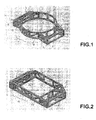
- the attachment structure 1 comprises a central portion 2 circular and two side portions 3 and 4 diametrically opposite.
- the central portion 2 consists of two elongated elements 5 curved in circles of the same diameter with half-circle profile connected by segments of straight and vertical bars 6, some of these bars such that the elements 7 are arranged obliquely so as to stiffen the structure.
- the lateral parts 3 and 4 consist of segments of bars 8. These are of different lengths and assembled so as to form kinds of rigid cages of slightly trapezoidal shape in plan, connected to the circular frames 5. These are closed on themselves and the elements 6, 7 and 8 are fixed at their ends, which gives the assembly of the attachment device a particularly rigid lattice structure even if the elements are very thin in their ratio section length.
- the constituent elements of the described structure are rigidly fixed to each other by their ends either by bonding or by welding, including mechanical welding.
- the fastening structure 1 can be made by molding. It will be noted that in each of the lateral parts 3 and 4, two elements 8 arranged vertically on the outer side have, facing each other, bosses 9 with an internal housing. These coaxial housings are intended to receive the ends of a conventional bar for connecting a strand of the bracelet.
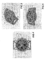
- an attachment device 10 corresponding to the second embodiment is provided to receive a rectangular box. It has a structure similar to that of the device 1, that is to say comprising on the one hand two rectangular frames 11 connected by segments of vertical bars 12 or arranged in oblique spacers like the elements 13, so as to form a central portion 14 adapted to receive a closed box, and secondly two side portions 15 in the form of perforated cages and provided with receptacles 16 with coaxial housings for the engagement of the ends of the bars.
- the elements of the frames 11 and the bars 12, 13 of the central portion 14 and the side portions 15 are all rectilinear. Their profile is in a semicircle apart for certain elements of the lateral parts which are circular. These profiles could also be oval or polygonal.
- the attachment device 1 of the Fig. 1 is represented again at Fig. 3, 4 and 5 , this time equipped with a closed box 17 adjusted to the dimensions of the central portion 2.
- the box 17 comprises in particular a cylindrical side wall 18 acting as the middle of the classic boxes, to which is fixed a window 19 which covers a dial 20 mounted on the watch movement housed in the box.
- a chronograph movement and it is not necessary to describe the functions in detail.
- the usual control members namely the time-setting ring 21 and the locking and stop / return-to-zero pushbuttons 22, 23, are constructed so as to be able to be mounted on the middle part 18 after engagement. of the box 17 inside the part 2, between the frames 5.
- the uprights 6 placed on the right side, or three hours in the attachment device are sufficiently spaced to allow this operation .
- the struts of the fastening structure comprise elements 7 oblique, or even ( Fig. 1
- the box 17 will be fixed in the central part 2 of the fastening device by any suitable means, permanently or so as to allow its extraction. It will include a removable bottom, screwed or notch giving access to the movement. All the usual techniques of carrying out the movement, the indicator organs and the casing can be used without difficulty here.
- the Fig. 6 and 7 illustrate a variant of the exemplary execution of the wristwatch of the first embodiment with its bracelet.
- the watch case is made of sapphire, so transparent.
- the Fig. 6 and 7 also show the two strands 24 of the bracelet, connected by conventional bars to the lateral parts 3 and 4 in the housings 9.
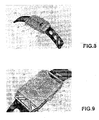
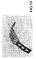
- the Fig. 8, 9 and 10 are overviews of the wristwatch according to the second embodiment with the attachment device 10 of the Fig. 2 , a closed box 25 of rectangular shape engaged in the central portion 14 and two bracelet strands 26 connected to the side portions 15.
- the movement housed in the box 25 is here a usual watch movement with a single control member is a setting ring 27, also used as winding in the case of a mechanical movement. This ring will be placed between two vertical bars 12 after engagement of the box in the fastening device.
- Fig. 11 and 12 are perspective views of another embodiment of the fastening device for a square shaped watch case. On these views, the box 30 is shown without movement, background or dial.
- the fastening structure has a triangular section forming pyramidal elements at each corner of the watch.
- the side portions 3 and 4 for the attachment of the bracelet are very simplified, their size is minimum.
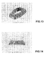
- FIG. 13 and 14 Yet another embodiment of the fastening structure is shown in Fig. 13 and 14 for a box 40 of curved lateral shape, the fastening structure 1 being in this case made to give a barrel-shaped outer shape.
- the described wristwatch is characterized by its original aesthetic giving it a very light appearance even in the case of a chronograph watch of robust construction.
- the perforated fastening device entirely formed of segments of profiled bars is an inexpensive embodiment allowing in particular the use of precious metals.
- this construction is very rigid and robust, albeit light.
- the invention applies, of course, to any timepiece comprising a movement placed in a closed box, this box being itself fixed to a support device distinct from the box, but surrounding it, such as clocks, clocks, clocks and table watches or intended to be integrated into cars and other land, sea or air vehicles.
Landscapes
- Physics & Mathematics (AREA)
- General Physics & Mathematics (AREA)
- Engineering & Computer Science (AREA)
- Manufacturing & Machinery (AREA)
- Electric Clocks (AREA)
- Adornments (AREA)
- Casings For Electric Apparatus (AREA)
Description
- La présente invention concerne les pièces d'horlogerie, et en particulier les montres-bracelets, dans lesquelles le mouvement est placé dans une boîte fermée et cette boîte est elle-même fixée à un dispositif de support, et en particulier un dispositif d'attache au bracelet dans le cas des montres-bracelets, ce dispositif étant distinct de la boîte, mais l'entourant.
- Dans la plupart des montres-bracelets connues actuellement, on trouve un organe unique appelé le boîtier, qui cumule les deux fonctions consistant à maintenir le mouvement enfermé dans un espace clos, en général étanche, et à le relier au bracelet afin de permettre de porter la montre aisément au poignet. Toutefois, on connaît aussi de nombreuses réalisations dans lesquelles ces deux fonctions sont séparées afin de répondre à différents besoins tels que simplification de la fabrication de la boîte, variation de l'esthétique du dispositif d'attache, amélioration des propriétés d'étanchéité, etc. La demande de brevet allemand
DE 10305305 A1 décrit une montre-bracelet de ce type, mais celle-ci ne répond que partiellement aux impératifs indiqués. Le brevet américainUS 5,652,736 décrit une montre-bracelet sur laquelle est attaché un récipient ornemental, ladite montre divulguant les caractéristiques techniques du préambule de la revendication 1. - Le but de la présente invention est de créer une pièce d'horlogerie, et en particulier une montre-bracelet, du genre mentionné au début, qui réponde à ces impératifs mieux que les pièces d'horlogerie déjà connues.
- Dans ce but, la présente invention concerne une pièce d'horlogerie telle que définie dans la revendication 1.
- D'autres variantes de l'invention sont également définies dans les revendications 2 à 10.
- On décrit ci-après, à titre d'exemples, diverses formes d'exécution de montres-bracelets selon l'invention et quelques variantes, en se référant aux dessins annexés, dont :
- Les
fig. 1 et 2 sont des vues en perspective du dispositif d'attache au bracelet, respectivement dans la première et la seconde des formes d'exécution données en exemple, - Les
fig. 3, 4 et 5 sont des vues également en perspective de la première forme d'exécution de la montre, sans le bracelet, - Les
fig. 6 et 7 sont des vues en perspective d'une variante de la première forme d'exécution avec le bracelet, - Les
fig. 8, 9 et10 sont des vues en perspective de la seconde forme d'exécution de la montre avec son bracelet, - Les
fig. 11 et 12 sont des vues en perspective d'une autre forme d'exécution carrée du dispositif d'attache, - Les
fig. 13 et 14 sont des vues en perspective d'une forme d'exécution ovale du dispositif d'attache, et - La
fig. 15 est une vue en perspective d'une montre comportant un dispositif d'attache selon une autre forme d'exécution. - Une particularité remarquable de la montre, dont plusieurs formes d'exécution sont représentées au dessin, est la structure du dispositif d'attache au bracelet. Les
fig. 1 et 2 représentent cette structure dans son application à une montre ronde et à une montre rectangulaire, respectivement. Dans les deux cas, le dispositif d'attache est entièrement formé d'éléments allongés ayant une section et un profil invariables sur toute leur longueur, ce qui permet une préfabrication simple et rationnelle. Ces éléments profilés peuvent être en matière plastique ou en métal, notamment en or, réalisés à base de pierres précieuses ou semi-précieuses, ou à base d'une combinaison desdits matières et éléments. Ils peuvent être recouverts de pierres précieuses ou semi-précieuses, par exemple de diamants. Ils peuvent être de sections circulaires, semi-circulaires, ou polygonales suivant les cas. Ils peuvent être constitués par des tubes pleins ou creux. Dans le cas de tubes creux, ceux-ci peuvent contenir un liquide, par exemple un liquide contenant des particules en suspension, notamment fluorescentes, ou toute autre composition destinée à créer un effet ludique, décoratif et/ou esthétique. - A la
fig. 1 , la structure d'attache 1 comporte une partie centrale 2 circulaire et deux parties latérales 3 et 4 diamétralement opposées. La partie centrale 2 est constituée de deux éléments allongés 5 incurvés en cercles de même diamètre à profil en demi-cercles reliés par des segments de barreaux 6 rectilignes et verticaux, certains de ces barreaux tels que les éléments 7 étant disposés obliquement de manière à rigidifier la structure. Les parties latérales 3 et 4 sont constituées de segments de barreaux 8. Ceux-ci sont de différentes longueurs et assemblés de manière à former des sortes de cages rigides de forme légèrement trapézoïdale en plan, reliées aux cadres circulaires 5. Ces derniers sont fermés sur eux-mêmes et les éléments 6, 7 et 8 leur sont fixés par leurs extrémités, ce qui donne à l'ensemble du dispositif d'attache une structure de treillis particulièrement rigide même si les éléments sont très effilés dans leur rapport longueur sur section. Les éléments constitutifs de la structure décrite sont rigidement fixés les uns aux autres par leurs extrémités soit par collage soit par soudage, notamment mécano-soudage. Selon un mode de fabrication avantageux, la structure d'attache 1 peut être réalisée par moulage. On notera que, dans chacune des parties latérales 3 et 4, deux éléments 8 disposés verticalement du côté extérieur présentent, tournés l'un vers l'autre, des bossages 9 avec un logement interne. Ces logements coaxiaux sont destinés à recevoir les extrémités d'une barrette usuelle pour la liaison à un brin du bracelet. - A la
fig. 2 , un dispositif d'attache 10 correspondant à la seconde forme d'exécution est prévu pour recevoir une boîte rectangulaire. Il présente une structure similaire à celle du dispositif 1, c'est-à-dire comportant d'une part deux cadres 11 rectangulaires reliés par des segments de barreaux 12 verticaux ou disposés en entretoises obliques comme les éléments 13, de manière à former une partie centrale 14 apte à recevoir une boîte fermée, et d'autre part deux parties latérales 15 en formes de cages ajourées et munies de réceptacles 16 à logements coaxiaux pour l'engagement des extrémités des barrettes. Les éléments des cadres 11 ainsi que les barreaux 12, 13 de la partie centrale 14 et des parties latérales 15 sont tous rectilignes. Leur profil est en demi-cercle à part pour certains éléments des parties latérales qui sont circulaires. Ces profils pourraient aussi être ovales ou polygonaux. - Le dispositif d'attache 1 de la
fig. 1 est représenté à nouveau auxfig. 3, 4 et 5 , cette fois équipé d'une boîte fermée 17 ajustée aux dimensions de la partie centrale 2. La boîte 17 comporte notamment une paroi latérale cylindrique 18 jouant le rôle de la carrure des boîtes classiques, à laquelle est fixée une glace 19 qui recouvre un cadran 20 monté sur le mouvement de montre logé dans la boîte. Dans le cas desfig. 3, 4 et 5 , il s'agit d'un mouvement de chronographe dont il n'est pas nécessaire de décrire les fonctions en détail. On notera cependant que les organes de commande usuels, soit couronne de mise à l'heure 21 et poussoirs d'enclenchement et d'arrêt/retour à zéro 22, 23, sont construits de manière à pouvoir être montés sur la carrure 18 après engagement de la boîte 17 à l'intérieur de la partie 2, entre les cadres 5. A cet effet, les montants verticaux 6 placés sur la partie droite, soit sur trois heures dans le dispositif d'attache, sont suffisamment écartés pour permettre cette opération. Comme on le voit à lafig. 5 , sur le côté gauche, soit sur neuf heures, les entretoises de la structure d'attache comportent des éléments 7 en oblique, ou même (fig. 1 ) en X. La boîte 17 sera fixée dans la partie centrale 2 du dispositif d'attache par tout moyen convenable, à demeure ou de façon à permettre son extraction. Elle comportera un fond amovible, vissé ou à cran donnant accès au mouvement. Toutes les techniques habituelles de réalisation du mouvement, des organes indicateurs et de l'emboîtage sont utilisables sans difficulté ici. - Les
fig. 6 et 7 illustrent une variante de l'exemple d'exécution de la montre-bracelet de la première forme d'exécution avec son bracelet. Dans cette variante, la boîte de la montre est réalisée en saphir, donc transparente. Lesfig. 6 et 7 montrent aussi les deux brins 24 du bracelet, raccordés par des barrettes usuelles aux parties latérales 3 et 4 dans les logements 9. - Les
fig. 8, 9 et10 sont des vues d'ensemble de la montre-bracelet selon la seconde forme d'exécution avec le dispositif d'attache 10 de lafig. 2 , une boîte fermée 25 de forme rectangulaire engagée dans la partie centrale 14 et deux brins de bracelet 26 reliés aux parties latérales 15. Le mouvement logé dans la boîte 25 est ici un mouvement de montre usuel avec un seul organe de commande soit une couronne de mise à l'heure 27, servant aussi de remontoir dans le cas d'un mouvement mécanique. Cette couronne sera mise en place entre deux barreaux 12 verticaux après engagement de la boîte dans le dispositif d'attache. - Les
fig. 11 et 12 sont des vues en perspective d'une autre forme d'exécution du dispositif d'attache pour une boîte de montre de forme carrée. Sur ces vues, la boîte 30 est représentée sans mouvement, ni fond, ni cadran. Dans ce mode d'exécution, la structure d'attache présente une section triangulaire formant des éléments pyramidaux à chacun des coins de la montre. De plus, les parties latérales 3 et 4 pour l'attache du bracelet sont très simplifiées, leur encombrement étant minimum. - Encore une autre forme de réalisation de la structure d'attache est représentée aux
fig. 13 et 14 pour une boîte 40 de forme latérale bombée, la structure d'attache 1 étant dans ce cas réalisée de façon à donner une forme extérieure en forme de tonneau. - Dans l'ensemble, la montre-bracelet décrite se caractérise par son esthétique originale lui conférant un aspect de grande légèreté même dans le cas d'une montre-chronographe de construction robuste. Le dispositif d'attache ajouré, entièrement formé de segments de barreaux en profilés est d'une réalisation peu coûteuse permettant notamment l'utilisation de métaux précieux. De plus, cette construction se révèle très rigide et robuste, quoique légère.
- D'autres formes d'exécution sont encore possibles en développant l'idée d'un dispositif d'attache construit par utilisation d'éléments profilés filiformes selon les figures décrites ci-dessus pour obtenir une structure ajourée. Par exemple, un fil roulé en ressort à boudin et fermé sur lui-même en cercle, comme représenté à la
fig. 15 , ou en rectangle, pourrait constituer la partie centrale du dispositif d'attache du bracelet. L'homme du métier pourra encore imaginer des solutions variées dans cette optique. - Bien que les exemples décrits ci-dessus concernent tous des montres-bracelets, l'invention s'applique bien entendu à toute pièce d'horlogerie comportant un mouvement placé dans une boîte fermée, cette boîte étant elle-même fixée à un dispositif de support distinct de la boîte, mais l'entourant, telles que pendules, horloges, pendulettes et montres de tables ou destinées à être intégrées dans les voitures et autres véhicules terrestres, maritimes ou aériens.
Claims (9)
- Pièce d'horlogerie comportant une boîte fermée contenant un mouvement et un dispositif de support auquel ladite boîte est fixée, ledit dispositif de support étant une structure ajourée rigide en forme de treillis ou de spirale qui entoure les côtés de la boîte, caractérisée en ce que ledit dispositif de support comporte une partie centrale (2, 14) comportant deux cadres (5; 11) reliés par des segments de barreaux (6, 7; 12) disposés en entretoises entre les cadres, et en ce que la boîte (17; 25) est engagée dans les deux cadres et fixée à au moins un de ces derniers.
- Pièce d'horlogerie selon la revendication 1, caractérisée en ce que les constituants (5, 6, 7, 8; 11, 12, 13) de ladite structure ajourée sont fixés les uns aux autres par leurs extrémités par collage ou mécano-soudage.
- Pièce d'horlogerie selon la revendication 1, caractérisée en ce que lesdits segments de barreaux (6, 7, 8; 12, 13) sont rectilignes.
- Pièce d'horlogerie selon la revendication 1, caractérisée en ce qu'au moins une partie desdite segments de barreaux eat incurvée.
- Pièce d'horlogerie selon l'une des revendications précédentes, caractérisée en ce qu'il s'agit d'une montre-bracelet et en ce que ladite structure ajourée constitue le dispositif d'attache du bracelet et comporte, outre la partie centrale (2; 14) qui entoure et fixe la boîte (17; 25), deux parties latérales opposées (3, 4, 15) munies de moyens de liaison (9; 16) au bracelet (24; 26).
- Pièce d'horlogerie selon la revendication précédente, caractérisée en ce que la structure ajourée est une structure de treillis.
- Pièce d'horlogerie selon l'une des revendications 5 ou 6, caractérisée en ce qu'au moins un organe de commande manuelle (21, 22, 23; 27) de fonction du mouvement est monté de manière amovible sur un côté de la boîte (17; 25) et en ce que ladite structure ajourée ménage dans ladite partie centrale annulaire (2; 14) au moins une ouverture permettant la mise en place du ou desdits organe(s) de commande.
- Pièce d'horlogerie selon l'une des revendications 5 à 7, caractérisée en ce que chacune desdites parties latérales (3, 4; 15) comporte dans sa structure deux réceptacles (9; 16) avec logements coaxiaux pour les extrémités d'une barrette.
- Pièce d'horlogerie selon l'une des revendications précédentes, caractérisée en ce que la structure ajourée est formée de tubes creux.
Applications Claiming Priority (2)
| Application Number | Priority Date | Filing Date | Title |
|---|---|---|---|
| CH16342006 | 2006-10-13 | ||
| PCT/IB2007/054161 WO2008044220A2 (fr) | 2006-10-13 | 2007-10-12 | Piece d'horlogerie |
Publications (3)
| Publication Number | Publication Date |
|---|---|
| EP2074484A2 EP2074484A2 (fr) | 2009-07-01 |
| EP2074484B1 EP2074484B1 (fr) | 2012-07-04 |
| EP2074484B9 true EP2074484B9 (fr) | 2012-09-19 |
Family
ID=39278343
Family Applications (1)
| Application Number | Title | Priority Date | Filing Date |
|---|---|---|---|
| EP07826725A Not-in-force EP2074484B9 (fr) | 2006-10-13 | 2007-10-12 | Piece d'horlogerie |
Country Status (4)
| Country | Link |
|---|---|
| US (1) | US8579500B2 (fr) |
| EP (1) | EP2074484B9 (fr) |
| CN (1) | CN101632049B (fr) |
| WO (1) | WO2008044220A2 (fr) |
Families Citing this family (15)
| Publication number | Priority date | Publication date | Assignee | Title |
|---|---|---|---|---|
| US8303169B2 (en) * | 2011-01-21 | 2012-11-06 | Bulltoro Watch Company, LLC | Comfort watch |
| US9477320B2 (en) * | 2011-08-16 | 2016-10-25 | Argotext, Inc. | Input device |
| WO2013033666A1 (fr) * | 2011-09-01 | 2013-03-07 | Stefan Johansson | Boîtier de montre à poussoir et couronne intégrés |
| CN103082591B (zh) * | 2011-10-27 | 2014-07-16 | 天津海鸥表业集团有限公司 | 一种饰品表表头的连接装置 |
| WO2014044247A2 (fr) * | 2012-09-24 | 2014-03-27 | H.T.C. Energy Pictures & Records Foundation Representation Germany | Mouvement d'horlogerie |
| CN102981392B (zh) * | 2012-11-30 | 2016-07-27 | 邓湘凌 | 镂空陶瓷表壳的制作方法 |
| JP1538865S (fr) * | 2014-10-01 | 2015-11-30 | ||
| USD867165S1 (en) * | 2015-05-19 | 2019-11-19 | Jacob & Co Sa | Watch |
| JP1599863S (fr) * | 2017-03-09 | 2018-03-19 | ||
| USD900091S1 (en) * | 2017-06-13 | 2020-10-27 | Ogio International, Inc. | Fit disc |
| USD824785S1 (en) * | 2017-09-27 | 2018-08-07 | Vishal Tolani | Watch case |
| DE102017130975A1 (de) * | 2017-12-21 | 2019-06-27 | AL-TIME GmbH | Trägergehäuse für eine Aufnahme eines Laufwerkgehäuses einer Armbanduhr |
| IT201900004759A1 (it) * | 2019-03-29 | 2020-09-29 | La Vallee S R L | Struttura di supporto per orologeria ed orologio comprendente tale struttura |
| JP7296045B2 (ja) * | 2020-12-18 | 2023-06-22 | カシオ計算機株式会社 | 外装装置及び腕時計 |
| CN218446386U (zh) * | 2022-10-28 | 2023-02-03 | 乳圆数字科技(深圳)有限公司 | 一种金属轮转动装置 |
Family Cites Families (23)
| Publication number | Priority date | Publication date | Assignee | Title |
|---|---|---|---|---|
| US1199256A (en) * | 1916-02-03 | 1916-09-26 | Frank Farr | Watch-face protector. |
| GB106357A (en) * | 1916-07-07 | 1917-05-24 | Frederick Smails | Adjustable Watch Wristlet-guard. |
| US1853483A (en) * | 1929-10-12 | 1932-04-12 | Frank A Winters | Watch supporting bracket |
| US1789602A (en) * | 1929-11-30 | 1931-01-20 | Siptrott Paul | Clock frame and method of making same |
| US2565822A (en) * | 1949-11-21 | 1951-08-28 | James F Mcclelland | Watch guard and band |
| US3191901A (en) * | 1962-11-05 | 1965-06-29 | James W Green | Ornamental watch, portrait and plaque stand |
| CH642810B (fr) * | 1981-12-02 | Rado Montres Sa | Boite de montre. | |
| US4525077A (en) * | 1982-01-05 | 1985-06-25 | Ketner Eugene N | Timepiece having central opening |
| US4627739A (en) * | 1984-02-03 | 1986-12-09 | Citizen Watch Co., Ltd. | Bracelet type wrist watch |
| JPS6123989A (ja) * | 1984-07-11 | 1986-02-01 | Itsupongi Koubou:Kk | 腕時計用ケ−ス |
| US4837756A (en) * | 1987-02-27 | 1989-06-06 | James Hartman | Perimetrical watch protector |
| USD312980S (en) * | 1987-06-11 | 1990-12-18 | Cadio Computer Co., Ltd. | Protector for wrist watch |
| US4835750A (en) * | 1988-02-01 | 1989-05-30 | Q.S. International, Ltd. | Wristwatch guard |
| FR2665546B1 (fr) * | 1990-08-01 | 1995-04-21 | Boucheron | Montre-bracelet avec boitier a couvercle interchangeable. |
| US5442602A (en) * | 1993-08-25 | 1995-08-15 | Casio Computer Co., Ltd. | Wristwatch case with shock absorbing members on the rear side thereof |
| US5848030A (en) * | 1995-12-29 | 1998-12-08 | Sullivan; Scott L. | Watch and watchband arrangement |
| US5652736A (en) | 1996-06-17 | 1997-07-29 | Lee; Vincent Kuo Wei | Ornamental container detachably attached to wrist watch |
| WO1998014839A1 (fr) * | 1996-10-03 | 1998-04-09 | Comadur S.A. | Boite de montre comportant une enveloppe et un dispositif de support |
| KR100454764B1 (ko) * | 2001-09-26 | 2004-11-05 | 주식회사 와이.비 인터내셔날 | 하부 뚜껑이 없는 본체 케이스와 보조 케이스로 조립된손목시계 |
| USD474698S1 (en) * | 2002-04-05 | 2003-05-20 | Parmigiani Mesure Et Art Du Temps Sa | Watch case |
| DE10305305A1 (de) | 2003-02-10 | 2004-09-02 | Junghans Uhren Gmbh | Gehäusemittelteil für eine Armbanduhr sowie Verfahren zu dessen Herstellung |
| CN2727817Y (zh) * | 2004-08-24 | 2005-09-21 | 广州手表厂 | 手表壳 |
| DE202006013444U1 (de) * | 2006-09-01 | 2006-12-21 | Franz, Elisabeth | Uhrengehäuse |
-
2007
- 2007-10-12 EP EP07826725A patent/EP2074484B9/fr not_active Not-in-force
- 2007-10-12 CN CN200780045347.6A patent/CN101632049B/zh not_active Expired - Fee Related
- 2007-10-12 WO PCT/IB2007/054161 patent/WO2008044220A2/fr active Application Filing
- 2007-10-12 US US12/311,763 patent/US8579500B2/en active Active
Also Published As
| Publication number | Publication date |
|---|---|
| CN101632049B (zh) | 2014-04-16 |
| WO2008044220A3 (fr) | 2008-06-26 |
| US8579500B2 (en) | 2013-11-12 |
| EP2074484A2 (fr) | 2009-07-01 |
| EP2074484B1 (fr) | 2012-07-04 |
| US20100135128A1 (en) | 2010-06-03 |
| CN101632049A (zh) | 2010-01-20 |
| WO2008044220A2 (fr) | 2008-04-17 |
Similar Documents
| Publication | Publication Date | Title |
|---|---|---|
| EP2074484B9 (fr) | Piece d'horlogerie | |
| WO1998014839A1 (fr) | Boite de montre comportant une enveloppe et un dispositif de support | |
| CH678254B5 (fr) | ||
| EP0437560B1 (fr) | Piece de bijouterie, notamment d'horlogerie a presentation modifiable | |
| EP1047982A1 (fr) | Boite de montre | |
| EP1133935B1 (fr) | Montre-bracelet et bracelet susceptible d'équiper une telle montre | |
| EP0626625B1 (fr) | Boîte de montre en métal noble | |
| EP0099150B1 (fr) | Boîte de montre bracelet munie d'un bracelet intégré | |
| FR2776785A1 (fr) | Ensemble constitutif de l'habillement d'une montre | |
| CH456960A (de) | Verfahren zur Abtrennung von Poly-1-olefinen aus Lösungen in ihren flüssigen 1-Olefinmonomeren | |
| EP1241541B1 (fr) | Boîte de montre assemblée par la lunette | |
| CH672224B5 (fr) | ||
| FR2715806A1 (fr) | Bijoux transformables de forme courbe. | |
| EP3236321A1 (fr) | Boîte de montre asymétrique | |
| CH682290A5 (en) | Wrist watch bracelet - has holder between two sections of bracelet on opposite side to watch, designed to hold second instrument or container | |
| EP0869414B1 (fr) | Boíte de montre | |
| CH712372B1 (fr) | Montre-bracelet ou montre de poche incluant un dispositif d'affichage. | |
| EP0082840B1 (fr) | Boite de montre etanche | |
| FR2507348A1 (fr) | Ensemble plaque de cadran et boite de dispositif d'horlogerie et leur procede d'assemblage | |
| CH371055A (fr) | Boîte de montre-bracelet | |
| CH340189A (fr) | Article à face animée | |
| WO2000057250A1 (fr) | Montre a elements interchangeables | |
| CH690871A5 (fr) | Montre-bracelet. | |
| CH714263B1 (fr) | Boîtier montre-bracelet. | |
| CH243632A (fr) | Boîte de montre. |
Legal Events
| Date | Code | Title | Description |
|---|---|---|---|
| PUAI | Public reference made under article 153(3) epc to a published international application that has entered the european phase |
Free format text: ORIGINAL CODE: 0009012 |
|
| 17P | Request for examination filed |
Effective date: 20090424 |
|
| AK | Designated contracting states |
Kind code of ref document: A2 Designated state(s): AT BE BG CH CY CZ DE DK EE ES FI FR GB GR HU IE IS IT LI LT LU LV MC MT NL PL PT RO SE SI SK TR |
|
| 17Q | First examination report despatched |
Effective date: 20100318 |
|
| DAX | Request for extension of the european patent (deleted) | ||
| REG | Reference to a national code |
Ref country code: DE Ref legal event code: R079 Ref document number: 602007023828 Country of ref document: DE Free format text: PREVIOUS MAIN CLASS: G04B0037000000 Ipc: G04B0037220000 |
|
| GRAP | Despatch of communication of intention to grant a patent |
Free format text: ORIGINAL CODE: EPIDOSNIGR1 |
|
| RIC1 | Information provided on ipc code assigned before grant |
Ipc: G04B 45/00 20060101ALI20111201BHEP Ipc: G04B 37/22 20060101AFI20111201BHEP Ipc: G04B 37/00 20060101ALI20111201BHEP |
|
| GRAS | Grant fee paid |
Free format text: ORIGINAL CODE: EPIDOSNIGR3 |
|
| GRAA | (expected) grant |
Free format text: ORIGINAL CODE: 0009210 |
|
| AK | Designated contracting states |
Kind code of ref document: B1 Designated state(s): AT BE BG CH CY CZ DE DK EE ES FI FR GB GR HU IE IS IT LI LT LU LV MC MT NL PL PT RO SE SI SK TR |
|
| REG | Reference to a national code |
Ref country code: GB Ref legal event code: FG4D Free format text: NOT ENGLISH |
|
| REG | Reference to a national code |
Ref country code: CH Ref legal event code: EP |
|
| REG | Reference to a national code |
Ref country code: AT Ref legal event code: REF Ref document number: 565379 Country of ref document: AT Kind code of ref document: T Effective date: 20120715 |
|
| REG | Reference to a national code |
Ref country code: IE Ref legal event code: FG4D Free format text: LANGUAGE OF EP DOCUMENT: FRENCH |
|
| REG | Reference to a national code |
Ref country code: DE Ref legal event code: R096 Ref document number: 602007023828 Country of ref document: DE Effective date: 20120830 |
|
| REG | Reference to a national code |
Ref country code: CH Ref legal event code: NV Representative=s name: ABREMA AGENCE BREVET ET MARQUES, GANGUILLET |
|
| REG | Reference to a national code |
Ref country code: AT Ref legal event code: MK05 Ref document number: 565379 Country of ref document: AT Kind code of ref document: T Effective date: 20120704 |
|
| REG | Reference to a national code |
Ref country code: NL Ref legal event code: VDEP Effective date: 20120704 |
|
| PG25 | Lapsed in a contracting state [announced via postgrant information from national office to epo] |
Ref country code: SI Free format text: LAPSE BECAUSE OF FAILURE TO SUBMIT A TRANSLATION OF THE DESCRIPTION OR TO PAY THE FEE WITHIN THE PRESCRIBED TIME-LIMIT Effective date: 20120704 |
|
| REG | Reference to a national code |
Ref country code: LT Ref legal event code: MG4D Effective date: 20120704 |
|
| PG25 | Lapsed in a contracting state [announced via postgrant information from national office to epo] |
Ref country code: AT Free format text: LAPSE BECAUSE OF FAILURE TO SUBMIT A TRANSLATION OF THE DESCRIPTION OR TO PAY THE FEE WITHIN THE PRESCRIBED TIME-LIMIT Effective date: 20120704 Ref country code: CY Free format text: LAPSE BECAUSE OF FAILURE TO SUBMIT A TRANSLATION OF THE DESCRIPTION OR TO PAY THE FEE WITHIN THE PRESCRIBED TIME-LIMIT Effective date: 20120704 Ref country code: LT Free format text: LAPSE BECAUSE OF FAILURE TO SUBMIT A TRANSLATION OF THE DESCRIPTION OR TO PAY THE FEE WITHIN THE PRESCRIBED TIME-LIMIT Effective date: 20120704 Ref country code: FI Free format text: LAPSE BECAUSE OF FAILURE TO SUBMIT A TRANSLATION OF THE DESCRIPTION OR TO PAY THE FEE WITHIN THE PRESCRIBED TIME-LIMIT Effective date: 20120704 Ref country code: IS Free format text: LAPSE BECAUSE OF FAILURE TO SUBMIT A TRANSLATION OF THE DESCRIPTION OR TO PAY THE FEE WITHIN THE PRESCRIBED TIME-LIMIT Effective date: 20121104 |
|
| PG25 | Lapsed in a contracting state [announced via postgrant information from national office to epo] |
Ref country code: SE Free format text: LAPSE BECAUSE OF FAILURE TO SUBMIT A TRANSLATION OF THE DESCRIPTION OR TO PAY THE FEE WITHIN THE PRESCRIBED TIME-LIMIT Effective date: 20120704 Ref country code: PT Free format text: LAPSE BECAUSE OF FAILURE TO SUBMIT A TRANSLATION OF THE DESCRIPTION OR TO PAY THE FEE WITHIN THE PRESCRIBED TIME-LIMIT Effective date: 20121105 Ref country code: PL Free format text: LAPSE BECAUSE OF FAILURE TO SUBMIT A TRANSLATION OF THE DESCRIPTION OR TO PAY THE FEE WITHIN THE PRESCRIBED TIME-LIMIT Effective date: 20120704 Ref country code: LV Free format text: LAPSE BECAUSE OF FAILURE TO SUBMIT A TRANSLATION OF THE DESCRIPTION OR TO PAY THE FEE WITHIN THE PRESCRIBED TIME-LIMIT Effective date: 20120704 Ref country code: GR Free format text: LAPSE BECAUSE OF FAILURE TO SUBMIT A TRANSLATION OF THE DESCRIPTION OR TO PAY THE FEE WITHIN THE PRESCRIBED TIME-LIMIT Effective date: 20121005 |
|
| PG25 | Lapsed in a contracting state [announced via postgrant information from national office to epo] |
Ref country code: NL Free format text: LAPSE BECAUSE OF FAILURE TO SUBMIT A TRANSLATION OF THE DESCRIPTION OR TO PAY THE FEE WITHIN THE PRESCRIBED TIME-LIMIT Effective date: 20120704 |
|
| BERE | Be: lapsed |
Owner name: PENULA, JOSEPH Effective date: 20121031 |
|
| PG25 | Lapsed in a contracting state [announced via postgrant information from national office to epo] |
Ref country code: ES Free format text: LAPSE BECAUSE OF FAILURE TO SUBMIT A TRANSLATION OF THE DESCRIPTION OR TO PAY THE FEE WITHIN THE PRESCRIBED TIME-LIMIT Effective date: 20121015 Ref country code: DK Free format text: LAPSE BECAUSE OF FAILURE TO SUBMIT A TRANSLATION OF THE DESCRIPTION OR TO PAY THE FEE WITHIN THE PRESCRIBED TIME-LIMIT Effective date: 20120704 Ref country code: RO Free format text: LAPSE BECAUSE OF FAILURE TO SUBMIT A TRANSLATION OF THE DESCRIPTION OR TO PAY THE FEE WITHIN THE PRESCRIBED TIME-LIMIT Effective date: 20120704 Ref country code: EE Free format text: LAPSE BECAUSE OF FAILURE TO SUBMIT A TRANSLATION OF THE DESCRIPTION OR TO PAY THE FEE WITHIN THE PRESCRIBED TIME-LIMIT Effective date: 20120704 Ref country code: CZ Free format text: LAPSE BECAUSE OF FAILURE TO SUBMIT A TRANSLATION OF THE DESCRIPTION OR TO PAY THE FEE WITHIN THE PRESCRIBED TIME-LIMIT Effective date: 20120704 |
|
| PLBE | No opposition filed within time limit |
Free format text: ORIGINAL CODE: 0009261 |
|
| STAA | Information on the status of an ep patent application or granted ep patent |
Free format text: STATUS: NO OPPOSITION FILED WITHIN TIME LIMIT |
|
| PG25 | Lapsed in a contracting state [announced via postgrant information from national office to epo] |
Ref country code: SK Free format text: LAPSE BECAUSE OF FAILURE TO SUBMIT A TRANSLATION OF THE DESCRIPTION OR TO PAY THE FEE WITHIN THE PRESCRIBED TIME-LIMIT Effective date: 20120704 Ref country code: MC Free format text: LAPSE BECAUSE OF NON-PAYMENT OF DUE FEES Effective date: 20121031 |
|
| 26N | No opposition filed |
Effective date: 20130405 |
|
| REG | Reference to a national code |
Ref country code: IE Ref legal event code: MM4A |
|
| PG25 | Lapsed in a contracting state [announced via postgrant information from national office to epo] |
Ref country code: BG Free format text: LAPSE BECAUSE OF FAILURE TO SUBMIT A TRANSLATION OF THE DESCRIPTION OR TO PAY THE FEE WITHIN THE PRESCRIBED TIME-LIMIT Effective date: 20121004 Ref country code: IE Free format text: LAPSE BECAUSE OF NON-PAYMENT OF DUE FEES Effective date: 20121012 Ref country code: BE Free format text: LAPSE BECAUSE OF NON-PAYMENT OF DUE FEES Effective date: 20121031 |
|
| REG | Reference to a national code |
Ref country code: DE Ref legal event code: R097 Ref document number: 602007023828 Country of ref document: DE Effective date: 20130405 |
|
| PG25 | Lapsed in a contracting state [announced via postgrant information from national office to epo] |
Ref country code: MT Free format text: LAPSE BECAUSE OF FAILURE TO SUBMIT A TRANSLATION OF THE DESCRIPTION OR TO PAY THE FEE WITHIN THE PRESCRIBED TIME-LIMIT Effective date: 20120704 |
|
| PG25 | Lapsed in a contracting state [announced via postgrant information from national office to epo] |
Ref country code: TR Free format text: LAPSE BECAUSE OF FAILURE TO SUBMIT A TRANSLATION OF THE DESCRIPTION OR TO PAY THE FEE WITHIN THE PRESCRIBED TIME-LIMIT Effective date: 20120704 |
|
| PG25 | Lapsed in a contracting state [announced via postgrant information from national office to epo] |
Ref country code: LU Free format text: LAPSE BECAUSE OF NON-PAYMENT OF DUE FEES Effective date: 20121012 |
|
| PG25 | Lapsed in a contracting state [announced via postgrant information from national office to epo] |
Ref country code: HU Free format text: LAPSE BECAUSE OF FAILURE TO SUBMIT A TRANSLATION OF THE DESCRIPTION OR TO PAY THE FEE WITHIN THE PRESCRIBED TIME-LIMIT Effective date: 20071012 |
|
| REG | Reference to a national code |
Ref country code: CH Ref legal event code: PUE Owner name: MAXIRIS SA, CH Free format text: FORMER OWNER: PENULA, JOSEPH, US |
|
| REG | Reference to a national code |
Ref country code: CH Ref legal event code: PUE Owner name: JOSEPH PENULA, US Free format text: FORMER OWNER: MAXIRIS SA, CH |
|
| REG | Reference to a national code |
Ref country code: FR Ref legal event code: PLFP Year of fee payment: 9 |
|
| PGFP | Annual fee paid to national office [announced via postgrant information from national office to epo] |
Ref country code: GB Payment date: 20151021 Year of fee payment: 9 |
|
| REG | Reference to a national code |
Ref country code: FR Ref legal event code: PLFP Year of fee payment: 10 |
|
| REG | Reference to a national code |
Ref country code: CH Ref legal event code: AECN Free format text: LE BREVET A ETE REACTIVE SELON LA DEMANDE DE POURSUITE DE LA PROCEDURE DU 03.05.2017 Ref country code: CH Ref legal event code: PL |
|
| GBPC | Gb: european patent ceased through non-payment of renewal fee |
Effective date: 20161012 |
|
| PG25 | Lapsed in a contracting state [announced via postgrant information from national office to epo] |
Ref country code: GB Free format text: LAPSE BECAUSE OF NON-PAYMENT OF DUE FEES Effective date: 20161012 |
|
| REG | Reference to a national code |
Ref country code: FR Ref legal event code: PLFP Year of fee payment: 11 |
|
| PGFP | Annual fee paid to national office [announced via postgrant information from national office to epo] |
Ref country code: DE Payment date: 20180426 Year of fee payment: 11 |
|
| REG | Reference to a national code |
Ref country code: DE Ref legal event code: R119 Ref document number: 602007023828 Country of ref document: DE |
|
| PG25 | Lapsed in a contracting state [announced via postgrant information from national office to epo] |
Ref country code: DE Free format text: LAPSE BECAUSE OF NON-PAYMENT OF DUE FEES Effective date: 20190501 |
|
| REG | Reference to a national code |
Ref country code: CH Ref legal event code: PFUS Owner name: JOSEPH PENULA, US Free format text: FORMER OWNER: JOSEPH PENULA, US |
|
| PGFP | Annual fee paid to national office [announced via postgrant information from national office to epo] |
Ref country code: IT Payment date: 20211029 Year of fee payment: 15 Ref country code: FR Payment date: 20211029 Year of fee payment: 15 |
|
| REG | Reference to a national code |
Ref country code: CH Ref legal event code: PL |
|
| REG | Reference to a national code |
Ref country code: CH Ref legal event code: PK Free format text: LA RADIATION DU 3.5.23 A ETE PUBLIEE PAR ERREUR, L'ANNUITE AYANT ETE REGULIEREMENT PAYEE. |
|
| PG25 | Lapsed in a contracting state [announced via postgrant information from national office to epo] |
Ref country code: LI Free format text: LAPSE BECAUSE OF NON-PAYMENT OF DUE FEES Effective date: 20221031 Ref country code: FR Free format text: LAPSE BECAUSE OF NON-PAYMENT OF DUE FEES Effective date: 20221031 Ref country code: CH Free format text: LAPSE BECAUSE OF NON-PAYMENT OF DUE FEES Effective date: 20221031 |
|
| PGFP | Annual fee paid to national office [announced via postgrant information from national office to epo] |
Ref country code: CH Payment date: 20230503 Year of fee payment: 16 |
|
| PG25 | Lapsed in a contracting state [announced via postgrant information from national office to epo] |
Ref country code: IT Free format text: LAPSE BECAUSE OF NON-PAYMENT OF DUE FEES Effective date: 20221012 |