EP2073959B1 - Approaching and compensating for machine kinematic singularities - Google Patents
Approaching and compensating for machine kinematic singularities Download PDFInfo
- Publication number
- EP2073959B1 EP2073959B1 EP07837375.0A EP07837375A EP2073959B1 EP 2073959 B1 EP2073959 B1 EP 2073959B1 EP 07837375 A EP07837375 A EP 07837375A EP 2073959 B1 EP2073959 B1 EP 2073959B1
- Authority
- EP
- European Patent Office
- Prior art keywords
- joints
- linkage
- singularity
- matrix
- manipulator matrix
- Prior art date
- Legal status (The legal status is an assumption and is not a legal conclusion. Google has not performed a legal analysis and makes no representation as to the accuracy of the status listed.)
- Not-in-force
Links
- 239000011159 matrix material Substances 0.000 claims description 43
- 238000000034 method Methods 0.000 claims description 27
- 239000013598 vector Substances 0.000 claims description 25
- 238000000354 decomposition reaction Methods 0.000 claims description 10
- 238000012544 monitoring process Methods 0.000 claims description 6
- 238000013459 approach Methods 0.000 claims description 4
- 238000012545 processing Methods 0.000 claims description 4
- 238000010586 diagram Methods 0.000 description 5
- 238000009434 installation Methods 0.000 description 4
- 238000004364 calculation method Methods 0.000 description 3
- 230000033001 locomotion Effects 0.000 description 3
- 238000004422 calculation algorithm Methods 0.000 description 2
- 230000001143 conditioned effect Effects 0.000 description 2
- 230000000694 effects Effects 0.000 description 2
- 230000006870 function Effects 0.000 description 2
- 238000003754 machining Methods 0.000 description 2
- 238000012423 maintenance Methods 0.000 description 2
- 238000004519 manufacturing process Methods 0.000 description 2
- 238000012897 Levenberg–Marquardt algorithm Methods 0.000 description 1
- 238000004891 communication Methods 0.000 description 1
- 238000005520 cutting process Methods 0.000 description 1
- 230000002950 deficient Effects 0.000 description 1
- 238000003913 materials processing Methods 0.000 description 1
- 239000002699 waste material Substances 0.000 description 1
Images

Classifications
-
- B—PERFORMING OPERATIONS; TRANSPORTING
- B25—HAND TOOLS; PORTABLE POWER-DRIVEN TOOLS; MANIPULATORS
- B25J—MANIPULATORS; CHAMBERS PROVIDED WITH MANIPULATION DEVICES
- B25J9/00—Programme-controlled manipulators
- B25J9/16—Programme controls
- B25J9/1602—Programme controls characterised by the control system, structure, architecture
- B25J9/1607—Calculation of inertia, jacobian matrixes and inverses
Definitions
- the present disclosure relates to multi-axis machines and, more particularly, to systems and methods of dealing with kinematic singularities during machine operation.
- the statements in this section merely provide background information related to the present disclosure and may not constitute prior art.
- a multi-axis machine may be software-driven to move one or more machine tools relative to a work piece.
- a multi-axis kinematic linkage of the machine is capable of moving a tool relative to a plurality of predetermined coordinate axes.
- a plurality of translational and/or rotational joints may be operable singly and/or cooperatively to move one or more links to position a tool at a desired location.
- a multi-axis linkage may be moved to a position (i.e. "a singularity", or "a singular point") in which one or more degrees of freedom are lost.
- a singular point one or more joints may be incapable of moving a tool as instructed by the software.
- the present disclosure in one implementation, is directed to a method of operating a multi-axis machine.
- a kinematic linkage of the machine is monitored.
- the linkage includes a plurality of joints and links.
- the linkage is monitored to detect an approach by one or more joints of the linkage toward singularity.
- the monitoring is performed using a manipulator matrix.
- a degree n of the approached singularity is determined.
- the one or more joints approaching singularity are identified.
- the method includes obtaining n virtual joints, replacing the one or more identified joints with the virtual joints in the manipulator matrix to modify the manipulator matrix, and using the modified manipulator matrix to determine position changes for links of the linkage.
- a numerically controlled (NC) processing system in accordance with one implementation of the present disclosure is indicated generally in Figure 1 by reference number 20.
- the system 20 includes one or more multi-axis machines 24, one of which is shown in Figure 1 .
- a machine 24 may be configured, for example, to perform multi-axis machining operations on a work piece (not shown). Additionally or alternatively, the system 20 may include other types of multi-axis machines capable of component placement, for example, a numerically controlled assembly robot.
- the system 20 includes one or more computers 28, one of which is shown in Figure 1 .
- the computer 28 includes a suitably programmed computer processor 32 and memory 36.
- the computer 28 may be programmed in accordance with one implementation of the disclosure to monitor and control operation of the multi-axis machine 24.
- the computer 28 may be used to execute software for adjustably compensating the positioning of the multi-axis machine 24, as further described below.
- Software compensation may be used, e.g., to adjust for certain "as-built" conditions of the machine 24 in order to bring operation of the machine 24 within tolerances specified relative to an ideal or "perfect" machine.
- a user interface 40 such as a computer terminal including a keyboard, pointing device, and monitor, is provided by which a user may communicate with the system 20.
- a user interface 40 such as a computer terminal including a keyboard, pointing device, and monitor, is provided by which a user may communicate with the system 20.
- the present disclosure could be implemented relative to many and various kinds of installations, including but not limited to materials processing installation configurations described in U.S. Patent Publication No. 20060271241 . It shall be understood by those skilled in the art that many different types and configurations of multi-axis machines, computers, processors, input-output devices, communication systems, etc., could be included in NC processing systems in accordance with various implementations of the disclosure.
- a portion of a multi-axis kinematic linkage of the machine 24 is indicated generally in Figure 2 by reference number 100.
- the linkage 100 includes six movable links 108a-108f interconnected by six joints 112a-112f. Joints 112a-112e are revolute (i.e. rotary) and joint 112f is prismatic (i.e. sliding).
- the linkage 100 is operable by the computer 28 to position and control a tip portion 116 along a predefined path during a work process.
- the tip portion 116 may have, e.g ., a cutting tool or other type of tool (not shown) mounted thereon.
- the linkage 100 is exemplary only.
- Machines 24 may have linkages more or less complex than the linkage 100 and may include more, fewer and/or different types of links and/or joints and/or may provide more, fewer and/or different degrees of freedom and/or types of degrees of freedom.
- the linkage 100 is driven by the computer 28 via a drive apparatus (not shown), e.g. , one or more electric motors.
- a link 108 As a link 108 is driven, the positioning of other links 108 may be affected.
- a Jacobian of the function set f (), defined as J(Q) ( ⁇ x i / ⁇ q j ), maps differential motions of the joints 112 to their respective effects on the position and orientation of the tip portion 116.
- J ⁇ Q ⁇ X so that a change in the Cartesian position X of the tip portion 116 is related to a change in the link positions Q.
- the Jacobian matrix J(Q) becomes progressively more ill-conditioned.
- the Jacobian matrix J(Q) becomes rank-deficient.
- singular value decomposition is used to determine (1) whether the linkage 100 is approaching a singularity and how close the linkage 100 is to the singularity, (2) which joint(s) 112 of the linkage are approaching the singularity, and (3) which degrees of freedom would be lost at the singularity.
- known algorithms may be used for computing U, S, and V in an essentially efficient and stable manner.
- the diagonal elements of S may be referred to as singular values of A.
- the columns of U may be referred to as left singular vectors.
- the columns of V (i.e., the rows of V T ) may be referred to as right singular vectors.
- a diagram of singular value decomposition of a manipulator Jacobian matrix J in accordance with one implementation of the disclosure is indicated generally in Figure 3 by reference number 200.
- differential motions of the joints 112 are related to their respective effects on positioning of the tip portion 116 by the manipulator matrix J.
- Each column 204 of J is associated with a corresponding joint 112.
- Singular value decomposition of the matrix J into matrices U, S and V results in left singular vectors 208 in the matrix U which represent the orthogonal degrees of freedom of the linkage 100, in order of most sensitive 216 to least sensitive 224.
- the condition number may range from 1 for a perfectly conditioned matrix to infinity for a singular matrix. In some implementations, for numerical stability, a reciprocal of the condition number is used, which ranges from 1 for a perfectly conditioned matrix to 0 for a singular matrix.
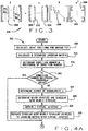
- a flow diagram of a method of operating the machine 24 in accordance with one implementation of the disclosure is indicated generally in Figures 4A and 4B by reference number 300.
- operation 308 kinematic joint positions for moving the tip portion 116 along a prescribed path are calculated.
- operation 312 a manipulator Jacobian J corresponding to the calculated joint 112 positions is calculated and then decomposed using SVD.
- operation 316 a reciprocal of a condition number is determined.
- the condition number reciprocal is compared to a predefined threshold value, e.g., 0.001. If the condition number reciprocal is greater than the threshold value, then it is assumed that the linkage 100 is not approaching any singularities, and control passes to operation 340.
- a predefined threshold value e.g., 0.001. If the condition number reciprocal is greater than the threshold value, then it is assumed that the linkage 100 is not approaching any singularities, and control passes to operation 340.
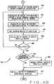
- a degree n of the singularity is determined in the following manner.
- n "virtual joint(s)" are obtained by taking the last n left singular vector(s) 208 and multiplying them by the largest singular value 236.
- the column(s) 204 of J associated with the joint(s) 112 determined in operation 328 are replaced with the "virtual joint(s)" obtained in operation 332.
- a nominal inverse kinematics calculation is used to obtain an initial link position vector Q i .
- an as-built forward kinematics calculation and the link position vector Q i are used to obtain an actual tip position vector X.
- a ⁇ X vector is calculated, indicating a difference between a desired tip position vector and an actual tip position vector.
- a ⁇ Q vector is calculated using the Jacobian matrix obtained in operation 312 (and as the Jacobian matrix may have been modified in operation 336).
- the ⁇ Q vector calculated in operation 352 and the link position vector Q i are used to obtain a new link position vector Q i+1 .
- convergence is tested by comparing an absolute difference between vectors Q i+1 and Q i to a predetermined convergence criterion ⁇ . If convergence has not yet been reached, the vector Q i+1 is used to update the vector Q i and control returns to operation 344.
- convergence is reached in operation 360, it then is determined in operation 364 whether the condition number reciprocal was less than the threshold value, that is, whether the linkage is approaching singularity.
- value(s) representing the "virtual joint(s)" are removed from the vector Q i+1 , which then is used in operation 372 to compensate the non-singular joints 112. Because SVD is performed only once for each point and is not part of the iterative solution process, the foregoing methods and systems are less computationally expensive than linear quadratic regulation (LQR) or damped least squares.
- LQR linear quadratic regulation
- left singular vectors provide ideal "virtual joint(s)", in that they move the linkage in exactly the singular direction(s), regardless of the position or complexity of the machine.
- Another advantage is that by scaling the "virtual joint(s)" by the largest singular value, the resulting condition of the new manipulator Jacobian is optimized, thereby assuring a stable, rapidly converging solution, e.g ., in operations 340 through 360 of the foregoing method 300.
- implementations of the foregoing method require no a priori knowledge of the locations of singularities for the machine, so the same algorithm can be used on a variety of machines without change.
- Implementations of the present disclosure provide a means of improving the positioning accuracy of automation equipment that works near its singularity. Where accuracy can be improved, costs of acquisition of new capital equipment, and maintenance costs for existing equipment, can be lowered. Furthermore, various implementations of the present disclosure can provide a single method that works on several different machine geometries, thereby reducing a need for software development and maintenance to deal with new machine geometries.
- Calibrated machine tools can be provided which are capable of producing more accurate work. Thus higher precision parts can be made with less waste material. When implemented in connection with aircraft production, the production of higher-precision parts can result in reduced weight and improved performance of aircraft. Implementations of the disclosure can result in reduced set-up time and more productive use of machine tools, thereby reducing the cost of machining.
Landscapes
- Engineering & Computer Science (AREA)
- Physics & Mathematics (AREA)
- Mathematical Physics (AREA)
- Automation & Control Theory (AREA)
- Robotics (AREA)
- Mechanical Engineering (AREA)
- Numerical Control (AREA)
- Manipulator (AREA)
Applications Claiming Priority (2)
| Application Number | Priority Date | Filing Date | Title |
|---|---|---|---|
| US11/514,072 US8010235B2 (en) | 2005-05-31 | 2006-08-31 | Approaching and compensating for machine kinematic singularities |
| PCT/US2007/018820 WO2008027334A2 (en) | 2006-08-31 | 2007-08-27 | Approaching and compensating for machine kinematic singularities |
Publications (2)
| Publication Number | Publication Date |
|---|---|
| EP2073959A2 EP2073959A2 (en) | 2009-07-01 |
| EP2073959B1 true EP2073959B1 (en) | 2018-01-10 |
Family
ID=39136516
Family Applications (1)
| Application Number | Title | Priority Date | Filing Date |
|---|---|---|---|
| EP07837375.0A Not-in-force EP2073959B1 (en) | 2006-08-31 | 2007-08-27 | Approaching and compensating for machine kinematic singularities |
Country Status (5)
| Country | Link |
|---|---|
| US (1) | US8010235B2 (enExample) |
| EP (1) | EP2073959B1 (enExample) |
| JP (1) | JP5393461B2 (enExample) |
| CN (1) | CN101505925B (enExample) |
| WO (1) | WO2008027334A2 (enExample) |
Families Citing this family (13)
| Publication number | Priority date | Publication date | Assignee | Title |
|---|---|---|---|---|
| JP4692488B2 (ja) * | 2005-12-26 | 2011-06-01 | 三菱電機株式会社 | 数値制御装置及び数値制御工作機械 |
| JP2008073830A (ja) * | 2006-09-25 | 2008-04-03 | Fanuc Ltd | ロボット制御装置 |
| FR2960074B1 (fr) * | 2010-05-14 | 2012-06-15 | Staubli Sa Ets | Procede de commande d'une cellule de travail automatisee |
| WO2011152790A1 (en) | 2010-06-03 | 2011-12-08 | Delaval Holding Ab | A milking robot, and a milking arrangement |
| DE102010032917A1 (de) * | 2010-07-30 | 2012-04-19 | Brötje-Automation GmbH | Verfahren zur Offline-Programmierung eines NC-gesteuerten Manipulators |
| US8532825B1 (en) * | 2010-08-25 | 2013-09-10 | The Boeing Company | Software compensation for kinematically singular machines |
| CN104965517B (zh) * | 2015-07-07 | 2018-01-26 | 张耀伦 | 一种机器人笛卡尔空间轨迹的规划方法 |
| CN105415363B (zh) * | 2015-12-23 | 2017-11-17 | 珠海格力电器股份有限公司 | 机器人奇异点处理方法 |
| US10065311B1 (en) * | 2016-06-08 | 2018-09-04 | X Development Llc | Singularity handling for robot jogging |
| JP7222898B2 (ja) * | 2017-06-12 | 2023-02-15 | ジーメンス インダストリー ソフトウェア リミテッド | ロボット製造での所定のターゲットへの到達をロボットにティーチングするための方法およびシステム |
| CN113263496B (zh) * | 2021-04-01 | 2022-09-23 | 北京无线电测量研究所 | 一种六自由度机械臂优化路径的方法和计算机设备 |
| CN114549352B (zh) * | 2022-02-21 | 2025-04-18 | 中国第一汽车股份有限公司 | 图像处理方法、装置、电子设备和存储介质 |
| WO2025053285A1 (ja) * | 2023-09-08 | 2025-03-13 | 技術研究組合 産業用ロボット次世代基礎技術研究機構 | プログラム、記憶媒体、情報処理装置、システム及びロボットの動作を制御する方法 |
Family Cites Families (18)
| Publication number | Priority date | Publication date | Assignee | Title |
|---|---|---|---|---|
| US4680519A (en) * | 1985-09-23 | 1987-07-14 | General Electric Co. | Recursive methods for world-to-joint transformation for a robot manipulator |
| US4937759A (en) * | 1986-02-18 | 1990-06-26 | Robotics Research Corporation | Industrial robot with controller |
| US5038089A (en) * | 1988-03-23 | 1991-08-06 | The United States Of America As Represented By The Administrator Of The National Aeronautics And Space Administration | Synchronized computational architecture for generalized bilateral control of robot arms |
| US4967126A (en) * | 1990-01-30 | 1990-10-30 | Ford Aerospace Corporation | Method of controlling a seven degree of freedom manipulator arm |
| SE9400579L (sv) * | 1994-02-21 | 1995-08-22 | Asea Brown Boveri | Förfarande för att styra en industrirobots rörelse i och i närheten av singulariteter |
| US5793795A (en) * | 1996-12-04 | 1998-08-11 | Motorola, Inc. | Method for correcting errors from a jamming signal in a frequency hopped spread spectrum communication system |
| JPH10329066A (ja) * | 1997-05-26 | 1998-12-15 | Mitsubishi Heavy Ind Ltd | 冗長マニピュレータの特異姿勢検知方法および特異姿勢回避方法 |
| US6208949B1 (en) * | 1998-07-01 | 2001-03-27 | Adaptive Audio, Inc. | Method and apparatus for dynamical system analysis |
| US6493608B1 (en) * | 1999-04-07 | 2002-12-10 | Intuitive Surgical, Inc. | Aspects of a control system of a minimally invasive surgical apparatus |
| US8004229B2 (en) * | 2005-05-19 | 2011-08-23 | Intuitive Surgical Operations, Inc. | Software center and highly configurable robotic systems for surgery and other uses |
| US6847925B2 (en) * | 2000-06-21 | 2005-01-25 | Hrl Laboratories, Llc | Method and apparatus for modeling three-dimensional electromagnetic scattering from arbitrarily shaped three-dimensional objects |
| US6603281B2 (en) * | 2000-10-16 | 2003-08-05 | Xerox Corporation | High mechanical advantage ratcheting apparatus |
| US6845295B2 (en) * | 2002-03-07 | 2005-01-18 | Fanuc Robotics America, Inc. | Method of controlling a robot through a singularity |
| JP3997405B2 (ja) * | 2002-07-26 | 2007-10-24 | 株式会社安川電機 | 移動マニピュレータの制御装置および移動マニピュレータ |
| US6952657B2 (en) * | 2003-09-10 | 2005-10-04 | Peak Sensor Systems Llc | Industrial process fault detection using principal component analysis |
| GB0507618D0 (en) * | 2005-04-15 | 2005-05-25 | Lms Internat Nv | Method and system for dynamic analysis of complex systems |
| US7571027B2 (en) | 2005-05-31 | 2009-08-04 | The Boeing Company | Kinematic singular point compensation systems and methods |
| US8725283B2 (en) * | 2006-08-04 | 2014-05-13 | Hurco Companies, Inc. | Generalized kinematics system |
-
2006
- 2006-08-31 US US11/514,072 patent/US8010235B2/en not_active Expired - Fee Related
-
2007
- 2007-08-27 CN CN2007800306231A patent/CN101505925B/zh not_active Expired - Fee Related
- 2007-08-27 EP EP07837375.0A patent/EP2073959B1/en not_active Not-in-force
- 2007-08-27 JP JP2009526668A patent/JP5393461B2/ja not_active Expired - Fee Related
- 2007-08-27 WO PCT/US2007/018820 patent/WO2008027334A2/en not_active Ceased
Also Published As
| Publication number | Publication date |
|---|---|
| CN101505925A (zh) | 2009-08-12 |
| US8010235B2 (en) | 2011-08-30 |
| JP2010502454A (ja) | 2010-01-28 |
| WO2008027334A2 (en) | 2008-03-06 |
| JP5393461B2 (ja) | 2014-01-22 |
| CN101505925B (zh) | 2012-07-18 |
| US20070112468A1 (en) | 2007-05-17 |
| EP2073959A2 (en) | 2009-07-01 |
| WO2008027334A3 (en) | 2008-10-02 |
Similar Documents
| Publication | Publication Date | Title |
|---|---|---|
| EP2073959B1 (en) | Approaching and compensating for machine kinematic singularities | |
| Zhu et al. | An off-line programming system for robotic drilling in aerospace manufacturing | |
| Peng et al. | Smoothness-oriented path optimization for robotic milling processes | |
| Abbaszadeh-Mir et al. | Theory and simulation for the identification of the link geometric errors for a five-axis machine tool using a telescoping magnetic ball-bar | |
| Abele et al. | Modeling and identification of an industrial robot for machining applications | |
| US8121733B2 (en) | Kinematic singular point compensation systems | |
| Lee et al. | A robust trajectory tracking control of a polishing robot system based on CAM data | |
| Celikag et al. | Cartesian stiffness optimization for serial arm robots | |
| Omodei et al. | Calibration of a measuring robot: Experimental results on a 5 DOF structure | |
| Gao et al. | Robotic milling stability optimization based on robot functional redundancy | |
| Jiao et al. | Variable parameters stiffness identification and modeling for positional compensation of industrial robots | |
| Lee | Apply force/torque sensors to robotic applications | |
| Çakır et al. | Path planning for industrial robot milling applications | |
| Zhu et al. | Inverse kinematics solution of a new circumferential drilling machine for aircraft assembly | |
| CN118438449B (zh) | 适用于移动工业机器加工大型回转类构件的站位优化方法 | |
| Zhao et al. | An efficient error prediction and compensation method for coordinated five-axis machine tools under variable temperature | |
| Tian et al. | Research on robotic automatic machining for welding groove of complex integral impeller | |
| Tajima et al. | Posture optimization in robot machining with kinematic redundancy for high-precision positioning | |
| Glavonjic et al. | Parallel structured milling machines with long X travel | |
| CN112775974B (zh) | 工业机器人铣削过程中的关节刚度辨识方法 | |
| Fraczek et al. | Calibration of multi-robot system without and under load using electronic theodolites | |
| Mbarek et al. | Positioning system for the aircraft structural assembly | |
| JP2021186929A (ja) | 多軸ロボットの制御方法 | |
| Kalsoom et al. | Design of a Digital Twin Based Feedback Controller for a Parallel Mechanism Based Six Degree of Freedom Machining Bed | |
| Patel et al. | Improving the absolute accuracy by online interpolation technique of industrial robots |
Legal Events
| Date | Code | Title | Description |
|---|---|---|---|
| PUAI | Public reference made under article 153(3) epc to a published international application that has entered the european phase |
Free format text: ORIGINAL CODE: 0009012 |
|
| 17P | Request for examination filed |
Effective date: 20090331 |
|
| AK | Designated contracting states |
Kind code of ref document: A2 Designated state(s): AT BE BG CH CY CZ DE DK EE ES FI FR GB GR HU IE IS IT LI LT LU LV MC MT NL PL PT RO SE SI SK TR |
|
| DAX | Request for extension of the european patent (deleted) | ||
| GRAP | Despatch of communication of intention to grant a patent |
Free format text: ORIGINAL CODE: EPIDOSNIGR1 |
|
| INTG | Intention to grant announced |
Effective date: 20170801 |
|
| GRAS | Grant fee paid |
Free format text: ORIGINAL CODE: EPIDOSNIGR3 |
|
| GRAA | (expected) grant |
Free format text: ORIGINAL CODE: 0009210 |
|
| AK | Designated contracting states |
Kind code of ref document: B1 Designated state(s): AT BE BG CH CY CZ DE DK EE ES FI FR GB GR HU IE IS IT LI LT LU LV MC MT NL PL PT RO SE SI SK TR |
|
| REG | Reference to a national code |
Ref country code: GB Ref legal event code: FG4D |
|
| REG | Reference to a national code |
Ref country code: CH Ref legal event code: EP Ref country code: AT Ref legal event code: REF Ref document number: 961876 Country of ref document: AT Kind code of ref document: T Effective date: 20180115 |
|
| REG | Reference to a national code |
Ref country code: IE Ref legal event code: FG4D |
|
| REG | Reference to a national code |
Ref country code: DE Ref legal event code: R096 Ref document number: 602007053680 Country of ref document: DE |
|
| REG | Reference to a national code |
Ref country code: NL Ref legal event code: MP Effective date: 20180110 |
|
| REG | Reference to a national code |
Ref country code: AT Ref legal event code: MK05 Ref document number: 961876 Country of ref document: AT Kind code of ref document: T Effective date: 20180110 |
|
| PG25 | Lapsed in a contracting state [announced via postgrant information from national office to epo] |
Ref country code: NL Free format text: LAPSE BECAUSE OF FAILURE TO SUBMIT A TRANSLATION OF THE DESCRIPTION OR TO PAY THE FEE WITHIN THE PRESCRIBED TIME-LIMIT Effective date: 20180110 |
|
| PG25 | Lapsed in a contracting state [announced via postgrant information from national office to epo] |
Ref country code: ES Free format text: LAPSE BECAUSE OF FAILURE TO SUBMIT A TRANSLATION OF THE DESCRIPTION OR TO PAY THE FEE WITHIN THE PRESCRIBED TIME-LIMIT Effective date: 20180110 Ref country code: LT Free format text: LAPSE BECAUSE OF FAILURE TO SUBMIT A TRANSLATION OF THE DESCRIPTION OR TO PAY THE FEE WITHIN THE PRESCRIBED TIME-LIMIT Effective date: 20180110 Ref country code: CY Free format text: LAPSE BECAUSE OF FAILURE TO SUBMIT A TRANSLATION OF THE DESCRIPTION OR TO PAY THE FEE WITHIN THE PRESCRIBED TIME-LIMIT Effective date: 20180110 Ref country code: FI Free format text: LAPSE BECAUSE OF FAILURE TO SUBMIT A TRANSLATION OF THE DESCRIPTION OR TO PAY THE FEE WITHIN THE PRESCRIBED TIME-LIMIT Effective date: 20180110 |
|
| REG | Reference to a national code |
Ref country code: FR Ref legal event code: PLFP Year of fee payment: 12 |
|
| PG25 | Lapsed in a contracting state [announced via postgrant information from national office to epo] |
Ref country code: PL Free format text: LAPSE BECAUSE OF FAILURE TO SUBMIT A TRANSLATION OF THE DESCRIPTION OR TO PAY THE FEE WITHIN THE PRESCRIBED TIME-LIMIT Effective date: 20180110 Ref country code: AT Free format text: LAPSE BECAUSE OF FAILURE TO SUBMIT A TRANSLATION OF THE DESCRIPTION OR TO PAY THE FEE WITHIN THE PRESCRIBED TIME-LIMIT Effective date: 20180110 Ref country code: GR Free format text: LAPSE BECAUSE OF FAILURE TO SUBMIT A TRANSLATION OF THE DESCRIPTION OR TO PAY THE FEE WITHIN THE PRESCRIBED TIME-LIMIT Effective date: 20180411 Ref country code: BG Free format text: LAPSE BECAUSE OF FAILURE TO SUBMIT A TRANSLATION OF THE DESCRIPTION OR TO PAY THE FEE WITHIN THE PRESCRIBED TIME-LIMIT Effective date: 20180410 Ref country code: LV Free format text: LAPSE BECAUSE OF FAILURE TO SUBMIT A TRANSLATION OF THE DESCRIPTION OR TO PAY THE FEE WITHIN THE PRESCRIBED TIME-LIMIT Effective date: 20180110 Ref country code: IS Free format text: LAPSE BECAUSE OF FAILURE TO SUBMIT A TRANSLATION OF THE DESCRIPTION OR TO PAY THE FEE WITHIN THE PRESCRIBED TIME-LIMIT Effective date: 20180510 Ref country code: SE Free format text: LAPSE BECAUSE OF FAILURE TO SUBMIT A TRANSLATION OF THE DESCRIPTION OR TO PAY THE FEE WITHIN THE PRESCRIBED TIME-LIMIT Effective date: 20180110 |
|
| REG | Reference to a national code |
Ref country code: DE Ref legal event code: R097 Ref document number: 602007053680 Country of ref document: DE |
|
| PG25 | Lapsed in a contracting state [announced via postgrant information from national office to epo] |
Ref country code: RO Free format text: LAPSE BECAUSE OF FAILURE TO SUBMIT A TRANSLATION OF THE DESCRIPTION OR TO PAY THE FEE WITHIN THE PRESCRIBED TIME-LIMIT Effective date: 20180110 Ref country code: IT Free format text: LAPSE BECAUSE OF FAILURE TO SUBMIT A TRANSLATION OF THE DESCRIPTION OR TO PAY THE FEE WITHIN THE PRESCRIBED TIME-LIMIT Effective date: 20180110 Ref country code: EE Free format text: LAPSE BECAUSE OF FAILURE TO SUBMIT A TRANSLATION OF THE DESCRIPTION OR TO PAY THE FEE WITHIN THE PRESCRIBED TIME-LIMIT Effective date: 20180110 |
|
| PLBE | No opposition filed within time limit |
Free format text: ORIGINAL CODE: 0009261 |
|
| STAA | Information on the status of an ep patent application or granted ep patent |
Free format text: STATUS: NO OPPOSITION FILED WITHIN TIME LIMIT |
|
| PG25 | Lapsed in a contracting state [announced via postgrant information from national office to epo] |
Ref country code: DK Free format text: LAPSE BECAUSE OF FAILURE TO SUBMIT A TRANSLATION OF THE DESCRIPTION OR TO PAY THE FEE WITHIN THE PRESCRIBED TIME-LIMIT Effective date: 20180110 Ref country code: SK Free format text: LAPSE BECAUSE OF FAILURE TO SUBMIT A TRANSLATION OF THE DESCRIPTION OR TO PAY THE FEE WITHIN THE PRESCRIBED TIME-LIMIT Effective date: 20180110 Ref country code: CZ Free format text: LAPSE BECAUSE OF FAILURE TO SUBMIT A TRANSLATION OF THE DESCRIPTION OR TO PAY THE FEE WITHIN THE PRESCRIBED TIME-LIMIT Effective date: 20180110 |
|
| 26N | No opposition filed |
Effective date: 20181011 |
|
| PG25 | Lapsed in a contracting state [announced via postgrant information from national office to epo] |
Ref country code: SI Free format text: LAPSE BECAUSE OF FAILURE TO SUBMIT A TRANSLATION OF THE DESCRIPTION OR TO PAY THE FEE WITHIN THE PRESCRIBED TIME-LIMIT Effective date: 20180110 |
|
| PG25 | Lapsed in a contracting state [announced via postgrant information from national office to epo] |
Ref country code: MC Free format text: LAPSE BECAUSE OF FAILURE TO SUBMIT A TRANSLATION OF THE DESCRIPTION OR TO PAY THE FEE WITHIN THE PRESCRIBED TIME-LIMIT Effective date: 20180110 |
|
| REG | Reference to a national code |
Ref country code: CH Ref legal event code: PL |
|
| PG25 | Lapsed in a contracting state [announced via postgrant information from national office to epo] |
Ref country code: CH Free format text: LAPSE BECAUSE OF NON-PAYMENT OF DUE FEES Effective date: 20180831 Ref country code: LI Free format text: LAPSE BECAUSE OF NON-PAYMENT OF DUE FEES Effective date: 20180831 Ref country code: LU Free format text: LAPSE BECAUSE OF NON-PAYMENT OF DUE FEES Effective date: 20180827 |
|
| REG | Reference to a national code |
Ref country code: BE Ref legal event code: MM Effective date: 20180831 |
|
| PG25 | Lapsed in a contracting state [announced via postgrant information from national office to epo] |
Ref country code: BE Free format text: LAPSE BECAUSE OF NON-PAYMENT OF DUE FEES Effective date: 20180831 |
|
| PGFP | Annual fee paid to national office [announced via postgrant information from national office to epo] |
Ref country code: DE Payment date: 20190828 Year of fee payment: 13 Ref country code: FR Payment date: 20190826 Year of fee payment: 13 |
|
| PGFP | Annual fee paid to national office [announced via postgrant information from national office to epo] |
Ref country code: GB Payment date: 20190827 Year of fee payment: 13 |
|
| PG25 | Lapsed in a contracting state [announced via postgrant information from national office to epo] |
Ref country code: MT Free format text: LAPSE BECAUSE OF NON-PAYMENT OF DUE FEES Effective date: 20180827 |
|
| PG25 | Lapsed in a contracting state [announced via postgrant information from national office to epo] |
Ref country code: TR Free format text: LAPSE BECAUSE OF FAILURE TO SUBMIT A TRANSLATION OF THE DESCRIPTION OR TO PAY THE FEE WITHIN THE PRESCRIBED TIME-LIMIT Effective date: 20180110 |
|
| PG25 | Lapsed in a contracting state [announced via postgrant information from national office to epo] |
Ref country code: PT Free format text: LAPSE BECAUSE OF FAILURE TO SUBMIT A TRANSLATION OF THE DESCRIPTION OR TO PAY THE FEE WITHIN THE PRESCRIBED TIME-LIMIT Effective date: 20180110 Ref country code: HU Free format text: LAPSE BECAUSE OF FAILURE TO SUBMIT A TRANSLATION OF THE DESCRIPTION OR TO PAY THE FEE WITHIN THE PRESCRIBED TIME-LIMIT; INVALID AB INITIO Effective date: 20070827 |
|
| PG25 | Lapsed in a contracting state [announced via postgrant information from national office to epo] |
Ref country code: IE Free format text: LAPSE BECAUSE OF NON-PAYMENT OF DUE FEES Effective date: 20180827 |
|
| REG | Reference to a national code |
Ref country code: DE Ref legal event code: R119 Ref document number: 602007053680 Country of ref document: DE |
|
| GBPC | Gb: european patent ceased through non-payment of renewal fee |
Effective date: 20200827 |
|
| PG25 | Lapsed in a contracting state [announced via postgrant information from national office to epo] |
Ref country code: DE Free format text: LAPSE BECAUSE OF NON-PAYMENT OF DUE FEES Effective date: 20210302 Ref country code: FR Free format text: LAPSE BECAUSE OF NON-PAYMENT OF DUE FEES Effective date: 20200831 |
|
| PG25 | Lapsed in a contracting state [announced via postgrant information from national office to epo] |
Ref country code: GB Free format text: LAPSE BECAUSE OF NON-PAYMENT OF DUE FEES Effective date: 20200827 |