EP2072831A2 - Vacuum pump - Google Patents
Vacuum pump Download PDFInfo
- Publication number
- EP2072831A2 EP2072831A2 EP08170560A EP08170560A EP2072831A2 EP 2072831 A2 EP2072831 A2 EP 2072831A2 EP 08170560 A EP08170560 A EP 08170560A EP 08170560 A EP08170560 A EP 08170560A EP 2072831 A2 EP2072831 A2 EP 2072831A2
- Authority
- EP
- European Patent Office
- Prior art keywords
- stator
- vacuum pump
- rotor
- motor
- pumping mechanism
- Prior art date
- Legal status (The legal status is an assumption and is not a legal conclusion. Google has not performed a legal analysis and makes no representation as to the accuracy of the status listed.)
- Granted
Links
- 238000005086 pumping Methods 0.000 claims abstract description 36
- 230000007246 mechanism Effects 0.000 claims abstract description 34
- 230000004907 flux Effects 0.000 claims description 9
- 239000000463 material Substances 0.000 claims description 8
- 230000035699 permeability Effects 0.000 claims description 6
- 230000001419 dependent effect Effects 0.000 claims description 3
- 229910000838 Al alloy Inorganic materials 0.000 claims description 2
- 238000003384 imaging method Methods 0.000 claims description 2
- 230000003287 optical effect Effects 0.000 claims description 2
- 229910000831 Steel Inorganic materials 0.000 claims 1
- 238000005259 measurement Methods 0.000 claims 1
- 239000010959 steel Substances 0.000 claims 1
- 238000004804 winding Methods 0.000 description 31
- XEEYBQQBJWHFJM-UHFFFAOYSA-N iron Substances [Fe] XEEYBQQBJWHFJM-UHFFFAOYSA-N 0.000 description 13
- 229910052742 iron Inorganic materials 0.000 description 8
- 238000004519 manufacturing process Methods 0.000 description 5
- 230000005355 Hall effect Effects 0.000 description 4
- 230000004323 axial length Effects 0.000 description 4
- 230000002093 peripheral effect Effects 0.000 description 4
- RYGMFSIKBFXOCR-UHFFFAOYSA-N Copper Chemical compound [Cu] RYGMFSIKBFXOCR-UHFFFAOYSA-N 0.000 description 3
- 239000010949 copper Substances 0.000 description 3
- 229910052802 copper Inorganic materials 0.000 description 3
- 230000000694 effects Effects 0.000 description 3
- 238000011065 in-situ storage Methods 0.000 description 3
- 230000008901 benefit Effects 0.000 description 2
- 230000003247 decreasing effect Effects 0.000 description 2
- 238000010586 diagram Methods 0.000 description 2
- 238000000034 method Methods 0.000 description 2
- 230000009467 reduction Effects 0.000 description 2
- 229910001209 Low-carbon steel Inorganic materials 0.000 description 1
- 239000004411 aluminium Substances 0.000 description 1
- XAGFODPZIPBFFR-UHFFFAOYSA-N aluminium Chemical compound [Al] XAGFODPZIPBFFR-UHFFFAOYSA-N 0.000 description 1
- 229910052782 aluminium Inorganic materials 0.000 description 1
- 230000009286 beneficial effect Effects 0.000 description 1
- 239000002131 composite material Substances 0.000 description 1
- 230000006835 compression Effects 0.000 description 1
- 238000007906 compression Methods 0.000 description 1
- 239000004020 conductor Substances 0.000 description 1
- 238000010276 construction Methods 0.000 description 1
- 238000009826 distribution Methods 0.000 description 1
- 230000010354 integration Effects 0.000 description 1
- 238000010884 ion-beam technique Methods 0.000 description 1
- 238000001459 lithography Methods 0.000 description 1
- 239000000843 powder Substances 0.000 description 1
- 238000004663 powder metallurgy Methods 0.000 description 1
- 230000008569 process Effects 0.000 description 1
Images


Classifications
-
- F—MECHANICAL ENGINEERING; LIGHTING; HEATING; WEAPONS; BLASTING
- F04—POSITIVE - DISPLACEMENT MACHINES FOR LIQUIDS; PUMPS FOR LIQUIDS OR ELASTIC FLUIDS
- F04D—NON-POSITIVE-DISPLACEMENT PUMPS
- F04D19/00—Axial-flow pumps
- F04D19/02—Multi-stage pumps
- F04D19/04—Multi-stage pumps specially adapted to the production of a high vacuum, e.g. molecular pumps
- F04D19/042—Turbomolecular vacuum pumps
-
- F—MECHANICAL ENGINEERING; LIGHTING; HEATING; WEAPONS; BLASTING
- F04—POSITIVE - DISPLACEMENT MACHINES FOR LIQUIDS; PUMPS FOR LIQUIDS OR ELASTIC FLUIDS
- F04D—NON-POSITIVE-DISPLACEMENT PUMPS
- F04D25/00—Pumping installations or systems
- F04D25/02—Units comprising pumps and their driving means
- F04D25/06—Units comprising pumps and their driving means the pump being electrically driven
- F04D25/0606—Units comprising pumps and their driving means the pump being electrically driven the electric motor being specially adapted for integration in the pump
-
- F—MECHANICAL ENGINEERING; LIGHTING; HEATING; WEAPONS; BLASTING
- F04—POSITIVE - DISPLACEMENT MACHINES FOR LIQUIDS; PUMPS FOR LIQUIDS OR ELASTIC FLUIDS
- F04D—NON-POSITIVE-DISPLACEMENT PUMPS
- F04D27/00—Control, e.g. regulation, of pumps, pumping installations or pumping systems specially adapted for elastic fluids
- F04D27/001—Testing thereof; Determination or simulation of flow characteristics; Stall or surge detection, e.g. condition monitoring
-
- F—MECHANICAL ENGINEERING; LIGHTING; HEATING; WEAPONS; BLASTING
- F04—POSITIVE - DISPLACEMENT MACHINES FOR LIQUIDS; PUMPS FOR LIQUIDS OR ELASTIC FLUIDS
- F04D—NON-POSITIVE-DISPLACEMENT PUMPS
- F04D27/00—Control, e.g. regulation, of pumps, pumping installations or pumping systems specially adapted for elastic fluids
- F04D27/02—Surge control
- F04D27/0261—Surge control by varying driving speed
-
- H—ELECTRICITY
- H02—GENERATION; CONVERSION OR DISTRIBUTION OF ELECTRIC POWER
- H02K—DYNAMO-ELECTRIC MACHINES
- H02K29/00—Motors or generators having non-mechanical commutating devices, e.g. discharge tubes or semiconductor devices
- H02K29/06—Motors or generators having non-mechanical commutating devices, e.g. discharge tubes or semiconductor devices with position sensing devices
- H02K29/12—Motors or generators having non-mechanical commutating devices, e.g. discharge tubes or semiconductor devices with position sensing devices using detecting coils using the machine windings as detecting coil
-
- H—ELECTRICITY
- H02—GENERATION; CONVERSION OR DISTRIBUTION OF ELECTRIC POWER
- H02P—CONTROL OR REGULATION OF ELECTRIC MOTORS, ELECTRIC GENERATORS OR DYNAMO-ELECTRIC CONVERTERS; CONTROLLING TRANSFORMERS, REACTORS OR CHOKE COILS
- H02P25/00—Arrangements or methods for the control of AC motors characterised by the kind of AC motor or by structural details
- H02P25/16—Arrangements or methods for the control of AC motors characterised by the kind of AC motor or by structural details characterised by the circuit arrangement or by the kind of wiring
-
- H—ELECTRICITY
- H02—GENERATION; CONVERSION OR DISTRIBUTION OF ELECTRIC POWER
- H02P—CONTROL OR REGULATION OF ELECTRIC MOTORS, ELECTRIC GENERATORS OR DYNAMO-ELECTRIC CONVERTERS; CONTROLLING TRANSFORMERS, REACTORS OR CHOKE COILS
- H02P6/00—Arrangements for controlling synchronous motors or other dynamo-electric motors using electronic commutation dependent on the rotor position; Electronic commutators therefor
- H02P6/14—Electronic commutators
- H02P6/16—Circuit arrangements for detecting position
- H02P6/18—Circuit arrangements for detecting position without separate position detecting elements
- H02P6/182—Circuit arrangements for detecting position without separate position detecting elements using back-emf in windings
-
- H—ELECTRICITY
- H02—GENERATION; CONVERSION OR DISTRIBUTION OF ELECTRIC POWER
- H02K—DYNAMO-ELECTRIC MACHINES
- H02K3/00—Details of windings
- H02K3/04—Windings characterised by the conductor shape, form or construction, e.g. with bar conductors
- H02K3/28—Layout of windings or of connections between windings
-
- Y—GENERAL TAGGING OF NEW TECHNOLOGICAL DEVELOPMENTS; GENERAL TAGGING OF CROSS-SECTIONAL TECHNOLOGIES SPANNING OVER SEVERAL SECTIONS OF THE IPC; TECHNICAL SUBJECTS COVERED BY FORMER USPC CROSS-REFERENCE ART COLLECTIONS [XRACs] AND DIGESTS
- Y02—TECHNOLOGIES OR APPLICATIONS FOR MITIGATION OR ADAPTATION AGAINST CLIMATE CHANGE
- Y02B—CLIMATE CHANGE MITIGATION TECHNOLOGIES RELATED TO BUILDINGS, e.g. HOUSING, HOUSE APPLIANCES OR RELATED END-USER APPLICATIONS
- Y02B30/00—Energy efficient heating, ventilation or air conditioning [HVAC]
- Y02B30/70—Efficient control or regulation technologies, e.g. for control of refrigerant flow, motor or heating
Definitions
- the invention relates to a vacuum pump.
- a Holweck pumping mechanism comprises at least one cylinder 80 rotatable about an axis 82.
- a space is provided radially inward of the cylinder in which a motor 84 may be positioned provided that the outer diameter of the motor is constrained so that it fits within the space.
- a Gaede or Siegbahn pumping mechanism comprises at least one disk 86 rotatable about the axis 82.
- a motor 88 for such mechanisms is positioned on one axial side of the mechanism and therefore, it is desirable to limit the axial length of the motor in order to conserve space in the pump.
- a radial dimension of a motor for a Gaede or Siegbahn mechanism is relatively less constrained.
- Motors for vacuum pumps are either constrained in axial or radial dimension according to the type of pumping mechanism with which they are used, and therefore it is necessary to provide two different types of motor.
- a motor of a compact size is desirable for use with both Holweck type and Siegbahn and Gaede types of vacuum pumping mechanisms.
- Vacuum pumps may be used with scientific or manufacturing equipment which is sensitive to magnetic interference. Such equipment includes electron microscopes, focused ion beam instruments and lithography equipment. Turbomolecular pumps of the types described above are often used to achieve the high vacuum typically required in such equipment.
- a Turbomolecular pump 90 is shown in Figure 10 . Such pumps are designed for high rotational speeds in the region of 36,000 to 90,000 rpm and may be driven by a permanent magnet brushless DC motor 92. Such motors have a two-pole configuration in order to minimise the commutation frequency and simplify the design of the drive electronics.
- Brushless DC motors generally comprise one or more hall effect sensors 94 for sensing rotation of a permanent magnet rotor 96.
- the rotor 96 extends axially beyond an end of the stator 98 so that the sensors can measure the rotation of the rotor.
- the extension of the rotor causes increased stray magnetic fields to leak out of the pump and interfere with scientific or manufacturing equipment, even though typically the extension may be only around 5mm. It is desirable to reduce magnetic interference from the motor.
- the invention provides a vacuum pump comprising a vacuum pumping mechanism rotatable by a shaft and a brushless motor for rotating said shaft, wherein said motor comprises: a permanent magnet rotor fixed relative to said shaft, said rotor having at least four poles; a stator fixed relative to a pump housing, said stator having non-overlapping stator coils; and motor control means for selective energisation of said stator coils dependent on a relative position of said rotor and said stator so that said rotor can be rotated relative to said stator.
- a vacuum pump 10 which comprises a vacuum pumping mechanism 12 mounted for rotation by a shaft 14 and a brushless motor 16 for rotating the shaft.
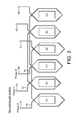
- the vacuum pumping mechanism 12 comprises a turbo pumping mechanism 18 comprising a plurality of pumping stages, and a molecular drag pumping mechanism 20 comprising at least one pumping stage.
- Shaft 14 is supported for rotation by bearings 22.
- the vacuum pumping mechanism may comprise any one or more types of turbomolecular pumping mechanisms, for instance and without limitation, turbo, Gaede, Siegbahn or Holweck type mechanisms. As shown in Figure 1 , turbo and Siegbahn mechanisms are shown.
- Vacuum pumping mechanisms require rotation at high speed, typically at speeds of at least 20,000 rpm and generally at speeds of between about 36,000 and 90,000 rpm. Such high speeds are necessary to achieve compression from pressures of about 1x10 -10 Torr at an inlet of the pump and 1 Torr at an outlet of the pump. Vacuum pumps are considered therefore to be very high speed pumps.
- the motor 16 comprises a permanent magnet rotor 24 fixed relative to the shaft 14.
- the rotor 24 has four poles as will be described in greater detail below with reference to Figure 2 . More than four poles may be adopted as required.
- the motor comprises a stator 26 fixed relative to a pump housing 28.
- the stator has non-overlapping stator coils, which are also described in greater detail below with reference to Figure 2 .
- a motor control means 30 is operable for commutation of the motor by selective energisation of the stator coils dependent on a relative position of the rotor 24 and the stator 26 so that the rotor can be rotated relative to the stator for driving the pumping mechanism 12.
- the motor control means 30 is described in greater detail below with reference to Figure 5 .
- the motor control means 30 is configured to control selective energisation of the stator coils without a sensor, such as a hall effect or other magnetic field based sensors. Accordingly, the rotor 24 is not required to extend beyond the stator 26 as shown in Figure 10 to allow such sensors to function. As a consequence, stray magnetic fields encountered with prior art brushless motors are reduced with the arrangement shown in Figure 1 and therefore, vacuum pump 10 is more suitable for use with scientific or manufacturing equipment which is sensitive to magnetic interference.
- the rotor 24 is generally cylindrical having a radially inner surface which is fixed to a radially outer surface of shaft 14 for rotation about an axis 32.
- the rotor has four generally equal arcuate segments or, if the rotor is of unitary construction, four generally equal arcuate rotor portions, which constitute four poles of the rotor.
- the north and south poles are arranged alternately around the rotor, each pole extending over no more than 90° about axis 32. Whilst four poles are shown in Figure 2 , more than four poles can be adopted as required.
- Stator 26 is fixed by suitable means relative to pump housing 28.
- the stator has a core with a generally annular peripheral portion, or back-iron, 34 from which six pole shoes 36 extend radially inwardly.
- the pole shoes are angularly spaced generally equally about the peripheral portion 34 at an angle of about 60°.
- the radially inner face of each shoe 36 is spaced from a radially outer surface of rotor 24 by an air-gap in which magnetic flux is controlled by operation of the stator in order to control rotation of the rotor.
- the embodiment shown comprises a three phase motor having four pole rotor and six stator shoes
- the motor may comprise any even number of poles equal to or greater than four (4, 6, 8, 10 etc).
- More or less than three phases may be provided as required, however at least three phases are preferred for providing smooth torque distribution.
- P is the number of poles and M is the number of phases
- the number of shoes must be equal to or greater than P/2 x M.
- the stator winding comprises three wires configured to form six non-overlapping stator coils 38.
- the six stator coils are wound about respective pole shoes 36, as indicated at A1, B1, C1, A2, B2, C2.
- a first wire 40 is connected between electrical contacts 41 and forms stator coils at A1 and A2.
- a second wire 42 is connected between electrical contacts 43 and forms stator coils at B1 and B2.
- a third wire 44 is connected between electrical contacts 45 and forms stator coils at C1 and C2.
- Electrical contacts 41, 43, 45 are connected to frequency converter 60 described hereinafter.
- each of the first, second and third wires extend over the axial end of stator core portion 34 between respective coils A1 and A2, B1 and B1, and C1 and C2.
- the axial length of the stator is determined by a length of peripheral portion 36 and an axial extent of the windings which protrude beyond each axial end face of portion 36. Additionally, wires 40, 42, 44 extend over the end face of the core and therefore may further extend the axial extent of the stator.
- Figure 3 shows the non-overlapping winding arrangement of Figure 2
- Figure 4 shows a prior art overlapping arrangement.
- the non-overlapping stator windings can be wound in-situ and occupy less space in an axial and/or circumferential direction of the motor as compared to overlapping windings.
- the space required around and at an axial end of each pole shoe is less for a non-overlapping winding since only one coil is wound around each shoe.
- an overlapping winding arrangement can not be wound in-situ but instead requires a relatively complicated and time consuming winding technique. If a non-overlapping winding arrangement is adopted as in the present invention it is further possible to provide a stator with a segmented stator core.
- each segment comprises one pole shoe and the winding can readily be made prior to integration of segments to form the stator. It is a further advantage in a segmented stator that the stator can be made from a non-sintered composite powder material using standard powder metallurgy processes.
- Each segment of such a stator can be moulded/cast such that the axial end of the pole shoe is spaced from an axial end of the back-iron (peripheral portion 34) to provide a space for the winding, so that when a winding is formed on the pole shoe the windings do not extend beyond either axial end of the back iron.
- non-overlapping windings have a relatively uncomplicated configuration which is more easily manufactured and allows a reduction in axial and/or radial extent of the stator compared to the prior art configuration shown in Figure 4 .
- the windings 102, 104, 106 are more difficult to manufacture and are not capable of being formed in-situ or in combination with a segmented stator.
- such windings occupy relatively more space around each of the pole shoes increasing a diameter of the motor and also such windings have a greater overhang in an axial direction relative to the back-iron increasing an axial length of the stator.
- Figure 5 shows the motor control means 30.
- the motor control means is operable to control energisation of the stator coils at A1 and A2, B1 and B2, and C1 and C2 to provide three phase commutation.
- the motor control means 30 determines a relative angular position of the rotor and the stator by measuring a voltage and current in the stator windings and controls energisation of the stator windings to provide correct commutation.
- EP0925641 , EP1189335 and EP1705792 each show control means for commutating a motor without the use of a sensor and the content of each of those applications is incorporated herein by reference.
- control means 30 comprises a frequency converter 60 for providing phased energisation of the stator windings 38.
- V voltage
- I current
- R the resistance
- N the number of turns
- A the cross-sectional area
- L the inductance
- B the magnetic flux density
- An angular position of the rotor can be determined according to the variation in flux and a position signal output to a control unit 64 for use in controlling the frequency converter 60 to achieve correct commutation.
- the pump housing 28 shown in Figure 1 is typically made from an electrically conductive material, for instance an aluminium alloy, an increase in the frequency of the alternating magnetic field generated results in an increase in the attenuation effect of the housing by eddy-current shielding. Accordingly, the adoption of a four pole motor in a vacuum pump renders the vacuum pump more suitable for use with sensitive equipment.
- T m of the pump housing is a measure of the distance through the housing over which the magnetic field is reduced by a ratio of "e" (approximately 2.72). Therefore, shielding is increased as the skin thickness is reduced.
- the skin thickness can be calculated according to the formula below.
- the skin thickness is relatively small and therefore the shielding effect is relatively large.
- the increased frequency of the four pole rotor further increases the shielding effect.
- Iron losses W FE can be approximated according to the formula below.
- a four pole motor requires higher frequency commutation, which will increase the iron losses in the stator.
- the copper losses are decreased by avoiding long end windings normally involved in an overlapping winding arrangement.
- the copper losses are decreased as the resistance of the winding is reduced as less wire is required to form the windings. This reduction in copper loss can be traded against a potential increase in stator iron loss to keep the total losses of the motor similar to the losses in a conventional two pole motor.
- Stray magnetic fields are also reduced as the flux in a four pole motor travels a quarter rather than half the motor, and hence extends less radially (lower magnitude of flux density in radial direction). Additionally, stray magnetic fields are additionally reduced as commutation of the motor is calculated as shown in Figure 5 , and therefore hall effect sensors are not required. As described above in relation to the prior art, the use of hall effect sensors necessitates an extension of the rotor beyond the stator and leads to increased stray magnetic fields.
- a sensor-less motor is advantageous as it renders the motor more suitable for use with sensitive equipment, such as equipment for one of metrology, imaging or pattern-making.
- an optical sensor may be used to determine rotation of the rotor and to transmit the determination to the motor control means for control of commutation.
- motor 16 is reduced in both radial and axial dimension as compared to prior art motors and therefore as shown in Figures 6 and 7 as compared with Figures 8 and 9 , motor 16 can be used both with Holweck type vacuum pumping mechanisms and with Gaede and Siegbahn type vacuum pumping mechanisms. Therefore it is not necessary to produce multiple different types of motors for different types of pumping mechanisms and thus manufacturing costs can be reduced. It is a further advantage that the reduced dimensions of motor 16 allow a more compact vacuum pump.
Abstract
Description
- The invention relates to a vacuum pump.
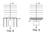
- Turbo, Siegbahn, Holweck and Gaede are known vacuum pumping mechanisms. Such mechanisms are driven by a motor which causes rotation about an axis. It is often desirable to provide a vacuum pump which is compact in size and in order to achieve a compact design, the motor is positioned differently relative to the various different types of pumping mechanisms in order to increase the efficient use of space inside the pump. For instance, as shown schematically in
Figure 8 , a Holweck pumping mechanism comprises at least onecylinder 80 rotatable about anaxis 82. A space is provided radially inward of the cylinder in which amotor 84 may be positioned provided that the outer diameter of the motor is constrained so that it fits within the space. As the Holweck cylinder is relatively long, an axial length of the motor is relatively less constrained. As shown schematically inFigure 9 , a Gaede or Siegbahn pumping mechanism comprises at least onedisk 86 rotatable about theaxis 82. Typically, amotor 88 for such mechanisms is positioned on one axial side of the mechanism and therefore, it is desirable to limit the axial length of the motor in order to conserve space in the pump. Conversely, a radial dimension of a motor for a Gaede or Siegbahn mechanism is relatively less constrained. - Motors for vacuum pumps are either constrained in axial or radial dimension according to the type of pumping mechanism with which they are used, and therefore it is necessary to provide two different types of motor. A motor of a compact size is desirable for use with both Holweck type and Siegbahn and Gaede types of vacuum pumping mechanisms.
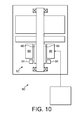
- Vacuum pumps may be used with scientific or manufacturing equipment which is sensitive to magnetic interference. Such equipment includes electron microscopes, focused ion beam instruments and lithography equipment. Turbomolecular pumps of the types described above are often used to achieve the high vacuum typically required in such equipment. A
Turbomolecular pump 90 is shown inFigure 10 . Such pumps are designed for high rotational speeds in the region of 36,000 to 90,000 rpm and may be driven by a permanent magnetbrushless DC motor 92. Such motors have a two-pole configuration in order to minimise the commutation frequency and simplify the design of the drive electronics. Brushless DC motors generally comprise one or morehall effect sensors 94 for sensing rotation of apermanent magnet rotor 96. Therotor 96 extends axially beyond an end of thestator 98 so that the sensors can measure the rotation of the rotor. The extension of the rotor causes increased stray magnetic fields to leak out of the pump and interfere with scientific or manufacturing equipment, even though typically the extension may be only around 5mm. It is desirable to reduce magnetic interference from the motor. - The invention provides a vacuum pump comprising a vacuum pumping mechanism rotatable by a shaft and a brushless motor for rotating said shaft, wherein said motor comprises: a permanent magnet rotor fixed relative to said shaft, said rotor having at least four poles; a stator fixed relative to a pump housing, said stator having non-overlapping stator coils; and motor control means for selective energisation of said stator coils dependent on a relative position of said rotor and said stator so that said rotor can be rotated relative to said stator.
- Other preferred and/or optional features are defined in the accompanying claims.
- In order that the invention may be well understood, an embodiment thereof, which is given by way of example only, will now be described with reference to the drawings in which:
-
Figure 1 is a schematic diagram of a vacuum pump; -
Figure 2 is a view of an axial end of a motor for the vacuum pump shown inFigure 1 ; -
Figure 3 is a simplified representation of a winding arrangement for the motor shown inFigures 1 and2 ; -
Figure 4 is a simplified representation of a winding arrangement for a prior art motor; -
Figure 5 shows a motor control means for the motor shown inFigures 1 and2 ; -
Figure 6 is a schematic representation of a vacuum pump comprising a Holweck type vacuum pumping arrangement driven by the motor shown inFigure 2 ; -
Figure 7 is a schematic representation of a vacuum pump comprising a Gaede or Siegbahn type vacuum pumping arrangement driven by the motor shown inFigure 2 ; -
Figure 8 is a schematic representation of a vacuum pump comprising a Holweck type vacuum pumping arrangement driven by a prior art motor; -
Figure 9 is a schematic representation of a vacuum pump comprising a Gaede or Siegbahn type vacuum pumping arrangement driven by a prior art motor; and -
Figure 10 is a schematic diagram of a prior art vacuum pump. - Referring to
Figure 1 , avacuum pump 10 is shown, which comprises avacuum pumping mechanism 12 mounted for rotation by ashaft 14 and abrushless motor 16 for rotating the shaft. Thevacuum pumping mechanism 12 comprises aturbo pumping mechanism 18 comprising a plurality of pumping stages, and a moleculardrag pumping mechanism 20 comprising at least one pumping stage. Shaft 14 is supported for rotation bybearings 22. - The vacuum pumping mechanism may comprise any one or more types of turbomolecular pumping mechanisms, for instance and without limitation, turbo, Gaede, Siegbahn or Holweck type mechanisms. As shown in
Figure 1 , turbo and Siegbahn mechanisms are shown. - Vacuum pumping mechanisms require rotation at high speed, typically at speeds of at least 20,000 rpm and generally at speeds of between about 36,000 and 90,000 rpm. Such high speeds are necessary to achieve compression from pressures of about 1x10⁻¹⁰ Torr at an inlet of the pump and 1 Torr at an outlet of the pump. Vacuum pumps are considered therefore to be very high speed pumps.
- The
motor 16 comprises apermanent magnet rotor 24 fixed relative to theshaft 14. Therotor 24 has four poles as will be described in greater detail below with reference toFigure 2 . More than four poles may be adopted as required. The motor comprises astator 26 fixed relative to apump housing 28. The stator has non-overlapping stator coils, which are also described in greater detail below with reference toFigure 2 . - A motor control means 30 is operable for commutation of the motor by selective energisation of the stator coils dependent on a relative position of the
rotor 24 and thestator 26 so that the rotor can be rotated relative to the stator for driving thepumping mechanism 12. The motor control means 30 is described in greater detail below with reference toFigure 5 . The motor control means 30 is configured to control selective energisation of the stator coils without a sensor, such as a hall effect or other magnetic field based sensors. Accordingly, therotor 24 is not required to extend beyond thestator 26 as shown inFigure 10 to allow such sensors to function. As a consequence, stray magnetic fields encountered with prior art brushless motors are reduced with the arrangement shown inFigure 1 and therefore,vacuum pump 10 is more suitable for use with scientific or manufacturing equipment which is sensitive to magnetic interference. - An axial end of
motor 16 is shown inFigure 2 . Therotor 24 is generally cylindrical having a radially inner surface which is fixed to a radially outer surface ofshaft 14 for rotation about anaxis 32. The rotor has four generally equal arcuate segments or, if the rotor is of unitary construction, four generally equal arcuate rotor portions, which constitute four poles of the rotor. The north and south poles are arranged alternately around the rotor, each pole extending over no more than 90° aboutaxis 32. Whilst four poles are shown inFigure 2 , more than four poles can be adopted as required. -
Stator 26 is fixed by suitable means relative topump housing 28. The stator has a core with a generally annular peripheral portion, or back-iron, 34 from which sixpole shoes 36 extend radially inwardly. The pole shoes are angularly spaced generally equally about theperipheral portion 34 at an angle of about 60°. The radially inner face of eachshoe 36 is spaced from a radially outer surface ofrotor 24 by an air-gap in which magnetic flux is controlled by operation of the stator in order to control rotation of the rotor. - Although the embodiment shown comprises a three phase motor having four pole rotor and six stator shoes, other combinations of phases, poles and shoes fall within the scope of the present invention. For instance, the motor may comprise any even number of poles equal to or greater than four (4, 6, 8, 10 etc). However, there are disadvantages associated with a multiplicity of poles as this leads to high commutation frequencies which involve complex and expensive processing requirements. Such high frequencies may also generate unacceptable losses within the motor. More or less than three phases may be provided as required, however at least three phases are preferred for providing smooth torque distribution. Where P is the number of poles and M is the number of phases, the number of shoes must be equal to or greater than P/2 x M.
- The stator winding comprises three wires configured to form six non-overlapping stator coils 38. The six stator coils are wound about
respective pole shoes 36, as indicated at A1, B1, C1, A2, B2, C2. Afirst wire 40 is connected betweenelectrical contacts 41 and forms stator coils at A1 and A2. Asecond wire 42 is connected betweenelectrical contacts 43 and forms stator coils at B1 and B2. Athird wire 44 is connected betweenelectrical contacts 45 and forms stator coils at C1 and C2.Electrical contacts frequency converter 60 described hereinafter. As shown by the arrows inFigure 2 , each of the first, second and third wires extend over the axial end ofstator core portion 34 between respective coils A1 and A2, B1 and B1, and C1 and C2. The axial length of the stator is determined by a length ofperipheral portion 36 and an axial extent of the windings which protrude beyond each axial end face ofportion 36. Additionally,wires -
Figure 3 shows the non-overlapping winding arrangement ofFigure 2 , andFigure 4 shows a prior art overlapping arrangement. InFigure 3 , the non-overlapping stator windings can be wound in-situ and occupy less space in an axial and/or circumferential direction of the motor as compared to overlapping windings. In this regard, the space required around and at an axial end of each pole shoe is less for a non-overlapping winding since only one coil is wound around each shoe. Additionally, an overlapping winding arrangement can not be wound in-situ but instead requires a relatively complicated and time consuming winding technique. If a non-overlapping winding arrangement is adopted as in the present invention it is further possible to provide a stator with a segmented stator core. Generally, in such a stator core, each segment comprises one pole shoe and the winding can readily be made prior to integration of segments to form the stator. It is a further advantage in a segmented stator that the stator can be made from a non-sintered composite powder material using standard powder metallurgy processes. Each segment of such a stator can be moulded/cast such that the axial end of the pole shoe is spaced from an axial end of the back-iron (peripheral portion 34) to provide a space for the winding, so that when a winding is formed on the pole shoe the windings do not extend beyond either axial end of the back iron. It will be appreciated therefore that non-overlapping windings have a relatively uncomplicated configuration which is more easily manufactured and allows a reduction in axial and/or radial extent of the stator compared to the prior art configuration shown inFigure 4 . InFigure 4 , thewindings -
Figure 5 shows the motor control means 30. The motor control means is operable to control energisation of the stator coils at A1 and A2, B1 and B2, and C1 and C2 to provide three phase commutation. The motor control means 30 determines a relative angular position of the rotor and the stator by measuring a voltage and current in the stator windings and controls energisation of the stator windings to provide correct commutation.EP0925641 ,EP1189335 andEP1705792 each show control means for commutating a motor without the use of a sensor and the content of each of those applications is incorporated herein by reference. - In more detail, control means 30 comprises a
frequency converter 60 for providing phased energisation of thestator windings 38. Aprocessing unit 62 such as a digital signal processing unit receives a current and a voltage signal of thestator windings 38 and determines in real time a variation in flux in each winding according to the following equation.
- Where in relation to a stator winding, V is voltage, I is the current, R is the resistance, N is the number of turns, A is the cross-sectional area, L is the inductance and B is the magnetic flux density.
- An angular position of the rotor can be determined according to the variation in flux and a position signal output to a
control unit 64 for use in controlling thefrequency converter 60 to achieve correct commutation. - Since vacuum pumps of the type described herein are required to be driven at high rotational speeds, the frequency of commutation of the stator windings must be commensurately high. The use of a rotor with four or more poles requires higher frequency commutation as compared to a two pole motor. Previously therefore it has not been considered desirable to adopt a vacuum pump, which is driven by a motor with a four pole rotor since the frequency of required commutation would be prohibitively high. However, such an increase in frequency has been found to have beneficial effects in a vacuum pump. As the
pump housing 28 shown inFigure 1 is typically made from an electrically conductive material, for instance an aluminium alloy, an increase in the frequency of the alternating magnetic field generated results in an increase in the attenuation effect of the housing by eddy-current shielding. Accordingly, the adoption of a four pole motor in a vacuum pump renders the vacuum pump more suitable for use with sensitive equipment. - When an alternating magnetic field is imposed on a pump housing made from a material of high electrical conductivity or high magnetic permeability, eddy currents are induced in the housing. These eddy currents create a further magnetic field which counteracts the original imposed field so that the magnetic field is reduced as it passes through the pump housing. The skin thickness Tm of the pump housing is a measure of the distance through the housing over which the magnetic field is reduced by a ratio of "e" (approximately 2.72). Therefore, shielding is increased as the skin thickness is reduced. The skin thickness can be calculated according to the formula below.

where ρ is electrical resistivity, µ is magnetic permeability and f is the frequency of the time-varying magnetic field. For materials such as aluminium with low electrical resistivity or materials such as mild steel with high magnetic permeability (above 100 relative magnetic permeabilities), the skin thickness is relatively small and therefore the shielding effect is relatively large. The increased frequency of the four pole rotor further increases the shielding effect. - As described above, a four pole motor requires higher frequency commutation, which ordinarily increases iron losses in the stator. Iron losses WFE can be approximated according to the formula below.
- WFe α Volume x B2 x ω2
where B is flux density and ω is commutation frequency. - As described above, a four pole motor requires higher frequency commutation, which will increase the iron losses in the stator. However, due to the non-overlapping winding arrangement shown in
Figures 2 and3 the copper losses are decreased by avoiding long end windings normally involved in an overlapping winding arrangement. The copper losses are decreased as the resistance of the winding is reduced as less wire is required to form the windings. This reduction in copper loss can be traded against a potential increase in stator iron loss to keep the total losses of the motor similar to the losses in a conventional two pole motor. - Stray magnetic fields are also reduced as the flux in a four pole motor travels a quarter rather than half the motor, and hence extends less radially (lower magnitude of flux density in radial direction). Additionally, stray magnetic fields are additionally reduced as commutation of the motor is calculated as shown in
Figure 5 , and therefore hall effect sensors are not required. As described above in relation to the prior art, the use of hall effect sensors necessitates an extension of the rotor beyond the stator and leads to increased stray magnetic fields. A sensor-less motor is advantageous as it renders the motor more suitable for use with sensitive equipment, such as equipment for one of metrology, imaging or pattern-making. As an alternative to a sensor-less motor, an optical sensor may be used to determine rotation of the rotor and to transmit the determination to the motor control means for control of commutation. - The
motor 16 is reduced in both radial and axial dimension as compared to prior art motors and therefore as shown inFigures 6 and 7 as compared withFigures 8 and 9 ,motor 16 can be used both with Holweck type vacuum pumping mechanisms and with Gaede and Siegbahn type vacuum pumping mechanisms. Therefore it is not necessary to produce multiple different types of motors for different types of pumping mechanisms and thus manufacturing costs can be reduced. It is a further advantage that the reduced dimensions ofmotor 16 allow a more compact vacuum pump.
Claims (12)
- A vacuum pump comprising a vacuum pumping mechanism rotatable by a shaft and a brushless motor for rotating said shaft, wherein said motor comprises:a permanent magnet rotor fixed relative to said shaft, said rotor having at least four poles;a stator fixed relative to a pump housing, said stator having non-overlapping stator coils: andmotor control means for selective energisation of said stator coils dependent on a relative position of said rotor and said stator so that said rotor can be rotated relative to said stator, and wherein said motor control means is configured to energise said stator coils at a frequency which is sufficient to rotate said vacuum pumping mechanism at at least 20,000 revolutions per minute
- A vacuum pump as claimed in claim 1, wherein said vacuum pumping mechanism comprises a turbomolecular pumping mechanism.
- A vacuum pump as claimed in claim 2, wherein said pumping mechanism comprises one of a Holweck, Gaede or Siegbahn pumping mechanism.
- A vacuum pump as claimed in any of the preceding claims, wherein said motor control means comprises an optical sensor for sensing said relative position of said rotor and said stator.
- A vacuum pump as claimed in any of claims 1 to 3, wherein said motor control means is configured to determine said relative position of said rotor and said stator by computation of a magnetic flux in said stator coils.
- A vacuum pump as claimed in claim 5, wherein said flux is computed by measurement of voltage and current in said stator coils.
- A vacuum pump as claimed in any preceding claim for equipment sensitive to magnetic interference.
- A vacuum pump as claimed in claim 7, wherein said equipment is for one of metrology, imaging or pattern-making.
- A vacuum pump as claimed in any preceding claim, comprising a pump housing made from a material of high electrical conductivity or high magnetic permeability.
- A vacuum pump as claimed in claim 9, wherein said material is made from an aluminium alloy.
- A vacuum pump as claimed in any preceding claim, comprising a pump housing made from a material of high magnetic permeability.
- A vacuum pump as claimed in claim 11, wherein said material is made from steel.
Applications Claiming Priority (1)
| Application Number | Priority Date | Filing Date | Title |
|---|---|---|---|
| GBGB0724837.0A GB0724837D0 (en) | 2007-12-20 | 2007-12-20 | vacuum pump |
Publications (3)
| Publication Number | Publication Date |
|---|---|
| EP2072831A2 true EP2072831A2 (en) | 2009-06-24 |
| EP2072831A3 EP2072831A3 (en) | 2012-11-28 |
| EP2072831B1 EP2072831B1 (en) | 2014-06-25 |
Family
ID=39048428
Family Applications (1)
| Application Number | Title | Priority Date | Filing Date |
|---|---|---|---|
| EP08170560.0A Active EP2072831B1 (en) | 2007-12-20 | 2008-12-03 | Vacuum pump |
Country Status (5)
| Country | Link |
|---|---|
| US (1) | US8608459B2 (en) |
| EP (1) | EP2072831B1 (en) |
| JP (1) | JP2009150398A (en) |
| CN (1) | CN101463825B (en) |
| GB (1) | GB0724837D0 (en) |
Cited By (3)
| Publication number | Priority date | Publication date | Assignee | Title |
|---|---|---|---|---|
| DE102014110073A1 (en) | 2014-07-17 | 2016-01-21 | Pfeiffer Vacuum Gmbh | vacuum pump |
| WO2016085400A1 (en) * | 2014-11-27 | 2016-06-02 | Provtagaren Ab | Pump control for low flow volumes |
| WO2018042172A1 (en) * | 2016-09-05 | 2018-03-08 | Edwards Limited | Vacuum pump assembly |
Families Citing this family (4)
| Publication number | Priority date | Publication date | Assignee | Title |
|---|---|---|---|---|
| CN102280965B (en) * | 2010-06-12 | 2013-07-24 | 中国科学院沈阳科学仪器股份有限公司 | Shield motor for vacuum pump |
| US9995291B2 (en) * | 2012-07-25 | 2018-06-12 | Panasonic Appliances Refrigeration Devices Singapore | Sealed compressor and refrigeration unit including sealed compressor |
| CN103457366B (en) * | 2013-09-16 | 2015-01-21 | 北京富特盘式电机有限公司 | Variable frequency speed regulating disk type motor and vacuum pump |
| KR101696710B1 (en) * | 2015-01-28 | 2017-01-16 | 엘지전자 주식회사 | BLDC Motor and Cleaner having the same |
Citations (2)
| Publication number | Priority date | Publication date | Assignee | Title |
|---|---|---|---|---|
| EP0925641A1 (en) | 1996-09-10 | 1999-06-30 | Societe De Mecanique Magnetique | Device for sensing the angular position for controlling a synchronous motor excited by a permanent magnet |
| EP1189335A2 (en) | 2000-09-18 | 2002-03-20 | Seiko Instruments Inc. | Control circuit and apparatus of brush-less motor and vacuum pump |
Family Cites Families (22)
| Publication number | Priority date | Publication date | Assignee | Title |
|---|---|---|---|---|
| IT717632A (en) | 1963-03-12 | |||
| DE3923267A1 (en) | 1989-07-14 | 1991-01-24 | Wap Reinigungssysteme | ELECTRONICALLY COMMUTED MOTOR FOR VACUUM CLEANERS AND THE LIKE |
| CN1110376A (en) * | 1994-04-16 | 1995-10-18 | 储继国 | Driven molecular pump |
| JP3518901B2 (en) * | 1994-09-09 | 2004-04-12 | 株式会社日立製作所 | Driving method and driving device for brushless DC motor |
| IT235946Y1 (en) * | 1995-09-29 | 2000-07-18 | Bitron Spa | POWER GROUP FOR POWER STEERING |
| KR19990013313A (en) | 1998-02-11 | 1999-02-25 | 이이수 | Variable Voltage Outputless Rectifier DC Motor |
| EP1024294A3 (en) | 1999-01-29 | 2002-03-13 | Ibiden Co., Ltd. | Motor and turbo-molecular pump |
| JP2000220640A (en) | 1999-01-29 | 2000-08-08 | Ibiden Co Ltd | Motor and turbo-molecular pump |
| US6450772B1 (en) * | 1999-10-18 | 2002-09-17 | Sarcos, Lc | Compact molecular drag vacuum pump |
| JP4566354B2 (en) | 2000-07-21 | 2010-10-20 | 株式会社大阪真空機器製作所 | Molecular pump |
| JP2003153514A (en) | 2001-11-15 | 2003-05-23 | Matsushita Electric Ind Co Ltd | Brushless motor |
| JP3690341B2 (en) | 2001-12-04 | 2005-08-31 | ダイキン工業株式会社 | Brushless DC motor driving method and apparatus |
| JP3740083B2 (en) | 2002-03-19 | 2006-01-25 | 三菱重工業株式会社 | DC brushless motor and turbo molecular pump |
| DE10302987A1 (en) * | 2003-01-25 | 2004-08-05 | Inficon Gmbh | Leak detector with an inlet |
| US7242175B2 (en) * | 2003-08-08 | 2007-07-10 | Stmicroelectronics, Inc. | Determining rotation of a freewheeling motor |
| US7021888B2 (en) * | 2003-12-16 | 2006-04-04 | Universities Research Association, Inc. | Ultra-high speed vacuum pump system with first stage turbofan and second stage turbomolecular pump |
| GB2410848A (en) * | 2004-02-05 | 2005-08-10 | Dyson Ltd | Voltage compensation in switched reluctance motor |
| RU2260140C1 (en) | 2004-05-17 | 2005-09-10 | Ибадуллаев Гаджикадир Алиярович | Internal combustion diesel engine |
| GB0411426D0 (en) * | 2004-05-21 | 2004-06-23 | Boc Group Plc | Pumping arrangement |
| CN101228679B (en) | 2005-07-19 | 2012-12-12 | 株式会社电装 | Motor and control unit thereof |
| DE102005041501A1 (en) * | 2005-09-01 | 2007-03-08 | Leybold Vacuum Gmbh | Vacuum turbomolecular pump |
| JP5167631B2 (en) * | 2006-11-30 | 2013-03-21 | 株式会社デンソー | Motor control method and motor control apparatus using the same |
-
2007
- 2007-12-20 GB GBGB0724837.0A patent/GB0724837D0/en not_active Ceased
-
2008
- 2008-12-03 EP EP08170560.0A patent/EP2072831B1/en active Active
- 2008-12-11 US US12/316,292 patent/US8608459B2/en active Active
- 2008-12-19 CN CN2008101839846A patent/CN101463825B/en active Active
- 2008-12-22 JP JP2008325565A patent/JP2009150398A/en active Pending
Patent Citations (3)
| Publication number | Priority date | Publication date | Assignee | Title |
|---|---|---|---|---|
| EP0925641A1 (en) | 1996-09-10 | 1999-06-30 | Societe De Mecanique Magnetique | Device for sensing the angular position for controlling a synchronous motor excited by a permanent magnet |
| EP1189335A2 (en) | 2000-09-18 | 2002-03-20 | Seiko Instruments Inc. | Control circuit and apparatus of brush-less motor and vacuum pump |
| EP1705792A1 (en) | 2000-09-18 | 2006-09-27 | BOC Edwards Japan Limited | Brush-less motor with control circuit |
Cited By (5)
| Publication number | Priority date | Publication date | Assignee | Title |
|---|---|---|---|---|
| DE102014110073A1 (en) | 2014-07-17 | 2016-01-21 | Pfeiffer Vacuum Gmbh | vacuum pump |
| JP2016025845A (en) * | 2014-07-17 | 2016-02-08 | プファイファー・ヴァキューム・ゲーエムベーハー | Vacuum pump |
| EP2985883A2 (en) | 2014-07-17 | 2016-02-17 | Pfeiffer Vacuum Gmbh | Vacuum pump |
| WO2016085400A1 (en) * | 2014-11-27 | 2016-06-02 | Provtagaren Ab | Pump control for low flow volumes |
| WO2018042172A1 (en) * | 2016-09-05 | 2018-03-08 | Edwards Limited | Vacuum pump assembly |
Also Published As
| Publication number | Publication date |
|---|---|
| CN101463825B (en) | 2013-03-13 |
| US20090162220A1 (en) | 2009-06-25 |
| JP2009150398A (en) | 2009-07-09 |
| GB0724837D0 (en) | 2008-01-30 |
| EP2072831B1 (en) | 2014-06-25 |
| CN101463825A (en) | 2009-06-24 |
| US8608459B2 (en) | 2013-12-17 |
| EP2072831A3 (en) | 2012-11-28 |
Similar Documents
| Publication | Publication Date | Title |
|---|---|---|
| EP2072831B1 (en) | Vacuum pump | |
| US5939813A (en) | Gap tube motor | |
| JP5105029B2 (en) | Winding method and structure of stator for rotation detector and electric motor having rotation detector | |
| US20100013333A1 (en) | Magnetic radial bearing having permanent-magnet generated magnetic bias, and a magnetic bearing system having a magnetic radial bearing of this type | |
| EP0994555A2 (en) | Subsynchronous reluctance electrical machine | |
| JP5110233B2 (en) | Winding method of rotation detector stator, winding structure thereof and electric motor using rotation detector | |
| US20210265905A1 (en) | Electrical Machine with Electric Motor and Magnetic Gear | |
| KR20010076182A (en) | Cage-type induction motor for high rotational speeds | |
| US10594235B2 (en) | Axial flux motor with built-in optical encoder | |
| CN1156970A (en) | Drive unit for transport devices | |
| US9698647B2 (en) | Electric machine with magnetic sensor | |
| CN102857054A (en) | Electromotor | |
| EP0773619B1 (en) | Axial-flow induction motor | |
| US5542825A (en) | Turbomolecular vacuum pump | |
| JP7401305B2 (en) | vacuum pump assembly | |
| JP2006230142A (en) | Small motor | |
| JPH10288191A (en) | Pump | |
| CN106712333A (en) | Design method of no-commutating permanent magnet direct current rotating motor | |
| JPH0746802A (en) | Electric motor | |
| JP4621661B2 (en) | Rotating machine | |
| CN109845072B (en) | Electric motor with diametrically arranged coils | |
| CN117501072A (en) | Rotation detector | |
| JP2021052568A (en) | Electric motor | |
| JPH01194843A (en) | Motor rotor | |
| JP2007244169A (en) | Motor |
Legal Events
| Date | Code | Title | Description |
|---|---|---|---|
| PUAI | Public reference made under article 153(3) epc to a published international application that has entered the european phase |
Free format text: ORIGINAL CODE: 0009012 |
|
| AK | Designated contracting states |
Kind code of ref document: A2 Designated state(s): AT BE BG CH CY CZ DE DK EE ES FI FR GB GR HR HU IE IS IT LI LT LU LV MC MT NL NO PL PT RO SE SI SK TR |
|
| AX | Request for extension of the european patent |
Extension state: AL BA MK RS |
|
| PUAL | Search report despatched |
Free format text: ORIGINAL CODE: 0009013 |
|
| AK | Designated contracting states |
Kind code of ref document: A3 Designated state(s): AT BE BG CH CY CZ DE DK EE ES FI FR GB GR HR HU IE IS IT LI LT LU LV MC MT NL NO PL PT RO SE SI SK TR |
|
| AX | Request for extension of the european patent |
Extension state: AL BA MK RS |
|
| RIC1 | Information provided on ipc code assigned before grant |
Ipc: H02K 29/12 20060101ALI20121024BHEP Ipc: F04D 25/06 20060101ALI20121024BHEP Ipc: H02K 11/00 20060101ALI20121024BHEP Ipc: F04D 19/04 20060101AFI20121024BHEP Ipc: H02P 6/18 20060101ALI20121024BHEP |
|
| 17P | Request for examination filed |
Effective date: 20130528 |
|
| RBV | Designated contracting states (corrected) |
Designated state(s): AT BE BG CH CY CZ DE DK EE ES FI FR GB GR HR HU IE IS IT LI LT LU LV MC MT NL NO PL PT RO SE SI SK TR |
|
| AKX | Designation fees paid |
Designated state(s): AT BE BG CH CY CZ DE DK EE ES FI FR GB GR HR HU IE IS IT LI LT LU LV MC MT NL NO PL PT RO SE SI SK TR |
|
| GRAP | Despatch of communication of intention to grant a patent |
Free format text: ORIGINAL CODE: EPIDOSNIGR1 |
|
| INTG | Intention to grant announced |
Effective date: 20131126 |
|
| GRAP | Despatch of communication of intention to grant a patent |
Free format text: ORIGINAL CODE: EPIDOSNIGR1 |
|
| GRAS | Grant fee paid |
Free format text: ORIGINAL CODE: EPIDOSNIGR3 |
|
| INTG | Intention to grant announced |
Effective date: 20140428 |
|
| GRAA | (expected) grant |
Free format text: ORIGINAL CODE: 0009210 |
|
| AK | Designated contracting states |
Kind code of ref document: B1 Designated state(s): AT BE BG CH CY CZ DE DK EE ES FI FR GB GR HR HU IE IS IT LI LT LU LV MC MT NL NO PL PT RO SE SI SK TR |
|
| REG | Reference to a national code |
Ref country code: GB Ref legal event code: FG4D |
|
| REG | Reference to a national code |
Ref country code: CH Ref legal event code: EP |
|
| REG | Reference to a national code |
Ref country code: AT Ref legal event code: REF Ref document number: 674889 Country of ref document: AT Kind code of ref document: T Effective date: 20140715 |
|
| REG | Reference to a national code |
Ref country code: IE Ref legal event code: FG4D |
|
| REG | Reference to a national code |
Ref country code: DE Ref legal event code: R096 Ref document number: 602008032953 Country of ref document: DE Effective date: 20140807 |
|
| REG | Reference to a national code |
Ref country code: NL Ref legal event code: T3 |
|
| PG25 | Lapsed in a contracting state [announced via postgrant information from national office to epo] |
Ref country code: CY Free format text: LAPSE BECAUSE OF FAILURE TO SUBMIT A TRANSLATION OF THE DESCRIPTION OR TO PAY THE FEE WITHIN THE PRESCRIBED TIME-LIMIT Effective date: 20140625 Ref country code: GR Free format text: LAPSE BECAUSE OF FAILURE TO SUBMIT A TRANSLATION OF THE DESCRIPTION OR TO PAY THE FEE WITHIN THE PRESCRIBED TIME-LIMIT Effective date: 20140926 Ref country code: FI Free format text: LAPSE BECAUSE OF FAILURE TO SUBMIT A TRANSLATION OF THE DESCRIPTION OR TO PAY THE FEE WITHIN THE PRESCRIBED TIME-LIMIT Effective date: 20140625 Ref country code: LT Free format text: LAPSE BECAUSE OF FAILURE TO SUBMIT A TRANSLATION OF THE DESCRIPTION OR TO PAY THE FEE WITHIN THE PRESCRIBED TIME-LIMIT Effective date: 20140625 Ref country code: NO Free format text: LAPSE BECAUSE OF FAILURE TO SUBMIT A TRANSLATION OF THE DESCRIPTION OR TO PAY THE FEE WITHIN THE PRESCRIBED TIME-LIMIT Effective date: 20140925 |
|
| REG | Reference to a national code |
Ref country code: AT Ref legal event code: MK05 Ref document number: 674889 Country of ref document: AT Kind code of ref document: T Effective date: 20140625 |
|
| REG | Reference to a national code |
Ref country code: LT Ref legal event code: MG4D |
|
| PG25 | Lapsed in a contracting state [announced via postgrant information from national office to epo] |
Ref country code: SE Free format text: LAPSE BECAUSE OF FAILURE TO SUBMIT A TRANSLATION OF THE DESCRIPTION OR TO PAY THE FEE WITHIN THE PRESCRIBED TIME-LIMIT Effective date: 20140625 Ref country code: HR Free format text: LAPSE BECAUSE OF FAILURE TO SUBMIT A TRANSLATION OF THE DESCRIPTION OR TO PAY THE FEE WITHIN THE PRESCRIBED TIME-LIMIT Effective date: 20140625 Ref country code: LV Free format text: LAPSE BECAUSE OF FAILURE TO SUBMIT A TRANSLATION OF THE DESCRIPTION OR TO PAY THE FEE WITHIN THE PRESCRIBED TIME-LIMIT Effective date: 20140625 |
|
| PG25 | Lapsed in a contracting state [announced via postgrant information from national office to epo] |
Ref country code: ES Free format text: LAPSE BECAUSE OF FAILURE TO SUBMIT A TRANSLATION OF THE DESCRIPTION OR TO PAY THE FEE WITHIN THE PRESCRIBED TIME-LIMIT Effective date: 20140625 Ref country code: PT Free format text: LAPSE BECAUSE OF FAILURE TO SUBMIT A TRANSLATION OF THE DESCRIPTION OR TO PAY THE FEE WITHIN THE PRESCRIBED TIME-LIMIT Effective date: 20141027 Ref country code: RO Free format text: LAPSE BECAUSE OF FAILURE TO SUBMIT A TRANSLATION OF THE DESCRIPTION OR TO PAY THE FEE WITHIN THE PRESCRIBED TIME-LIMIT Effective date: 20140625 Ref country code: EE Free format text: LAPSE BECAUSE OF FAILURE TO SUBMIT A TRANSLATION OF THE DESCRIPTION OR TO PAY THE FEE WITHIN THE PRESCRIBED TIME-LIMIT Effective date: 20140625 Ref country code: SK Free format text: LAPSE BECAUSE OF FAILURE TO SUBMIT A TRANSLATION OF THE DESCRIPTION OR TO PAY THE FEE WITHIN THE PRESCRIBED TIME-LIMIT Effective date: 20140625 |
|
| PG25 | Lapsed in a contracting state [announced via postgrant information from national office to epo] |
Ref country code: IS Free format text: LAPSE BECAUSE OF FAILURE TO SUBMIT A TRANSLATION OF THE DESCRIPTION OR TO PAY THE FEE WITHIN THE PRESCRIBED TIME-LIMIT Effective date: 20141025 Ref country code: PL Free format text: LAPSE BECAUSE OF FAILURE TO SUBMIT A TRANSLATION OF THE DESCRIPTION OR TO PAY THE FEE WITHIN THE PRESCRIBED TIME-LIMIT Effective date: 20140625 Ref country code: AT Free format text: LAPSE BECAUSE OF FAILURE TO SUBMIT A TRANSLATION OF THE DESCRIPTION OR TO PAY THE FEE WITHIN THE PRESCRIBED TIME-LIMIT Effective date: 20140625 |
|
| REG | Reference to a national code |
Ref country code: DE Ref legal event code: R097 Ref document number: 602008032953 Country of ref document: DE |
|
| PG25 | Lapsed in a contracting state [announced via postgrant information from national office to epo] |
Ref country code: DK Free format text: LAPSE BECAUSE OF FAILURE TO SUBMIT A TRANSLATION OF THE DESCRIPTION OR TO PAY THE FEE WITHIN THE PRESCRIBED TIME-LIMIT Effective date: 20140625 |
|
| PLBE | No opposition filed within time limit |
Free format text: ORIGINAL CODE: 0009261 |
|
| STAA | Information on the status of an ep patent application or granted ep patent |
Free format text: STATUS: NO OPPOSITION FILED WITHIN TIME LIMIT |
|
| 26N | No opposition filed |
Effective date: 20150326 |
|
| PG25 | Lapsed in a contracting state [announced via postgrant information from national office to epo] |
Ref country code: BE Free format text: LAPSE BECAUSE OF FAILURE TO SUBMIT A TRANSLATION OF THE DESCRIPTION OR TO PAY THE FEE WITHIN THE PRESCRIBED TIME-LIMIT Effective date: 20140625 |
|
| PG25 | Lapsed in a contracting state [announced via postgrant information from national office to epo] |
Ref country code: LU Free format text: LAPSE BECAUSE OF FAILURE TO SUBMIT A TRANSLATION OF THE DESCRIPTION OR TO PAY THE FEE WITHIN THE PRESCRIBED TIME-LIMIT Effective date: 20141203 |
|
| REG | Reference to a national code |
Ref country code: CH Ref legal event code: PL |
|
| REG | Reference to a national code |
Ref country code: IE Ref legal event code: MM4A |
|
| PG25 | Lapsed in a contracting state [announced via postgrant information from national office to epo] |
Ref country code: IE Free format text: LAPSE BECAUSE OF NON-PAYMENT OF DUE FEES Effective date: 20141203 Ref country code: LI Free format text: LAPSE BECAUSE OF NON-PAYMENT OF DUE FEES Effective date: 20141231 Ref country code: CH Free format text: LAPSE BECAUSE OF NON-PAYMENT OF DUE FEES Effective date: 20141231 |
|
| PG25 | Lapsed in a contracting state [announced via postgrant information from national office to epo] |
Ref country code: SI Free format text: LAPSE BECAUSE OF FAILURE TO SUBMIT A TRANSLATION OF THE DESCRIPTION OR TO PAY THE FEE WITHIN THE PRESCRIBED TIME-LIMIT Effective date: 20140625 |
|
| REG | Reference to a national code |
Ref country code: FR Ref legal event code: PLFP Year of fee payment: 8 |
|
| PG25 | Lapsed in a contracting state [announced via postgrant information from national office to epo] |
Ref country code: MC Free format text: LAPSE BECAUSE OF FAILURE TO SUBMIT A TRANSLATION OF THE DESCRIPTION OR TO PAY THE FEE WITHIN THE PRESCRIBED TIME-LIMIT Effective date: 20140625 Ref country code: BG Free format text: LAPSE BECAUSE OF FAILURE TO SUBMIT A TRANSLATION OF THE DESCRIPTION OR TO PAY THE FEE WITHIN THE PRESCRIBED TIME-LIMIT Effective date: 20140625 |
|
| PG25 | Lapsed in a contracting state [announced via postgrant information from national office to epo] |
Ref country code: MT Free format text: LAPSE BECAUSE OF FAILURE TO SUBMIT A TRANSLATION OF THE DESCRIPTION OR TO PAY THE FEE WITHIN THE PRESCRIBED TIME-LIMIT Effective date: 20140625 Ref country code: HU Free format text: LAPSE BECAUSE OF FAILURE TO SUBMIT A TRANSLATION OF THE DESCRIPTION OR TO PAY THE FEE WITHIN THE PRESCRIBED TIME-LIMIT; INVALID AB INITIO Effective date: 20081203 Ref country code: TR Free format text: LAPSE BECAUSE OF FAILURE TO SUBMIT A TRANSLATION OF THE DESCRIPTION OR TO PAY THE FEE WITHIN THE PRESCRIBED TIME-LIMIT Effective date: 20140625 |
|
| REG | Reference to a national code |
Ref country code: FR Ref legal event code: PLFP Year of fee payment: 9 |
|
| PG25 | Lapsed in a contracting state [announced via postgrant information from national office to epo] |
Ref country code: IT Free format text: LAPSE BECAUSE OF NON-PAYMENT OF DUE FEES Effective date: 20151203 |
|
| PG25 | Lapsed in a contracting state [announced via postgrant information from national office to epo] |
Ref country code: IT Free format text: LAPSE BECAUSE OF NON-PAYMENT OF DUE FEES Effective date: 20151203 |
|
| PGRI | Patent reinstated in contracting state [announced from national office to epo] |
Ref country code: IT Effective date: 20170710 |
|
| REG | Reference to a national code |
Ref country code: FR Ref legal event code: PLFP Year of fee payment: 10 |
|
| REG | Reference to a national code |
Ref country code: DE Ref legal event code: R082 Ref document number: 602008032953 Country of ref document: DE Representative=s name: FLEUCHAUS & GALLO PARTNERSCHAFT MBB PATENTANWA, DE Ref country code: DE Ref legal event code: R082 Ref document number: 602008032953 Country of ref document: DE Representative=s name: FLEUCHAUS & GALLO PARTNERSCHAFT MBB, DE Ref country code: DE Ref legal event code: R081 Ref document number: 602008032953 Country of ref document: DE Owner name: EDWARDS LTD., BURGESS HILL, GB Free format text: FORMER OWNER: EDWARDS LTD., CRAWLEY, WEST SUSSEX, GB |
|
| REG | Reference to a national code |
Ref country code: FR Ref legal event code: CA Effective date: 20180906 |
|
| REG | Reference to a national code |
Ref country code: DE Ref legal event code: R082 Ref document number: 602008032953 Country of ref document: DE Representative=s name: FLEUCHAUS & GALLO PARTNERSCHAFT MBB - PATENT- , DE Ref country code: DE Ref legal event code: R082 Ref document number: 602008032953 Country of ref document: DE Representative=s name: FLEUCHAUS & GALLO PARTNERSCHAFT MBB PATENTANWA, DE |
|
| PGFP | Annual fee paid to national office [announced via postgrant information from national office to epo] |
Ref country code: DE Payment date: 20221228 Year of fee payment: 15 |
|
| P01 | Opt-out of the competence of the unified patent court (upc) registered |
Effective date: 20230425 |
|
| PGFP | Annual fee paid to national office [announced via postgrant information from national office to epo] |
Ref country code: GB Payment date: 20231227 Year of fee payment: 16 |
|
| PGFP | Annual fee paid to national office [announced via postgrant information from national office to epo] |
Ref country code: NL Payment date: 20231226 Year of fee payment: 16 Ref country code: IT Payment date: 20231220 Year of fee payment: 16 Ref country code: FR Payment date: 20231227 Year of fee payment: 16 Ref country code: CZ Payment date: 20231123 Year of fee payment: 16 |