EP2072816A1 - Drive system using mechanical impulse conversion, preferably for missiles - Google Patents
Drive system using mechanical impulse conversion, preferably for missiles Download PDFInfo
- Publication number
- EP2072816A1 EP2072816A1 EP07150051A EP07150051A EP2072816A1 EP 2072816 A1 EP2072816 A1 EP 2072816A1 EP 07150051 A EP07150051 A EP 07150051A EP 07150051 A EP07150051 A EP 07150051A EP 2072816 A1 EP2072816 A1 EP 2072816A1
- Authority
- EP
- European Patent Office
- Prior art keywords
- drive
- rotor
- impact
- bodies
- translational
- Prior art date
- Legal status (The legal status is an assumption and is not a legal conclusion. Google has not performed a legal analysis and makes no representation as to the accuracy of the status listed.)
- Withdrawn
Links
- 238000006243 chemical reaction Methods 0.000 title claims description 10
- 230000033001 locomotion Effects 0.000 claims abstract description 120
- 230000005540 biological transmission Effects 0.000 claims abstract description 38
- 230000005484 gravity Effects 0.000 claims abstract description 9
- 230000035939 shock Effects 0.000 claims description 44
- 230000001133 acceleration Effects 0.000 claims description 39
- 230000003993 interaction Effects 0.000 claims description 14
- 125000004122 cyclic group Chemical group 0.000 claims description 8
- 230000015572 biosynthetic process Effects 0.000 claims description 6
- 230000009471 action Effects 0.000 claims description 5
- 230000035515 penetration Effects 0.000 claims description 2
- 238000004321 preservation Methods 0.000 claims description 2
- 239000007787 solid Substances 0.000 claims description 2
- 239000013598 vector Substances 0.000 description 29
- 238000000034 method Methods 0.000 description 22
- 230000008569 process Effects 0.000 description 22
- 230000005477 standard model Effects 0.000 description 15
- 230000000694 effects Effects 0.000 description 10
- 230000036961 partial effect Effects 0.000 description 10
- 230000003116 impacting effect Effects 0.000 description 8
- 230000000284 resting effect Effects 0.000 description 8
- 230000008859 change Effects 0.000 description 7
- 230000009467 reduction Effects 0.000 description 5
- 230000003042 antagnostic effect Effects 0.000 description 4
- 230000003321 amplification Effects 0.000 description 3
- 230000007717 exclusion Effects 0.000 description 3
- 230000036540 impulse transmission Effects 0.000 description 3
- 238000003199 nucleic acid amplification method Methods 0.000 description 3
- 230000002093 peripheral effect Effects 0.000 description 3
- 230000002441 reversible effect Effects 0.000 description 3
- 230000007704 transition Effects 0.000 description 3
- 230000002146 bilateral effect Effects 0.000 description 2
- 239000002131 composite material Substances 0.000 description 2
- 230000007423 decrease Effects 0.000 description 2
- 238000004134 energy conservation Methods 0.000 description 2
- 239000007789 gas Substances 0.000 description 2
- 238000005096 rolling process Methods 0.000 description 2
- 230000009466 transformation Effects 0.000 description 2
- 239000005557 antagonist Substances 0.000 description 1
- 238000002485 combustion reaction Methods 0.000 description 1
- 238000010276 construction Methods 0.000 description 1
- 230000001419 dependent effect Effects 0.000 description 1
- 230000005672 electromagnetic field Effects 0.000 description 1
- 230000002708 enhancing effect Effects 0.000 description 1
- 230000002349 favourable effect Effects 0.000 description 1
- 239000000446 fuel Substances 0.000 description 1
- 230000006266 hibernation Effects 0.000 description 1
- 230000002427 irreversible effect Effects 0.000 description 1
- 230000000670 limiting effect Effects 0.000 description 1
- 239000007788 liquid Substances 0.000 description 1
- 230000000116 mitigating effect Effects 0.000 description 1
- 238000001208 nuclear magnetic resonance pulse sequence Methods 0.000 description 1
- 239000007800 oxidant agent Substances 0.000 description 1
- 230000002688 persistence Effects 0.000 description 1
- 230000005855 radiation Effects 0.000 description 1
- 230000000087 stabilizing effect Effects 0.000 description 1
- 230000001629 suppression Effects 0.000 description 1
- 230000009885 systemic effect Effects 0.000 description 1
Images


Classifications
-
- F—MECHANICAL ENGINEERING; LIGHTING; HEATING; WEAPONS; BLASTING
- F03—MACHINES OR ENGINES FOR LIQUIDS; WIND, SPRING, OR WEIGHT MOTORS; PRODUCING MECHANICAL POWER OR A REACTIVE PROPULSIVE THRUST, NOT OTHERWISE PROVIDED FOR
- F03G—SPRING, WEIGHT, INERTIA OR LIKE MOTORS; MECHANICAL-POWER PRODUCING DEVICES OR MECHANISMS, NOT OTHERWISE PROVIDED FOR OR USING ENERGY SOURCES NOT OTHERWISE PROVIDED FOR
- F03G3/00—Other motors, e.g. gravity or inertia motors
-
- B—PERFORMING OPERATIONS; TRANSPORTING
- B64—AIRCRAFT; AVIATION; COSMONAUTICS
- B64G—COSMONAUTICS; VEHICLES OR EQUIPMENT THEREFOR
- B64G1/00—Cosmonautic vehicles
- B64G1/22—Parts of, or equipment specially adapted for fitting in or to, cosmonautic vehicles
- B64G1/40—Arrangements or adaptations of propulsion systems
- B64G1/409—Unconventional spacecraft propulsion systems
Definitions
- the invention relates to mechanical pulse generation on autonomous, self-contained, shape-consistent and complex technical bodies (e.g., spacecraft) by internal release of force as a result of energy input.
- the subject of the invention is the technical special case in which the conservation laws of physics enable a rectilinear acceleration of such bodies.
- a direction-defined vector is associated with the colliding and collided body, which describes the movement variable "momentum" (vector impulse).
- the respective sense of direction is described by the sign.
- the vector pulse can increase in the direction of impact, as described for the centric impact. This always happens when the impacted body has a lower kinetic energy density due to its larger mass after impact than it had before the impacting body of smaller mass. For that one experiences a recoil.
- the pulse vector sum remains constant, the pulse sum sum increases.
- the kinetic energy density of both bodies is mass-dependent even after the impact.
- This special case is the eccentric elastic impact of a simultaneously translatory and rotationally moving body on a free body resting.
- This refers to the drive principle according to the invention.
- we make the formal justification of the lawfulness of the result, the description of the reference shocking process, the application of this Process on the standard model of a system to be accelerated, the identification of the basic characteristics of the drive principle and the essential execution consequences.
- a bumping free rigid elastic body with eccentric mass concentration which is in a plane motion while rectilinear and rotating about its center of gravity, ideally meets eccentric to a resting elastic punctiform free collided body of the same mass.
- Translational and rotational movement of the impacting body have equal magnitude impulses. Both movements correspond to their own kinetic energy amount.
- the translational momentum of the colliding body is identical to the common momentum vector sum and the energy of the colliding body is identical to the total kinetic energy. Any change in the momentum vector sum in the two - body system due to the translational - rotational double impact would correspond to an acceleration of the system center of mass. However, the momentum vector sum would only remain constant if the rotational momentum were equally distributed to both bodies during its distribution. The impacting body would receive the same translational impulse reduction as the impacted body would have an impulse amplification.
- the cause is the simultaneity of two types of movement in the colliding body and its interaction with both movements at the same time in the joint double impact. This results in kinetic energy conservation as a peculiarity of a pulse distribution between the bodies, which combines the characteristics of the impulse-enhancing in the impulse direction elastic shock with features of the recoil-preventing inelastic impact.
- the elastic impacting body Due to its double motion, the elastic impacting body has a higher kinetic energy density than the collapsed body and at the same time has the ability to initiate a recoilless kinetic interaction even without deformation work by internal transformation from rotational to translational kinetic energy. Both together make the described shock conditions unique.
- the description of the REFERENCE JUMP is based on two rigid elastic masses of the same body, namely a body B, consisting of a point mass and a rotor body R, consisting of two equally equal half-size point masses R x and R y , which are spaced apart by a massless rod element a symmetrical dumbbell are connected to the axis of rotation in the center of gravity.
- a body B consisting of a point mass
- R rotor body
- R consisting of two equally equal half-size point masses R x and R y
- a massless rod element a symmetrical dumbbell are connected to the axis of rotation in the center of gravity.
- Common shock location of both bodies is the touch of the points B and R X , so centric on the body B and at most eccentric on the body R.
- the rotor body dumbbell rotor is in double plane motion. His two basic movements translation and rotation he received by a previous acceleration. Accordingly, it has a translational basic impulse p 0 and a basic rotatory impulse L 0 . Rotational and translational motion have equal kinetic energy, the momentum of one motion is at full conversion relative to constant mass equal to the momentum of the other motion. The sense of direction of the pulse p 0 is the direction of impact.
- the dumbbell rotor R strikes the resting body B with a vertical, smooth eccentric impact, specifically centrically for this body. Both basic pulses are transmitted. Combined in a shock event, two partial impacts take place at the same place, which are separately writable and to be balanced together.
- the partial impact 1 is the eccentric shock of the rotational dumbbell dumbbell out of translational motion out; the partial impact 2 is the eccentric shock of translational dumbbell dumbbell out of rotational movement.
- the basic rotatory impulse L 0 is the internal antagonist of Lp.
- the pulse vector sum after the reference shock process is different from before. This is the prerequisite for a system-related vector impulse asymmetry.
- the magnitude of the pulse momentum Lp under other conditions than those of the reference shock process depends on the mass moment of inertia of the rotor body, the mass ratio between the two bodies, and the tuned ratio of the two fundamental pulses.
- the system consists of four bodies: a hollow inelastic envelope COV smaller but not negligible, mass closing off the system spatially and three elastic bodies freely moving in one plane inside it.
- the prism-shaped enveloping body has mirror-symmetrical vertical side surfaces.
- the elastic bodies are the two bodies R and B from the reference shock observation and another body B a , which is the body B, hereinafter referred to as the body B b , is similar. These three bodies are adjacent to each other near the system center, where R is positioned between B a and B b .
- the internal movement of the elastic body refers to the enveloping body, the location and movement of all four bodies the common center of gravity, on the other hand, is an arbitrary external inertial system.
- the radius axis of the stationary dumbbell rotor is aligned perpendicular thereto.
- the system axis meets opposite enveloping body surfaces at the central points C1 and C2.
- the bodies B a and R are frictionally tight, while R and B b are adjacent at a distance.
- the point R x1 is located somewhat less eccentrically on the dumbbell rotor than the point mass R x in order for the dumbbell rotor during force impulse Ft to effect the energy and impulse distribution on both partial movements assumed in the reference impact process.
- the translational movement direction of the dumbbell rotor is the intended drive direction.
- the three bodies B a , B b and R have the unequal translational pulses p a , p b and P R obtained. The largest is the momentum p b .
- the pulses p R and p b act in the drive direction, the pulse p a against them.
- the antagonistic pulses p a and p b are transmitted to the envelope. Their sum gives the resulting net translational impulse p comp . It describes the movement change of the bodies B a , B b and COV in the drive direction resulting from joint acceleration.
- the body R Due to its lower speed than that of the leading body B b and its higher speed than that of the body group COV / B a / B b , the body R also strikes time-displaced at location C2 on the inelastic envelope COV, where it remains.
- the four bodies of the system are in stable positive connection.
- the total impulse vector sum of the system has increased.
- the force impact Ft elastic shock 1 took place at the location S1 close to the center, the elastic impact at location S2.
- the dumbbell rotor R moves in the section S1 / C2, the body B a in the section S1 / C1 and the body B b in the section S2 / C2. With the onset of the final state, a sequence of movements is completed and their momentum balancing completed.
- the system experiences an external acceleration.
- the transition from the inner final state to the inner initial state it remains in a uniform external motion.
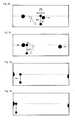
- FIGS. 2a to 2e The standard model of the system is linked by the attached FIGS. 2a to 2e explained in more detail, with the clarity of the marking of the body and places on the FIG. 2a was limited and where the Fig. 2a and 2 B the initial state of the system before and at the momentum the Fig. 2c and 2d the intermediate state of the system before and after the reference shock operation and the Fig. 2e the final state of the system represent.
- the underlying principle of the standard model also applies under real execution-technical adjustments and restrictions. These may concern the position of the location S1 for the elastic shock 1 as well as the change in the translational velocities after the elastic shock 2, such as the ratio of the pulses L 0 and p 0 on the dumbbell rotor, such as the distance of the impact locations S1 and S2 and how the replacement of vertical shocks on the dumbbell rotor by impacts with only sufficiently steep impact angle.
- the sense of the technical execution corresponds to the fact that then especially the mass of the envelope becomes large.
- Physically characteristic of the principle is the kinetic interaction of bodies in a closed system, in which two types of inertia take effect simultaneously in one body, in which the ratio of their inert masses differs between the bodies from the ratio of their acting inertial forces, at which a collision sequence with two changes of different pulse types and two times the interaction of inertia and moment of inertia occurs when an additional internal rotational intermediate pulse occurs, in which the total of the pulse transmissions is accompanied by an increase of the pulse vector sum and results in a resulting outer translational system pulse.
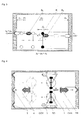
- FIG. 3 The drive principle according to the invention, derived from the reference impact process and the standard model, with the ability to constantly impart drive pulses to an autonomous vehicle without mass loss in a cyclical cyclic mode of operation, is summarized in FIG. 3 shown. For the sake of clarity, will be in FIG. 3 as in the FIGS. 2a to 2e waived observance of mass symmetry and impact centric.
- all drive movements temporarily transition to a system-related relative resting state and alternate with returning provisioning. For this all impact impacts on the chamber wall carry inelastic character.
- the rotors combine translational and rotational impulses that are coordinated with one another in terms of magnitude, and pass on their twist in a translational manner, without itself getting into a system-related backward movement. For this they have a high moment of inertia and are in a suitable mass ratio to their collision partners.
- only vertical centric forces are effective to prevent rotational system pulses at the respective drive chamber walls.
- the GENERAL EMBODIMENT relates to a drive element and a drive event.
- the drive element consists of the drive chamber, the active bodies contained in it in the sense of the standard model, the drive chamber wall and functional units which are assigned to this chamber wall.
- the starting point of the drive movements can be central or peripheral.
- all trapped active bodies RO / TR move bilaterally in opposite directions at different rates to two opposite chamber walls COV.
- This type of bilateral impact is closely related to the standard model.
- the starting point of the drive movements is peripherally only at the rearward chamber wall, then all the enclosed active bodies move in the same direction at different speeds towards the opposite frontal chamber wall.
- This type of unilateral impact modifies the standard model. The mass ratio of the interacting bodies is changed, there is only one transmission body.
- Rotation and translation of a rotor can, as in the standard model, be the result of common or, alternatively, separate force action. So it's one Execution with single or combined acceleration possible.
- An inventive rotor can continue to rotate in the full circle or even in the narrow circle sector.
- the rotors are ideal rotors with locality of rotation axis and center of gravity and with peripheral mass concentration. They can be designed either as a circular ring or as a dumbbell.
- a dumbbell may have masses of the same body and identical radii, or massless end bodies and unequal radii.
- the drive acceleration in the drive chamber should either be compressed in a single momentum event or via a time-expanded force action.
- the force pulse is preferably generated at an acceleration location by an electric motor and exerted on a dumbbell rotor.
- the temporally expanded force effect is preferably exerted along an acceleration path by electromagnetic fields on an annular rotor.
- the required electrical energy for all operations in the drive chamber is present and is supplied to the drive element.
- the cyclic moving stroke of active bodies in the drive chamber distinguishes between two alternating motions: DRIVE MOVEMENTS as accelerated high-energy jerking movements and subsequent counter-directional GTOPS as uniform energy-poor return and positioning movements.
- the initial idle state of one movement is at the same time the final state of rest of the other movements.
- Shocks within the drive chamber are always elastic shocks, impact impacts on the wall always inelastic collisions.
- the task of the provisioning movements is to move the bodies involved in the drive process to the location, into the position and into the state, which jointly characterize the initial resting state of the drive movements. All active bodies are fixed in their rest positions by weak local magnetic forces. All movements are plane movements. Both the locations of the elastic shocks on the rotors and the mass ratio of the bodies involved determine the residual translational residual movement of the rotors remaining after the rotation-ending elastic impact "Efficiency" of drive pulse generation.
- the SPECIFIC EMBODIMENT below refers to the generation of a driving event characterized by unilateral shocks, one-off acceleration, and acceleration by means of an impulse of force.
- the DRIVING CHAMBER WALL COV is rigid, closed and thermally conductive. Firmly connected to the vehicle, it passes on the transmission of the drive pulse. Undesirable but unavoidable process heat from the interior of the chamber is transmitted to the outside and released by convection or thermal radiation.
- On the inside of the drive chamber associated rails 4 are anchored.
- the chamber wall regions which are parallel to the drive direction are the side walls, the two frontal regions which are perpendicular thereto are in the drive direction the frontal chamber wall and in the opposite direction the rearward chamber wall.
- the electric drive motor main motor 2
- the frontal chamber wall a plurality of symmetrically arranged bumper devices 5.
- the main motor performs tension work on a drive spring, from the relaxation of the impulse comes to the active body in the drive chamber.
- the force impulse is exerted by the ram 6, which advances from the rear chamber wall into the interior of the chamber.
- the bumper devices on the frontal chamber wall act as a braking zone, allowing an impinging active body sufficient depth of penetration, producing a totally inelastic impact, and binding impacting bodies against the chamber wall. Without influencing the momentum balance, kinetic energy is converted into non-kinetic energy. This can be achieved, for example, by friction between rigid bodies, reversible deformation of a pillow-shaped plastic Body or flow generation by means of piston pressure in a liquid. For each striking the frontal chamber wall body has its own bumper is executed.
- the drive chamber has a heat-conducting gas atmosphere.
- the power supply for the four auxiliary motors via the rails.
- the central axis of the drive chamber corresponds to the common translational trajectory of rotor - drive body and transmission body.
- the centers of mass of both bodies move only on the central axis. Since all forces act on the end-side chamber walls vertically centric and no forces act on the side walls, lateral acceleration forces are excluded with rotation consequence for the system.
- the force impact on the rearward chamber wall hits only the rotor - drive body.
- Impact impacts on the frontal chamber wall are preferably carried out by both bodies separately. Interposed is the impact of the rotor - drive body on the transfer body.
- Rotor - drive body and transmission body move one behind the other via their own wheel axles as carriages according to the rail - wheel principle freely in a common straight corridor, guided in two dimensions by several opposing rails. Your drive movements are largely frictionless.
- the rotor drive body is in contact with the plunger, but the transfer body is at a short distance from the rotor drive body. This distance has at least the amount of ram deflection, ie the acceleration distance of the rotors, and at most the amount from which the impact angle of the rotors would deviate more strongly from the conditions of the vertical impact than their repulsion angle.
- Rotor - Drive body and transmission body are not monolithic body, but correspond to technically usual rolling vehicles with the ability to self-propelled. In the drive direction, they passively passively shoot unbraked to the point of impact, in the opposite direction their own electric motor acts on their wheel axle and causes a drive-driven frictional connection to the rails which brings about the provisioning movement according to the invention. Upon completion of the deployment movement self propelled and this rails - traction end again.
- the ROTOR DRIVE BODY RO also has two identical dumbbell-shaped rotors 1 whose sufficiently large radius enables a deflection beyond the chassis limits even at a low angle of rotation. Both rotors are mirror images of one another or preferably arranged next to one another and thereby follow the general mass distribution symmetry about the drive axis. The mass of the rotors dominates that of the rotor drive body.
- the end bodies of the dumbbell-shaped rotors are prism-shaped disks whose plane surfaces are parallel to the plane of motion. According to the invention, a high mass moment of inertia of the rotors of the rotor drive body.
- dumbbell-shaped rotors are used with a radius and final mass ratio of 2: 1 and the smaller final mass at the impact location.
- the rotors rotate in opposite directions due to a mirror image position, ie have directional force vectors at the impact location. Because of their identity, they also turn in sync.
- the peripheral abutment geometry is designed so that a common eccentric impact occurs at the same location for both rotors.
- the double version of the rotors serves to exclude secondary impulses of the side deflection.
- the rotor-drive body moves significantly slower translationally until it, as before the voreileilte him transfer body, impinges on the front drive chamber wall and its bumper devices. This impact occurs via laterally protruding past his chassis identical butt cheeks 3, which in turn are arranged symmetrically to the acceleration axis and cause a force transmission in the sense of centric impact on the chamber wall.
- Two of the three electric motors of the rotor drive body are used to carry out the rotational deployment movement of each of the two rotors. Attaching to the axis of rotation through them, the rotors are uniformly turned back to the angular position during power surge and released there in the rest position again. If, after completion of the drive movements, slight residual rotational movements remain, they are also terminated beforehand by these electric motors.
- the TRANSMISSION BODY TR is rigid and has a compact shape and sufficient mass and is capable of absorbing an elastic shock against its center of mass and giving an inelastic shock therefrom. It has a flat rear surface for the approximately vertical impact by both rotors and on the other hand a frontal surface geometry, preferably in the form of a spur, which is tuned to the choice of braking forces.
- the task of the transfer body is to take up completely the rotatory impulses from the rotor - drive body as a translatory impulse and together with the same to receive transferred larger part of its translational pulse to the front drive chamber wall.
- the momentum transfer between rotor - drive body, transfer body and drive chamber wall takes place in three stages.
- the rotation of the rotors is preferably completed completely
- the transfer body transmits the now translational pulse originating from the rotors together with the greater part of the inherited translational basic momentum of the rotor drive body to the drive chamber wall and in the third stage the rotor - drive body its translational residual pulse on the same drive chamber wall. He surrounds the already resting on the chamber wall before him transfer body without contact with his bumper cheeks.
- the two-stage translational impulse transmission is also favorable in terms of efficiency.
- the figures are limited to essential elements of the invention and the representation of the drive movements.
- the presentation of the supply movements, the electric motors required for this purpose, the aids / magnets for stabilizing the rest position of the moving bodies and the staggered ones are dispensed with Planes of guide rails for rotor drive and transmission body.
- the FIG. 4 is also content to disregard the representation of the drive motor and plunger with the functional assignment of the power surge.
Abstract
Description
Die Erfindung bezieht sich auf die mechanische Impulserzeugung an autonomen, abgeschlossenen, formkonstanten und komplexen technischen Körpern (z.B. Raumflugkörper) durch innere Kraftfreisetzung als Folge von Energiezufuhr.The invention relates to mechanical pulse generation on autonomous, self-contained, shape-consistent and complex technical bodies (e.g., spacecraft) by internal release of force as a result of energy input.
Autonom heißt wechselwirkungsfrei gegen die Umgebung (feldschwaches Hochvakuum: Weltraum), abgeschlossen heißt mit konstanter Masse.Autonomous means interaction-free against the environment (field-weak high vacuum: space), completed means with constant mass.
Gegenstand der Erfindung ist der technische Sonderfall, in dem die Erhaltungssätze der Physik eine geradlinige Beschleunigung solcher Körper ermöglichen.The subject of the invention is the technical special case in which the conservation laws of physics enable a rectilinear acceleration of such bodies.
Die Bewegung und die Beschleunigung von Körpern allgemein und speziell von technischen Vehikeln ist die Folge der Einwirkung äußerer Kräfte (Stoß, Anschub, Zug) oder der Freisetzung innerer Kräfte (Motor, Triebwerk). Ein Sonderfall ist die geradlinig beschleunigte Fortbewegung eines Raumflugkörpers im masse- und feldarmen Raum (Hochvakuum mit kompensierten oder irrelevanten Gravitationskräften) durch Rückstoßkräfte.The movement and the acceleration of bodies in general and especially of technical vehicles is the result of external forces (impact, acceleration, tension) or the release of internal forces (engine, engine). A special case is the straightforward accelerated movement of a spacecraft in mass and field-poor space (high vacuum with compensated or irrelevant gravitational forces) by recoil forces.
Hier kommen derzeit nur Raketentriebwerke zur Anwendung, deren Prinzip der schuberzeugende gerichtete irreversible Ausstoß hochbeschleunigter Gase ist. Die Triebwerke arbeiten "auf Verlust", der mitzuführende Vorrat an "Arbeitsmasse" ist begrenzt. Für eine hohe Leistung ist die Konstruktion so ausgelegt, dass "Arbeitsmasse" und Energieträger (Treibstoff + Oxydator) identisch sind.Currently, only rocket engines are used, the principle of which is the thrust-producing directed irreversible ejection of highly accelerated gases. The engines work "on loss", the supply of "work mass" is limited. For high performance, the design is designed so that "work mass" and energy (fuel + oxidizer) are identical.
Bekannte Alternativen (z.B. ein durch elektromagnetische Kräfte beschleunigtes Plasma als "Arbeitsmasse") erhöhen bei niedrigerem Schub geringfügig den Gesamtwirkungsgrad. In solchen Fällen ist die Energiequelle (nuklear, solar) von der "Arbeitsmasse" getrennt. Das Problem der Begrenzung des maximal erzielbaren Flugkörperimpulses durch den Vorrat an "Arbeitsmasse" bleibt jedoch weiterhin bestehen. Ein Triebwerk, welches ohne Masseverlust nur noch energieabhängig arbeiten würde, wiese entscheidende Leistungsvorteile selbst bei niedrigem spezifischem Antriebsimpuls auf. Ein damit angetriebener Flugkörper könnte aufgrund der nahezu unbegrenzten Beschleunigungsdauer eine bisher nicht realisierbare Höchstgeschwindigkeit und Steuerungsmöglichkeit erhalten.Known alternatives (eg a plasma accelerated by electromagnetic forces as a "working mass") slightly increase the overall efficiency at a lower thrust. In such cases, the energy source (nuclear, solar) is separated from the "working mass". However, the problem of limiting the maximum achievable missile momentum by the stock of "work mass" remains consist. An engine, which would only work without energy loss depending on energy, would have decisive performance advantages even with a low specific drive pulse. A missile driven thereby could, due to the almost unlimited acceleration duration, obtain a hitherto unachievable maximum speed and control possibility.
Nach üblichem physikalischen Verständnis geht man davon aus, dass sich weder
- 1. Körper, auf die keine äußeren Kräfte wirken, noch
- 2. Systeme von Körpern, in denen nur innere Kräfte wirken,
Der Masseschwerpunkt eines solchen Körpers oder Systems bleibe unverändert. Die erste Aussage ist axiomatisch (1. Newtonsches Grundgesetz), die zweite Aussage ist lediglich eine verbreitete Interpretation. Sie gilt für Modelle von Systemen von Punktmassen. Punktmassen haben keine Masseträgkeitsmomente, Körper hingegen stets.According to the usual physical understanding, it is assumed that neither
- 1. Body, on which no external forces act, nor
- 2. Systems of bodies in which only internal forces act,
The center of gravity of such a body or system remains unchanged. The first statement is axiomatic (Newton's first law), the second statement is merely a common interpretation. It applies to models of point mass systems. Point masses have no moment of inertia, while bodies always have mass moments of inertia.
Bei abgeschlossenen Körpersystemen, die auch als ein Komplexkörper in Erscheinung treten können, ist zunächst zu bedenken, dass für alle Körper, die Elemente des Systems sind, die auf sie einwirkenden äußeren Kräfte zugleich systembezogene innere Kräfte sind.
Aus dem Dualismus von gleichzeitig innerer und äußerer Kraftwirkung ergeben sich Konsequenzen für den inneren und äußeren Charakter von Impulsen.
Folgerichtig fordert der Impulserhaltungssatz für ein geschlossenes System von Körpern, in dem nur innere Kräfte wirken, eine konstante Impulssumme - sinngemäß bezogen auf Impulsbeträge, Impulsvektoren und eine beliebige Bewegungsabfolge-, nicht aber eine bestimmte Bilanz zwischen inneren und äußeren Impulsen.In the case of closed body systems, which can also appear as a complex body, it must first be borne in mind that, for all bodies which are elements of the system, the external forces acting upon them are at the same time system-related internal forces.
From the dualism of simultaneous inner and outer force results consequences for the internal and external character of impulses.
Consequently, the law of conservation of momentum for a closed system of bodies, in which only internal forces act, requires a constant sum of momentum - analogous to momentum amounts, momentum vectors, and any sequence of motion, but not a definite balance between internal and external momentum.
Das technische Gebiet betreffend wird verwiesen auf die
Dies alles soll im geschlossenen System, meist in einer Kammer, vonstatten gehen. Immer als unverzichtbar angesehen wird die Umwandlung kinetischer Energie in nichtkinetische Energie, ohne die eine einseitige Impulsminderung nicht soll zustande kommen können. Meist auf rein translatorische Bewegungen - gelegentlich unter Richtungsveränderung - bezogen, werden vereinzelt auch Rotationsbewegungen für notwendig erachtet.All this should be done in a closed system, usually in a chamber. The transformation of kinetic energy into non-kinetic energy is always regarded as indispensable, without which one-sided impulse reduction can not be achieved. Mostly based on purely translational movements - occasionally under change of direction - occasionally rotational movements are considered necessary.
Sofern auf translatorische Bewegungen Bezug genommen wird, betreffen diese stets nur "Massen", deren Ausführung und Eigenschaft als Körper nicht näher beschrieben wird. Sofern auf rotatorische Bewegungen Bezug genommen wird, sind diese grundsätzlich ohne systembezogene Massenschwerpunktsveränderung eines somit translatorisch ruhenden Rotors vorgesehen. Mehrfache, translatorisch -rotatorisch - translatorische Impulsartwechsel sind ebensowenig benannt, wie Gestaltungserfordernisse, die die Entstehung rotatorischer Nebenimpulse auf das System ausschließen.If reference is made to translational movements, these always relate only to "masses" whose execution and property as a body is not described in detail. If reference is made to rotational movements, these are fundamentally provided without a system-related mass center of gravity change of a rotor thus translationally stationary. Multiple, translational-rotatory-translatory impulse-type changes are just as little named as design requirements that preclude the formation of rotational secondary impulses on the system.
Gemeinsame Merkmale des vorliegenden Standes der Technik sind somit: Die Notwendigkeit der Energieumwandlung je Wechselwirkungsfolge, die Nichtnotwendigkeit definierter physikalischer Körper bei der translatorischen Bewegung von "Masse", der Ausschluss einer gleichzeitigen rotatorischen und translatorischen Doppelbewegung desselben Körpers / derselben "Masse" und der Ausschluss eines rotatorischen Zwischenimpulses bei einem translatorisch stetig bewegten Körper / einer solchen "Masse".Common features of the present state of the art are thus: the necessity of energy conversion per interaction sequence, the non-necessity of defined physical bodies in the translational movement of "mass", the exclusion of simultaneous rotational and translational double motion of the same body / mass and the exclusion of one rotational intermediate momentum in a translationally moving body / such a "mass".
Den in der Fachliteratur beschriebenen technologischen Hintergrund betreffend, wird weiterhin auf den dort zum Ausdruck gebrachten grundsätzlichen Zweifel verwiesen, dass in einem geschlossenen System eine einseitige Impulsminderung möglich sei allein durch Varianz der Masseverhältnisse wechselwirkender Körper, allein durch Umwandlung kinetischer Energie beim Einwirken beliebig gearteter Bremskräfte auf Körper, allein durch die Varianz elastischer und unelastischer Stoßeigenschaften von Körpern oder allein durch die Winkelbeschleunigung eines translatorisch ruhenden Rotors.Concerning the technological background described in the technical literature, reference is further made to the fundamental doubts expressed therein that in a closed system one-sided impulse reduction is possible only by variance of the mass ratios of interacting bodies, solely by conversion of kinetic energy when acting on any braking forces Body, solely by the variance of elastic and inelastic impact properties of Bodies or solely by the angular acceleration of a translationally stationary rotor.
Unter Berücksichtigung dieser Kriterien erlauben die Gesetze der Physik aber dennoch die Entstehung antriebswirksamer Kraftwirkungen im autonomen formbeständigen, bezüglich Massenveränderung geschlossenen System. Maßgeblich für die physikalische Beschreibung des erfindungsgemäßen technischen Weges sind neben dem Energieerhaltungssatz die Trägheitsmerkmale von ruhenden und bewegten starren Körpern, der Impulserhaltungssatz und seine Anwendung auf Stoßvorgänge.Taking into account these criteria, however, the laws of physics still allow the formation of motive force effects in the autonomous, dimensionally stable, closed system. Decisive for the physical description of the technical route according to the invention, in addition to the energy conservation law, the inertial characteristics of stationary and moving rigid bodies, the conservation of momentum and its application to shock processes.
Zugleich wird erfindungsgemäß aber eine bisher nicht berücksichtigte spezielle Konsequenz des Impulserhaltungssatzes angewandt, aus der sich nicht nur logisch und mathematisch wie experimentell nachprüfbar ergibt, dass sich unter bestimmten Bedingungen der Massenschwerpunkt von abgeschlossenen Körpersystemen durch innere Kräfte gerichtet und stetig verändert, sondern dass jedes andere Ergebnis als dieses im Widerspruch zu den Gesetzen der Physik steht.At the same time, according to the invention, a previously not considered special consequence of the law of conservation of momentum is used, from which not only logically and mathematically but experimentally verifiable that under certain conditions the center of mass of closed body systems is directed and constantly changed by internal forces, but that every other result as this contradicts the laws of physics.
Eigentümlicherweise werden gerade jene Vorgänge und Merkmale bei Impulsübertragungen, aus denen sich diese Konsequenz ergibt, in der einschlägigen physikalischen Literatur überhaupt nicht oder nur für den Wechselwirkungsbeginn beschrieben.
Gerade für den für die Erfindung wesentlichen lmpulsübertragungsfall wird - vielleicht seiner Einfachheit wegen - gemeinhin auf die Darstellung des Wechselwirkungsabschlusses verzichtet. Das verwundert, zumal die Grundlagen, vor allem die Newtonschen Axiome und die Stoßgesetze, zu den am längsten gesicherten Aussagen der Physik gehören.It is peculiar that precisely those processes and features in pulse transmissions that result in this consequence are not described at all in the relevant physical literature or only for the beginning of the interaction.
Especially for the momentum transfer case that is essential to the invention, the representation of the interaction closure is generally dispensed with - perhaps for the sake of simplicity. This is astonishing, especially as the fundamentals, above all the Newtonian axioms and the collision laws, belong to the longest assured statements of physics.
Es liegt der Erfindung die Aufgabe zugrunde, unter Berücksichtigung dieser Voraussetzungen ein elektromechanisches Antriebssystem bereitzustellen, bei dem zugeführte elektrische Energie in einer abgeschlossenen Kammer in kinetische Stoßenergie gewandelt wird, aus der sich eine resultierende Antriebskraft ergibt. Diese Aufgabe wird mit den Merkmalen der Erfindung gelöst.It is the object of the invention to provide an electromechanical drive system taking these preconditions into consideration, in which supplied electrical energy is converted into kinetic impact energy in a closed chamber, resulting in a resultant driving force. This object is achieved with the features of the invention.
Für den erfindungsgemäßen Anspruch muss es zur asymmetrischen Wirkung zweier gegensinniger zusammengehöriger innerer translatorischer Impulse auf das System kommen. Die Impulse müssen aus gemeinsamer Beschleunigung von wechselwirkenden Körpern hervorgehen. Kraftwirkungen zwischen Körpern seien vorzugsweise StoßwirkungenFor the claim according to the invention, it must come to the asymmetric effect of two opposite connective internal translational impulses on the system. The impulses must come from the common acceleration of interacting bodies. Force effects between bodies are preferably impact effects
Vorausgesetzt wird
erstens, dass translatorische und rotatorische Impulse ineinander umwandelbar sind, zweitens, dass bei allen Stößen zwischen zwei translatorisch ruhenden Körpern wie auch bei jedem Stoß eines Körpers aus bestimmten translatorischen oder rotatorischen Einzelbewegungen heraus auf einen ruhenden Körper die Impulsvektorsumme konstant bleibt,
drittens, dass - wie von den Stoßgesetzen hinlänglich bekannt - bei einer kinetischen Wechselwirkung die Impulsbetragssumme nicht an die Impulsvektorsumme gebunden ist und
viertens, dass eine Bewegungsabfolge endet, wenn ein systembezogener Ruhezustand eingetreten ist.
Beim exzentrischen Einzelstoß aus rotatorischer Bewegung heraus erhalten stoßender und gestoßener Körper symmetrische translatorische ImpulseIs assumed
secondly, that in all collisions between two translationally resting bodies as well as in every collision of a body out of certain translational or rotational individual movements out on a stationary body, the momentum vector sum remains constant, secondly that translational and rotational impulses are interconvertible
third, that - as is well known from the laws of impact - the momentum sum is not bound to the momentum vector sum in a kinetic interaction, and
Fourth, a sequence of motion ends when a system-related hibernation has occurred.
In the eccentric single shot of a rotational movement, the impacting and impacted body receives symmetrical translational impulses
Gleichartige aber antagonistische Impulse gleichen sich in der systembezogenen Bilanz aus und heben sich bei der unelastischen kinetischen Wechselwirkung von Körpern real auf.
Leitmerkmal des elastischen Stoßes ist die Konstanz der kinetischen Energie. Leitmerkmale des unelastischen Stoßes sind die Abnahme der kinetischen Energie durch Energiewandlung und der Ausschluss eines Rückstoßes. Beides trifft auch auf translatorische Impulsübertragungen zu. Wechselwirkungsbeteiligten Körpern kann stets eine bestimmte massenbezogene kinetische Energiedichte zugeordnet werden.Similar but antagonistic impulses balance each other out in the system-related balance sheet and cancel out in real terms in the inelastic kinetic interaction of bodies.
The guiding characteristic of the elastic shock is the constancy of the kinetic energy. Key features of the inelastic collision are the decrease in kinetic energy through energy conversion and the exclusion of recoil. Both also apply to translational pulse transmissions. Interacting bodies can always be assigned a certain mass-related kinetic energy density.
Dem stoßenden wie dem gestoßenen Körper sind bei translatorischer Bewegung ein richtungsdefinierter Vektor zugeordnet, der die Bewegungsgröße "Impuls" beschreibt (Vektorimpuls). Der jeweilige Richtungssinn ist durch das Vorzeichen beschrieben. Alle Impulse sind durch einen vorzeichenunabhängigen Betrag gekennzeichnet. Stoßender und gestoßener Körper weisen zu jedem Zeitpunkt eine gemeinsame Vektorimpulsbilanz und eine gemeinsame Impulsbetragssumme = Summe aller vorzeichenunabhängigen Impulsbeträge auf.In the case of a translatory movement, a direction-defined vector is associated with the colliding and collided body, which describes the movement variable "momentum" (vector impulse). The respective sense of direction is described by the sign. All pulses are indicated by an unsigned amount. Bumping and bumped bodies have a common at any time Vector momentum balance and a common sum of impulse sum = sum of all sign-independent impulse amounts.
Bei der translatorischen Bewegungsübertragung mittels vollständig elastischem Stoß kann sich, wie für den zentrischen Stoß beschrieben, der Vektorimpuls in Stoßrichtung vergrößern. Das geschieht immer dann, wenn der gestoßene Körper aufgrund seiner größeren Masse nach dem Stoß eine geringere kinetische Energiedichte aufweist, als sie der stoßende Körper kleinerer Masse vorher hatte. Dafür erfährt jener einen Rückstoß. Die Impulsvektorsumme bleibt konstant, die lmpulsbetragssumme steigt. Die kinetische Energiedichte beider Körper ist auch nach dem Stoß massenabhängig.In the case of translational motion transmission by means of a completely elastic shock, the vector pulse can increase in the direction of impact, as described for the centric impact. This always happens when the impacted body has a lower kinetic energy density due to its larger mass after impact than it had before the impacting body of smaller mass. For that one experiences a recoil. The pulse vector sum remains constant, the pulse sum sum increases. The kinetic energy density of both bodies is mass-dependent even after the impact.
Bei der translatorischen Bewegungsübertragung mittels vollständig unelastischem Stoß ergeben sich hingegen zwischen den beteiligten Körpern nach dem Stoß keine kinetischen Energiedichte-Unterschiede. Eine einseitige Vektorimpulsverstärkung ist ebenso ausgeschlossen wie ein Rückstoß. Die Impulsbetragssumme bleibt konstant.In the case of the translational motion transmission by means of a completely inelastic impact, on the other hand, there are no kinetic energy density differences between the bodies involved after the impact. A one-sided vector pulse gain is excluded as well as a recoil. The sum of the pulses remains constant.
Während die Stoßgesetze die erwähnte Verstärkung der Vektorimpulse in Stoßrichtung erlauben, schließen sie eine Minderung der Vektorimpulse in Stoßrichtung aus. Eine Verringerung der Impulsbetragssumme ist bei zentrischen Stößen durch Aufhebung antagonistischer Impulse bei unelastischen Stößen möglich. Diese Aufhebung kann sich - Energiewandlung vorausgesetzt - auf zwei translatorische, zwei rotatorische Impulse oder einen translatorischen und einen rotatorischen Impuls beziehen.While the collision laws allow the aforementioned amplification of the vector pulses in the burst direction, they preclude a reduction of the vector pulses in the collision direction. A reduction in the sum of the pulse sum is possible in the case of centric shocks by eliminating antagonistic impulses in the case of inelastic collisions. This suppression can - assuming energy conversion - refer to two translatory, two rotatory impulses or one translational and one rotatory impulse.
Die erfindungsgemäße Grundbedingung der systembezogenen Vektorimpulsasymmetrie ist nur in dem einzigen Fall möglich, wenn sich beim Stoßgeschehen die Impulsvektorsumme erhöht, während die Impulsbetragssumme konstant bleibt. Das setzt die Entstehung und Aufhebung eines rotatorischen Zwischenimpulses auf einem stetigen translatorischen Impulsübertragungspfad voraus.The basic condition according to the invention of the system-related vector impulse asymmetry is possible only in the single case when the impulse vector sum increases during the impact event while the sum of impulse sum remains constant. This presupposes the formation and cancellation of a rotational intermediate pulse on a continuous translational impulse transmission path.
Dieser Sonderfall ist der exzentrische elastische Auftreffstoß eines gleichzeitig translatorisch und rotatorisch bewegten Körpers auf einen freien ruhenden Körper. Darauf bezieht sich das erfindungsgemäße Antriebsprinzip.
Für seine Erklärung nehmen wir vor: die formale Begründung der Gesetzmäßigkeit des Ergebnisses, die Beschreibung des Referenzstoßvorganges, die Anwendung dieses Vorganges auf das Standardmodell eines zu beschleunigenden Systems, die Kennzeichnung der Grundmerkmale des Antriebsprinzips und der wesentlichen Ausführungskonsequenzen.This special case is the eccentric elastic impact of a simultaneously translatory and rotationally moving body on a free body resting. This refers to the drive principle according to the invention.
For its explanation we make: the formal justification of the lawfulness of the result, the description of the reference shocking process, the application of this Process on the standard model of a system to be accelerated, the identification of the basic characteristics of the drive principle and the essential execution consequences.
Zur Begründung der GESETZMÄSSIGKEIT DES ERGEBNISSES gelte folgendes Modell:To justify the GERMANITY OF THE RESULT, the following model applies:
Ein stoßender freier starrer elastische Körper mit exzentrischer Massekonzentration, der sich in ebener Bewegung befindet und zwar gleichzeitig geradlinig und um seinen Schwerpunkt drehend, trifft ideal exzentrisch auf einen ruhenden elastischen punktförmigen freien gestoßenen Körper gleicher Masse. Translatorische und rotatorische Bewegung des stoßenden Körpers weisen betragsgleiche Impulse auf. Beiden Bewegungen entspricht ein eigener kinetischer Energiebetrag.A bumping free rigid elastic body with eccentric mass concentration, which is in a plane motion while rectilinear and rotating about its center of gravity, ideally meets eccentric to a resting elastic punctiform free collided body of the same mass. Translational and rotational movement of the impacting body have equal magnitude impulses. Both movements correspond to their own kinetic energy amount.
Sechs Merkmale sind für diesen Stoßvorgang charakteristisch, nämlich
erstens, dass die kinetische Energie erhalten bleibt,
zweitens, dass sich die Impulsvektorsumme dadurch nicht mindert,
drittens, dass sich im Gegensatz zum zentrischen elastischen Stoß auch der stoßende Körper noch geradlinig weiterbewegt,
viertens, dass sich dabei allein aus der translatorischen Bewegung heraus stoßender und gestoßener Körper mit gleichem Impuls weiterbewegen,
fünftens, dass sich der Impuls der rotatorischen Bewegung translatorisch auflöst und auf beide Körper gegengerichtet verteilt und
sechstens, dass der punktförmige gestoßene Körper keinen Drehimpuls erhalten kann.Six features are characteristic of this bumping process, namely
first, that the kinetic energy is preserved,
second, that the impulse vector sum does not diminish,
thirdly, that in contrast to the centric elastic shock, the pushing body also continues to move in a straight line,
fourthly, that only the translatory movement pushes out and pushes the body with the same impulse,
fifth, that the momentum of the rotational movement translationally dissolves and distributed on both bodies and
sixth, that the punctiform impacted body can not receive angular momentum.
Vor dem Stoß ist der translatorische Impuls des stoßenden Körpers identisch mit der gemeinsamen Impulsvektorsumme und die Energie des stoßenden Körpers identisch mit der kinetischen Gesamtenergie. Jede Veränderung der Impulsvektorsumme im Zwei - Körper - System durch den translatorisch - rotatorischen Doppelstoß würde einer Beschleunigung des System - Massenschwerpunktes entsprechen. Konstant bliebe die lmpulsvektorsumme aber nur dann, wenn der rotatorische Impuls bei seiner Verteilung gleichmäßig auf beide Körper übertragen würde. Der stoßende Körper erhielte so die gleiche translatorische Impulsminderung, wie der gestoßene Körper eine Impulsverstärkung.Before the collision, the translational momentum of the colliding body is identical to the common momentum vector sum and the energy of the colliding body is identical to the total kinetic energy. Any change in the momentum vector sum in the two - body system due to the translational - rotational double impact would correspond to an acceleration of the system center of mass. However, the momentum vector sum would only remain constant if the rotational momentum were equally distributed to both bodies during its distribution. The impacting body would receive the same translational impulse reduction as the impacted body would have an impulse amplification.
Wäre diese Verteilung vollständig und gleichmäßig, so ergäbe sich ein Impulsresultat wie beim zentrischen elastischen Stoß allein aus der translatorischen Bewegung heraus, aber eben auch nur mit einer diesem Stoß entsprechenden Energie. Das wäre notwendigerweise weniger Energie, als der stoßende Körper vorher aufwies.If this distribution were complete and uniform, an impulse result as in the centric elastic shock would result from the translational motion alone, but only with an energy corresponding to this shock. That would necessarily be less energy than the impacting body had before.
Der stoßende Körper würde dabei translatorisch und rotatorisch ruhen und der gestoßene Körper hätte dessen vollen translatorischen Impuls, aber keinen rotatorischen Impuls erhalten. Da jedoch bei elastischen Stößen keine kinetische Energie verschwindet, ist dieses Ergebnis ebenso unmöglich, wie unter den Modellbedingungen eine Konstanz der Impulsvektorsumme.The colliding body would rest in translation and rotation, and the collapsed body would have received its full translational impulse but no rotational impulse. However, since no kinetic energy disappears in elastic collisions, this result is just as impossible as under the model conditions a constancy of the momentum vector sum.
Nur eine ungleiche Verteilung des gewandelten rotatorischen Impulses auf beide Körper beim Doppelstoß mit translatorischer Impulszunahme in Stoßrichtung erklärt den Verbleib von Rotationsenergie und steht im Einklang mit dem Energieerhaltungssatz. Eindrucksvoll wird das, wenn über die Modellbedingungen hinaus der rotatorische Impuls gerade eine solche Größe aufweist, dass der stoßende Körper translatorisch vollständig zur Ruhe kommt und fast alle Energieanteile in die translatorische Weiterbewegung des gestoßenen Körpers eingehen.Only an unequal distribution of the converted rotational momentum on both bodies in the double impact with translational impulse increase in the direction of impact explains the whereabouts of rotational energy and is in accordance with the law of conservation of energy. This becomes impressive when, beyond the model conditions, the rotational momentum has just such a size that the colliding body completely translates completely to rest and almost all energy components enter into the translational advancement of the collapsed body.
Ursache ist die Gleichzeitigkeit von zwei Bewegungsarten im stoßenden Körper und dessen Wechselwirkungsbeteiligung mit beiden Bewegungen gleichzeitig beim gemeinsamen Doppelstoß. Daraus ergibt sich unter kinetischer Energieerhaltung als Besonderheit eine lmpulsverteilung zwischen den Körpern, die Merkmale des in Stoßrichtung impulsverstärkenden elastischen Stoßes mit Merkmalen des rückstoßverhindernden unelastischen Stoßes vereint.The cause is the simultaneity of two types of movement in the colliding body and its interaction with both movements at the same time in the joint double impact. This results in kinetic energy conservation as a peculiarity of a pulse distribution between the bodies, which combines the characteristics of the impulse-enhancing in the impulse direction elastic shock with features of the recoil-preventing inelastic impact.
Der elastische stoßende Körper hat bei gleicher Masse durch seine Doppelbewegung eine höhere kinetische Energiedichte als der gestoßene Körper und hat zugleich die Fähigkeit, auch ohne Verformungsarbeit durch innere Wandlung von rotatorischer in translatorische Bewegungsenergie eine rückstoßfreie kinetische Wechselwirkung einzugehen. Beides zusammen macht die geschilderten Stoßbedingungen einmalig.Due to its double motion, the elastic impacting body has a higher kinetic energy density than the collapsed body and at the same time has the ability to initiate a recoilless kinetic interaction even without deformation work by internal transformation from rotational to translational kinetic energy. Both together make the described shock conditions unique.
Bei jedem exzentrischen Stoß des stoßenden Körpers tritt im Sinne von translatorischer Bremsarbeit das Bestreben einer Rückrotation dieses Körpers auf, was ihm in gleichem Umfang Rotationsenergie verleihen würde, wie die kinetische Energie der translatorischen Bewegung von ihm und seinem Stoßpartner abnähme. Befindet sich der stoßende Körper jedoch bereits in der angenommenen Vorwärtsrotation, so kann sich seine Rotationsenergie gar nicht erhöhen, denn gegensinnige Kräfte und Impulse an ein und demselben Körper können ebenso wenig zu einer Rotationsverstärkung führen, wie eine stoßender Körper zu einer Verstärkung seiner Translationsbewegung gelangen kann.In each eccentric impact of the colliding body occurs in the sense of translational braking work on the tendency of a reverse rotation of this body, which would give him the same amount of rotational energy as the kinetic energy of the translational movement of him and his colliding partner abnähme. However, if the impacting body is already in the assumed forward rotation, its rotational energy can not increase at all, because opposing forces and impulses on one and the same body can not lead to a rotation amplification, as a colliding body can gain its translational motion ,
Damit kann aber diese für einen exzentrischen Stoß charakteristische Energiemenge überhaupt nur sofort gewandelt in die rein translatorische Vorwärtsbewegung des gestoßenen Körpers eingehen. Sie steht für eine weitere Verteilung nicht mehr zur Verfügung. Sie allein bewirkt, dass sich die Gegebenheiten der Impulsvektorverteilung verändern.In this way, however, this quantity of energy, which is characteristic for an eccentric impact, can only be transformed into the purely translational forward movement of the pushed body at all. It is no longer available for further distribution. It alone causes the conditions of the impulse vector distribution to change.
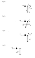
Die Beschreibung des REFERENZSTOSSVORGANGES wird auf zwei starre elastische massengleiche Körper bezogen, nämlich einen Körper B, bestehend aus einer Punktmasse und einen Rotorkörper R, bestehend aus zwei einander gleichen halb so großen Punktmassen Rx und Ry, die auf Distanz durch ein masseloses Stabelement zu einer symmetrischen Hantel mit der Drehachse im Schwerpunkt verbunden sind. Gemeinsamer Stoßort beider Körper ist die Berührung der Punkte B und RX, also zentrisch am Körper B und maximal exzentrisch am Körper R.The description of the REFERENCE JUMP is based on two rigid elastic masses of the same body, namely a body B, consisting of a point mass and a rotor body R, consisting of two equally equal half-size point masses R x and R y , which are spaced apart by a massless rod element a symmetrical dumbbell are connected to the axis of rotation in the center of gravity. Common shock location of both bodies is the touch of the points B and R X , so centric on the body B and at most eccentric on the body R.
Der Rotorkörper = Hantelrotor befindet sich in doppelter ebener Bewegung. Seine beiden Grundbewegungen Translation und Rotation erhielt er durch eine vorausgegangene Beschleunigung. Dementsprechend weist er einen translatorischen Grundimpuls p0 und einen rotatorischen Grundimpuls L0 auf. Rotatorische und translatorische Bewegung weisen gleichgroße kinetische Energie auf, der Impuls der einen Bewegung ist bei vollständiger Umwandlung bezogen auf konstante Masse dem Impuls der anderen Bewegung betragsgleich. Der Richtungssinn des Impulses p0 ist die Stoßrichtung.The rotor body = dumbbell rotor is in double plane motion. His two basic movements translation and rotation he received by a previous acceleration. Accordingly, it has a translational basic impulse p 0 and a basic rotatory impulse L 0 . Rotational and translational motion have equal kinetic energy, the momentum of one motion is at full conversion relative to constant mass equal to the momentum of the other motion. The sense of direction of the pulse p 0 is the direction of impact.
Beim Referenzstoßvorgang trifft der Hantelrotor R mit senkrechtem glattem exzentrischem Stoß auf den ruhenden Körper B und zwar für diesen Körper zentrisch. Beide Grundimpulse werden übertragen. In einem Stoßereignis vereint finden am gleichen Ort gleichzeitig zwei Teilstöße statt, die getrennt beschreibbar und gemeinsam zu bilanzieren sind. Der Teilstoß 1 ist der exzentrische Stoß der rotatorisch ruhenden Hantel aus translatorischer Bewegung heraus; der Teilstoß 2 ist der exzentrische Stoß der translatorisch ruhenden Hantel aus rotatorischer Bewegung heraus.During the reference shock process, the dumbbell rotor R strikes the resting body B with a vertical, smooth eccentric impact, specifically centrically for this body. Both basic pulses are transmitted. Combined in a shock event, two partial impacts take place at the same place, which are separately writable and to be balanced together. The
Beim Teilstoß 1 bleibt der translatorische Grundimpuls po auf beide Körper verteilt erhalten: p0 = pRt + pBt. Es entsteht aber der zusätzliche sekundäre rotatorische Impuls Lp der Rückwärtsdrehung im Hantelrotor, zu dem es keinen Gegenimpuls im Körper B gibt. Die Impulsbetragssumme wird um den Betrag Lp größer. Beim Teilstoß 2 ist der rotatorische Grundimpuls L0 der körperinterne Antagonist von Lp.In the
Es tritt somit beim gemeinsamen Doppelstoß - Ereignis beider Teilstöße im stoßenden Körper R gleichzeitig ein vorwärtsgerichteter und ein rückwärtsgerichteter rotatorischer Impuls auf. Ein derartiges Ereignis ist überhaupt nur für den Moment der Wechselwirkung möglich, denn antagonistische Impulse können nicht gleichzeitig im selben Körper Bestand haben. Sie können sich demzufolge auch nicht aufheben. Aus dem Betrag des zusätzlichen sekundären rotatorischen Impulses Lp entsteht ein betragsgleicher zusätzlicher sekundärer translatorischer Impuls Δp in Stoßrichtung im Körper B, zu dem es jetzt im Körper R keinen Gegenimpuls gibt. Die Beträge von Lp und Δp sind gleich, weil L0 größer als Lp ist. Zusätzlich wird der aus der Differenz der beiden rotatorischen Impulse verbleibende Rest L0(Rest)= L0 - Lp translatorisch gewandelt gegensinnig auf beide Körper verteilt: +pBr und -pRr. Für den Körper R ergibt sich damit ein Restimpuls pR.
Die Entstehung des zusätzlichen Impulses Δp entsprechend Lp ist ursächlich für die Vergrößerung der Impulsvektorsumme.Thus, in the joint double-collision event of both partial collisions in the colliding body R, a forward-directed and a backward-directed rotational impulse occur simultaneously. Such an event is possible only for the moment of interaction, because antagonistic impulses can not exist in the same body at the same time. As a result, they can not pick up. From the amount of additional secondary rotational momentum Lp, an equal amount of additional secondary translational pulse Δp is produced in the direction of impact in body B, to which there is now no counter-pulse in body R. The magnitudes of Lp and Δp are equal because L 0 is greater than Lp. In addition, the remainder L 0 (remainder) = L 0 -L p remaining from the difference of the two rotatory impulses is translated in opposite directions to both bodies: + p Br and -p Rr . For the body R, this results in a residual impulse p R.
The generation of the additional pulse Δp corresponding to Lp is the cause of the increase of the pulse vector sum.
Während sich die Impulsvektorsumme erhöht, verringert sich die Impulsbetragssumme in der Bilanz des Referenzstoßvorganges.
Somit wird nicht nur der Betrag des rotatorischen Grundimpulses L0 nicht gleichmäßig, vielmehr asymmetrisch auf die am Referenzstoßvorgang beteiligten Körper übertragen, sondern es verändert sich auch die Impulsvektorsumme losgelöst von der Impulsbetragssumme.As the pulse vector sum increases, the sum of the pulse sum in the balance of the reference shock process decreases.
Thus, not only the amount of the basic rotary pulse L 0 is transmitted not uniformly, but asymmetrically to the body involved in the reference shock process, but it also changes the momentum vector sum detached from the sum of momentum.
Die Impulsvektorsumme nach dem Referenzstoßvorgang ist eine andere als vorher. Das ist die Voraussetzung für eine systembezogene Vektorimpulsasymmetrie.The pulse vector sum after the reference shock process is different from before. This is the prerequisite for a system-related vector impulse asymmetry.
Wie groß unter anderen Bedingungen als denen des Referenzstoßvorganges die translatorische Impulsverstärkung in Stoßrichtung ist, wie die relative Größe des Impulses Lp ist, hängt vom Massenträgheitsmoment des Rotorkörpers, vom Massenverhältnis zwischen beiden Körpern und vom abgestimmten Verhältnis beider Grundimpulse ab.The magnitude of the pulse momentum Lp under other conditions than those of the reference shock process depends on the mass moment of inertia of the rotor body, the mass ratio between the two bodies, and the tuned ratio of the two fundamental pulses.
Der Referenzstoßvorgang wird anhand der beigefügten
- Fig. 1a
- die Ausgangssituation,
- Fig. 1 b
- den translatorischen Teilstoß,
- Fig. 1c
- den rotatorischen Teilstoß und
- Fig. 1d
- das Ergebnis des Zusammenwirkens beider Teilstöße darstellt.
- Fig. 1a
- The starting point,
- Fig. 1 b
- the translational partial impact,
- Fig. 1c
- the rotary partial thrust and
- Fig. 1d
- represents the result of the interaction of both partial impacts.
Beim STANDARDMODELL besteht das System aus vier Körpern: einem hohlen unelastischen Hüllkörper COV geringer, aber nicht vernachlässigbarer, Masse, der das System räumlich abschließt und drei in einer Ebene frei beweglichen elastischen Körpern in seinem Inneren. Der prismenförmige Hüllkörper weist spiegelbildliche senkrechte Seitenflächen auf. Die elastischen Körper sind die zwei Körper R und B aus der Referenzstoßbetrachtung und ein weiterer Körper Ba, der dem Körper B, im weiteren als Körper Bb bezeichnet, gleicht. Diese drei Körper befinden sich einander benachbart nahe dem Systemzentrum, wobei R zwischen Ba und Bb positioniert ist.In the STANDARD MODEL, the system consists of four bodies: a hollow inelastic envelope COV smaller but not negligible, mass closing off the system spatially and three elastic bodies freely moving in one plane inside it. The prism-shaped enveloping body has mirror-symmetrical vertical side surfaces. The elastic bodies are the two bodies R and B from the reference shock observation and another body B a , which is the body B, hereinafter referred to as the body B b , is similar. These three bodies are adjacent to each other near the system center, where R is positioned between B a and B b .
Das System habe einen relativen Massengrößenwert von näherungsweise = 3, welcher sich aus den relativen Teilmassen des Hüllkörpers mCOV > 0 und der elastischen Körper mBa = mBb = mR =1 zusammensetzt. Die Binnenbewegung der elastischen Körper bezieht sich auf den Hüllkörper, die Lage und Bewegung des allen vier Körpern gemeinsamen Massenschwerpunktes dagegen auf ein beliebiges äußeres Inertialsystem.The system has a relative mass size value of approximately = 3, which is composed of the relative masses of the enveloping body mCOV> 0 and the elastic body mB a = mB b = mR = 1. The internal movement of the elastic body refers to the enveloping body, the location and movement of all four bodies the common center of gravity, on the other hand, is an arbitrary external inertial system.
Für das System werden drei Bewegungszustände unterschieden: der Ausgangszustand innerer und äußerer Ruhe, der Zwischenzustand innerer Bewegung und äußerer Ruhe und der Endzustand innerer Ruhe und äußerer Bewegung. Zwischen Ausgangs- und Endzustand finden nacheinander Stöße zwischen allen vier Körpern statt.For the system, three states of motion are distinguished: the initial state of inner and outer rest, the intermediate state of inner movement and outer rest, and the final state of inner rest and outer movement. Between the initial and final states, bumps occur in succession between all four bodies.
Im Ausgangszustand liegen, wie später im Endzustand ebenfalls, die Punktmassen Ba, Bb und Rx parallel zur zentralen Längsachse des Systems = Systemachse. Die Radienachse des ruhenden Hantelrotors ist dazu senkrecht ausgerichtet. Die Systemachse trifft auf entgegengesetzte Hüllkörperflächen an den Zentralpunkten C1 und C2. Die Körper Ba und R sind kraftschlüssig eng, R und Bb dagegen auf Distanz benachbart. Den Ausgangszustand beendet ein Kraftstoß Ft = elastischer Stoß 1 zwischen den ruhenden Körpern Ba und R an den Punkten Ba und Rx1, der beide Körper beschleunigt und mit gleich großem translatorischem Impuls voneinander wegbewegt und dabei der Hantelrotor R zusätzlich in Drehung versetzt. Der Punkt Rx1 befindet sich etwas weniger exzentrisch auf dem Hantelrotor als die Punktmasse Rx, um für den Hantelrotor beim Kraftstoß Ft die beim Referenzstoßvorgang vorausgesetzte Energie- und Impulsverteilung auf beide Teilbewegungen zu bewirken.
Die translatorische Bewegungsrichtung des Hantelrotors ist die vorgesehene Antriebsrichtung.In the initial state, as later in the final state also, the point masses B a , B b and R x are parallel to the central longitudinal axis of the system = system axis. The radius axis of the stationary dumbbell rotor is aligned perpendicular thereto. The system axis meets opposite enveloping body surfaces at the central points C1 and C2. The bodies B a and R are frictionally tight, while R and B b are adjacent at a distance. The initial state is terminated by an impulse of force Ft =
The translational movement direction of the dumbbell rotor is the intended drive direction.
Nach längenmäßig abgestimmter gerader Bahnbewegung tritt der Hantelrotor R in den Referenzstoßvorgang = elastischer Stoß 2 = Doppelstoß ein. Unter den gewählten Bedingungen danach rotatorisch weitgehend zur Ruhe gekommen, bewegt sich der Hantelrotor aber translatorisch in gleichem Richtungssinn wie der durch ihn beschleunigte Körper Bb weiter, wenn auch mit anderem Impuls und mit anderer Geschwindigkeit. Die drei Körper Ba, Bb und R haben die ungleich großen translatorischen Impulse pa, pb und PR erhalten. Am größten ist der Impuls pb. Die Impulse pR und pb wirken in Antriebsrichtung, der Impuls pa ihnen entgegen.After lengthwise tuned straight web movement of the dumbbell R enters the reference shock process =
Mit dem Auftreffen des Körpers Ba im Punkt C1 und des Körpers Bb im Punkt C2 auf den Hüllkörper = unelastische Stöße 3 und 4 und dem dortigen Verharren in systembezogener Ruhe werden die antagonistischen Impulse pa und pb auf den Hüllkörper übertragen. Ihre Summe ergibt den resultierenden translatorischen Nettoimpuls pcomp. Er beschreibt die aus gemeinsamer Beschleunigung hervorgehende Bewegungsänderung der Körper Ba, Bb und COV in Antriebsrichtung.With the impact of the body B a at point C1 and the body B b at point C2 on the envelope =
Aufgrund seiner geringeren Geschwindigkeit als derjenigen des ihm vorauseilenden Körpers Bb und seiner höheren Geschwindigkeit als derjenigen des Körperverbundes COV/Ba/Bb trifft auch der Körper R zeitversetzt am Ort C2 auf den unelastischen Hüllkörper COV auf, wo er verharrt. Die vier Körper des Systems befinden sich im stabilen formschlüssigen Verbund.Due to its lower speed than that of the leading body B b and its higher speed than that of the body group COV / B a / B b , the body R also strikes time-displaced at location C2 on the inelastic envelope COV, where it remains. The four bodies of the system are in stable positive connection.
Damit ist der Endzustand des Systems eingetreten: in gegenseitiger Ruhestellung bewegen sich alle vier Körper über ihren gemeinsamen Masseschwerpunkt vereint mit gleicher Geschwindigkeit in gleicher Richtung gegen das Inertialsystem weiter. Die Bewegungsänderung des Systems ist beschrieben durch Δpsystem = pcomp+ pR Thus, the final state of the system has occurred: in mutual rest position, all four bodies move on their common center of mass united at the same speed in the same direction against the inertial system on. The change of motion of the system is described by Δp system = p comp + p R
Die Gesamtimpulsvektorsumme des Systems ist gestiegen.The total impulse vector sum of the system has increased.
Der Kraftstoß Ft = elastischer Stoß 1 fand am zentrumsnahen Ort S1 statt, der elastische Stoß am Ort S2. Der Hantelrotor R bewegt sich im Streckenabschnitt S1/C2, der Körper Ba im Streckenabschnitt S1/C1 und der Körper Bb im Streckenabschnitt S2/C2. Mit dem Eintreten des Endzustandes ist eine Bewegungsabfolge beendet und deren Impulsbilanzierung abgeschlossen.The force impact Ft =
Andere Kräfte als der Kraftstoß Ft führen die drei elastischen Körper unter Vermeidung jedweder Winkelbeschleunigung gleichförmig geradlinig zu ihrem Bewegungsursprung zurück und versetzen das System vom Endzustand in einen neuen inneren Anfangszustand.Other forces than the force Ft, while avoiding any angular acceleration, smoothly return the three elastic bodies to their origin of motion in a straight line, and move the system from the final state to a new initial state.
Im Ergebnis des Übergangs vom inneren Anfangs- zum inneren Endzustand erfährt das System eine äußere Beschleunigung. Während des Überganges vom inneren Endzustand zum inneren Anfangszustand verharrt es in gleichförmiger äußerer Bewegung.As a result of the transition from the inner initial to the inner final state, the system experiences an external acceleration. During the transition from the inner final state to the inner initial state, it remains in a uniform external motion.
Das Standardmodell des Systems wird anhand der beigefügten verknüpften
die
die
darstellen.The standard model of the system is linked by the attached
the
the
represent.
Vereinfachend wird für die Körper Ba und Bb an den Orten C1 und C2 ein identischer Stoßzeitpunkt angenommen. Am Ort C2 soll keine elastische Wechselwirkung zwischen den Körpern R und Bb stattfinden. Im Gegensatz zum Ausführungsmodell werden beim Standardmodell Folgen unvollkommener axialer Massensymmetrie und der leicht dezentralen Lage des Stoßortes C1 nicht weiter berücksichtigt.For simplicity, an identical shock time is assumed for the bodies B a and B b at the locations C1 and C2. At location C2 no elastic interaction between the bodies R and B b should take place. In contrast to the execution model, the consequences of imperfect axial mass symmetry and the slightly decentralized position of the impact location C1 are not considered further in the standard model.
Das dem Standardmodell zugrundeliegende Prinzip gilt auch unter realen ausführungstechnischen Anpassungen und Einschränkungen. Diese können die Lage des Ortes S1 für den elastischen Stoß 1 ebenso betreffen, wie die Veränderung der translatorischen Geschwindigkeiten nach dem elastischen Stoß 2, wie das Verhältnis der Impulse L0 und p0 am Hantelrotor, wie den Abstand der Stoßorte S1 und S2 und wie das Ersetzen senkrechter Stöße am Hantelrotor durch Stöße mit lediglich hinreichend steilem Auftreffwinkel. Dem Sinn der technischen Ausführung entspricht es, dass dann vor allem die Masse des Hüllkörpers groß wird.The underlying principle of the standard model also applies under real execution-technical adjustments and restrictions. These may concern the position of the location S1 for the
Mit jedem erneuten Verlassen eines erneuten Ausgangszustandes beginnt eine neue Impulsbilanzierungsebene. Im einmaligen wie im zyklisch wiederholten Vorgang wird durch das Wirken innerer Beschleunigungskräfte ein nach außen wirkender Antriebsimpuls "aus dem System auf das System" übertragen. Auf diese Weise ist die geradlinige Beschleunigung eines systemischen Verbundes von Körpern notwendigerweise unter Energiezufuhr, aber ohne Einwirkung eines systemfremden äußeren Kraftstoßes möglich. Durch eine starre und abgeschlossene Hülle tritt der Körperverbund bei gleichzeitiger Massenkonstanz gegenüber seiner Umgebung als ein Körper in Erscheinung.Each time a new output state is exited, a new pulse accounting level begins. In the single and in the cyclically repeated process, an external drive pulse is transmitted "from the system to the system" by the action of internal acceleration forces. In this way, the rectilinear acceleration of a systemic composite of bodies is necessarily possible with energy input, but without the influence of a foreign external impulse. Through a rigid and closed shell of the body composite appears at the same time as a body in mass constancy with respect to its environment.
Physikalisch kennzeichnend für das Prinzip ist die kinetische Wechselwirkung von Körpern in einem geschlossenen System, bei der in einem Körper zugleich zwei Trägheitsarten wirksam werden, bei der sich folglich zwischen den Körpern das Verhältnis ihrer trägen Massen vom Verhältnis ihrer wirkenden Trägheitskräfte unterscheidet, bei der es zu einer Stoßabfolge mit zweimaligem Wechsel unterschiedlicher Impulsarten und zweimaliger Wechselwirkungsbezogenheit von Massenträgheit und Massenträgheitsmoment beim Auftreten eines zusätzlichen inneren rotatorischen Zwischenimpulses kommt, bei der die Gesamtheit der Impulsübertragungen mit einer Vergrößerung der Impulsvektorsumme einhergeht und bei der sich daraus ein resultierender äußerer translatorischer Systemimpuls ergibt.Physically characteristic of the principle is the kinetic interaction of bodies in a closed system, in which two types of inertia take effect simultaneously in one body, in which the ratio of their inert masses differs between the bodies from the ratio of their acting inertial forces, at which a collision sequence with two changes of different pulse types and two times the interaction of inertia and moment of inertia occurs when an additional internal rotational intermediate pulse occurs, in which the total of the pulse transmissions is accompanied by an increase of the pulse vector sum and results in a resulting outer translational system pulse.
Das dem starren rotierenden Körper und seinem rotatorischen Zwischenimpuls zuzuordnende Massenträgheitsmoment wirkt gemäß den Stoßgesetzen bei der Entstehung der Drehbewegung translatorisch stoßkraftmindernd und bei deren Beendigung in gleicher Richtung stoßkraftverstärkend, wodurch der Unterschied der translatorischen Impulse gleichen Ursprungs begründet wird. Auf die experimentelle Evidenz dieses Effekts wird nochmals verwiesen.The mass moment of inertia attributable to the rigid rotating body and its rotational intermediate momentum acts in accordance with the laws of impact in the formation of rotational movement translationally impact force mitigating and at the termination in the same direction impact force enhancing, whereby the difference of translational pulses of the same origin is justified. The experimental evidence of this effect is again referred to.
Das aus Referenzstoßvorgang und Standardmodell abgeleitete erfindungsgemäße Antriebsprinzip mit dem Vermögen, unter Energiezufuhr einem autonomen Vehikel ohne Massenverlust in zyklischer taktförmiger Arbeitsweise beständig Antriebsimpulse zu verleihen, ist zusammenfassend in
Die GRUNDMERKMALE des erfindungsgemäßen Antriebsprinzips sind körper-, bewegungs-, raum-, prozess-, energie- und impulsbezogen folgende:
- 1. KÖRPERBEZOGEN ermöglichen nur starre Festkörper sowohl definierte Stöße an definierten Flächen, als auch Drehbewegungen unter Formwahrung, als auch das Wirksamwerden eines hohen Massenträgheitsmoments.
- 2. BEWEGUNGSBEZOGEN erfolgen in zyklischer Wiederholung tangentiale Auftreffstöße eines vorher beschleunigten freien Rotorkörpers gleichzeitig aus translatorischer und rotatorischer Bewegung heraus zentrisch auf einen ruhenden Körper unter Rotationsbeendigung und mit der Folge getrennter gleichsinniger translatorischer Weiterbewegung beider Körper bis zum Auftreffen auf eine Kammerwand.
- 3. RAUMBEZOGEN nehmen die gestoßenen Körper im Verlauf ihrer Antriebsbewegungen in zyklischer Wiederholung auf gemeinsamer zentraler gerader Bahn wechselnde Positionen ein und treten in Kontakt mit entgegengesetzten Kammerwänden.
- 4. PROZESSBEZOGEN erlauben translatorische Stoßabfolgen weniger Körper im geschlossenen Raum nur den diskontinuierlichen taktgemäßen Intervallbetrieb, bei dem sich der stetige Antriebsvorgang aus der Wiederholung identischer Antriebsereignisse ergibt.
- 5. ENERGIEBEZOGEN ist die Wandlung und Ableitung zugeführter kinetischer Energie je Stoßabfolge physikalisch nicht erforderlich, wohl aber technisch zur Ausführung eines zyklischen taktförmigen Antriebsvorganges geboten.
- 6. IMPULSBEZOGEN ergibt sich im System in jeder einem Antriebsereignis zugehörenden Stoßabfolge eine Vektorimpulsasymmetrie und daraus ein resultierender äußerer Antriebsimpuls.
- 1. BODY-RELATED only rigid solids allow defined shocks on defined surfaces, as well as rotational movements under preservation of form, as well as the effect of a high mass moment of inertia.
- 2. Moving in a cyclic repetition, tangential impingement impacts of a previously accelerated free rotor body take place concurrently out of a translational and rotational motion, concentrically on a stationary one Body under rotation termination and with the result of separate equidirectional translational movement of both bodies to impact on a chamber wall.
- 3. ROOM-RELATED, the butted bodies, in the course of their driving motions, undergo cyclical repetition on common central straight track changing positions and come into contact with opposite chamber walls.
- 4. PROCESS-RELATED translatory collision sequences allow fewer bodies in the closed space only the discontinuous cyclic interval operation, in which the continuous drive operation results from the repetition of identical drive events.
- 5. ENERGY-RELATED, the conversion and dissipation of supplied kinetic energy per impact sequence is not physically necessary, but it is technically necessary to carry out a cyclic, clock-type drive process.
- 6. PULSE-related results in the system in each pulse sequence belonging to a drive event, a vector pulse asymmetry and from this a resulting external drive pulse.
Erstens werden der Massenkonstanz und räumlichen Geschlossenheit wegen Antriebsbewegungen durch elektromagnetische Kräfte und nicht durch thermische Volumenkräfte aus Verbrennungsprozessen veranlasst und beschränken sich strikt auf die Antriebskammer.
Zweitens gehen für die zyklische Arbeitsweise alle Antriebsbewegungen vorübergehend in einen systembezogenen relativen Ruhezustand über und wechseln sich mit rückführenden Bereitstellungsbewegungen ab. Dafür tragen alle Auftreffstöße auf die Kammerwand unelastischen Charakter.
Drittens vereinen für einen hohen Wirkungsgrad die Rotoren betragsmäßig aufeinander abgestimmte translatorische und rotatorische Impulse auf sich und geben ihren Drall translatorisch gewandelt weiter, ohne dabei selbst in eine systembezogene Rückwärtsbewegung zu geraten. Dafür weisen sie ein hohes Massenträgheitsmoment auf und stehen im geeigneten Massenverhältnis zu ihren Stoßpartnern.
Viertens werden zur Vermeidung rotatorischer Systemimpulse an den betreffenden Antriebskammerwänden nur senkrechte zentrische Kräfte wirksam. Zudem sind alle bewegten Massen symmetrisch um die zentrale Antriebsachse verteilt und Rotoren spiegelbildlich doppelt ausgeführt mit einem gemeinsamen Massenschwerpunkt auf der zentralen Antriebsachse.
Fünftens wird für einen schwingungsarmen Betrieb unter den Bedingungen ständiger stoßförmiger Beschleunigungen die Antriebsleistung auf eine Anzahl gleichartiger Antriebselemente mit zeitlich versetztem Arbeitstakt verteilt.First, the mass constancy and spatial unity caused by motive movements by electromagnetic forces and not by thermal volume forces from combustion processes and are strictly limited to the drive chamber.
Secondly, for the cyclical operation, all drive movements temporarily transition to a system-related relative resting state and alternate with returning provisioning. For this all impact impacts on the chamber wall carry inelastic character.
Thirdly, for a high degree of efficiency, the rotors combine translational and rotational impulses that are coordinated with one another in terms of magnitude, and pass on their twist in a translational manner, without itself getting into a system-related backward movement. For this they have a high moment of inertia and are in a suitable mass ratio to their collision partners.
Fourth, only vertical centric forces are effective to prevent rotational system pulses at the respective drive chamber walls. In addition, all are Moving masses distributed symmetrically about the central drive axle and rotors mirror-image double executed with a common center of mass on the central drive axle.
Fifth, for a low-vibration operation under the conditions of constant shock-shaped accelerations, the drive power is distributed to a number of similar drive elements with a time-shifted power stroke.
Es ist Aufgabe der Erfindung, eine diesen Grundmerkmalen und Ausführungskonsequenzen folgende Antriebslösung bereitzustellen.
Dem folgt die allgemeine Ausführungsbeschreibung für jede erfindungsgemäße Antriebslösung und die ergänzende spezielle Ausführungsbeschreibung für eine technisch konkretisierte Antriebslösung.It is the object of the invention to provide a drive solution following these basic features and execution consequences.
This is followed by the general description of execution for each drive solution according to the invention and the supplementary special embodiment for a technically concretized drive solution.
Die ALLGEMEINE AUSFÜHRUNGSBESCHREIBUNG bezieht sich auf ein Antriebselement und ein Antriebsereignis. Das Antriebselement besteht aus der Antriebskammer, den in ihr befindlichen aktiven Körpern im Sinne des Standardmodells, der Antriebskammerwand und Funktionseinheiten, die dieser Kammerwand zugeordnet sind.The GENERAL EMBODIMENT relates to a drive element and a drive event. The drive element consists of the drive chamber, the active bodies contained in it in the sense of the standard model, the drive chamber wall and functional units which are assigned to this chamber wall.
In der Antriebskammer CHA kann der Ausgangsort der Antriebsbewegungen zentral oder peripher liegen. Bei zentraler Lage bewegen sich alle eingeschlossenen aktiven Körper RO/TR bilateral entgegengesetzt mit verschiedener Geschwindigkeit auf zwei gegenüberliegende Kammerwände COV zu. Es gibt zwei Übertragungskörper. Diese Ausführung bilateraler Stöße lehnt sich eng an das Standardmodell an. Liegt der Ausgangsort der Antriebsbewegungen dagegen peripher nur an der rückwärtigen Kammerwand, dann bewegen sich alle eingeschlossenen aktiven Körper in gleicher Richtung mit unterschiedlicher Geschwindigkeit auf die gegenüberliegende frontale Kammerwand zu . Diese Ausführung unilateraler Stöße modifiziert das Standardmodell. Das Massenverhältnis der wechselwirkenden Körper ist verändert, es gibt nur einen Übertragungskörper.In the drive chamber CHA, the starting point of the drive movements can be central or peripheral. At a central location, all trapped active bodies RO / TR move bilaterally in opposite directions at different rates to two opposite chamber walls COV. There are two transfer bodies. This type of bilateral impact is closely related to the standard model. On the other hand, if the starting point of the drive movements is peripherally only at the rearward chamber wall, then all the enclosed active bodies move in the same direction at different speeds towards the opposite frontal chamber wall. This type of unilateral impact modifies the standard model. The mass ratio of the interacting bodies is changed, there is only one transmission body.
Rotation und Translation eines Rotors können, wie im Standardmodell, aus gemeinsamer oder, alternativ, aus getrennter Kraftwirkung herrühren. Es ist also eine Ausführung mit einmaliger oder kombinierter Beschleunigung möglich. Ein erfindungsgemäßer Rotor kann weiterhin im Vollkreis oder auch nur im engen Kreissektor rotieren. Die Rotoren sind ideale Rotoren mit Ortsgleichheit von Drehachse und Massenschwerpunkt sowie mit peripherer Massenkonzentration. Sie können entweder als Kreisring oder als Hantel ausgeführt sein. Eine Hantel kann massengleiche Endkörper und identische Radien aufweisen oder massenungleiche Endkörper und ungleiche Radien.Rotation and translation of a rotor can, as in the standard model, be the result of common or, alternatively, separate force action. So it's one Execution with single or combined acceleration possible. An inventive rotor can continue to rotate in the full circle or even in the narrow circle sector. The rotors are ideal rotors with locality of rotation axis and center of gravity and with peripheral mass concentration. They can be designed either as a circular ring or as a dumbbell. A dumbbell may have masses of the same body and identical radii, or massless end bodies and unequal radii.
Die Antriebsbeschleunigung in der Antriebskammer soll entweder komprimiert in einem einmaligen Kraftstoß - Ereignis erfolgen oder über einen zeitlich gedehnten Kraftwirkungsvorgang. Der Kraftstoß wird vorzugsweise an einem Beschleunigungsort durch einen Elektromotor erzeugt und auf einen Hantelrotor ausgeübt. Die zeitlich gedehnte Kraftwirkung wird vorzugsweise entlang einer Beschleunigungsstrecke durch elektromagnetische Felder auf einen Ringrotor ausgeübt. Die erforderliche elektrische Energie für alle Vorgänge in der Antriebskammer ist vorhanden und wird dem Antriebselement zugeführt.The drive acceleration in the drive chamber should either be compressed in a single momentum event or via a time-expanded force action. The force pulse is preferably generated at an acceleration location by an electric motor and exerted on a dumbbell rotor. The temporally expanded force effect is preferably exerted along an acceleration path by electromagnetic fields on an annular rotor. The required electrical energy for all operations in the drive chamber is present and is supplied to the drive element.
Der zyklische Bewegungstakt aktiver Körper in der Antriebskammer unterscheidet zwei alternierend stattfindende Bewegungsvorgänge: ANTRIEBSBEWEGUNGEN als beschleunigte energiereiche Stoßbewegungen und nachfolgende gegengerichtete weggleiche BEREITSTELLUNGSBEWEGUNGEN als gleichförmige energieschwache Rückführungs- und Positionierbewegungen. Der Ausgangs - Ruhezustand der einen Bewegungen ist zugleich der Abschluss - Ruhezustand der anderen Bewegungen. Stöße innerhalb der Antriebskammer sind stets elastische Stöße, Auftreffstöße auf deren Wand stets unelastische Stöße.The cyclic moving stroke of active bodies in the drive chamber distinguishes between two alternating motions: DRIVE MOVEMENTS as accelerated high-energy jerking movements and subsequent counter-directional GTOPS as uniform energy-poor return and positioning movements. The initial idle state of one movement is at the same time the final state of rest of the other movements. Shocks within the drive chamber are always elastic shocks, impact impacts on the wall always inelastic collisions.
Aufgabe der Bereitstellungsbewegungen ist es, die am Antriebsgeschehen beteiligten Körper an den Ort, in die Position und in den Zustand zu versetzen, welche gemeinsam den Ausgangs - Ruhezustand der Antriebsbewegungen kennzeichnen. Alle aktiven Körper werden in ihren Ruhepositionen durch schwache lokale magnetische Kräfte fixiert. Alle Bewegungen sind ebene Bewegungen.
Sowohl die Orte der elastischen Stöße an den Rotoren als auch das Massenverhältnis der beteiligten Körper bestimmen die nach dem rotationsbeendenden elastischen Stoß verbleibende vorwärtsgerichtete translatorische Restbewegung der Rotoren und den "Wirkungsgrad" der Antriebsimpulserzeugung. Für die Ausführungsbeispiele wird, das Standardmodell weiter modifizierend, eine solcher Fall gewählt, dass alle Stoßkräfte maximal exzentrisch auf die Rotoren wirken und dass dafür die Masse jedes Übertragungskörpers kleiner ist als die beider Rotoren zusammen, dies jedoch bei radiengleichen hantelförmigen Rotoren nur in geringem Maße, bei radienungleichen hantelförmigen Rotoren dagegen in mehr als nur geringem Maße, vorzugsweise um die Hälfte. Weiterhin sind am Antriebsgeschehen aus Symmetriegründen mehrere Rotoren in gerader Anzahl beteiligt.The task of the provisioning movements is to move the bodies involved in the drive process to the location, into the position and into the state, which jointly characterize the initial resting state of the drive movements. All active bodies are fixed in their rest positions by weak local magnetic forces. All movements are plane movements.
Both the locations of the elastic shocks on the rotors and the mass ratio of the bodies involved determine the residual translational residual movement of the rotors remaining after the rotation-ending elastic impact "Efficiency" of drive pulse generation. For the embodiments, further modifying the standard model, such a case chosen that all impact forces act eccentric maximum on the rotors and that for the mass of each transmission body is smaller than the two rotors together, but this with radii-like dumbbell-shaped rotors only to a small extent, In radium-uneven dumbbell-shaped rotors, however, in more than a small extent, preferably by half. Furthermore, several rotors in an even number are involved in the drive process for reasons of symmetry.
Die SPEZIELLE AUSFÜHRUNGSBESCHREIBUNG bezieht sich nachfolgend auf die Herbeiführung eines Antriebsereignisses, gekennzeichnet durch unilaterale Stöße, durch einmalige Beschleunigung und durch Beschleunigung mittels eines Kraftstoßes.
Die ANTRIEBSKAMMERWAND COV ist starr, geschlossen und wärmeleitend. Mit dem Vehikel fest verbunden, erfolgt über sie die Weitergabe des Antriebsimpulses. Unerwünschte, aber unvermeidbare Prozesswärme aus dem Kammerinneren wird über sie nach außen übertragen und durch Konvektion oder Wärmestrahlung abgegeben. An ihrer Innenseite sind die der Antriebskammer zugehörigen Schienen 4 verankert. Die zur Antriebsrichtung parallelen Kammerwandbereiche sind die Seitenwände, die beiden dazu senkrechten stirnseitigen Bereiche sind in Antriebsrichtung die frontale Kammerwand und in entgegengesetzter Richtung die rückwärtige Kammerwand.The SPECIFIC EMBODIMENT below refers to the generation of a driving event characterized by unilateral shocks, one-off acceleration, and acceleration by means of an impulse of force.
The DRIVING CHAMBER WALL COV is rigid, closed and thermally conductive. Firmly connected to the vehicle, it passes on the transmission of the drive pulse. Undesirable but unavoidable process heat from the interior of the chamber is transmitted to the outside and released by convection or thermal radiation. On the inside of the drive chamber associated
An der rückwärtigen Kammerwand befindet sich der elektrische Antriebsmotor = Hauptmotor 2, an der frontalen Kammerwand mehrere symmetrisch angeordnete Stoßfangvorrichtungen 5. Der Hauptmotor verrichtet Spannungsarbeit an einer Antriebsfeder, aus deren Entspannung der Kraftstoß auf die aktiven Körper in der Antriebskammer hervorgeht. Ausgeübt wird der Kraftstoß durch den von der rückwärtigen Kammerwand ins Kammerinnere vorschnellenden Stößel 6.On the rear chamber wall is the electric drive motor =
Die Stoßfangvorrichtungen an der frontalen Kammerwand wirken als Bremszone, die einem auftreffenden aktiven Körper eine ausreichende Eindringtiefe ermöglichen, einen vollkommen unelastischen Stoß hervorbringen und auftreffende Körper an die Kammerwand binden. Ohne Einfluss auf die Impulsbilanz wird dabei kinetische Energie in nichtkinetische Energie umgewandelt. Das kann beispielsweise durch Reibung zwischen starren Körpern, reversible Verformung eines kissenförmigen plastischen Körpers oder Strömungserzeugung mittels Kolbendruck in einer Flüssigkeit erfolgen. Für jeden auf die frontale Kammerwand auftreffenden Körper ist eine eigene Stoßfangvorrichtung ausgeführt.The bumper devices on the frontal chamber wall act as a braking zone, allowing an impinging active body sufficient depth of penetration, producing a totally inelastic impact, and binding impacting bodies against the chamber wall. Without influencing the momentum balance, kinetic energy is converted into non-kinetic energy. This can be achieved, for example, by friction between rigid bodies, reversible deformation of a pillow-shaped plastic Body or flow generation by means of piston pressure in a liquid. For each striking the frontal chamber wall body has its own bumper is executed.
In der ANTRIEBSKAMMER CHA befinden sich zwei aktive Körper, nämlich der Rotor - Antriebskörper RO und der Übertragungskörper TR, weiterhin Schienen 4 zur Bewegungsführung beider Körper und außerdem vier Elektromotoren = Nebenmotoren zur Ausführung der Bereitstellungsbewegungen, davon einer in den Übertragungskörper integriert und drei in den Rotor - Antriebskörper integriert. Die Antriebskammer weist eine wärmeleitende Gasatmosphäre auf. Die Stromzufuhr für die vier Nebenmotoren erfolgt über die Schienen.
Die Zentralachse der Antriebskammer entspricht der gemeinsamen translatorischen Bewegungsbahn von Rotor - Antriebskörper und Übertragungskörper. Die Massenschwerpunkte beider Körper bewegen sich nur auf der Zentralachse. Da alle Kräfte auf stirnseitige Kammerwände senkrecht zentrisch wirken und auf die Seitenwände keine Kräfte wirken, sind seitliche Beschleunigungskräfte mit Rotationskonsequenz für das System ausgeschlossen. Der Kraftstoß an der rückwärtigen Kammerwand trifft nur den Rotor - Antriebskörper. Auftreffstöße auf die frontale Kammerwand erfolgen vorzugsweise durch beide Körper getrennt. Zwischengelagert ist der Stoß des Rotor - Antriebskörpers auf den Übertragungskörper.In the CHA CHA are two active bodies, namely the rotor drive body RO and the transfer body TR, further rails 4 for moving both bodies and also four electric motors = auxiliary motors for carrying out the supply movements, one of which integrated into the transfer body and three in the rotor - Drive body integrated. The drive chamber has a heat-conducting gas atmosphere. The power supply for the four auxiliary motors via the rails.
The central axis of the drive chamber corresponds to the common translational trajectory of rotor - drive body and transmission body. The centers of mass of both bodies move only on the central axis. Since all forces act on the end-side chamber walls vertically centric and no forces act on the side walls, lateral acceleration forces are excluded with rotation consequence for the system. The force impact on the rearward chamber wall hits only the rotor - drive body. Impact impacts on the frontal chamber wall are preferably carried out by both bodies separately. Interposed is the impact of the rotor - drive body on the transfer body.
Rotor - Antriebskörper und Übertragungskörper bewegen sich hintereinander platziert über eigene Radachsen als Wagen nach dem Schiene - Rad - Prinzip frei in einem gemeinsamen geraden Korridor, dabei zweidimensional geführt durch mehrere gegenüberliegende Schienen. Ihre Antriebsbewegungen gehen weitgehend reibungsfrei vonstatten.Rotor - drive body and transmission body move one behind the other via their own wheel axles as carriages according to the rail - wheel principle freely in a common straight corridor, guided in two dimensions by several opposing rails. Your drive movements are largely frictionless.
Zu Beginn der Antriebsbewegungen befindet sich der Rotor - Antriebskörper in Kontakt mit dem Stößel, der Übertragungskörper aber auf geringer Distanz zum Rotor - Antriebskörper. Diese Distanz hat mindestens den Betrag der Stößelauslenkung, also der Beschleunigungsstrecke der Rotoren, und höchstens den Betrag, ab dem der Auftreffstoßwinkel der Rotoren stärker von den Gegebenheiten des senkrechten Stoßes abweichen würde als ihr Abstoßwinkel.At the beginning of the drive movements, the rotor drive body is in contact with the plunger, but the transfer body is at a short distance from the rotor drive body. This distance has at least the amount of ram deflection, ie the acceleration distance of the rotors, and at most the amount from which the impact angle of the rotors would deviate more strongly from the conditions of the vertical impact than their repulsion angle.
Während alle Massenschwerpunkte der bewegten Körper auf gemeinsamer Ebene liegen, sind die jeweils räumlich angeordneten und an den Antriebskammerwänden befindlichen Führungsschienen für Rotor - Antriebskörper und Übertragungskörper ebenenversetzt vorzugsweise an unterschiedlichen gegenüberliegenden Wänden ausgeführt. Trotz des gemeinsamen Bewegungskorridors wird dadurch die Kollision eines Körpers mit dem Fahrwerk des anderen Körpers und werden andere als die erfindungsgemäßen Impulsübertragungen ausgeschlossen.
Rotor - Antriebskörper und Übertragungskörper sind keine monolithischen Körper, sondern entsprechen technisch üblichen rollenden Fahrzeugen mit der Fähigkeit zum Eigenantrieb. In Antriebsrichtung rollen sie passiv geschossähnlich ungebremst bis zum Stoß, in Gegenrichtung wirkt ihr eigener Elektromotor auf ihre Radachse und bewirkt ein herbeigeführter antriebswirksamer Kraftschluss zu den Schienen die erfindungsgemäße Bereitstellungsbewegung. Mit Abschluss der Bereitstellungsbewegung enden Eigenantrieb und dieser Schienen - Kraftschluss wieder.While all the centers of gravity of the moving bodies lie on a common plane, the guide rails for the rotor drive body and the transmission body, which are spatially arranged and located on the drive chamber walls, are embodied offset in planes, preferably on different opposite walls. Despite the common motion corridor thereby the collision of a body with the chassis of the other body and other than the pulse transmissions according to the invention are excluded.
Rotor - Drive body and transmission body are not monolithic body, but correspond to technically usual rolling vehicles with the ability to self-propelled. In the drive direction, they passively passively shoot unbraked to the point of impact, in the opposite direction their own electric motor acts on their wheel axle and causes a drive-driven frictional connection to the rails which brings about the provisioning movement according to the invention. Upon completion of the deployment movement self propelled and this rails - traction end again.
Der ROTOR - ANTRIEBSKÖRPER RO weist neben seinem Fahrwerk noch zwei identische hantelförmige Rotoren 1 auf, deren hinreichend großer Radius eine Auslenkung über die Fahrwerksgrenzen hinaus selbst bei geringem Drehwinkel ermöglicht. Beide Rotoren sind spiegelbildlich übereinander oder vorzugsweise nebeneinander angeordnet und befolgen dabei die generelle Massenverteilungssymmetrie um die Antriebsachse. Die Masse der Rotoren dominiert diejenige des Rotor - Antriebskörpers. Die Endkörper der hantelförmigen Rotoren sind prismenförmige Scheiben, deren plane Flächen parallel zur Bewegungsebene liegen.
Erfindungsgemäß ist ein hohes Massenträgheitsmoment der Rotoren des Rotor - Antriebskörpers. Im speziellen Anwendungsbeispiel kommen hantelförmige Rotoren mit einem Radien- und Endmassenverhältnis von 2 : 1 und der kleineren Endmasse am Stoßort zur Anwendung. Die Rotoren drehen sich aufgrund spiegelbildlicher Position gegensinnig, weisen also am Stoßort richtungsgleiche Kraftvektoren auf. Aufgrund ihrer Identität drehen sie sich zudem synchron. Die periphere Stoßflächengeometrie ist so ausgelegt, dass für beide Rotoren am jeweils gleichen Ort ein gemeinsamer exzentrischer Stoß stattfindet.In addition to its chassis, the ROTOR DRIVE BODY RO also has two identical dumbbell-shaped
According to the invention, a high mass moment of inertia of the rotors of the rotor drive body. In the specific application example dumbbell-shaped rotors are used with a radius and final mass ratio of 2: 1 and the smaller final mass at the impact location. The rotors rotate in opposite directions due to a mirror image position, ie have directional force vectors at the impact location. Because of their identity, they also turn in sync. The peripheral abutment geometry is designed so that a common eccentric impact occurs at the same location for both rotors.
Beide die Antriebsbewegung betreffenden Stöße, an denen der Rotor - Antriebskörper mit einer Doppelbewegung beteiligt ist, erfolgen nur über seine Rotoren. Zwischen den beiden Stößen drehen sich die Rotoren und bewegt sich der Rotor - Antriebskörper translatorisch schnell auf der kurzen Strecke bis zum Übertragungskörper. Die Kürze dieser Rollstrecke hält auch die gleichzeitige Winkelbewegung der Rotoren gering, vorzugsweise auf unter 30° begrenzt. Dadurch weisen beide Stöße an den Rotoren keine große Abweichung von der Eigenschaft des tangentialen, den Radius senkrecht treffenden Stoßes, auf. So werden bei beiden Stößen tatsächlich große rotatorische Impulsanteile wirksam mit der erfindungsgemäßen Folge für die geforderte translatorische Impulsverteilung.Both impacts concerning the drive movement, in which the rotor - drive body is involved with a double movement, take place only via its rotors. Between The rotors rotate in both joints and the rotor - drive body moves translationally fast over the short distance to the transmission body. The shortness of this rolling track also keeps the simultaneous angular movement of the rotors low, preferably limited to less than 30 °. As a result, both impacts on the rotors do not show any great deviation from the property of the tangential impact which hits the radius perpendicularly. Thus, in both collisions, large rotational momentum components actually become effective with the sequence according to the invention for the required translational momentum distribution.
Die Doppelausführung der Rotoren dient dem Ausschluss von Nebenimpulsen der Seitenauslenkung. Nach dem vorzugsweise rotationsbeendenden Stoß auf den Übertragungskörper bewegt sich der Rotor - Antriebskörper deutlich verlangsamt noch translatorisch weiter, bis er, wie vorher schon der ihm vorausgeeilte Übertragungskörper, auf die frontale Antriebskammerwand und seine Stoßfangvorrichtungen auftrifft. Dieser Auftreffstoß erfolgt über seitlich an seinem Fahrwerk vorbei vorkragende identische Stoßwangen 3, die ihrerseits symmetrisch zur Beschleunigungsachse angeordnet sind und eine Kraftübertragung im Sinne des zentrischen Stoßes auf die Kammerwand bewirken.The double version of the rotors serves to exclude secondary impulses of the side deflection. After the preferably rotation-ending impact on the transfer body, the rotor-drive body moves significantly slower translationally until it, as before the voreileilte him transfer body, impinges on the front drive chamber wall and its bumper devices. This impact occurs via laterally protruding past his chassis
Zwei der drei Elektromotoren des Rotor - Antriebskörpers dienen der Ausführung der rotatorischen Bereitstellungsbewegung jedes der beiden Rotoren. Ansetzend an deren Drehachse werden durch sie die Rotoren gleichförmig bis zur Winkelposition beim Kraftstoß zurückgedreht und dort in Ruhestellung wieder freigegeben. Sollten nach Abschluss der Antriebsbewegungen noch geringe rotatorische Restbewegungen verblieben sein, werden sie vorher ebenfalls durch diese Elektromotoren beendet.Two of the three electric motors of the rotor drive body are used to carry out the rotational deployment movement of each of the two rotors. Attaching to the axis of rotation through them, the rotors are uniformly turned back to the angular position during power surge and released there in the rest position again. If, after completion of the drive movements, slight residual rotational movements remain, they are also terminated beforehand by these electric motors.
Der ÜBERTRAGUNGSKÖRPER TR ist starr und weist eine kompakte Form und hinreichender Masse auf und ist imstande, einen elastischen Stoß gegen seinen Massenschwerpunkt aufzunehmen und einen unelastischen Stoß aus diesem heraus abzugeben. Er weist eine plane Rückfläche für den näherungsweise senkrechten Stoß durch beide Rotoren auf und andererseits eine Frontalflächengeometrie, vorzugsweise in Form eines Sporns, die auf die Wahl der Bremskräfte abgestimmt ist. Aufgabe des Übertragungskörpers ist es, die rotatorischen Impulse aus dem Rotor - Antriebskörper vollständig als translatorischen Impuls aufzunehmen und zusammen mit dem ebenfalls erhaltenen größeren Teil von dessen translatorischem Impuls auf die frontale Antriebskammerwand zu übertragen.The TRANSMISSION BODY TR is rigid and has a compact shape and sufficient mass and is capable of absorbing an elastic shock against its center of mass and giving an inelastic shock therefrom. It has a flat rear surface for the approximately vertical impact by both rotors and on the other hand a frontal surface geometry, preferably in the form of a spur, which is tuned to the choice of braking forces. The task of the transfer body is to take up completely the rotatory impulses from the rotor - drive body as a translatory impulse and together with the same to receive transferred larger part of its translational pulse to the front drive chamber wall.
Die Impulsübertragungen zwischen Rotor - Antriebskörper, Übertragungskörper und Antriebskammerwand erfolgen dreistufig. In der ersten Stufe wird die Rotation der Rotoren vorzugsweise vollständig beendet, in der zweiten Stufe überträgt der Übertragungskörper den aus den Rotoren stammenden nunmehr translatorischen Impuls zusammen mit dem größeren Teil des übernommenen translatorischen Grundimpulses des Rotor - Antriebskörpers auf die Antriebskammerwand und in der dritten Stufe überträgt der Rotor - Antriebskörper seinen translatorischen Restimpuls auf dieselbe Antriebskammerwand. Dabei umgreift er den vor ihm bereits an der Kammerwand ruhenden Übertragungskörper berührungsfrei mit seinen Stoßwangen. Die Zweistufigkeit der translatorischen Impulsübertragung ist auch wirkungsgradbezogen günstig.The momentum transfer between rotor - drive body, transfer body and drive chamber wall takes place in three stages. In the first stage, the rotation of the rotors is preferably completed completely, in the second stage the transfer body transmits the now translational pulse originating from the rotors together with the greater part of the inherited translational basic momentum of the rotor drive body to the drive chamber wall and in the third stage the rotor - drive body its translational residual pulse on the same drive chamber wall. He surrounds the already resting on the chamber wall before him transfer body without contact with his bumper cheeks. The two-stage translational impulse transmission is also favorable in terms of efficiency.
Die Erfindung wird anhand der beigefügten
- Fig. 4
- die Ausführung mit zwei symmetrischen ring- oder hantelförmigen Rotoren und mit bilateralen Stößen, also einem zentralen Kraftstoßort bei zwei Übertragungskörpern zeigt,
- Fig. 5a
- die Ausführung mit zwei asymmetrischen hantelförmigen Rotoren und mit unilateralem Stoß, also dem Kraftstoßort an der Antriebskammerwand bei nur einem Übertragungskörper zeigt und dabei die Situation zu Beginn der Antriebsbewegungen wiedergibt und
- Fig. 5b
- die gleiche Ausführung wie
Fig. 5a zeigt, dabei jedoch die Situation am Ende der Antriebsbewegungen wiedergibt.
- Fig. 4
- the design with two symmetrical ring-shaped or dumbbell-shaped rotors and with bilateral impacts, ie a central force impact location in two transmission bodies,
- Fig. 5a
- the execution with two asymmetric dumbbell-shaped rotors and with unilateral shock, so the force impact location on the drive chamber wall with only one transmission body shows and reflects the situation at the beginning of the drive movements and
- Fig. 5b
- the same design as
Fig. 5a shows, but the situation at the end of the drive movements reflects.
Die Figuren beschränken sich auf wesentliche erfindungsgemäße Elemente und die Darstellung der Antriebsbewegungen. Verzichtet wird auf die Darstellung der Bereitstellungsbewegungen, der dafür erforderlichen Elektromotoren, der Hilfsmittel /Magnete zur Stabilisierung der Ruheposition der bewegten Körper und der versetzten Ebenen der Führungsschienen für Rotor-Antriebs- und Übertragungskörper. Die
- RR
- Rotorkörper = Hantelrotor im Modell des ReferenzstoßvorgangesRotor body = dumbbell rotor in the model of the reference shock process
- Rx, Ry R x , R y
- verbundene Punktmassen des Rotorkörpers Rconnected point masses of the rotor body R
- B, Ba, Bb B, B a , B b
- Punktmassenkörper des Referenzstoßvorganges / des StandardmodellsPoint mass body of the reference impact process / standard model
- +/- p+/- p
- translatorische Impulse mit Richtungssinn allgemeintranslational impulses with sense of direction in general
- P0, pRt, pRr, pR P 0 , p Rt , p Rr , p R
- translatorische Impulse des Rotorkörperstranslational impulses of the rotor body
- pa, pb, pBr, pBt, Δpp a , p b , p Br , p Bt , Δp
- translatorische Impulse der Punktmassenkörper B, Ba und Bb translational impulses of the point mass bodies B, B a and B b
- LL
- rotatorischer Impuls eines Körpers allgemeinRotatory impulse of a body in general
- L0, Lp, L0(Rest) L 0 , Lp, L 0 (rest)
- rotatorische Impulse des Rotorkörpers RRotatory impulses of the rotor body R
- mBa, mBb, mRmB a , mB b , mR
- Massen der Körper Ba, Bb, RMasses of bodies B a , B b , R
- COVCOV
- Hüllkörper des Standardmodells / AntriebskammerwandCovering body of the standard model / drive chamber wall
- FtFt
- auslösende Beschleunigungskraft / Kraftstoßtriggering acceleration force / power surge
- locS1locS1
- Ort des Kraftstoßes und Bewegungsbeginn innerhalb des SystemsPlace of impulse and start of movement within the system
- locS2locS2
- Ort des rotatorisch - translatorischen Doppelstoßes innerhalb des SystemsPlace of the rotational - translatory double thrust within the system
- locC1locC1
- zentraler rückwärtiger Hüllkörperort der Impulsübertragung entgegen der Antriebsrichtungcentral rearward envelope body location of the impulse transmission opposite to the drive direction
- locC2locC2
- zentraler frontaler Hüllkörperort der Impulsübertragung in Antriebsrichtungcentral frontal envelope body location of the momentum transfer in drive direction
- PCOV, Pcomp, Psystem P COV , P comp , P system
- translatorische Impulse des Hüllkörpers COV, des Körperverbundes Ba / Bb / COV und des Systems beim Standardmodelltranslational impulses of the envelope body COV, of the body group B a / B b / COV and of the system in the standard model
- CHACHA
- Antriebskammer, auch Systeminnenraum beim StandardmodellDrive chamber, also system interior in the standard model
- RORO
- Rotor - AntriebskörperRotor - drive body
- TRTR
- Übertragungskörpertransmission body
- 11
- Rotor des Rotor - AntriebskörpersRotor of the rotor - drive body
- 22
- Elektromotor zur Erzeugung der Antriebsbewegung = HauptmotorElectric motor for generating the drive movement = main motor
- 33
- Frontale Stoßwangen des Rotor - AntriebskörpersFrontal bumpers of the rotor - drive body
- 44
- Führungsschienen für Rotor - Antriebskörper und ÜbertragungskörperGuide rails for rotor - drive body and transmission body
- 55
- Bremszone / StoßfangvorrichtungBraking zone / bumper
- 66
- Stößel zur Vermittlung des KraftstoßesPestle to mediate the impulse of power
Claims (12)
wobei die Antriebsbewegungen dieser Körper in jedem Bewegungszyklus auf eine gemeinsame Startbeschleunigung zurückgehen, welche sich aus der Arbeit von einem oder mehreren Elektromotoren ergibt und für diese Körper zwei entgegengesetzte stetige Übertragungspfade translatorischer Impulse begründet neben der zusätzlichen Rotationsauslösung an einem dieser Körper,
wobei als Folge der Antriebsbewegungen dieser Körper ungleich große translatorische Impulse auf entgegengesetzte Kammerwände übertragen werden und somit auf das Vehikel insgesamt ein resultierender rein translatorischer Antriebsimpuls,
wobei diese Körper starre elastische Körper unterschiedlicher oder gleicher Masse sind, von denen einer als Rotor - Antriebskörper RO zur Ausführung der zusätzlichen Rotationsbewegung allein durch exzentrischen Stoß im Stande ist und von denen der oder die anderen Körper als Übertragungskörper TR Impulse vom Rotor - Antriebskörper aufnehmen und als translatorische Impulse auf eine Antriebskammerwand vermitteln,
wobei die Antriebsbewegung des Rotor - Antriebskörpers stets die Zwischenphase gleichzeitiger rotatorischer und translatorischer Bewegung enthält,
wobei jede Impulsübertragung vom Rotor - Antriebskörper auf einen vorzugsweise ruhenden Übertragungskörper aus seiner gleichzeitigen translatorischen und rotatorischen Bewegung heraus erfolgt, seine rotatorische Bewegung vollständig oder weitgehend beendet, seine translatorische Bewegung unter Richtungssinnwahrung bremst, vorzugsweise aber nicht beendet, und stets alle von ihm weitergegebenen Impulse rein translatorischer Natur sind,
wobei alle antriebsbewegungsbezogenen Wechselwirkungen zwischen Rotor - Antriebskörper, Übertragungskörpern und Antriebskammerwänden Stoßcharakter tragen, alle Stöße zwischen dem Rotor - Antriebskörper und einem Übertragungskörper weitestgehend elastische Stöße sind, dabei exzentrisch aus dem rotierenden Körper und zentrisch auf den Übertragungskörper, und alle Auftreffstöße auf eine Kammerwand unelastische zentrische Stöße sind,
wobei die Bereitstellungsbewegungen von Rotor - Antriebskörper und Übertragungskörpern nach dem Abschluss der Antriebsbewegungen beginnen, durch mehrere voneinander, unabhängige und auch nur ihrem Zustandekommen dienende Elektromotoren ausgeführt werden und im Wechsel mit den Antriebsbewegungen zur zyklischen Arbeitsweise des Antriebssystems führen,
wobei_die Entstehung des resultierenden Antriebsimpulses der Zuführung, dann aber keiner Wandlung und Ableitung kinetischer Energie bedarf, sondern allein Folge der zweimaligen Wechselwirkung zwischen gleichzeitig auftretenden unerschiedlichen Trägheitskräften einerseits und Beschleunigungskräften andererseits bei den beiden exzentrischen Stößen ist, welche am Rotor - Antriebskörper die rotatorische Zwischenbewegung auslösen und beenden,
wobei jegliche Wandlung kinetischer Energie beim unelastischen Auftreffstoß auf eine Antriebskammerwand nur zur Ausführung abgeschlossener Bewegungsintervalle und unbegrenzter zyklischer Arbeitsweise erforderlich ist.Electromechanical drive system, applicable to all drive purposes and vehicles, preferably for autonomous missiles, in which, as a result of the supply of electrical energy and thereby caused acceleration work in a closed against mass transfer drive chamber CA in cyclic interval operation at least two mutually and with drive chamber walls COV kinetically interacting solids with of their coordinated mass move freely along a defined planar translational path reversing direction in an infinite sequence of identical motion cycles and effecting external acceleration of the vehicle at the inner forces in the drive chamber, each motion cycle of these bodies having both accelerated, energetic, impulse balance influencing outward drive motions from the defined initial state, as well as this opposite, largely uniform, energy-weak, impulsb includes neutral-neutral provisioning movements back to the defined initial state, and relative system-related rest conditions occur between these movements,
wherein the motive movements of these bodies in each cycle of motion are due to a common starting acceleration resulting from the operation of one or more electric motors and for these bodies two opposite continuous transmission paths of translational impulses, besides the additional rotation release on one of these bodies,
wherein as a result of the driving movements of these bodies unequal translatory pulses are transmitted to opposite chamber walls and thus to the vehicle as a whole a resulting purely translational drive pulse,
these bodies are rigid elastic bodies of different or the same mass, one of which is capable of carrying out the additional rotational movement solely by eccentric shock as the rotor drive body RO and of which the other body or bodies receive as impulses TR transmission pulses from the rotor drive body and convey as translational impulses to a drive chamber wall,
wherein the drive movement of the rotor - drive body always contains the intermediate phase of simultaneous rotational and translational movement,
wherein each momentum transfer from the rotor - drive body to a preferably stationary transmission body from its simultaneous translational and rotational movement out, its rotational movement completely or largely stopped, slows its translational movement under Richtungssinn preservation, but preferably not ended, and always all imparted by him pulses pure are translational nature,
all drive - motion - related interactions between rotor - drive body, transmission bodies and drive chamber walls carry shock character, all shocks between the rotor - drive body and a transmission body are largely elastic shocks, eccentric from the rotating body and centric on the transmission body, and all impact impacts on a chamber wall inelastic centric Shocks are,
wherein the supply movements of rotor - drive body and transfer bodies begin after the completion of the drive movements, are performed by a plurality of mutually independent, independent and only their coming serving electric motors and lead in alternation with the drive movements to the cyclic operation of the drive system,
where_ the formation of the resulting drive pulse of the supply, but then no conversion and dissipation of kinetic energy is needed, but solely consequence of the two-time interaction between simultaneously occurring unequal inertial forces on the one hand and acceleration forces on the other hand in the two eccentric jolts, which trigger the rotatory intermediate motion on the rotor - drive body and break up,
any kinetic energy conversion is required in the inelastic impingement impact on a drive chamber wall only to complete completed movement intervals and unlimited cyclic operation.
wobei dieser Wagen seinerseits durch eigene Führungsschienen 4 an der Antriebskammerwand reibungsarm geführt wird, das vorzugsweise über ein Fahrwerk nach dem Schiene - Rad - Prinzip, und so gemeinsam mit den Rotoren die translatorische Bewegung des Rotor - Antriebskörpers vollzieht und
wobei für seinen Auftreffstoß auf die frontale Antriebskammerwand seitlich vorkragende Stoßwangen 3 ausgeführt sind.Electromechanical drive system according to claims 1 to 3, wherein the rotor - drive body RO consists of two form and mass identical ring- or dumbbell-shaped rotors 1, on which alone he receives the forces to carry out his drive movements, which are his sole impact mediator on a transmission body which rotate in opposite directions in synchrony, which transmit forces synchronously, which are located without contact on top of each other, but preferably on the same plane next to each other and which are connected via their axes of rotation with a car,
this car in turn is guided by its own guide rails 4 on the drive chamber wall friction, preferably via a chassis according to the rail - wheel principle, and so together with the rotors, the translational movement of the rotor - drive body accomplishes and
wherein for its impact on the frontal drive chamber wall laterally projecting thrust cheeks 3 are executed.
wobei an jedem Rotor Drehachse und Massenschwerpunkt identisch sind,
wobei_hantelförmige Rotoren auch asymmetrisch mit unterschiedlichen Radien und Endmassen ausgeführt sein können und
wobei in diesem Fall der Stoßort des Rotors am schwerpunktfernen Rotorende liegt.Electromechanical drive system according to claims 1 and 5, in which each rotor 1 has a high mass moment of inertia, is mass-rich compared to the Carriage of the rotor - drive body and has on its periphery suitable for the eccentric vertical impact surfaces,
where the rotation axis and center of gravity are identical on each rotor,
which dumbbell-shaped rotors can also be designed asymmetrically with different radii and end masses and
in which case the impact location of the rotor is at the center of the distal rotor end.
wobei die translatorische Gegenbeschleunigung stets auf die rückwärtige Antriebskammerwand oder einen in deren Richtung gelegenen benachbarten Übertragungskörper wirkt,
wobei_die alleinige Kraftquelle bei gemeinsamer Kraftübertragung oder die anteilige Kraftquelle für die nur translatorische Beschleunigung bei getrennter Kraftübertragung ein Elektromotor oder mehrere Elektromotoren = Hauptmotoren 2 sind, die entweder die Federspannung für vorzugsweise einen kraftstoßübertragenden Stößel erzeugen oder die ein linear beschleunigendes elektromagnetisches Kraftfeld erzeugen,
wobei_sich diese Elektromotoren am Ort der Kraftwirkung befinden, entweder an der rückwärtigen Antriebskammerwand oder in einem rückwärtigen Übertragungskörper oder in den Rotoren selbst und
wobei sich bei getrennter Kraftübertragung die beiden Rotoren allein durch gegenseitige Beschleunigung über dann zusätzliche, vorzugsweise auf die Drehachsen wirkende Elektromotoren in ihre Rotation versetzen.Electromechanical drive system according to claims 1 to 6, in which the starting acceleration for the translational drive movement of the rotor drive body and for the rotary drive movement of its rotors originates from joint or separate transmission, but in any case is completed before the subsequent impact impact,
wherein the translational counter acceleration always acts on the rear drive chamber wall or an adjacent transfer body located in the direction thereof,
wherein the sole power source in the case of joint transmission or the proportional power source for the only translational acceleration with separate power transmission is one or more electric motors = main motors 2 which either generate the spring tension for a thrust transmitting ram or which produce a linearly accelerating electromagnetic force field,
These electric motors are located at the location of the force action, either on the rear drive chamber wall or in a rear transfer body or in the rotors themselves and
with separate power transmission, the two rotors alone by mutual acceleration on then additional, preferably acting on the axes of rotation electric motors in their rotation.
Priority Applications (1)
| Application Number | Priority Date | Filing Date | Title |
|---|---|---|---|
| EP07150051A EP2072816A1 (en) | 2007-12-17 | 2007-12-17 | Drive system using mechanical impulse conversion, preferably for missiles |
Applications Claiming Priority (1)
| Application Number | Priority Date | Filing Date | Title |
|---|---|---|---|
| EP07150051A EP2072816A1 (en) | 2007-12-17 | 2007-12-17 | Drive system using mechanical impulse conversion, preferably for missiles |
Publications (1)
| Publication Number | Publication Date |
|---|---|
| EP2072816A1 true EP2072816A1 (en) | 2009-06-24 |
Family
ID=39540219
Family Applications (1)
| Application Number | Title | Priority Date | Filing Date |
|---|---|---|---|
| EP07150051A Withdrawn EP2072816A1 (en) | 2007-12-17 | 2007-12-17 | Drive system using mechanical impulse conversion, preferably for missiles |
Country Status (1)
| Country | Link |
|---|---|
| EP (1) | EP2072816A1 (en) |
Cited By (1)
| Publication number | Priority date | Publication date | Assignee | Title |
|---|---|---|---|---|
| CN113359819A (en) * | 2021-05-27 | 2021-09-07 | 北京航空航天大学 | Optimal guidance law with collision angle constraint and acceleration limitation |
Citations (4)
| Publication number | Priority date | Publication date | Assignee | Title |
|---|---|---|---|---|
| DE19909766A1 (en) * | 1999-03-05 | 1999-09-30 | Georges Bourbaki | Space craft drive mechanism |
| US6259177B1 (en) * | 2000-06-30 | 2001-07-10 | David Deschamplain | Motion imparting system |
| WO2001055592A1 (en) | 2000-01-25 | 2001-08-02 | Kim Sung Hun | Centrifugal propulsion system |
| WO2002063185A1 (en) * | 2001-01-08 | 2002-08-15 | Lim, Ah, How | Bi-directional to unidirectional torque conversion method and apparatus |
-
2007
- 2007-12-17 EP EP07150051A patent/EP2072816A1/en not_active Withdrawn
Patent Citations (4)
| Publication number | Priority date | Publication date | Assignee | Title |
|---|---|---|---|---|
| DE19909766A1 (en) * | 1999-03-05 | 1999-09-30 | Georges Bourbaki | Space craft drive mechanism |
| WO2001055592A1 (en) | 2000-01-25 | 2001-08-02 | Kim Sung Hun | Centrifugal propulsion system |
| US6259177B1 (en) * | 2000-06-30 | 2001-07-10 | David Deschamplain | Motion imparting system |
| WO2002063185A1 (en) * | 2001-01-08 | 2002-08-15 | Lim, Ah, How | Bi-directional to unidirectional torque conversion method and apparatus |
Cited By (2)
| Publication number | Priority date | Publication date | Assignee | Title |
|---|---|---|---|---|
| CN113359819A (en) * | 2021-05-27 | 2021-09-07 | 北京航空航天大学 | Optimal guidance law with collision angle constraint and acceleration limitation |
| CN113359819B (en) * | 2021-05-27 | 2024-04-16 | 北京航空航天大学 | Optimal guidance law with collision angle constraint and acceleration limitation |
Similar Documents
| Publication | Publication Date | Title |
|---|---|---|
| DE2936883A1 (en) | COMPETITION FIREARMS, ESPECIALLY BULLET-FREE AIR RIFLE OR HAND FIREARMS | |
| EP2072816A1 (en) | Drive system using mechanical impulse conversion, preferably for missiles | |
| EP1707809B1 (en) | Rotational inertial motor | |
| DE102014218023A1 (en) | Grounding arrangement for a vehicle | |
| DE102007023966B4 (en) | Light gas gun and method for accelerating a solid object by means of such a light gas gun | |
| DE102020007890B4 (en) | Propulsion device for a spacecraft | |
| EP1894842B1 (en) | Impulse propulsion system suitable for space travel with powered thrust generation without mass discharge | |
| WO2008089753A2 (en) | Momentum absorbing drive unit | |
| DE3742904A1 (en) | Drive apparatus | |
| DE697256C (en) | Recoil loader with sliding barrel and locked breech | |
| DE102009023478A1 (en) | Drive for vehicle i.e. spacecraft, has mobile mass bodies evenly implemented and shifted in movement in effective region of rigid mass body such that masses of mobile mass bodies are changed, where rigid mass body is rigid against vehicle | |
| DE4010758A1 (en) | Space vehicle propulsion procedure - using power source to accelerate masses which with collision and friction forks, provide forward drive | |
| DE4315943A1 (en) | Drive device having rotors and with translation in the angle gamma | |
| DE102017127650A1 (en) | Free piston device and method for operating a free piston device | |
| DE10241724B4 (en) | Electrogenerative ignition device for an explosive device | |
| DE19818580A1 (en) | Gas generator to create rapid electrical energy pulse to ignite gas burner | |
| DE4114910A1 (en) | Drive unit for space vehicle - has double catapult for discharging equal masses in direction of opposing bases of drive housing | |
| DE2061914A1 (en) | Device for accelerating and braking vehicles, in particular spacecraft | |
| DE102012103618B4 (en) | Gas powered firearm device with magnetic force accelerated balance mass | |
| DE102023001488A1 (en) | Nuclear fusion reactor | |
| DE3604406A1 (en) | Inertial drive | |
| DE102021126232A1 (en) | Recoil-based and jetless propulsion unit for a vehicle and a tool element, vehicle and tool element equipped therewith and method for their movement | |
| DE102021112743A1 (en) | Device for triggering an opening or locking mechanism | |
| DE2338221B2 (en) | DEVICE FOR CONTROLLING THE WORK FLOW OF FORGING HAMPS | |
| EP2975662A1 (en) | Assembly and method for moving an object with the guidance of a shock wave |
Legal Events
| Date | Code | Title | Description |
|---|---|---|---|
| PUAI | Public reference made under article 153(3) epc to a published international application that has entered the european phase |
Free format text: ORIGINAL CODE: 0009012 |
|
| 17P | Request for examination filed |
Effective date: 20081223 |
|
| AK | Designated contracting states |
Kind code of ref document: A1 Designated state(s): AT BE BG CH CY CZ DE DK EE ES FI FR GB GR HU IE IS IT LI LT LU LV MC MT NL PL PT RO SE SI SK TR |
|
| AX | Request for extension of the european patent |
Extension state: AL BA HR MK RS |
|
| 17Q | First examination report despatched |
Effective date: 20091029 |
|
| AKX | Designation fees paid |
Designated state(s): DE FR GB |
|
| GRAP | Despatch of communication of intention to grant a patent |
Free format text: ORIGINAL CODE: EPIDOSNIGR1 |
|
| STAA | Information on the status of an ep patent application or granted ep patent |
Free format text: STATUS: THE APPLICATION IS DEEMED TO BE WITHDRAWN |
|
| 18D | Application deemed to be withdrawn |
Effective date: 20120327 |