EP2072455A1 - Véhicule industriel - Google Patents
Véhicule industriel Download PDFInfo
- Publication number
- EP2072455A1 EP2072455A1 EP07123987A EP07123987A EP2072455A1 EP 2072455 A1 EP2072455 A1 EP 2072455A1 EP 07123987 A EP07123987 A EP 07123987A EP 07123987 A EP07123987 A EP 07123987A EP 2072455 A1 EP2072455 A1 EP 2072455A1
- Authority
- EP
- European Patent Office
- Prior art keywords
- truck
- battery
- battery charger
- computer
- network
- Prior art date
- Legal status (The legal status is an assumption and is not a legal conclusion. Google has not performed a legal analysis and makes no representation as to the accuracy of the status listed.)
- Granted
Links
- 238000000034 method Methods 0.000 claims abstract description 15
- 241000237519 Bivalvia Species 0.000 claims 3
- 235000020639 clam Nutrition 0.000 claims 3
- 238000009434 installation Methods 0.000 description 5
- 238000010586 diagram Methods 0.000 description 2
- 238000004519 manufacturing process Methods 0.000 description 2
- 230000001133 acceleration Effects 0.000 description 1
- 239000002253 acid Substances 0.000 description 1
- 239000003792 electrolyte Substances 0.000 description 1
- 239000011521 glass Substances 0.000 description 1
Images
Classifications
-
- B—PERFORMING OPERATIONS; TRANSPORTING
- B62—LAND VEHICLES FOR TRAVELLING OTHERWISE THAN ON RAILS
- B62B—HAND-PROPELLED VEHICLES, e.g. HAND CARTS OR PERAMBULATORS; SLEDGES
- B62B3/00—Hand carts having more than one axis carrying transport wheels; Steering devices therefor; Equipment therefor
- B62B3/04—Hand carts having more than one axis carrying transport wheels; Steering devices therefor; Equipment therefor involving means for grappling or securing in place objects to be carried; Loading or unloading equipment
- B62B3/06—Hand carts having more than one axis carrying transport wheels; Steering devices therefor; Equipment therefor involving means for grappling or securing in place objects to be carried; Loading or unloading equipment for simply clearing the load from the ground
- B62B3/0612—Hand carts having more than one axis carrying transport wheels; Steering devices therefor; Equipment therefor involving means for grappling or securing in place objects to be carried; Loading or unloading equipment for simply clearing the load from the ground power operated
-
- B—PERFORMING OPERATIONS; TRANSPORTING
- B66—HOISTING; LIFTING; HAULING
- B66F—HOISTING, LIFTING, HAULING OR PUSHING, NOT OTHERWISE PROVIDED FOR, e.g. DEVICES WHICH APPLY A LIFTING OR PUSHING FORCE DIRECTLY TO THE SURFACE OF A LOAD
- B66F9/00—Devices for lifting or lowering bulky or heavy goods for loading or unloading purposes
- B66F9/06—Devices for lifting or lowering bulky or heavy goods for loading or unloading purposes movable, with their loads, on wheels or the like, e.g. fork-lift trucks
- B66F9/075—Constructional features or details
- B66F9/07513—Details concerning the chassis
- B66F9/07531—Battery compartments
-
- H—ELECTRICITY
- H02—GENERATION; CONVERSION OR DISTRIBUTION OF ELECTRIC POWER
- H02J—CIRCUIT ARRANGEMENTS OR SYSTEMS FOR SUPPLYING OR DISTRIBUTING ELECTRIC POWER; SYSTEMS FOR STORING ELECTRIC ENERGY
- H02J7/00—Circuit arrangements for charging or depolarising batteries or for supplying loads from batteries
- H02J7/00032—Circuit arrangements for charging or depolarising batteries or for supplying loads from batteries characterised by data exchange
- H02J7/00036—Charger exchanging data with battery
-
- H—ELECTRICITY
- H02—GENERATION; CONVERSION OR DISTRIBUTION OF ELECTRIC POWER
- H02J—CIRCUIT ARRANGEMENTS OR SYSTEMS FOR SUPPLYING OR DISTRIBUTING ELECTRIC POWER; SYSTEMS FOR STORING ELECTRIC ENERGY
- H02J7/00—Circuit arrangements for charging or depolarising batteries or for supplying loads from batteries
- H02J7/00047—Circuit arrangements for charging or depolarising batteries or for supplying loads from batteries with provisions for charging different types of batteries
-
- H—ELECTRICITY
- H02—GENERATION; CONVERSION OR DISTRIBUTION OF ELECTRIC POWER
- H02J—CIRCUIT ARRANGEMENTS OR SYSTEMS FOR SUPPLYING OR DISTRIBUTING ELECTRIC POWER; SYSTEMS FOR STORING ELECTRIC ENERGY
- H02J2207/00—Indexing scheme relating to details of circuit arrangements for charging or depolarising batteries or for supplying loads from batteries
- H02J2207/30—Charge provided using DC bus or data bus of a computer
Definitions
- the present invention pertains to an industrial truck, a method for immobilising an industrial truck during charging, and a method for providing an industrial truck onboard battery charger with information.
- Electrically driven industrial trucks such as fork lifts, are traditionally provided with a battery, whereby operation without mains connection is enabled.
- the battery of such industrial trucks must be charged after certain amount of operation.
- the truck batteries can be charged by means of external or internal battery chargers. If an internal battery charger, or, a so-called onboard battery charger, is mounted in the industrial truck, the industrial truck, upon charging, is simply connected to mains.
- batteries can be put to use, e.g. lead-acid batteries comprising flooded, gelled or absorbed glass mat electrolyte. Also, different batteries with respect to capacity can be used. Battery capacity requirements vary with field of application. Depending on battery type and battery capacity, different charging curves, i.e. charging voltage versus time, are desired on charging.
- the battery charger In order to be able to apply an appropriate charging curve, the battery charger must be provided with information regarding battery kind and battery capacity. Previously, onboard chargers have been provided with this information upon installation of the battery in the truck. Hereby, the mechanic or the operator had to manually set a mechanical battery switch on the charger in a position indicating battery kind and capacity. In order to prevent unjustified switching, the known battery switch was operated by means of a separate tool.
- An onboard battery charger can also be provided with information regarding battery kind and battery capacity by means of an external programming device.
- Such a device can be connected to the battery charger and provide the charger with the relevant information.
- the battery charger must be furnished with an accessible connection for such programming device. This may complicate the truck design, especially in a compact truck. If such connection is to be protected from dirt and/or mechanical influences, an openable cover may be needed. This results in higher manufacturing costs. Further, such an onboard charger cannot be provided with information without the specific external programming device.
- the object of the present invention is to rationalize industrial truck battery charging, installation and exchange.
- a further object is to facilitate more compact industrial truck design.
- an industrial truck comprising a battery, an onboard battery charger, a truck computer and a CAN network to which the truck computer is connected, wherein the battery charger is also connected to the CAN network.
- the truck computer and the battery charger can exchange information via the CAN network.
- the battery charger can hinder the truck computer from allowing truck operation during charging. Further, the truck computer can inform the battery charger of battery type and capacity, so that the battery charger is able to charge the battery in an appropriate manner.
- the present solution is reliable, universal and cost-effective.
- the battery charger can comprise a charge detecting means.
- Said charge detecting means can be adapted to send an immobilising signal to the truck computer, whereby the truck computer can inhibit operation.
- the charge detecting means can be adapted to detect a voltage on a power supply, such as a power cord.
- the battery charger can be furnished with a logic unit which controls the battery charger and a CAN receiver/transmitter. Both the CAN receiver/transmitter and the charge detecting means are adapted to communicate with the logic unit. In this manner, the logic unit of the battery charger can retrieve information from the charge detecting means and communicate with the truck computer.
- the battery charger can be capable of charging truck batteries of different kinds and of different capacities.
- the battery charger can receive information regarding battery kind and battery capacity from the truck computer via the CAN network.
- the CAN network enables communication over two lines or cables.
- the battery charger By furnishing the battery charger with a logic unit that can store and execute a variety of charging curves, the battery charger is flexible and adapted to charge batteries of different kinds and of different capacities.
- the industrial truck can comprise an input unit by means of which the truck computer can be provided with information regarding battery kind and battery capacity.
- Said industrial truck comprises a truck battery, a battery charger, a truck computer and a CAN network to which the truck computer is connected.
- the battery charger if a battery charging process is in progress, sends an immobilising signal to the truck computer via the CAN network. Thereby, the industrial truck cannot be operated during charging.
- said industrial truck comprises a truck battery, a battery charger, a truck computer and a CAN network, to which the truck computer is connected, and the truck computer provides the battery charger with information regarding the truck battery via the CAN network.
- the truck computer can provide the battery charger with information regarding battery kind and battery capacity, whereby the battery charger can apply an appropriate charging curve.
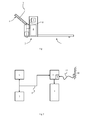
- FIG 1 schematically illustrates a so-called tiller or powered pallet truck
- figure 2 illustrates a diagram of connection of the components of the truck.
- the industrial truck comprises two load engaging lift forks 1, projecting from a truck body 2.
- a tiller arm 3, by means of which the truck is controlled, is pivotally connected to the truck body 2.
- the industrial truck is powered by a rechargeable battery 4, which is arranged in the truck body 2.
- the battery 4 can be charged by means of an onboard battery charger 5.
- the industrial truck is furnished with a truck computer 6.
- Said computer 6 can e.g. be positioned in a control handle (not shown), at the distal end of the tiller arm 3, and is provided with an input unit.
- the input unit comprises a display and/or control buttons, by means of which the user can control and monitor certain truck functions, such as speed, lifting, battery status and so on.
- the input unit of the truck computer 6 can also be used for setting operation variables, such as maximum allowable speed, maximum allowable acceleration, battery type and battery capacity.
- the operation variables are set by an external programming device, which can be connected to the truck computer 6.
- a motor control device 7 can be arranged in the industrial truck, e.g. in the truck body 2.
- the motor control device 7 distributes power to various truck components, such as a truck motor (not shown) propelling the industrial truck and a pump motor (not shown) driving the lift forks 1.
- the industrial truck also comprises a CAN network 8.
- the truck computer 6 and the battery charger 5 are connected to the CAN network 8.
- the truck computer 6 and the battery charger 5 can exchange information via the CAN network 8.
- a motor control device 7 is arranged in the industrial truck, this device 7 is also connected to the CAN network 8. All components that are connected to the CAN network are provided with CAN receiver/transmitters enabling them to communicate on the CAN network 8.
- the motor control device 7 receives control instructions from the truck computer 6 over the can network 8.
- the battery charger 5 can be furnished with an immobilising function, which, when activated, sends an immobilising signal to the truck computer 6. More in detail, the battery charger 5 can be provided with a charge detecting means 9, which detects whether the battery charger 5 is connected to a power supply 10. In figure 2 is illustrated how the battery charger 5 is connected to a power supply 10 by a power cord 11. The battery charger 5 can also be provided with a logic unit (not shown). In the charging condition, i.e. when the battery charger 5 is connected to mains 10 and the truck battery 4 is being charged, the charge detecting means 9 detects a voltage from the power cord 11 and sends a charge signal to the logic unit of the battery charger 5.
- the logic unit of the battery charger 5 When the logic unit of the battery charger 5 receives the charge signal, the logic unit initiates charging and sends an immobilising signal to the truck computer 6 over the CAN network 8. Now, the truck computer 6 ensures that the industrial truck cannot be operated, e.g. by not implementing input unit control orders, and/or by preventing power to reach the truck motor by instructing the motor control unit 7, via the CAN network 8, that the industrial truck is not to be operated. In the operational condition of the industrial truck, i.e. when the battery charger 5 is not connected to mains 10, the charge detecting means 9 is inactivated and no immobilising signal is sent to the truck computer 6.
- information can be transferred from the battery charger 5 to the truck computer 6.
- information can also be transferred in the opposite direction; from the truck computer 6 to the battery charger 5.
- information stored in the truck computer 6 regarding battery type and battery capacity can be transferred to the battery charger 5.
- a number of charging curves can be stored.
- an appropriate charging curve i.e. charging voltage to apply versus charging time, can be used by the battery charger 5 upon charging of the battery 4.
- An appropriate charging curve shortens charging time, improves battery performance and extends battery life.
- the logic unit of the battery charger 5 can be supplied with charging curves for all batteries that are suitable for the particular industrial truck.
- a battery suitable for an industrial truck is a battery of adequate capacity and outer dimensions.
- the battery charger 5 is able to execute an appropriate charging curve. If the industrial truck is furnished with a battery that requires a charging curve not stored in the logic unit of the battery charger 5, an external programming device can be connected to the truck computer 6 and/or the CAN network 8 in order to update the industrial truck. In this way, information about the new battery can be stored in the truck computer 6 and the battery charger 5.
- the truck computer 6 is updated with information regarding kind and capacity of the new battery, and the battery charger 5 is updated with the corresponding charging curve.
- the battery charger 5 applies the charging curve in question the next time the battery charger 5 is connected to mains.
- the logic unit of the battery charger 5 stores the battery information, and applies the relevant charging curve in every subsequent charging process, until new and different battery information is received via the CAN network 8.
- an external programming device is used for setting the truck operation variables, such external programming device can be connected to the truck computer 6 and/or the CAN network 8.
- the present invention can be put to use in all kinds of industrial trucks which carry an onboard battery charger.
- an industrial truck battery charger 5 in accordance with the present invention, which charger 5, in analogy with a truck computer 6, is connected to a CAN network 8, an immobilising signal can be sent to the truck computer 6, whereby truck operation is prevented during charging. Further, upon installation of a truck battery 4 in an industrial truck, an operator can efficiently provide the onboard battery charger 5 with the relevant battery information via the CAN network 8. Thus, battery installation as well as battery exchange is simplified.
- the present invention also allows a more compact design of the industrial truck, since there is no need for a manual battery switch or a connection for an external programming device on the battery charger 5.
Priority Applications (1)
| Application Number | Priority Date | Filing Date | Title |
|---|---|---|---|
| EP07123987.5A EP2072455B2 (fr) | 2007-12-21 | 2007-12-21 | Véhicule industriel |
Applications Claiming Priority (1)
| Application Number | Priority Date | Filing Date | Title |
|---|---|---|---|
| EP07123987.5A EP2072455B2 (fr) | 2007-12-21 | 2007-12-21 | Véhicule industriel |
Publications (3)
| Publication Number | Publication Date |
|---|---|
| EP2072455A1 true EP2072455A1 (fr) | 2009-06-24 |
| EP2072455B1 EP2072455B1 (fr) | 2011-10-05 |
| EP2072455B2 EP2072455B2 (fr) | 2020-08-19 |
Family
ID=39387358
Family Applications (1)
| Application Number | Title | Priority Date | Filing Date |
|---|---|---|---|
| EP07123987.5A Active EP2072455B2 (fr) | 2007-12-21 | 2007-12-21 | Véhicule industriel |
Country Status (1)
| Country | Link |
|---|---|
| EP (1) | EP2072455B2 (fr) |
Cited By (3)
| Publication number | Priority date | Publication date | Assignee | Title |
|---|---|---|---|---|
| EP2072455B2 (fr) † | 2007-12-21 | 2020-08-19 | BT Products AB | Véhicule industriel |
| EP3772151A1 (fr) | 2019-07-30 | 2021-02-03 | Delta Electronics (Thailand) Public Co., Ltd. | Circuit de protection de chargeur |
| IT202000029243A1 (it) * | 2020-12-01 | 2022-06-01 | Voltmec S R L | Sistema di ricarica di batterie al litio di veicoli industriali |
Citations (4)
| Publication number | Priority date | Publication date | Assignee | Title |
|---|---|---|---|---|
| DE19756744A1 (de) * | 1997-12-19 | 1999-07-01 | Elektron Bremen | Verfahren zum Betreiben eines Batterie-Managementsystems sowie elektronische Baugruppe hierfür |
| US20040100225A1 (en) | 2002-11-20 | 2004-05-27 | Neil Robert Miles | Cooling and control system for battery charging |
| DE10330817A1 (de) * | 2003-07-08 | 2005-01-27 | Linde Ag | Flurförderzeug mit einem elektrischen Antrieb, einer Batterie, einer elektrischen Steuerung und einer Batterieladevorrichtung |
| EP1734633A1 (fr) * | 2005-06-15 | 2006-12-20 | Jungheinrich Aktiengesellschaft | Câble capable du transmission de données et de puissance pour la connexion d'une batterie avec un chargeur |
Family Cites Families (3)
| Publication number | Priority date | Publication date | Assignee | Title |
|---|---|---|---|---|
| DE3151287A1 (de) † | 1981-12-24 | 1983-07-07 | Brown, Boveri & Cie Ag, 6800 Mannheim | Losfahrschutz fuer ein elektrofahrzeug |
| DE19922137A1 (de) † | 1999-05-12 | 2000-11-16 | Still & Saxby Sarl | Flurförderzeug mit einem Batterieblock |
| EP2072455B2 (fr) † | 2007-12-21 | 2020-08-19 | BT Products AB | Véhicule industriel |
-
2007
- 2007-12-21 EP EP07123987.5A patent/EP2072455B2/fr active Active
Patent Citations (4)
| Publication number | Priority date | Publication date | Assignee | Title |
|---|---|---|---|---|
| DE19756744A1 (de) * | 1997-12-19 | 1999-07-01 | Elektron Bremen | Verfahren zum Betreiben eines Batterie-Managementsystems sowie elektronische Baugruppe hierfür |
| US20040100225A1 (en) | 2002-11-20 | 2004-05-27 | Neil Robert Miles | Cooling and control system for battery charging |
| DE10330817A1 (de) * | 2003-07-08 | 2005-01-27 | Linde Ag | Flurförderzeug mit einem elektrischen Antrieb, einer Batterie, einer elektrischen Steuerung und einer Batterieladevorrichtung |
| EP1734633A1 (fr) * | 2005-06-15 | 2006-12-20 | Jungheinrich Aktiengesellschaft | Câble capable du transmission de données et de puissance pour la connexion d'une batterie avec un chargeur |
Cited By (4)
| Publication number | Priority date | Publication date | Assignee | Title |
|---|---|---|---|---|
| EP2072455B2 (fr) † | 2007-12-21 | 2020-08-19 | BT Products AB | Véhicule industriel |
| EP3772151A1 (fr) | 2019-07-30 | 2021-02-03 | Delta Electronics (Thailand) Public Co., Ltd. | Circuit de protection de chargeur |
| IT202000029243A1 (it) * | 2020-12-01 | 2022-06-01 | Voltmec S R L | Sistema di ricarica di batterie al litio di veicoli industriali |
| WO2022118088A1 (fr) * | 2020-12-01 | 2022-06-09 | Voltmec S.R.L. | Système de charge de batteries au lithium de véhicules industriels |
Also Published As
| Publication number | Publication date |
|---|---|
| EP2072455B2 (fr) | 2020-08-19 |
| EP2072455B1 (fr) | 2011-10-05 |
Similar Documents
| Publication | Publication Date | Title |
|---|---|---|
| US11429095B2 (en) | Pairing a remote control device to a vehicle | |
| EP2072455B1 (fr) | Véhicule industriel | |
| US8751084B2 (en) | Vehicle component recognition and adjustment for energy efficiency | |
| CN108138505B (zh) | 在遥控拆除机器人上的液压工具的自适应控制 | |
| EP2810914B1 (fr) | Chariot de manutention | |
| JP2018526236A (ja) | パワーレンチと外部操作部とを備えた工具システム | |
| US20040094379A1 (en) | Lift truck for the transport of a battery block of an industrial truck | |
| CN109910724A (zh) | 智能物流运输车 | |
| CN211223674U (zh) | 一种agv搬运小车 | |
| JP2007295728A (ja) | 過充電保護装置 | |
| US20090033288A1 (en) | Charging control device for vehicle | |
| US20080129553A1 (en) | Method for Configuring an Operating Unit of a Control and Control Device | |
| JP6793335B2 (ja) | 充電アダプタ | |
| AU2021325685B2 (en) | Remote control device | |
| JP2009028811A (ja) | ロボット制御装置 | |
| JP5740091B2 (ja) | 農作業機のバッテリ監視システム | |
| JP2003009417A (ja) | バッテリ充電装置及びそのバッテリ充電装置を装着したバッテリフォークリフト | |
| JP6072869B1 (ja) | 制御装置、車両、制御方法及び制御プログラム | |
| JP6599641B2 (ja) | 作業車 | |
| CN212421313U (zh) | 一种工具车 | |
| AU2020380962B2 (en) | Motor control for gas engine replacement device | |
| US20230365082A1 (en) | Handling machine and method for managing battery charge | |
| CN209441404U (zh) | 推车 | |
| CN108502771B (zh) | 一种装卸一体化自动导引起重机 | |
| WO2018188752A1 (fr) | Dispositif utilisable par un robot et un être humain |
Legal Events
| Date | Code | Title | Description |
|---|---|---|---|
| PUAI | Public reference made under article 153(3) epc to a published international application that has entered the european phase |
Free format text: ORIGINAL CODE: 0009012 |
|
| AK | Designated contracting states |
Kind code of ref document: A1 Designated state(s): AT BE BG CH CY CZ DE DK EE ES FI FR GB GR HU IE IS IT LI LT LU LV MC MT NL PL PT RO SE SI SK TR |
|
| AX | Request for extension of the european patent |
Extension state: AL BA HR MK RS |
|
| 17P | Request for examination filed |
Effective date: 20090609 |
|
| 17Q | First examination report despatched |
Effective date: 20090710 |
|
| AKX | Designation fees paid |
Designated state(s): DE FR GB IT SE |
|
| GRAP | Despatch of communication of intention to grant a patent |
Free format text: ORIGINAL CODE: EPIDOSNIGR1 |
|
| GRAS | Grant fee paid |
Free format text: ORIGINAL CODE: EPIDOSNIGR3 |
|
| GRAA | (expected) grant |
Free format text: ORIGINAL CODE: 0009210 |
|
| AK | Designated contracting states |
Kind code of ref document: B1 Designated state(s): DE FR GB IT SE |
|
| REG | Reference to a national code |
Ref country code: GB Ref legal event code: FG4D |
|
| REG | Reference to a national code |
Ref country code: DE Ref legal event code: R096 Ref document number: 602007017609 Country of ref document: DE Effective date: 20111201 |
|
| REG | Reference to a national code |
Ref country code: SE Ref legal event code: TRGR |
|
| PLBI | Opposition filed |
Free format text: ORIGINAL CODE: 0009260 |
|
| 26 | Opposition filed |
Opponent name: JUNGHEINRICH AKTIENGESELLSCHAFT Effective date: 20120629 |
|
| PLAX | Notice of opposition and request to file observation + time limit sent |
Free format text: ORIGINAL CODE: EPIDOSNOBS2 |
|
| REG | Reference to a national code |
Ref country code: DE Ref legal event code: R026 Ref document number: 602007017609 Country of ref document: DE Effective date: 20120629 |
|
| PLAF | Information modified related to communication of a notice of opposition and request to file observations + time limit |
Free format text: ORIGINAL CODE: EPIDOSCOBS2 |
|
| PLBB | Reply of patent proprietor to notice(s) of opposition received |
Free format text: ORIGINAL CODE: EPIDOSNOBS3 |
|
| PLAB | Opposition data, opponent's data or that of the opponent's representative modified |
Free format text: ORIGINAL CODE: 0009299OPPO |
|
| R26 | Opposition filed (corrected) |
Opponent name: JUNGHEINRICH AKTIENGESELLSCHAFT Effective date: 20120629 |
|
| REG | Reference to a national code |
Ref country code: FR Ref legal event code: PLFP Year of fee payment: 9 |
|
| PLCK | Communication despatched that opposition was rejected |
Free format text: ORIGINAL CODE: EPIDOSNREJ1 |
|
| APAH | Appeal reference modified |
Free format text: ORIGINAL CODE: EPIDOSCREFNO |
|
| APBM | Appeal reference recorded |
Free format text: ORIGINAL CODE: EPIDOSNREFNO |
|
| APBP | Date of receipt of notice of appeal recorded |
Free format text: ORIGINAL CODE: EPIDOSNNOA2O |
|
| PLAB | Opposition data, opponent's data or that of the opponent's representative modified |
Free format text: ORIGINAL CODE: 0009299OPPO |
|
| R26 | Opposition filed (corrected) |
Opponent name: JUNGHEINRICH AKTIENGESELLSCHAFT Effective date: 20120629 |
|
| APBQ | Date of receipt of statement of grounds of appeal recorded |
Free format text: ORIGINAL CODE: EPIDOSNNOA3O |
|
| APAH | Appeal reference modified |
Free format text: ORIGINAL CODE: EPIDOSCREFNO |
|
| REG | Reference to a national code |
Ref country code: FR Ref legal event code: PLFP Year of fee payment: 10 |
|
| REG | Reference to a national code |
Ref country code: FR Ref legal event code: PLFP Year of fee payment: 11 |
|
| APBU | Appeal procedure closed |
Free format text: ORIGINAL CODE: EPIDOSNNOA9O |
|
| PLAY | Examination report in opposition despatched + time limit |
Free format text: ORIGINAL CODE: EPIDOSNORE2 |
|
| PLBC | Reply to examination report in opposition received |
Free format text: ORIGINAL CODE: EPIDOSNORE3 |
|
| PUAH | Patent maintained in amended form |
Free format text: ORIGINAL CODE: 0009272 |
|
| STAA | Information on the status of an ep patent application or granted ep patent |
Free format text: STATUS: PATENT MAINTAINED AS AMENDED |
|
| 27A | Patent maintained in amended form |
Effective date: 20200819 |
|
| AK | Designated contracting states |
Kind code of ref document: B2 Designated state(s): DE FR GB IT SE |
|
| REG | Reference to a national code |
Ref country code: DE Ref legal event code: R102 Ref document number: 602007017609 Country of ref document: DE |
|
| REG | Reference to a national code |
Ref country code: SE Ref legal event code: RPEO |
|
| P01 | Opt-out of the competence of the unified patent court (upc) registered |
Effective date: 20230526 |
|
| PGFP | Annual fee paid to national office [announced via postgrant information from national office to epo] |
Ref country code: GB Payment date: 20231219 Year of fee payment: 17 |
|
| PGFP | Annual fee paid to national office [announced via postgrant information from national office to epo] |
Ref country code: SE Payment date: 20231218 Year of fee payment: 17 Ref country code: IT Payment date: 20231221 Year of fee payment: 17 Ref country code: FR Payment date: 20231226 Year of fee payment: 17 |
|
| PGFP | Annual fee paid to national office [announced via postgrant information from national office to epo] |
Ref country code: DE Payment date: 20231227 Year of fee payment: 17 |