EP2072173A1 - Verfahren zum Verbinden von Rohrboden und Rohren sowie Reibwerkzeug zur Durchführung des Verfahrens - Google Patents
Verfahren zum Verbinden von Rohrboden und Rohren sowie Reibwerkzeug zur Durchführung des Verfahrens Download PDFInfo
- Publication number
- EP2072173A1 EP2072173A1 EP08021848A EP08021848A EP2072173A1 EP 2072173 A1 EP2072173 A1 EP 2072173A1 EP 08021848 A EP08021848 A EP 08021848A EP 08021848 A EP08021848 A EP 08021848A EP 2072173 A1 EP2072173 A1 EP 2072173A1
- Authority
- EP
- European Patent Office
- Prior art keywords
- tube
- friction
- shoulder
- pin
- tool
- Prior art date
- Legal status (The legal status is an assumption and is not a legal conclusion. Google has not performed a legal analysis and makes no representation as to the accuracy of the status listed.)
- Granted
Links
Images
Classifications
-
- B—PERFORMING OPERATIONS; TRANSPORTING
- B23—MACHINE TOOLS; METAL-WORKING NOT OTHERWISE PROVIDED FOR
- B23K—SOLDERING OR UNSOLDERING; WELDING; CLADDING OR PLATING BY SOLDERING OR WELDING; CUTTING BY APPLYING HEAT LOCALLY, e.g. FLAME CUTTING; WORKING BY LASER BEAM
- B23K20/00—Non-electric welding by applying impact or other pressure, with or without the application of heat, e.g. cladding or plating
- B23K20/12—Non-electric welding by applying impact or other pressure, with or without the application of heat, e.g. cladding or plating the heat being generated by friction; Friction welding
- B23K20/122—Non-electric welding by applying impact or other pressure, with or without the application of heat, e.g. cladding or plating the heat being generated by friction; Friction welding using a non-consumable tool, e.g. friction stir welding
- B23K20/1245—Non-electric welding by applying impact or other pressure, with or without the application of heat, e.g. cladding or plating the heat being generated by friction; Friction welding using a non-consumable tool, e.g. friction stir welding characterised by the apparatus
- B23K20/1255—Tools therefor, e.g. characterised by the shape of the probe
-
- B—PERFORMING OPERATIONS; TRANSPORTING
- B23—MACHINE TOOLS; METAL-WORKING NOT OTHERWISE PROVIDED FOR
- B23K—SOLDERING OR UNSOLDERING; WELDING; CLADDING OR PLATING BY SOLDERING OR WELDING; CUTTING BY APPLYING HEAT LOCALLY, e.g. FLAME CUTTING; WORKING BY LASER BEAM
- B23K20/00—Non-electric welding by applying impact or other pressure, with or without the application of heat, e.g. cladding or plating
- B23K20/12—Non-electric welding by applying impact or other pressure, with or without the application of heat, e.g. cladding or plating the heat being generated by friction; Friction welding
- B23K20/122—Non-electric welding by applying impact or other pressure, with or without the application of heat, e.g. cladding or plating the heat being generated by friction; Friction welding using a non-consumable tool, e.g. friction stir welding
-
- F—MECHANICAL ENGINEERING; LIGHTING; HEATING; WEAPONS; BLASTING
- F16—ENGINEERING ELEMENTS AND UNITS; GENERAL MEASURES FOR PRODUCING AND MAINTAINING EFFECTIVE FUNCTIONING OF MACHINES OR INSTALLATIONS; THERMAL INSULATION IN GENERAL
- F16L—PIPES; JOINTS OR FITTINGS FOR PIPES; SUPPORTS FOR PIPES, CABLES OR PROTECTIVE TUBING; MEANS FOR THERMAL INSULATION IN GENERAL
- F16L41/00—Branching pipes; Joining pipes to walls
- F16L41/001—Branching pipes; Joining pipes to walls the wall being a pipe plate
-
- F—MECHANICAL ENGINEERING; LIGHTING; HEATING; WEAPONS; BLASTING
- F16—ENGINEERING ELEMENTS AND UNITS; GENERAL MEASURES FOR PRODUCING AND MAINTAINING EFFECTIVE FUNCTIONING OF MACHINES OR INSTALLATIONS; THERMAL INSULATION IN GENERAL
- F16L—PIPES; JOINTS OR FITTINGS FOR PIPES; SUPPORTS FOR PIPES, CABLES OR PROTECTIVE TUBING; MEANS FOR THERMAL INSULATION IN GENERAL
- F16L41/00—Branching pipes; Joining pipes to walls
- F16L41/08—Joining pipes to walls or pipes, the joined pipe axis being perpendicular to the plane of a wall or to the axis of another pipe
- F16L41/082—Non-disconnectable joints, e.g. soldered, adhesive or caulked joints
-
- F—MECHANICAL ENGINEERING; LIGHTING; HEATING; WEAPONS; BLASTING
- F28—HEAT EXCHANGE IN GENERAL
- F28F—DETAILS OF HEAT-EXCHANGE AND HEAT-TRANSFER APPARATUS, OF GENERAL APPLICATION
- F28F9/00—Casings; Header boxes; Auxiliary supports for elements; Auxiliary members within casings
- F28F9/02—Header boxes; End plates
- F28F9/04—Arrangements for sealing elements into header boxes or end plates
- F28F9/16—Arrangements for sealing elements into header boxes or end plates by permanent joints, e.g. by rolling
- F28F9/18—Arrangements for sealing elements into header boxes or end plates by permanent joints, e.g. by rolling by welding
-
- B—PERFORMING OPERATIONS; TRANSPORTING
- B23—MACHINE TOOLS; METAL-WORKING NOT OTHERWISE PROVIDED FOR
- B23K—SOLDERING OR UNSOLDERING; WELDING; CLADDING OR PLATING BY SOLDERING OR WELDING; CUTTING BY APPLYING HEAT LOCALLY, e.g. FLAME CUTTING; WORKING BY LASER BEAM
- B23K2101/00—Articles made by soldering, welding or cutting
- B23K2101/04—Tubular or hollow articles
- B23K2101/14—Heat exchangers
-
- F—MECHANICAL ENGINEERING; LIGHTING; HEATING; WEAPONS; BLASTING
- F28—HEAT EXCHANGE IN GENERAL
- F28F—DETAILS OF HEAT-EXCHANGE AND HEAT-TRANSFER APPARATUS, OF GENERAL APPLICATION
- F28F2275/00—Fastening; Joining
- F28F2275/06—Fastening; Joining by welding
- F28F2275/062—Fastening; Joining by welding by impact pressure or friction welding
Definitions
- the invention relates to a method for connecting tubesheet and tubes in a shell-and-tube heat exchanger by means of a rotating friction tool.
- Heat exchangers are devices in which the heat of a medium is discharged to another, for example by a first medium flows through a number of tubes, which are in the second medium and therefore also flows around it.
- the first medium usually flows through a plurality of tubes which are enclosed in a boiler or cylinder with inlet and outlet for the second medium.
- the second medium may be air or oil that is used elsewhere for heating.
- the tubes, through which the first medium is passed, are generally held in tube sheets at a small distance from each other, while the tube sheets themselves are supported by the jacket or cylinder of the heat exchanger.
- the tubes are fixed by rolling and beading in the tube sheets, which is sufficient at the beginning of operation for the then prevailing operating conditions usually.
- these compounds partially dissolve and then no longer meet the tightness requirements. An exchange or an expensive repair with corresponding downtime of the system are then the result.
- a method for producing a friction-welded joint in which, for example, tube sheets for heat exchangers are produced.
- the parts to be connected are firmly locked and in the area of the seam to be welded by means of a rotating and welding heat generating friction ring heated and welded.
- the friction ring used in this case serves as a filler material and can be designed differently according to the welding task to be performed in cross section. It therefore comes to the consumption of the friction ring as part of the friction tool.
- the cylindrical reaming tool has the same diameter as the tube to be welded.
- the diameter of the friction tool is smaller than the outer diameter of the tube to be welded, but larger than the inner diameter.
- the end face of the cylindrical reaming tool has profiles with which the tube is contacted.
- the object of the invention is to provide a comparison with the prior art improved method for connecting tube sheets and pipes in a shell-and-tube heat exchanger and a suitable friction tool.
- the method of the type mentioned above which is characterized in that the friction tool rotates in the open end of a tube tube surrounded by the tube bottom in the axial direction and is pressed against the end face of the tube in such a way that the Tube end and the pipe end surrounding the pipe area are plasticized and enter into a welded joint.
- the reaming tool for carrying out the method is characterized by a shaft which has a cylindrical friction pin at its free, non-clamping end, which is not consumed during friction welding, and by a subsequent to the friction pin collar with larger outer diameter than the friction pin and with a shoulder which forms the transition from the collar to the friction pin.
- a reaming tool of special form for the particular application is first of all produced and provided with a profiling which is adapted to the respective material pairing.
- the friction tool is then moved with its cylindrical frictional pin in a free end of the tube and set in rapid rotation, as is customary for the friction stir welding and the skilled person therefore known.
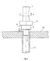
- FIG. 1 shows a section of a tube sheet 10, in which a tube 11 is inserted and held with a slight supernatant upwards.
- a friction tool is used, which at the upper end of a shaft 1 for Has clamping in the welding spindle of a friction stir welding machine, not shown.
- a cylindrical friction pin 2 is provided, which is moved in operation in the free end of the tube 11 into it. It is clear to the person skilled in the art that an adaptation of the outer diameter of the friction pin 2 and the inner diameter of the pipe 11 has to take place.
- first collar 3 and a second collar 5 are arranged, which differ in outer diameter, in such a way that the outer diameter of the first collar 3 is greater than the outer diameter of the Reibzapfens 2, and Outer diameter of the second collar 5 is larger than the outer diameter of the first collar 3.
- first collar 3 forms a first, axially directed shoulder 4 at the transition to the friction pin 2 and a second shoulder 6 at the transition to the second collar 5.
- the second shoulder 6, usually has no function in welding. It could therefore be conical or spherical shaped. With the parallel to the second shoulder 6, but at a distance extending over the annular surface, the tool is supported on the welding spindle, not shown.
- the friction tool contacts the end face 12 of the tube 11 during rotation, for example in the direction of the arrow X, thereby generating such great heat by friction that the material of the tube 11 is plasticized in the region of the end face 12.
- the first shoulder 4 contacts the region of the tubesheet 10 adjacent to the tube 11 and also plastifies it by heat generated in the rubbing operation connect the two plasticized parts 10 and 11 and form a weld.
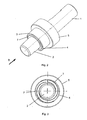
- the first shoulder 4 is provided with profilings, for example in the form of one or more spiral grooves having semicircular, triangular or rectangular cross-section.
- FIG. 3 are two spiral grooves recognizable, which are offset from each other and extend from the inside to the outside, ie from the outer diameter of the cylindrical Reibzapfens 2 to the outer diameter of the first collar.
- the friction pin 2 serves both for support and for further heating of the pipe by friction. Ideally, the frictional engagement first comes into contact with the interior of the tube 11. Therefore, the conical shape of the Reibzapfens. Thereafter, the shoulder 4 heats and plastifies the transition of pipe 4 and plate 11. The aluminum deposited on both the shoulder 4 and the friction pin 2 during the tests shows that the friction pin 2 is also involved in the friction process.
Landscapes
- Engineering & Computer Science (AREA)
- Mechanical Engineering (AREA)
- General Engineering & Computer Science (AREA)
- Physics & Mathematics (AREA)
- Thermal Sciences (AREA)
- Pressure Welding/Diffusion-Bonding (AREA)
- Branch Pipes, Bends, And The Like (AREA)
- Lining Or Joining Of Plastics Or The Like (AREA)
- Pharmaceuticals Containing Other Organic And Inorganic Compounds (AREA)
- Medicinal Preparation (AREA)
Abstract
Description
- Die Erfindung betrifft ein Verfahren zum Verbinden von Rohrboden und Rohren in einem Rohrbündel-Wärmeübertrager mit Hilfe eines rotierenden Reibwerkzeugs.
- Wärmeübertrager sind Vorrichtungen, bei denen die Wärme eines Mediums an ein anderes abgegeben wird, indem beispielsweise ein erstes Medium durch eine Anzahl von Rohren strömt, die in dem zweiten Medium liegen und daher von diesem ebenfalls umströmt werden. Um dies zu ermöglichen, strömt das erste Medium üblicherweise durch eine Vielzahl von Rohren, die in einem Kessel oder Zylinder mit Zu- und Ablauf für das zweite Medium eingeschlossen sind. Wenn das erste Medium beispielsweise Kühlwasser ist, das sich beim Kühlen einer Anlage stark erwärmt hat, kann das zweite Medium beispielsweise Luft oder Öl sein, das an anderer Stelle zum Heizen verwendet wird. Die Rohre, durch die das erste Medium geleitet wird, sind im Allgemeinen in Rohrböden in geringem Abstand zueinander gehalten, während die Rohrböden selbst vom Mantel oder Zylinder des Wärmetauschers getragen werden. Im Allgemeinen sind die Rohre durch Walzen und Umbördeln in den Rohrböden befestigt, was zu Beginn des Betriebes für die dann herrschenden Betriebsbedingungen in der Regel ausreicht. Im Zuge des weiteren Betriebes des Wärmetauschers und den dabei entstehenden Temperatur- sowie Schwingungsbelastungen lösen sich diese Verbindungen partiell auf und genügen dann nicht mehr den Dichtheitsanforderungen. Ein Austausch oder eine teure Reparatur mit entsprechenden Ausfallzeiten der Anlage sind dann die Folge.
- Man hat daher auch bereits Rohre mittels YAG-Lasers in die Rohrböden eingeschweißt, was eine aufwendige Prozesskontrolle und Prozessführung erfordert. Dennoch ist es dabei zu einem Ausgasen in der Schweißnaht gekommen, was eine Porenbildung zur Folge hatte. Ein weiterer Nachteil dieses Laserschweißverfahrens besteht darin, dass aufgrund der geringen Duktilität im lasergeschweißten Nahtbereich eine recht große Einschweißtiefe von etwa 0,8 x Rohrdicke erforderlich ist. Diese Einschweißtiefe kann mit dem YAG-Laser jedoch nicht in allen Konfigurationen erreicht werden. Da aufgrund der erforderlichen Schweißgeschwindigkeiten und der engen Radien der zugrundeliegende Geometrien nicht mit einem Zusatzwerkstoff gearbeitet werden kann, wird in absehbarer Zeit ein befriedigendes Ergebnis mit dem YAG-Laser-Schweißverfahren nicht zu erzielen sein.
- Ein weiteres bekanntes Schweißverfahren ist das MIG-Verfahren, mit dem sich ein optisch gutes Aussehen der geschweißten Nähte erzielen lässt. Aufgrund der komplexen Wärmeführung entstehen jedoch immer wieder bis knapp unter die Oberfläche der MIGnaht reichende Spannungsrisse, die die Integrität der Konstruktion beeinträchtigen. Generell sind die auf dem Aluminiumwerkstück vorhandenen hochschmelzenden Oxidhäute für die Schmelzschweißverfahren ein Hindernis, da diese erst aufgeschmolzen werden müssen, bis eine befriedigende Verbindung erzielt werden kann. Der Unterschied in der Schmelztemperatur von Aluminium mit etwa 660°C und den Oxiden mit ca. 2050°C macht ein Aufschmelzen der Oxide, die als Diffusionsbarriere ein Verschweißen sonst verhindern können, nötig. Die dafür notwendigen hohen Energien haben jedoch einen negativen Einfluss auf die niedriger schmelzenden Legierungsbestandteile der zu verschweißenden Werkstoffe. Als Folge kommt es im Nahtbereich zu Entfestigungen oder Aufhärtungen.
- Aus der
DD 205 357 - Aus der
US 2007/0138237 ist ein Verfahren zum Verschweißen der Rohrenden von Wärmetauscherrohren in Rohrböden bekannt, bei dem verschieden geformte Reibwerkzeuge auf die Rohrenden einwirken und diese durch Erwärmung verschweißen. In einer Ausführungsform hat dazu das zylindrische Reibwerkzeug den gleichen Durchmesser wie das zu verschweißende Rohr. In einer anderen Ausführungsform ist der Durchmesser des Reibwerkzeugs kleiner als der Außendurchmesser des zu verschweißenden Rohrs, jedoch größer als dessen Innendurchmesser. In wiederum anderen Ausführungsformen hat die Stirnseite des zylindrischen Reibwerkzeugs Profilierungen, mit denen das Rohr kontaktiert wird. - Aufgabe der Erfindung ist es, ein gegenüber dem Stand der Technik verbessertes Verfahren zum Verbinden von Rohrböden und Rohren in einem Rohrbündel-Wärmeübertrager und ein dazu geeignetes Reibwerkzeug zu schaffen.
- Zur Lösung dieser Aufgabe dient das Verfahren der eingangs genannten Art, welches dadurch gekennzeichnet ist, dass das Reibwerkzeug in das offene Ende eines vom Rohrboden umgebenen Rohres rotierend in dessen axialer Richtung hinein bewegt und gegen die Stirnfläche des Rohres in der Weise gedrückt wird, daß das Rohrende und der das Rohrende umgebende Bereich des Rohrbodens plastifiziert werden und miteinander eine Schweißverbindung eingehen.
- Das Reibwerkzeug zur Durchführung des Verfahrens zeichnet sich aus durch einen Schaft, der an seinem freien, nicht zum Einspannen vorgesehenen Ende einen zylindrischen Reibzapfen aufweist, der sich beim Reibschweißen nicht verbraucht, und durch einen an den Reibzapfen anschließenden Bund mit größerem Außendurchmesser als der Reibzapfen und mit einer Schulter, die den Übergang vom Bund zum Reibzapfen bildet.
- Gemäß Erfindung wird zunächst ein Reibwerkzeug von für den jeweiligen Anwendungsfall spezieller Form erzeugt und mit einer Profilierung versehen, die an die jeweilige Materialpaarung angepasst ist. Das Reibwerkzeug wird dann mit seinem zylindrischen Reibzapfen in ein freies Rohrende bewegt und in schnelle Drehung versetzt, wie sie für das Reibrührschweißen üblich und dem Fachmann daher bekannt ist. Durch weitere Hineinbewegung des Reibzapfens in das freie, nicht dargestellte Rohrende gelangt schließlich eine mit Profilierungen versehene Schulter in Kontakt mit dem freien Rohrende und erzeugt dabei eine derart hohe Reibungswärme, dass das freie Rohrende und der umgebende Bereich des Rohrbodens plastifiziert werden und miteinander eine Kreisverbindung eingehen.
- Die Erfindung wird nachfolgend anhand einer Zeichnung näher erläutert; es zeigen:
- Figur 1
- einen Ausschnitt von einem Rohrboden mit Rohr und in das Rohrende eingesetztem Reibwerkzeug;
- Figur 2
- eine perspektivische Darstellung des Reibwerkzeugs von
Figur 1 ; und - Figur 3
- eine Stirnansicht auf das Reibwerkzeug von
Figur 2 in Richtung des Pfeils A gesehen. -
Figur 1 zeigt einen Ausschnitt aus einem Rohrboden 10, in den ein Rohr 11 mit leichtem Überstand nach oben eingesetzt und gehalten ist. In das freie Ende des Rohrs 11 wird ein Reibwerkzeug eingesetzt, das am oberen Ende einen Schaft 1 zum Einspannen in die Schweißspindel einer nicht dargestellten Reibrührschweißmaschine aufweist. Am gegenüberliegenden unteren Ende ist ein zylindrischer Reibzapfen 2 vorgesehen, der im Betrieb in das freie Ende des Rohrs 11 hinein bewegt wird. Es ist dem Fachmann klar, dass dazu eine Anpassung der Außendurchmesser von Reibzapfen 2 und Innendurchmesser des Rohrs 11 zu erfolgen hat. - Zwischen dem Reibzapfen 2 und dem Schaft 1 sind ein erster Bund 3 und ein zweiter Bund 5 angeordnet, die sich im Außendurchmesser unterscheiden, und zwar in der Weise, dass der Außendurchmesser des ersten Bundes 3 größer als der Außendurchmesser des Reibzapfens 2 ist, und der Außendurchmesser des zweiten Bundes 5 größer ist als der Außendurchmesser des ersten Bundes 3. Auf diese Weise bildet der erste Bund 3 eine erste, axial gerichtete Schulter 4 am Übergang zum Reibzapfen 2 und eine zweite Schulter 6 am Übergang zum zweiten Bund 5. Die zweite Schulter 6 hat allerdings normalerweise keine Funktion beim Schweißen. Sie könnte daher auch konisch oder ballig geformt sein. Mit der parallel zur zweiten Schulter 6, jedoch im Abstand darüber verlaufenden Ringfläche stützt sich das Werkzeug an der nicht dargestellten Schweißspindel ab.
- Mit der ersten Schulter 4 kontaktiert das Reibwerkzeug bei Drehung beispielsweise in Richtung des Pfeils X die Stirnfläche 12 des Rohrs 11 und erzeugt dabei durch Reibung eine derart große Hitze, dass das Material des Rohrs 11 im Bereich der Stirnfläche 12 plastifiziert wird. Da die radiale Erstreckung der ersten Schulter 4 größer als der Außendurchmesser des Rohrs 11 ist, kontaktiert die erste Schulter 4 außerdem den zum Rohr 11 benachbart liegenden Bereich des Rohrbodens 10 und plastifiziert diesen ebenfalls durch Wärme, die bei dem Reibvorgang erzeugt wird, so dass sich die beiden plastifizierten Teile 10 und 11 verbinden und eine Schweißnaht bilden.
- Zur besseren Wärmeerzeugung im Bereich der zu bildenden Schweißnaht und damit zum schnelleren Plastifizieren von Rohrboden 10 und Rohr 11 ist die erste Schulter 4 mit Profilierungen versehen, beispielsweise in Form von ein oder mehrerer spiralförmig verlaufender Nuten, die halbkreisförmigen, dreieckigen oder rechteckigen Querschnitt haben. Bei dem Ausführungsbeispiel nach
Figur 3 sind zwei spiralförmige Nuten erkennbar, die gegeneinander versetzt sind und von innen nach außen verlaufen, also vom Außendurchmesser des zylindrischen Reibzapfens 2 zum Außendurchmesser des ersten Bundes 3. - Der Reibzapfen 2 dient sowohl zur Abstützung als auch zur weiteren Erwärmung des Rohres durch Reibung. Idealerweise kommt der Reibzapfen zuerst mit dem Inneren des Rohres 11 in Kontakt. Daher auch die konische Ausformung des Reibzapfens. Danach erwärmt und plastifiziert die Schulter 4 den Übergang von Rohr 4 und Platte 11. Das sowohl an der Schulter 4 als auch am Reibzapfen 2 während der Versuche abgelagerte Aluminium zeigt, das der Reibzapfen 2 auch am Reibvorgang beteiligt ist.
Claims (6)
- Verfahren zum Verbinden von Rohrboden (10) und Rohren (11) in einem Rohrbündel-Wärmeübertrager mit Hilfe eines rotierenden Reibwerkzeugs, dadurch gekennzeichnet, daß das Reibwerkzeug in das offene Ende eines vom Rohrboden (10) umgebenen Rohres (11) rotierend in dessen achsialer Richtung hinein bewegt und gegen die Stirnfläche des Rohres (11) in der Weise gedrückt wird, daß das Rohrende (12) und der das Rohrende umgebende Bereich des Rohrbodens (10) plastifiziert werden und miteinander eine Schweißverbindung eingehen.
- Reibwerkzeug zur Durchführung des Verfahrens nach Anspruch 1, gekennzeichnet durch einen Schaft (1), der an seinem freien, nicht zum Einspannen vorgesehenen Ende einen zylindrischen Reibzapfen (2) aufweist, der sich beim Reibschweißen nicht verbraucht, und durch einen an den Reibzapfen (2) anschließenden Bund (3) mit größerem Außendurchmesser als der Reibzapfen (2) und mit einer Schulter (4), die den Übergang vom Bund (3) zum Reibzapfen (2) bildet.
- Reibwerkzeug nach Anspruch 2, dadurch gekennzeichnet, daß die Schulter (4) des Bunds (3) mit mindestens einer Profilierung (7) versehen ist.
- Reibwerkzeug nach Anspruch 3, dadurch gekennzeichnet, daß die Profilierung (7) in der Schulter (4) vom Reibzapfen (2) aus gesehen konkav ist.
- Reibwerkzeug nach Anspruch 4, dadurch gekennzeichnet, daß die Profilierung (7) in der Schulter (4) im Querschnitt halbrund, rechteckig oder dreieckig ist.
- Verfahren zum Herstellen eines Rohrbündel-Wärmeübertragers mit Hilfe eines rotierenden Reibwerkzeugs, dadurch gekennzeichnet, daß das Reibwerkzeug in das offene Ende eines vom Rohrboden (10) umgebenen Rohres (11) rotierend in dessen achsialer Richtung hinein bewegt und gegen die Stirnfläche des Rohres (11) in der Weise gedrückt wird, daß das Rohrende (12) und der das Rohrende umgebende Bereich des Rohrbodens (10) plastifiziert werden und miteinander eine Schweißverbindung eingehen.
Priority Applications (1)
| Application Number | Priority Date | Filing Date | Title |
|---|---|---|---|
| PL08021848T PL2072173T3 (pl) | 2007-12-21 | 2008-12-16 | Sposób łączenia dna sitowego i rur |
Applications Claiming Priority (1)
| Application Number | Priority Date | Filing Date | Title |
|---|---|---|---|
| DE102007063075A DE102007063075A1 (de) | 2007-12-21 | 2007-12-21 | Verfahren zum Verbinden von Rohrboden und Rohren sowie Reibwerkzeug zur Durchführung des Verfahrens |
Publications (2)
| Publication Number | Publication Date |
|---|---|
| EP2072173A1 true EP2072173A1 (de) | 2009-06-24 |
| EP2072173B1 EP2072173B1 (de) | 2013-06-05 |
Family
ID=40427637
Family Applications (1)
| Application Number | Title | Priority Date | Filing Date |
|---|---|---|---|
| EP08021848.0A Not-in-force EP2072173B1 (de) | 2007-12-21 | 2008-12-16 | Verfahren zum Verbinden von Rohrboden und Rohren |
Country Status (13)
| Country | Link |
|---|---|
| US (1) | US7954691B2 (de) |
| EP (1) | EP2072173B1 (de) |
| JP (1) | JP5227154B2 (de) |
| CN (1) | CN101559530B (de) |
| BR (1) | BRPI0822411B1 (de) |
| CL (1) | CL2008003858A1 (de) |
| DE (1) | DE102007063075A1 (de) |
| EG (1) | EG25451A (de) |
| ES (1) | ES2427124T3 (de) |
| PE (1) | PE20091534A1 (de) |
| PL (1) | PL2072173T3 (de) |
| PT (1) | PT2072173E (de) |
| RU (1) | RU2488470C2 (de) |
Cited By (5)
| Publication number | Priority date | Publication date | Assignee | Title |
|---|---|---|---|---|
| RU2418664C1 (ru) * | 2009-09-10 | 2011-05-20 | Открытое акционерное общество "Национальный институт авиационных технологий" (ОАО НИАТ) | Способ сварки трением с перемешиванием тавровых соединений и инструмент для его осуществления |
| RU2466839C1 (ru) * | 2011-10-06 | 2012-11-20 | Российская Федерация от имени которой выступает Министерство промышленности и торговли Российской Федерации (Минпромторг России) | Способ комбинированной фрикционной сварки тавровых соединений |
| NL2007008C2 (nl) * | 2011-06-28 | 2013-01-03 | Bloksma B V | Werkwijze om leidingen in een plaat vast te zetten. |
| EP2682218A1 (de) * | 2012-07-04 | 2014-01-08 | Bloksma B.V. | Verfahren zum Befestigen von Rohren in einer Platte |
| CN121017778A (zh) * | 2025-10-28 | 2025-11-28 | 北京索德瀚智能科技有限公司 | 一种管板连接搅拌摩擦焊接装置及管板连接方法 |
Families Citing this family (29)
| Publication number | Priority date | Publication date | Assignee | Title |
|---|---|---|---|---|
| JP5210807B2 (ja) * | 2008-11-06 | 2013-06-12 | 株式会社マーレ フィルターシステムズ | 摩擦撹拌接合用ツールと摩擦撹拌接合による二部材の接合方法 |
| US8439250B2 (en) * | 2009-07-01 | 2013-05-14 | Lockheed Martin Corporation | Friction-stir weld-tool and method |
| EP2454546B1 (de) * | 2009-07-16 | 2015-09-02 | Lockheed Martin Corporation | Schraubenförmiges rohrbündel für wärmetauscher |
| AU2010273997B2 (en) | 2009-07-17 | 2014-04-17 | Lockheed Martin Corporation | Heat exchanger and method for making |
| US9777971B2 (en) | 2009-10-06 | 2017-10-03 | Lockheed Martin Corporation | Modular heat exchanger |
| US9388798B2 (en) | 2010-10-01 | 2016-07-12 | Lockheed Martin Corporation | Modular heat-exchange apparatus |
| US9670911B2 (en) | 2010-10-01 | 2017-06-06 | Lockheed Martin Corporation | Manifolding arrangement for a modular heat-exchange apparatus |
| DE102010041943A1 (de) * | 2010-10-04 | 2012-04-05 | Mahle International Gmbh | Kühler |
| JP5601210B2 (ja) * | 2011-01-14 | 2014-10-08 | スズキ株式会社 | 接合方法および接合用工具 |
| US9174301B2 (en) * | 2011-08-09 | 2015-11-03 | Lockheed Martin Corporation | Method and apparatus for friction stir welding tube ends for a heat exchanger |
| DE112014001333T5 (de) | 2013-03-12 | 2015-11-26 | Lockheed Martin Corporation | Rührreibschweissverfahren an Rohrendenfugen und ein dadurch gefertigtes Produkt |
| CN103170724B (zh) * | 2013-03-26 | 2015-07-29 | 苏州森光换热器有限公司 | 一种新的管板焊接方法 |
| DK177774B1 (en) | 2013-04-11 | 2014-06-23 | Spx Flow Technology Danmark As | HYGIENIC HEAT EXCHANGE AND METHOD FOR PREPARING A HYGIENIC HEAT EXCHANGE |
| US8857696B1 (en) * | 2014-04-01 | 2014-10-14 | King Fahd University Of Petroleum And Minerals | Method and tool for friction stir welding |
| US10359239B1 (en) | 2015-01-09 | 2019-07-23 | Lockheed Martin Corporation | Heat exchange member and heat exchangers utilizing the heat exchange member |
| ES2651500T3 (es) | 2015-03-18 | 2018-01-26 | Helmholtz-Zentrum Geesthacht Zentrum für Material- und Küstenforschung GmbH | Aparato para soldar por fricción-agitación con un resalte que comprende agujeros pasantes primero y segundo |
| ES2745406T3 (es) | 2015-04-10 | 2020-03-02 | Helmholtz Zentrum Geesthacht | Método para conectar una pieza de trabajo de superficie estructurada y una pieza de trabajo de plástico |
| CN104772561B (zh) * | 2015-04-23 | 2018-02-27 | 中国航空工业集团公司北京航空制造工程研究所 | 焊接板结构与柱体的搅拌摩擦焊接方法 |
| RU2702075C2 (ru) * | 2015-08-11 | 2019-10-03 | Линде Акциенгезельшафт | Способ соединения труб кожухотрубного теплообменника с трубной решеткой кожухотрубного теплообменника |
| CN105414740B (zh) * | 2015-12-30 | 2017-11-03 | 哈尔滨工业大学 | 一种管板结构胀焊一体化的固相扩散连接方法 |
| CN105397280B (zh) * | 2015-12-30 | 2017-08-25 | 哈尔滨工业大学 | 一种管板结构的同步胀接摩擦钎焊方法 |
| CN105414738B (zh) * | 2015-12-30 | 2018-01-30 | 哈尔滨工业大学 | 一种环形槽辅助强化管板摩擦形变扩散焊接方法 |
| CN105414739B (zh) * | 2015-12-30 | 2017-10-03 | 哈尔滨工业大学 | 一种管板与管子大结合面摩擦封焊的方法 |
| EP3405738B1 (de) * | 2016-01-19 | 2021-07-07 | Linde GmbH | Verfahren zum verbinden von rohren eines rohrbündelwärmetauschers mit einem rohrboden des rohrbündelwärmetauschers |
| KR102137907B1 (ko) * | 2019-06-24 | 2020-07-24 | 주식회사 제이에스인터거 | 축열 유닛 제조 방법 |
| US12064829B2 (en) * | 2019-09-26 | 2024-08-20 | Hitachi Astemo, Ltd. | Method for manufacturing a rod |
| CN112605523A (zh) * | 2020-12-17 | 2021-04-06 | 宁波旭升汽车技术股份有限公司 | 一种新型摩擦焊刀具 |
| CN117921164A (zh) * | 2023-12-08 | 2024-04-26 | 南京工业大学 | 基于搅拌摩擦塞焊的自动化管板接头固相连接方法 |
| CN117415441B (zh) * | 2023-12-19 | 2024-03-05 | 江苏金诺化工装备有限公司 | 一种换热器端板与传热管焊接头、焊接装置及焊接工艺 |
Citations (5)
| Publication number | Priority date | Publication date | Assignee | Title |
|---|---|---|---|---|
| CH318030A (de) | 1954-02-18 | 1956-12-15 | Sulzer Ag | Schweissverbindung eines Rohres mit einem zur Aufnahme des Rohres durchbohrten Rohrboden |
| DD205357A1 (de) | 1982-06-30 | 1983-12-28 | Udo Franz | Verfahren zur herstellung einer reibschweissverbindung |
| WO1999052669A1 (en) * | 1998-04-14 | 1999-10-21 | The Welding Institute | High performance tools for friction stir welding (fsw) |
| JP2007144479A (ja) * | 2005-11-29 | 2007-06-14 | Honda Motor Co Ltd | 摩擦撹拌接合用工具及びそれを用いた摩擦撹拌接合方法 |
| US20070138237A1 (en) | 2005-12-15 | 2007-06-21 | Hiroshi Nishikawa | Method of manufacturing heat exchanger tube and heat exchanger |
Family Cites Families (16)
| Publication number | Priority date | Publication date | Assignee | Title |
|---|---|---|---|---|
| GB1053149A (de) * | ||||
| JPS50158960A (de) * | 1974-06-14 | 1975-12-23 | ||
| SU1301612A1 (ru) * | 1984-09-06 | 1987-04-07 | Предприятие П/Я Г-4459 | Способ соединени трубчатых элементов с трубными решетками |
| JPS6156789A (ja) * | 1985-06-12 | 1986-03-22 | Oomi Kogyo Kk | 熱膨着工具によるブツシユなどを溶着する加工方法 |
| DE4225435A1 (de) * | 1992-07-31 | 1994-02-10 | Kuka Schweissanlagen & Roboter | Verfahren und Vorrichtung zum Reibschweißen zweier Werkstücke mit unterschiedlichen Querschnittskonturen |
| JPH06156789A (ja) | 1992-11-27 | 1994-06-03 | Mita Ind Co Ltd | 原稿読取装置の原稿搬送機構 |
| GB2306366A (en) * | 1995-10-20 | 1997-05-07 | Welding Inst | Friction stir welding |
| JP4732571B2 (ja) * | 2000-09-21 | 2011-07-27 | 昭和電工株式会社 | 摩擦撹拌接合用接合工具及び摩擦撹拌接合法 |
| US7097091B2 (en) * | 2001-07-25 | 2006-08-29 | Hitachi, Ltd. | Friction stir welding method and component part welded by the method |
| US6669075B2 (en) * | 2002-05-07 | 2003-12-30 | Concurrent Technologies Corporation | Tapered friction stir welding tool |
| JP4256623B2 (ja) * | 2002-05-09 | 2009-04-22 | 三菱重工業株式会社 | 摩擦攪拌接合用工具 |
| JP2006518671A (ja) * | 2003-01-30 | 2006-08-17 | スミス インターナショナル、インコーポレテッド | 高融点材料のアウト−オブ−ポジション摩擦攪拌溶接 |
| KR101067033B1 (ko) * | 2003-04-25 | 2011-09-22 | 혼다 기켄 고교 가부시키가이샤 | 튜브형 금속 본체 및 그 제조 방법 그리고 압력 용기를위한 라이너 및 그 제조 방법 |
| US20050116012A1 (en) * | 2003-11-26 | 2005-06-02 | Packer Scott M. | Method for metal and alloy joining using bulk friction stir welding |
| JP4756921B2 (ja) * | 2005-06-09 | 2011-08-24 | 住友軽金属工業株式会社 | 重合せ材料の端面接合方法 |
| JP2007301579A (ja) * | 2006-05-09 | 2007-11-22 | Osaka Industrial Promotion Organization | 摩擦攪拌加工用ツールおよびこれを用いる摩擦攪拌加工品の製造方法 |
-
2007
- 2007-12-21 DE DE102007063075A patent/DE102007063075A1/de not_active Withdrawn
-
2008
- 2008-12-16 EP EP08021848.0A patent/EP2072173B1/de not_active Not-in-force
- 2008-12-16 PT PT80218480T patent/PT2072173E/pt unknown
- 2008-12-16 ES ES08021848T patent/ES2427124T3/es active Active
- 2008-12-16 PL PL08021848T patent/PL2072173T3/pl unknown
- 2008-12-18 PE PE2008002110A patent/PE20091534A1/es not_active Application Discontinuation
- 2008-12-19 CL CL2008003858A patent/CL2008003858A1/es unknown
- 2008-12-19 RU RU2008150556/02A patent/RU2488470C2/ru not_active IP Right Cessation
- 2008-12-19 CN CN2008101074952A patent/CN101559530B/zh not_active Expired - Fee Related
- 2008-12-19 JP JP2008323076A patent/JP5227154B2/ja not_active Expired - Fee Related
- 2008-12-21 EG EG2008122053A patent/EG25451A/xx active
- 2008-12-22 BR BRPI0822411A patent/BRPI0822411B1/pt not_active IP Right Cessation
- 2008-12-22 US US12/341,144 patent/US7954691B2/en not_active Expired - Fee Related
Patent Citations (5)
| Publication number | Priority date | Publication date | Assignee | Title |
|---|---|---|---|---|
| CH318030A (de) | 1954-02-18 | 1956-12-15 | Sulzer Ag | Schweissverbindung eines Rohres mit einem zur Aufnahme des Rohres durchbohrten Rohrboden |
| DD205357A1 (de) | 1982-06-30 | 1983-12-28 | Udo Franz | Verfahren zur herstellung einer reibschweissverbindung |
| WO1999052669A1 (en) * | 1998-04-14 | 1999-10-21 | The Welding Institute | High performance tools for friction stir welding (fsw) |
| JP2007144479A (ja) * | 2005-11-29 | 2007-06-14 | Honda Motor Co Ltd | 摩擦撹拌接合用工具及びそれを用いた摩擦撹拌接合方法 |
| US20070138237A1 (en) | 2005-12-15 | 2007-06-21 | Hiroshi Nishikawa | Method of manufacturing heat exchanger tube and heat exchanger |
Cited By (5)
| Publication number | Priority date | Publication date | Assignee | Title |
|---|---|---|---|---|
| RU2418664C1 (ru) * | 2009-09-10 | 2011-05-20 | Открытое акционерное общество "Национальный институт авиационных технологий" (ОАО НИАТ) | Способ сварки трением с перемешиванием тавровых соединений и инструмент для его осуществления |
| NL2007008C2 (nl) * | 2011-06-28 | 2013-01-03 | Bloksma B V | Werkwijze om leidingen in een plaat vast te zetten. |
| RU2466839C1 (ru) * | 2011-10-06 | 2012-11-20 | Российская Федерация от имени которой выступает Министерство промышленности и торговли Российской Федерации (Минпромторг России) | Способ комбинированной фрикционной сварки тавровых соединений |
| EP2682218A1 (de) * | 2012-07-04 | 2014-01-08 | Bloksma B.V. | Verfahren zum Befestigen von Rohren in einer Platte |
| CN121017778A (zh) * | 2025-10-28 | 2025-11-28 | 北京索德瀚智能科技有限公司 | 一种管板连接搅拌摩擦焊接装置及管板连接方法 |
Also Published As
| Publication number | Publication date |
|---|---|
| PT2072173E (pt) | 2013-09-09 |
| DE102007063075A1 (de) | 2009-06-25 |
| PL2072173T3 (pl) | 2013-12-31 |
| BRPI0822411A2 (pt) | 2013-12-24 |
| RU2008150556A (ru) | 2010-06-27 |
| US7954691B2 (en) | 2011-06-07 |
| EP2072173B1 (de) | 2013-06-05 |
| US20090159643A1 (en) | 2009-06-25 |
| BRPI0822411B1 (pt) | 2016-12-13 |
| ES2427124T3 (es) | 2013-10-28 |
| JP5227154B2 (ja) | 2013-07-03 |
| CL2008003858A1 (es) | 2010-08-13 |
| CN101559530B (zh) | 2013-11-06 |
| EG25451A (en) | 2012-01-09 |
| RU2488470C2 (ru) | 2013-07-27 |
| CN101559530A (zh) | 2009-10-21 |
| JP2009148831A (ja) | 2009-07-09 |
| PE20091534A1 (es) | 2009-10-04 |
Similar Documents
| Publication | Publication Date | Title |
|---|---|---|
| EP2072173B1 (de) | Verfahren zum Verbinden von Rohrboden und Rohren | |
| EP2604963B1 (de) | Dampferzeugerheizrohrreparaturmittel und reparaturverfahren | |
| DE69412462T2 (de) | Verfahren und vorrichtung zum reparieren beschädigter rohre | |
| WO2016124168A1 (de) | VORRICHTUNG UND VERFAHREN ZUM MOBILEN RÜHRREIBSCHWEIßEN VON ZWEI ROHRARTIGEN STRUKTUREN | |
| DE2929832A1 (de) | Verfahren und vorrichtung zum verbinden von rohren durch reibungsschweissen | |
| DE3001756A1 (de) | Korrosionsfeste verbindungsanordnung | |
| EP4117849B1 (de) | Herstellungsverfahren für schweissverbindungen zwischen innenrohren und rohrträgerplatten eines rohrbündels für einen produkt-zu-produkt-rohrbündel-wärmeaustauscher mittels einer hilfsvorrichtung und hilfsvorrichtung für ein solches herstellungsverfahren | |
| EP3334994B1 (de) | Verfahren zum verbinden von rohren eines rohrbündelwärmetauschers mit einem rohrboden des rohrbündelwärmetauschers | |
| EP2790865B1 (de) | Verfahren zum fügen zweier im wesentlichen blechartiger werkstücke mittels reibquetschschweissen | |
| DE3615947C1 (en) | Welding and centring ring | |
| DE4404928A1 (de) | Heizkörper aus stoffschlüssig miteinander verbundenen Metallrohren und Verfahren für seine Fertigung | |
| EP3395493B1 (de) | Verfahren zum zusatzwerkstoff-freien laserstrahlverschweissen | |
| DE4444572C2 (de) | Verfahren zur Befestigung eines Anschlagringes am Ende eines Rohres | |
| EP0104325B1 (de) | Verfahren zum Schweissen innen plattierter zylindrischer Werkstücke | |
| DE3238776C2 (de) | Verfahren zum Aus- oder Umkleiden und untereinander Verbinden von vorgeformten Werkstücken | |
| DE19501780C2 (de) | Rohr-Flansch-Verbindung | |
| EP3691827B1 (de) | Verfahren zum verbinden flächiger bauteile sowie verbundelement | |
| EP2328717B1 (de) | Vorrichtung zur vorbereitung der stirnseiten dünnwandiger ummantelungen zum schweissen | |
| DE2504471A1 (de) | Heiz- bzw. kuehlzylinder zum heizen, kuehlen oder walzen sowie auch zum leiten verschiedenster materialien aus kunststoff, aluminium, papier oder textilien mit doppelmantel und zwangsumlauf des heizbzw. kuehlmediums | |
| DE4136349C2 (de) | Schweißvorrichtung für Kunststoffrohre | |
| DE3327529A1 (de) | Verfahren und vorrichtung zur befestigung einer metallenen futterhuelse in einem metallenen rohr durch stoffschluessige verbindung | |
| DE19635766C2 (de) | Verfahren zum Verschweißen eines Nippels mit einem rohrartigen Sammler und Sammlerbaugruppe | |
| DE102016105902B4 (de) | Verfahren zur Herstellung eines Rohres aus Metall mit unterschiedlichen Wandstärken | |
| EP0928942A2 (de) | Heizkörper, insbesondere Gliederradiator | |
| DE19702719C1 (de) | Verfahren zur Herstellung eines metallischen Rohrverbinders |
Legal Events
| Date | Code | Title | Description |
|---|---|---|---|
| PUAI | Public reference made under article 153(3) epc to a published international application that has entered the european phase |
Free format text: ORIGINAL CODE: 0009012 |
|
| AK | Designated contracting states |
Kind code of ref document: A1 Designated state(s): AT BE BG CH CY CZ DE DK EE ES FI FR GB GR HR HU IE IS IT LI LT LU LV MC MT NL NO PL PT RO SE SI SK TR |
|
| AX | Request for extension of the european patent |
Extension state: AL BA MK RS |
|
| RAP1 | Party data changed (applicant data changed or rights of an application transferred) |
Owner name: GKSS-FORSCHUNGSZENTRUM GEESTHACHT GMBH Owner name: LINDE AG |
|
| RIN1 | Information on inventor provided before grant (corrected) |
Inventor name: ROOS, ARNE Inventor name: WIMMER, GEORG Inventor name: DOS SANTOS, JORGE |
|
| 17P | Request for examination filed |
Effective date: 20091126 |
|
| 17Q | First examination report despatched |
Effective date: 20091221 |
|
| AKX | Designation fees paid |
Designated state(s): AT BE BG CH CY CZ DE DK EE ES FI FR GB GR HR HU IE IS IT LI LT LU LV MC MT NL NO PL PT RO SE SI SK TR |
|
| GRAP | Despatch of communication of intention to grant a patent |
Free format text: ORIGINAL CODE: EPIDOSNIGR1 |
|
| GRAS | Grant fee paid |
Free format text: ORIGINAL CODE: EPIDOSNIGR3 |
|
| GRAA | (expected) grant |
Free format text: ORIGINAL CODE: 0009210 |
|
| RAP1 | Party data changed (applicant data changed or rights of an application transferred) |
Owner name: HELMHOLTZ-ZENTRUM GEESTHACHT ZENTRUM FUER MATERIAL Owner name: LINDE AG |
|
| AK | Designated contracting states |
Kind code of ref document: B1 Designated state(s): AT BE BG CH CY CZ DE DK EE ES FI FR GB GR HR HU IE IS IT LI LT LU LV MC MT NL NO PL PT RO SE SI SK TR |
|
| REG | Reference to a national code |
Ref country code: GB Ref legal event code: FG4D Free format text: NOT ENGLISH |
|
| REG | Reference to a national code |
Ref country code: CH Ref legal event code: EP |
|
| REG | Reference to a national code |
Ref country code: AT Ref legal event code: REF Ref document number: 615352 Country of ref document: AT Kind code of ref document: T Effective date: 20130615 |
|
| REG | Reference to a national code |
Ref country code: IE Ref legal event code: FG4D Free format text: LANGUAGE OF EP DOCUMENT: GERMAN |
|
| REG | Reference to a national code |
Ref country code: DE Ref legal event code: R096 Ref document number: 502008010063 Country of ref document: DE Effective date: 20130801 |
|
| REG | Reference to a national code |
Ref country code: PT Ref legal event code: SC4A Free format text: AVAILABILITY OF NATIONAL TRANSLATION Effective date: 20130903 |
|
| REG | Reference to a national code |
Ref country code: SE Ref legal event code: TRGR |
|
| REG | Reference to a national code |
Ref country code: NL Ref legal event code: T3 |
|
| REG | Reference to a national code |
Ref country code: ES Ref legal event code: FG2A Ref document number: 2427124 Country of ref document: ES Kind code of ref document: T3 Effective date: 20131028 |
|
| PG25 | Lapsed in a contracting state [announced via postgrant information from national office to epo] |
Ref country code: FI Free format text: LAPSE BECAUSE OF FAILURE TO SUBMIT A TRANSLATION OF THE DESCRIPTION OR TO PAY THE FEE WITHIN THE PRESCRIBED TIME-LIMIT Effective date: 20130605 Ref country code: LT Free format text: LAPSE BECAUSE OF FAILURE TO SUBMIT A TRANSLATION OF THE DESCRIPTION OR TO PAY THE FEE WITHIN THE PRESCRIBED TIME-LIMIT Effective date: 20130605 Ref country code: SI Free format text: LAPSE BECAUSE OF FAILURE TO SUBMIT A TRANSLATION OF THE DESCRIPTION OR TO PAY THE FEE WITHIN THE PRESCRIBED TIME-LIMIT Effective date: 20130605 Ref country code: NO Free format text: LAPSE BECAUSE OF FAILURE TO SUBMIT A TRANSLATION OF THE DESCRIPTION OR TO PAY THE FEE WITHIN THE PRESCRIBED TIME-LIMIT Effective date: 20130905 Ref country code: GR Free format text: LAPSE BECAUSE OF FAILURE TO SUBMIT A TRANSLATION OF THE DESCRIPTION OR TO PAY THE FEE WITHIN THE PRESCRIBED TIME-LIMIT Effective date: 20130906 |
|
| REG | Reference to a national code |
Ref country code: LT Ref legal event code: MG4D |
|
| PG25 | Lapsed in a contracting state [announced via postgrant information from national office to epo] |
Ref country code: BG Free format text: LAPSE BECAUSE OF FAILURE TO SUBMIT A TRANSLATION OF THE DESCRIPTION OR TO PAY THE FEE WITHIN THE PRESCRIBED TIME-LIMIT Effective date: 20130905 Ref country code: HR Free format text: LAPSE BECAUSE OF FAILURE TO SUBMIT A TRANSLATION OF THE DESCRIPTION OR TO PAY THE FEE WITHIN THE PRESCRIBED TIME-LIMIT Effective date: 20130605 |
|
| PG25 | Lapsed in a contracting state [announced via postgrant information from national office to epo] |
Ref country code: LV Free format text: LAPSE BECAUSE OF FAILURE TO SUBMIT A TRANSLATION OF THE DESCRIPTION OR TO PAY THE FEE WITHIN THE PRESCRIBED TIME-LIMIT Effective date: 20130605 |
|
| REG | Reference to a national code |
Ref country code: PL Ref legal event code: T3 |
|
| PG25 | Lapsed in a contracting state [announced via postgrant information from national office to epo] |
Ref country code: SK Free format text: LAPSE BECAUSE OF FAILURE TO SUBMIT A TRANSLATION OF THE DESCRIPTION OR TO PAY THE FEE WITHIN THE PRESCRIBED TIME-LIMIT Effective date: 20130605 Ref country code: EE Free format text: LAPSE BECAUSE OF FAILURE TO SUBMIT A TRANSLATION OF THE DESCRIPTION OR TO PAY THE FEE WITHIN THE PRESCRIBED TIME-LIMIT Effective date: 20130605 Ref country code: IS Free format text: LAPSE BECAUSE OF FAILURE TO SUBMIT A TRANSLATION OF THE DESCRIPTION OR TO PAY THE FEE WITHIN THE PRESCRIBED TIME-LIMIT Effective date: 20131005 |
|
| PG25 | Lapsed in a contracting state [announced via postgrant information from national office to epo] |
Ref country code: RO Free format text: LAPSE BECAUSE OF FAILURE TO SUBMIT A TRANSLATION OF THE DESCRIPTION OR TO PAY THE FEE WITHIN THE PRESCRIBED TIME-LIMIT Effective date: 20130605 |
|
| PLBE | No opposition filed within time limit |
Free format text: ORIGINAL CODE: 0009261 |
|
| STAA | Information on the status of an ep patent application or granted ep patent |
Free format text: STATUS: NO OPPOSITION FILED WITHIN TIME LIMIT |
|
| PG25 | Lapsed in a contracting state [announced via postgrant information from national office to epo] |
Ref country code: DK Free format text: LAPSE BECAUSE OF FAILURE TO SUBMIT A TRANSLATION OF THE DESCRIPTION OR TO PAY THE FEE WITHIN THE PRESCRIBED TIME-LIMIT Effective date: 20130605 |
|
| 26N | No opposition filed |
Effective date: 20140306 |
|
| REG | Reference to a national code |
Ref country code: DE Ref legal event code: R097 Ref document number: 502008010063 Country of ref document: DE Effective date: 20140306 |
|
| REG | Reference to a national code |
Ref country code: CH Ref legal event code: PL |
|
| PG25 | Lapsed in a contracting state [announced via postgrant information from national office to epo] |
Ref country code: LU Free format text: LAPSE BECAUSE OF FAILURE TO SUBMIT A TRANSLATION OF THE DESCRIPTION OR TO PAY THE FEE WITHIN THE PRESCRIBED TIME-LIMIT Effective date: 20131216 Ref country code: MC Free format text: LAPSE BECAUSE OF FAILURE TO SUBMIT A TRANSLATION OF THE DESCRIPTION OR TO PAY THE FEE WITHIN THE PRESCRIBED TIME-LIMIT Effective date: 20130605 |
|
| REG | Reference to a national code |
Ref country code: IE Ref legal event code: MM4A |
|
| PG25 | Lapsed in a contracting state [announced via postgrant information from national office to epo] |
Ref country code: CH Free format text: LAPSE BECAUSE OF NON-PAYMENT OF DUE FEES Effective date: 20131231 Ref country code: LI Free format text: LAPSE BECAUSE OF NON-PAYMENT OF DUE FEES Effective date: 20131231 Ref country code: IE Free format text: LAPSE BECAUSE OF NON-PAYMENT OF DUE FEES Effective date: 20131216 |
|
| REG | Reference to a national code |
Ref country code: AT Ref legal event code: MM01 Ref document number: 615352 Country of ref document: AT Kind code of ref document: T Effective date: 20131216 |
|
| PG25 | Lapsed in a contracting state [announced via postgrant information from national office to epo] |
Ref country code: AT Free format text: LAPSE BECAUSE OF NON-PAYMENT OF DUE FEES Effective date: 20131216 |
|
| PG25 | Lapsed in a contracting state [announced via postgrant information from national office to epo] |
Ref country code: TR Free format text: LAPSE BECAUSE OF FAILURE TO SUBMIT A TRANSLATION OF THE DESCRIPTION OR TO PAY THE FEE WITHIN THE PRESCRIBED TIME-LIMIT Effective date: 20130605 Ref country code: CY Free format text: LAPSE BECAUSE OF FAILURE TO SUBMIT A TRANSLATION OF THE DESCRIPTION OR TO PAY THE FEE WITHIN THE PRESCRIBED TIME-LIMIT Effective date: 20130605 |
|
| PG25 | Lapsed in a contracting state [announced via postgrant information from national office to epo] |
Ref country code: HU Free format text: LAPSE BECAUSE OF FAILURE TO SUBMIT A TRANSLATION OF THE DESCRIPTION OR TO PAY THE FEE WITHIN THE PRESCRIBED TIME-LIMIT; INVALID AB INITIO Effective date: 20081216 |
|
| PG25 | Lapsed in a contracting state [announced via postgrant information from national office to epo] |
Ref country code: MT Free format text: LAPSE BECAUSE OF FAILURE TO SUBMIT A TRANSLATION OF THE DESCRIPTION OR TO PAY THE FEE WITHIN THE PRESCRIBED TIME-LIMIT Effective date: 20130605 |
|
| REG | Reference to a national code |
Ref country code: FR Ref legal event code: PLFP Year of fee payment: 8 |
|
| REG | Reference to a national code |
Ref country code: FR Ref legal event code: PLFP Year of fee payment: 9 |
|
| REG | Reference to a national code |
Ref country code: FR Ref legal event code: PLFP Year of fee payment: 10 |
|
| PGFP | Annual fee paid to national office [announced via postgrant information from national office to epo] |
Ref country code: AT Payment date: 20181019 Year of fee payment: 11 Ref country code: PT Payment date: 20181217 Year of fee payment: 11 Ref country code: SE Payment date: 20181211 Year of fee payment: 11 Ref country code: PL Payment date: 20181008 Year of fee payment: 11 Ref country code: CZ Payment date: 20181130 Year of fee payment: 11 |
|
| PGFP | Annual fee paid to national office [announced via postgrant information from national office to epo] |
Ref country code: ES Payment date: 20190102 Year of fee payment: 11 Ref country code: IT Payment date: 20181220 Year of fee payment: 11 |
|
| REG | Reference to a national code |
Ref country code: DE Ref legal event code: R081 Ref document number: 502008010063 Country of ref document: DE Owner name: LINDE GMBH, DE Free format text: FORMER OWNERS: HELMHOLTZ-ZENTRUM GEESTHACHT ZENTRUM FUER MATERIAL- UND KUESTENFORSCHUNG GMBH, 21502 GEESTHACHT, DE; LINDE AG, 80331 MUENCHEN, DE Ref country code: DE Ref legal event code: R081 Ref document number: 502008010063 Country of ref document: DE Owner name: HELMHOLTZ-ZENTRUM GEESTHACHT ZENTRUM FUER MATE, DE Free format text: FORMER OWNERS: HELMHOLTZ-ZENTRUM GEESTHACHT ZENTRUM FUER MATERIAL- UND KUESTENFORSCHUNG GMBH, 21502 GEESTHACHT, DE; LINDE AG, 80331 MUENCHEN, DE |
|
| REG | Reference to a national code |
Ref country code: SE Ref legal event code: EUG |
|
| PG25 | Lapsed in a contracting state [announced via postgrant information from national office to epo] |
Ref country code: CZ Free format text: LAPSE BECAUSE OF NON-PAYMENT OF DUE FEES Effective date: 20191216 |
|
| REG | Reference to a national code |
Ref country code: NL Ref legal event code: MM Effective date: 20200101 |
|
| REG | Reference to a national code |
Ref country code: BE Ref legal event code: MM Effective date: 20191231 |
|
| PG25 | Lapsed in a contracting state [announced via postgrant information from national office to epo] |
Ref country code: NL Free format text: LAPSE BECAUSE OF NON-PAYMENT OF DUE FEES Effective date: 20200101 |
|
| PG25 | Lapsed in a contracting state [announced via postgrant information from national office to epo] |
Ref country code: PT Free format text: LAPSE BECAUSE OF NON-PAYMENT OF DUE FEES Effective date: 20200717 Ref country code: IT Free format text: LAPSE BECAUSE OF NON-PAYMENT OF DUE FEES Effective date: 20191216 Ref country code: SE Free format text: LAPSE BECAUSE OF NON-PAYMENT OF DUE FEES Effective date: 20191217 |
|
| PG25 | Lapsed in a contracting state [announced via postgrant information from national office to epo] |
Ref country code: BE Free format text: LAPSE BECAUSE OF NON-PAYMENT OF DUE FEES Effective date: 20191231 |
|
| REG | Reference to a national code |
Ref country code: ES Ref legal event code: FD2A Effective date: 20210602 |
|
| PG25 | Lapsed in a contracting state [announced via postgrant information from national office to epo] |
Ref country code: ES Free format text: LAPSE BECAUSE OF NON-PAYMENT OF DUE FEES Effective date: 20191217 |
|
| PG25 | Lapsed in a contracting state [announced via postgrant information from national office to epo] |
Ref country code: PL Free format text: LAPSE BECAUSE OF NON-PAYMENT OF DUE FEES Effective date: 20191216 |
|
| PGFP | Annual fee paid to national office [announced via postgrant information from national office to epo] |
Ref country code: FR Payment date: 20211220 Year of fee payment: 14 Ref country code: GB Payment date: 20211222 Year of fee payment: 14 |
|
| PGFP | Annual fee paid to national office [announced via postgrant information from national office to epo] |
Ref country code: DE Payment date: 20211220 Year of fee payment: 14 |
|
| REG | Reference to a national code |
Ref country code: DE Ref legal event code: R119 Ref document number: 502008010063 Country of ref document: DE |
|
| GBPC | Gb: european patent ceased through non-payment of renewal fee |
Effective date: 20221216 |
|
| PG25 | Lapsed in a contracting state [announced via postgrant information from national office to epo] |
Ref country code: GB Free format text: LAPSE BECAUSE OF NON-PAYMENT OF DUE FEES Effective date: 20221216 Ref country code: DE Free format text: LAPSE BECAUSE OF NON-PAYMENT OF DUE FEES Effective date: 20230701 |
|
| PG25 | Lapsed in a contracting state [announced via postgrant information from national office to epo] |
Ref country code: FR Free format text: LAPSE BECAUSE OF NON-PAYMENT OF DUE FEES Effective date: 20221231 |