EP2072077A1 - Vorrichtung zur Injektion eines Implantats - Google Patents
Vorrichtung zur Injektion eines Implantats Download PDFInfo
- Publication number
- EP2072077A1 EP2072077A1 EP08172142A EP08172142A EP2072077A1 EP 2072077 A1 EP2072077 A1 EP 2072077A1 EP 08172142 A EP08172142 A EP 08172142A EP 08172142 A EP08172142 A EP 08172142A EP 2072077 A1 EP2072077 A1 EP 2072077A1
- Authority
- EP
- European Patent Office
- Prior art keywords
- implant
- needle
- retaining
- injection
- piston
- Prior art date
- Legal status (The legal status is an assumption and is not a legal conclusion. Google has not performed a legal analysis and makes no representation as to the accuracy of the status listed.)
- Granted
Links
- 239000007943 implant Substances 0.000 title claims abstract description 201
- 238000002347 injection Methods 0.000 title claims abstract description 118
- 239000007924 injection Substances 0.000 title claims abstract description 118
- 230000004224 protection Effects 0.000 claims abstract description 29
- 238000011144 upstream manufacturing Methods 0.000 claims abstract description 17
- 230000033001 locomotion Effects 0.000 claims abstract description 16
- 230000001681 protective effect Effects 0.000 claims abstract description 9
- 230000009849 deactivation Effects 0.000 claims description 14
- 230000001960 triggered effect Effects 0.000 claims description 8
- 230000009975 flexible effect Effects 0.000 claims description 7
- 230000000881 depressing effect Effects 0.000 claims description 4
- 230000014759 maintenance of location Effects 0.000 claims description 3
- 238000012795 verification Methods 0.000 claims description 3
- 230000006835 compression Effects 0.000 abstract description 3
- 238000007906 compression Methods 0.000 abstract description 3
- 210000003811 finger Anatomy 0.000 description 18
- 230000000717 retained effect Effects 0.000 description 11
- 230000000694 effects Effects 0.000 description 10
- 230000000994 depressogenic effect Effects 0.000 description 9
- 239000003826 tablet Substances 0.000 description 8
- 239000007787 solid Substances 0.000 description 6
- 238000006073 displacement reaction Methods 0.000 description 5
- 239000003814 drug Substances 0.000 description 5
- 239000007788 liquid Substances 0.000 description 5
- 229940079593 drug Drugs 0.000 description 4
- 238000012546 transfer Methods 0.000 description 4
- 230000009471 action Effects 0.000 description 3
- 230000006378 damage Effects 0.000 description 3
- 230000000254 damaging effect Effects 0.000 description 3
- 230000001354 painful effect Effects 0.000 description 3
- 230000036961 partial effect Effects 0.000 description 3
- 229920001606 poly(lactic acid-co-glycolic acid) Polymers 0.000 description 3
- 238000003825 pressing Methods 0.000 description 3
- 230000003578 releasing effect Effects 0.000 description 3
- 230000002441 reversible effect Effects 0.000 description 3
- AEMRFAOFKBGASW-UHFFFAOYSA-N Glycolic acid Chemical class OCC(O)=O AEMRFAOFKBGASW-UHFFFAOYSA-N 0.000 description 2
- 241000287107 Passer Species 0.000 description 2
- 240000008042 Zea mays Species 0.000 description 2
- 230000008901 benefit Effects 0.000 description 2
- 230000005484 gravity Effects 0.000 description 2
- JVTAAEKCZFNVCJ-UHFFFAOYSA-N lactic acid Chemical class CC(O)C(O)=O JVTAAEKCZFNVCJ-UHFFFAOYSA-N 0.000 description 2
- 238000012423 maintenance Methods 0.000 description 2
- 238000000034 method Methods 0.000 description 2
- 230000004044 response Effects 0.000 description 2
- 210000003813 thumb Anatomy 0.000 description 2
- 101100536354 Drosophila melanogaster tant gene Proteins 0.000 description 1
- 241000282414 Homo sapiens Species 0.000 description 1
- 241000897276 Termes Species 0.000 description 1
- 239000012876 carrier material Substances 0.000 description 1
- 230000008859 change Effects 0.000 description 1
- 150000001875 compounds Chemical class 0.000 description 1
- 230000000593 degrading effect Effects 0.000 description 1
- 230000001419 dependent effect Effects 0.000 description 1
- 230000005489 elastic deformation Effects 0.000 description 1
- 229940082150 encore Drugs 0.000 description 1
- 238000001125 extrusion Methods 0.000 description 1
- 238000005562 fading Methods 0.000 description 1
- 210000004247 hand Anatomy 0.000 description 1
- 230000001965 increasing effect Effects 0.000 description 1
- 238000003780 insertion Methods 0.000 description 1
- 230000037431 insertion Effects 0.000 description 1
- 238000010255 intramuscular injection Methods 0.000 description 1
- 239000007927 intramuscular injection Substances 0.000 description 1
- 239000000463 material Substances 0.000 description 1
- 230000007246 mechanism Effects 0.000 description 1
- 230000037368 penetrate the skin Effects 0.000 description 1
- 230000008569 process Effects 0.000 description 1
- 230000000284 resting effect Effects 0.000 description 1
- 230000000452 restraining effect Effects 0.000 description 1
- 238000010254 subcutaneous injection Methods 0.000 description 1
- 239000007929 subcutaneous injection Substances 0.000 description 1
- 238000013519 translation Methods 0.000 description 1
- 230000000007 visual effect Effects 0.000 description 1
- 239000011800 void material Substances 0.000 description 1
Images
Classifications
-
- A—HUMAN NECESSITIES
- A61—MEDICAL OR VETERINARY SCIENCE; HYGIENE
- A61M—DEVICES FOR INTRODUCING MEDIA INTO, OR ONTO, THE BODY; DEVICES FOR TRANSDUCING BODY MEDIA OR FOR TAKING MEDIA FROM THE BODY; DEVICES FOR PRODUCING OR ENDING SLEEP OR STUPOR
- A61M37/00—Other apparatus for introducing media into the body; Percutany, i.e. introducing medicines into the body by diffusion through the skin
- A61M37/0069—Devices for implanting pellets, e.g. markers or solid medicaments
Definitions
- the present invention relates to the technical field of injecting one or more implants into the body of a subject. More specifically, but not exclusively, the invention relates to intramuscular or subcutaneous injection of one (or more) pharmaceutical compound in the solid or semi-solid state, which is designated "implant" in the after.
- the subject may be a mammal, including a human being. It will be called “subject” or “patient” in the following.
- This implant is injected periodically, for example every month, into the body of the subject, about 10 mm (millimeters) from the surface of the skin of the subject, this implant then dissolving in the body of the subject, during the month.
- the implant is an electronic chip used for the identification of a living being.
- a disadvantage of such a device lies in the fact that the deformation of the flexible fingers causes stressing of the tablets. Indeed, the tablets undergo the compression of both the piston on which the user presses and flexible fingers that exert some resistance before fading.
- it can be problematic to put them under stress. Indeed, some implants are particularly fragile or easily deformable, because they include materials intended to dissolve in the body of the subject. Thus, the pressure exerted on these implants can damage them.
- the pressure exerted on it increases its diameter, so that the implant remains blocked inside the device.
- the present invention aims in particular to provide a device ensuring that the implants injected into the body of the subject are intact.
- the present invention further provides a device for retro-injecting an implant.
- the retro-injection consists of injecting the implant during the removal of the needle.
- the inventors propose to provide a device arranged such that the user of the device can manually control the removal of the needle from the body of a patient. Indeed, it seeks to avoid automatic withdrawal of the needle, under the single action of a spring, because this automatic withdrawal can be painful for the patient for two reasons in particular: the user who injects the implant may not be used to using a retro-injection device, and it also happens that the needle of the retro-injection device is particularly long.
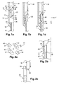
- an injection device 10 comprises a body 12 for receiving an implant, this body 12 comprising a distal end 14, to which is fixed, permanently in this example, an injection needle 16, intended to be depressed in the body of a subject.
- the injection device further comprises a piston 18, the piston 18 comprising a rod, whose proximal end is provided with a pusher (not shown), and the distal end is provided with a thrust surface 20.
- the piston 18 may be made in several segments, as in the case of the third and fourth embodiments.
- the device 10 is intended to receive an implant 22 in the solid or semi-solid state.
- the implant 22 is a single block, but it could be composed of several dissociated tablets superimposed on each other.
- the needle 16 is hollow, it has a diameter of 2 mm, and a length of about 40 mm. It is intended to deposit the implant 22 at a depth of about 10 mm from the surface of the subject's skin.
- the implant 22 is particularly fragile or deformable, it is intended to dissolve in the body of the subject, for example in a period of one month from the injection. It is made by an extrusion or injection process, and comprises a carrier material, made of PLA or PLGA, mixed with a drug.
- the receiving body 12 is arranged just upstream of the injection needle 16. Furthermore, the device 10 comprises viewing means 17, for checking the presence of an implant 22 in the device. These means 17 are, for example, a lumen formed in the receiving body 12, arranged so that the implant 22 can be seen when it is received in the device, in a manner similar to that shown in FIG. figure 1a .
- the upstream direction is designated with reference to the direction of injection of the implant 22.
- the body 12 is arranged upstream of the needle 16, that is to say that it is arranged between the needle 16 and the proximal end (end opposite the needle) of the device 10.
- the device 10 further comprises means 26 for retaining the implant 22 in the receiving body 12, these means being able to assume an activated position, visible on the figure 1a , and a disabled position, visible on the figure 1c .
- the retaining means are a retaining element 26, generally tubular openwork.
- the element 26 is slidably mounted inside the receiving body 12.
- This element 26 comprises a tubular housing 28 intended to receive the implant 22.
- This housing 28 is configured so as not to exert substantially stress on the implant 22 when received in the element 26, that the retaining means are in the activated position or in the deactivated position.
- the retaining means comprise a proximal end 30 and a distal end 32.
- the distal end 32 carries a stop 34 distally retaining the implant, which can take an activated position of restraint, visible on the figure 1a , and a disabled hold position, visible on the figure 1c .
- the retaining stop 34 extends in the transverse direction Y of the device 10, this direction Y being perpendicular to the longitudinal direction X of the device 10.
- the retaining stopper 34 when it is in the activated position, is configured to act in response to the weight of the implant 22 when the device 10 is in the vertical position, the needle 16 downward, as shown in the figures, to prevent the implant 22 passing through the needle 16, under the effect of gravity, when the device is in the position illustrated on the figure 1a .
- this stop 34 is arranged below the implant 22, more precisely between the implant 22 and the proximal end 36 of the needle.
- the stop 34 in its activated position, therefore holds the implant 22 in the housing 28, upstream of the needle 16.
- the distal end 32 of the retaining means 26 is movable between an activated position, visible on the figure 1a , and a disabled position visible on the figure 1c , for example by means of at least one elastic tab carried by this end 32, this tab carrying the stop 34.
- the device 10 further comprises means for deactivating the distal retaining means 34.
- deactivating means comprise a ramp 38, formed on the distal end of the retaining element 26, secured to the stop 34, this ramp being intended to cooperate with a ramp 40 formed on the inner distal end of the receiving body 12, so that when the retainer 26 is in the activated position illustrated on the figure 1a , the displacement of this element 26 in the direction X generates a cooperation of the ramps 38, 40, so that the distal retaining stop 34 takes its deactivated position, visible on the figure 1 vs.
- the proximal end 30 of the retaining element also has a proximal retaining stop 42 for retaining the implant in the housing 28 when the device 10 is in a vertical position, the needle 16 being upward (position opposite to that schematized on the figure 1a ).
- the abutment 42 extends in the transverse direction Y of the device 10.
- This abutment 42 is carried by one or more elastic tabs carried by the proximal end 30 of the retaining element 26.
- the end 30 is also intended to to be traversed by the piston 18, and comprises a surface 44, forming a ramp and intended to cooperate with a frustoconical surface 46 of the distal end of the piston 18.
- the ramp 44 is intended first to form a stop for the distal end of the piston 18, as can be seen on the figure 1b , then to deviate radially by elastic deformation, when the element 26 is at the end of travel in the receiving body 12.
- the means 44, 46 are means for deactivating the retaining stop 42.
- the retaining means 26 are configured so as not to exert stress on the implant 22.
- these means 26 exert a pressure on the implant 22, this pressure does not exceed a certain dependent force fragility or deformability of the implant. According to the implant, this force does not exceed 1 Newton, or does not exceed 20 Newton, so that the pressure is not likely to damage or to swell the implant 22.
- the element 26 is retained in the position illustrated on the figure 1a thanks to means for holding the element 26 in the receiving body 12.
- This maintenance results for example from a slight friction between the element 26 and the receiving body 12, this friction being erasable when the user of the device 10 exerts a force of push on the piston 18, as can be seen on the figure 1b , so that the element 26 is able to move in the direction X when pressing the piston 18.
- the retaining means 26 are in the activated position, the retaining abutments 34, 42 holding the implant inside the housing 28.
- the implant 22 is retained upstream of the needle. injection 16, and one can check its presence through means 17 for checking the presence of the implant.
- the element 26 is frictionally retained in the body 12 according to the position illustrated in FIG. figure 1a , thanks to the holding means described above.
- the needle 16 is positioned to be at least partially embedded in the body of the subject.
- the needle 16 of the figure 1a is fully sunk into the body of the subject, i.e., at a depth, relative to the skin surface of the subject, corresponding to the depth at which the implant 22 is to be placed, by
- the distal end of the needle 16 is 10 mm from the skin of the subject. Note that, even if the needle 16 is fully sunk into the skin, it is nevertheless possible to check the presence of the implant 22 by the means 17.
- the implant 22 is then released, so as to introduce it firstly into the needle 16 (as can be seen in FIG. figure 1c ) then in the skin of the subject.
- the user of the implant device 10 presses on the pusher of the piston 18, which has the effect of moving it in the longitudinal direction X, downwards.
- the abutment surface 46 of the piston rests on the abutment surface 44, which has the effect of displacing the retaining element 26 in the X direction, as can be seen in FIG. figure 1 b.
- the friction force exerted by the holding means of the element 26 in the body 12 is less than the thrust exerted by the piston 18 on the abutment surface 44, so that the element 26 moves in the X direction when the piston 18 is pressed.
- the ramps 38 and 40 cooperate, which has the effect of radially spacing the elastic tabs of the distal end 32, and in particular the retaining stop 34.
- This retaining stop 34 being spaced from the central axis of the injection device 10, it is in the deactivated position, so that it no longer ensures the retention of the implant 22 in the housing 28.
- the additional thrust of the piston 18 by the user generates the deformation of the proximal end 30 of the retaining element 26.
- the surface 46 of the piston cooperates with the ramp 44 which is deformed, so as to let the piston 18 pass through the retaining element 26.
- the piston 18 can thus push the implant 22 so as to introduce it into the needle 16, as can be seen on the figure 1c .
- the implant 22 is in the needle, and can then be injected into the body of the subject.
- the various deactivation means on the one hand the ramps 38, 40, on the other hand the ramps 44, 46, are triggered automatically, only once the needle 16 is depressed in the body of the subject.
- These deactivation means are triggered by the piston 18, more precisely by the passage of the piston from an initial position, visible on the figure 1a , at a final position, visible on the figure 1c .
- the deactivation means 38, 40; 44, 46 act directly on the retaining means 26, more precisely by cooperation between the receiving body 12 and the retaining element 26 on the one hand, and between the piston 18 and the retaining element 26 on the other. go. Consequently, these deactivation means do not act directly on the implant 22, so that there is no stress on the implant to deactivate the retaining means.
- the element 26 is held in the receiving body 12 by friction between the element 26 and the body 12.
- the retaining means 26 of this embodiment comprise, at their proximal end 30, four elastic tabs.
- Two of the diametrically opposed elastic tabs 47 are provided with lugs 48 on their outer surface, these lugs being intended to cooperate with a slot 49 made in the receiving body 12, as can be seen in FIG. figure 2b .
- These means 48, 49 constitute a high positioning stop of the element 26, intended to ensure its maintenance in an initial position similar to that of the figure 1a , by a light snap.
- the retaining element is a generally tubular element 26, the distal end 32 and proximal 30 of which comprise elastic tabs.
- the retaining means can take a multiplicity of other forms.
- this retaining element 26 could have a generally frustoconical shape, the diameter of its distal end 32 being greater than the diameter of its proximal end 30, so as to guarantee more safely the respective cooperation of the elements 38, 40 , 44, 46.
- this element 26 is not necessarily a separate part from the other parts of the implant device, the retaining means can be provided on one or more parts of the injection device 10 having another function. that the retention of the implant 22.
- injection device described in the foregoing may be a retro-injection device, as will be described later.
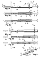
- the device 60 comprises an injection needle 62, covered, before the beginning of the use of the device 60, by a protective cap 64.
- the device 60 further comprises an intermediate body 66 and protection means 68, hereinafter referred to as "protective sheath 68", intended to cover the needle after use of the device, as can be seen in the figures 3d to 3f .
- the intermediate body 66 is external, and the sheath 68 is arranged inside the intermediate body 66, coaxially with respect to the longitudinal axis X of the device.
- the sleeve 68 has two parts, namely a distal portion 67, providing the protection function of the needle when the device is in the safety position, and a proximal portion 69, attached to the distal portion 67 , in particular ensuring a function of maintaining the sleeve in the injection position, and also keeping the sleeve in the safety position.
- the intermediate body 66 carries gripping means 70 of the device.
- the gripping means 70 comprise a stop 72 of the user's finger support, in particular of the index and major of the user.
- the gripping means 70 comprise a flange of revolution formed projecting from the intermediate body 66, near its proximal end 74.
- the device 60 further comprises a piston 76.
- the piston 76 comprises a pusher 78, intended to serve as a support for the thumb of the user, a proximal portion 80, and a distal portion 82, separable from the proximal portion 80.
- the piston 76 further comprises means 84 of FIG. release of return means, such as this is described hereinafter, these means 84 comprising a funnel shape formed between the proximal portion 80 and the pusher 78, intended to form a ramp when the piston is moved in the direction illustrated by the arrow 86.
- the device 60 further comprises return means 88, arranged between the intermediate body 66 and the sheath 68, being compressed when the device 60 is in the injection position, and can take an extended position, or rest, when the device is in a safe position, as can be seen on the figures 3d to 3f .
- the means 88 are a compression spring.
- the means 88 are maintained in the compressed state, in the injection position, by means of a distal stop 90, formed on the sheath 68, and a proximal stop 92, formed on the intermediate body 66.
- the distal stop 90 of the sheath is movable in translation to a safety position.
- the stop 90 also ensures a locking function of the sleeve 68 in the safety position, cooperating by snapping with means such as elastic tabs 94 with radial clearance, carried by the intermediate body 66.
- the sheath 68 is held in the injection position by means of retractable lugs 96 formed on its proximal portion 69, more precisely in the vicinity of the proximal end of this proximal portion 69.
- the proximal portion 69 also comprises means 98 for releasing return means 88, intended to cooperate with the means 84 of the piston 76.
- the sheath 68 and the intermediate body 66 together form, at their distal end, a receiving body of one (or more) implant 100, arranged upstream of the needle 62, intended to be injected into the body of a patient.
- the device 60 further comprises means 102 for retaining the implant 100 in the receiving body.
- the retaining means 102 ensure their retaining function by means of flexible fingers exerting a slight pressure on the implant 102. Nevertheless, these retaining means 102 may be replaced by retaining means such as presented above, for example by the retaining means 26, deactivatable by deactivation means so as not substantially to exert stress on the implant 100.
- the intermediate body 66 further comprises verification means 104, composed in this example of a window formed in the body 66, to show that the implant 100 is effectively retained by the retaining means 102.
- the implant 100 is present in the device, its presence being verified by the means 104.
- the injection begins with a withdrawal of the protective cap 64, so as to reveal the needle 62, so that the user of the device makes it penetrate into the body of the patient in which it is desired to inject the implant 100.
- the user grasps the device 60 between his index finger and his major finger, these two fingers resting on the gripping means 72, the thumb of the user being called to push on the pusher 78 in the direction of the arrow 86.
- the needle is completely discovered before being introduced into the patient's body, so that the user can see precisely what he is doing, and manually control the depression of the needle, as for a liquid injection device.
- the user pushes on the piston 76, by pressing the pusher 78.
- the displacement of the pusher 78 causes the movement of the proximal portion 80 and the distal portion 82 of the piston, which itself causes the displacement of the implant 100 in the needle 62.
- the piston 76 arrives at a position in which the means 84 are able to cooperate with the means 98. More specifically, the ramp 84 of the piston 76 causes the radial spacing of the ramp 98 of the sheath 68, this spacing causing the retraction pins 96, thus the release of the return means 88.
- This displacement has the effect of moving the sheath 68 towards the direction 86, which causes, on the one hand, the displacement of the portion 82 of the piston, previously secured to the sheath 68 (by friction or snapping), inside the needle, in order to hold the implants in place, and secondly the establishment of the position of safety by the sheath 68, visible on the figures 3d to 3f so that the sleeve 68 can cover the needle 62 as it is withdrawn from the patient's body. Once the needle is completely withdrawn, the sleeve 68 covers it completely, and the stops 90 cooperate with the means 94 of the body 66, so as to lock the device in the safety position. Because the portion 82 of the piston automatically pushes on the implant, under the effect of the release of the sheath, to maintain it in the body of the user, it is called automatic back-injection.
- the retro-injection can be, alternatively, manual.
- the piston 76 is in one piece, not securable to the sheath 68, and the injection of the implant takes place before the retraction of the lugs 96.
- the user can perform a slight backward movement of the device 60, which generates a start of withdrawal of the needle, and thus leaves room in the patient's body for introduce the implant 100 without constraint.
- the user can press again on the pusher 78, which allows the piston 76 (not integral with the sleeve) to push the implant 100 in the body of the patient. Then, the additional depression of the pusher 78 causes the retraction of the lugs 96, thus the automatic release of the protection means 68.
- the distance between the gripping means 70 and the skin of the patient 106 has been increased by the value D 1 , when the device is in the injection position at the value D 2 , when the device is in the safety position.
- the device 60 allows the retro-injection of the implant 100, that is to say that the implant 100 is injected, more precisely remains in position in the body of the patient, at the time of removal of the needle. 62 outside the body of the patient.
- automatic protection of the needle is provided by the sheath 68, at the time of its withdrawal, the needle not being left uncovered, while offering the possibility to the user to manually control the withdrawal.
- the user's fingers By removing the needle 62 from the skin 106 of the patient, the user's fingers move, moving backwards. If the user does not control his fingers, they are driven by the movement of the return means 88 which trigger the exit of the sleeve 68 from the intermediate body 66. In this case, the removal of the needle is done automatically, without control user's Guide. Nevertheless, the user can manually control the withdrawal of the needle, by controlling the movement of the means 88 via the means 70. Indeed, the user can for example slow down or stop the movement of the means 88, by exerting a force on the gripping means 70 against the force exerted by the return means 88.
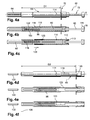
- the feedback device 60 illustrated on the Figures 4a to 4f has a different structure of the device Figures 3a to 3f , but a similar operation.
- the sleeve 68 is disposed outside, and the intermediate body 66 is arranged, coaxially with respect to the axis X, inside the sleeve 68.
- the sleeve 68 carries, at its proximal end, retractable means 110, composed in the example of two elastic tabs 110, each provided with retractable lugs 112, intended to cooperate with the intermediate body 66. retractable tabs 110 further include ramps 113, intended to cooperate with the piston 72.
- the sleeve 68 also comprises means 114 in the example for cooperating with the intermediate body 66.
- the sheath 68 comprises a stop 115 intended to serve as a support for the return means 88.
- the intermediate body 66 comprises a body 116 for receiving the implant 100, the implant being retained by the retaining means 102.
- the intermediate body 66 comprises a stop 118 intended to serve as a support for the proximal end of the return means 88.
- the intermediate body 66 is composed of two parts, namely a proximal portion 120 , carrying the gripping means 70, attached to a distal portion 122, comprising the receiving body of the implant 100.
- the intermediate body 66 is provided with means 123 for locking the sheath 68 in the safety position, in this case pins 123 intended to cooperate with the slots 114.
- the pusher 78 of the piston 72 is provided with means 124 for releasing the locking means 112, thanks to a cap shape of the pusher 78.
- the user begins by removing the protective cap 64 and then introducing the needle 62 into the body of the patient. Then, the user presses the pusher 78, which has the effect of moving the rods 80 and 82 of the piston 72, so the implant 100 which is introduced into the distal end of the needle 62.
- the release means 124 cooperate with the elastic ramp 113, so as to radially move the elastic tabs 110 and thus retract the lugs 112. Once the lugs 112 retracted, the return means 88 are released and may extend in the direction indicated by the arrow 126.
- This release of return means 88 has the effect of moving the intermediate body 66 in the direction of the arrow 126, and thus to protect the needle 62 by the sheath 68 , as can be seen from the Figures 4d to 4f . Then, the device is maintained in the safety position, by means of cooperation means 114 and 123.
- the user can manually control the removal of the needle from the skin of the patient 106.
- the device 60 includes means 107 for indicating the distal grip of the device, the distal gripping being intended to facilitate the insertion of the needle into the needle. patient's body.
- These means 107 are arranged on the body 66, at near its distal end. They can be composed of a visual indication, a protuberance (which is the case on the figure 5 ), or a grainy surface. They are intended to indicate to the user a distal zone that the user can use to implement the injection.
- indication means 107 may be provided on all other embodiments. In the case of the embodiment of figures 4 the means 107 could be provided on the sheath 68.
- the device 60 Before starting to prick the patient, the device 60 is in the configuration of the figure 5 .
- the user grasps the device 60 by its distal portion, preferably holding the indication zone 107 between the fingers of his right hand if he is right-handed. Indeed, it may be more convenient for the user to introduce the needle by holding the device 60 at this area 107, because the device 60 may be relatively long (it may be for example a length of 200 mm between the end of the needle 62 and the pusher 78). Specifically, the user holds with his right hand the proximal end 108 of the indication zone 107.
- the user can pinch the patient's body, to create a hard surface for introduce the needle. Once the needle is fully depressed in the patient's body, the user can stop pinching the patient's body, and seize, with his left hand released, the distal end 109 of the zone 107, so as to release his right hand which releases the end 108 and can seize the gripping means 70 to activate the piston 76 and proceed to the steps of injection and withdrawal of the needle.
- the piston 76 is rather in one part, and the retro-injection is preferably manual.
- the embodiments of the retro-injection device 60 may take other forms than those described. In particular, the embodiments may be combined with any one of the other embodiments.
- the devices of the third fourth and fifth embodiments are implant retro-injection devices, preferably automatic retro-injection, but can also implement manual retro-injection, as has been described.
- the invention proposes to manually control the movement of the means. protection 68, from the gripping means 70.
- the user himself proceeds to the injection of the implant, by retracting the needle inside the body of the patient and exerting pressure on the piston before the automatic release of the means of protection.
Landscapes
- Health & Medical Sciences (AREA)
- Engineering & Computer Science (AREA)
- Dermatology (AREA)
- Medical Informatics (AREA)
- Anesthesiology (AREA)
- Biomedical Technology (AREA)
- Heart & Thoracic Surgery (AREA)
- Hematology (AREA)
- Life Sciences & Earth Sciences (AREA)
- Animal Behavior & Ethology (AREA)
- General Health & Medical Sciences (AREA)
- Public Health (AREA)
- Veterinary Medicine (AREA)
- Infusion, Injection, And Reservoir Apparatuses (AREA)
- Media Introduction/Drainage Providing Device (AREA)
Applications Claiming Priority (1)
| Application Number | Priority Date | Filing Date | Title |
|---|---|---|---|
| FR0760289A FR2925342B1 (fr) | 2007-12-21 | 2007-12-21 | Dispositif d'injection d'un implant |
Publications (2)
| Publication Number | Publication Date |
|---|---|
| EP2072077A1 true EP2072077A1 (de) | 2009-06-24 |
| EP2072077B1 EP2072077B1 (de) | 2013-03-06 |
Family
ID=39642761
Family Applications (1)
| Application Number | Title | Priority Date | Filing Date |
|---|---|---|---|
| EP08172142A Active EP2072077B1 (de) | 2007-12-21 | 2008-12-18 | Vorrichtung zur Injektion eines Implantats |
Country Status (4)
| Country | Link |
|---|---|
| US (1) | US8834412B2 (de) |
| EP (1) | EP2072077B1 (de) |
| JP (1) | JP5461004B2 (de) |
| FR (1) | FR2925342B1 (de) |
Families Citing this family (16)
| Publication number | Priority date | Publication date | Assignee | Title |
|---|---|---|---|---|
| US8088110B2 (en) * | 2006-11-17 | 2012-01-03 | Bencha International Group Inc. | Automatically retractable safety injector for non-liquid material |
| EP2314342B1 (de) * | 2009-10-23 | 2012-06-27 | forteq Nidau AG | Vorrichtung zum Injizieren eines Feststoffes |
| EP2335771A1 (de) * | 2009-12-21 | 2011-06-22 | forteq Nidau AG | Vorrichtung zur Injektion eines Feststoffes |
| EP2452638A1 (de) * | 2010-11-15 | 2012-05-16 | forteq Nidau AG | Vorrichtung zur Feststoffinjektion |
| JP6109203B2 (ja) * | 2012-02-23 | 2017-04-12 | ユニトラクト シリンジ プロプライエタリイ リミテッドUnitract Syringe Pty Ltd | 治療用インプラントの標的送達の為の器具 |
| DE102013105185B4 (de) * | 2013-05-21 | 2017-01-05 | Carl Zeiss Meditec Ag | Kassette zur Aufnahme einer Intraokularlinse, Injektorvorrichtung mit einer Kassette und Verfahren zum Falten einer Intraokularlinse in einer Kassette |
| US9764122B2 (en) | 2014-07-25 | 2017-09-19 | Warsaw Orthopedic, Inc. | Drug delivery device and methods having an occluding member |
| US9775978B2 (en) | 2014-07-25 | 2017-10-03 | Warsaw Orthopedic, Inc. | Drug delivery device and methods having a retaining member |
| US10076650B2 (en) | 2015-11-23 | 2018-09-18 | Warsaw Orthopedic, Inc. | Enhanced stylet for drug depot injector |
| WO2017136898A1 (en) | 2016-02-11 | 2017-08-17 | Somark Group Limited | A radio device for implantation in an animal, a method for making a radio device for implantation in an animal, a method for providing electrical power to a radio device attached to an animal, a method for implanting a radio device into an animal, an animal having implanted therein a radio device, and a radio device implanted in an animal |
| USD802756S1 (en) | 2016-06-23 | 2017-11-14 | Warsaw Orthopedic, Inc. | Drug pellet cartridge |
| US10434261B2 (en) * | 2016-11-08 | 2019-10-08 | Warsaw Orthopedic, Inc. | Drug pellet delivery system and method |
| US11330798B2 (en) * | 2017-10-12 | 2022-05-17 | Somark Group Limited | RFID tag insertion cartridge and an RFID tag insertion tool |
| CN112996448A (zh) * | 2018-10-28 | 2021-06-18 | 心脏起搏器股份公司 | 可植入监控器导入器设计特征 |
| USD981057S1 (en) | 2019-08-15 | 2023-03-14 | Somark Group Pty Ltd. | RFID tag insertion cartridge |
| CN219050059U (zh) * | 2022-08-10 | 2023-05-23 | 泰尔茂医疗产品(杭州)有限公司 | 带有防针刺功能的药剂输送装置 |
Citations (14)
| Publication number | Priority date | Publication date | Assignee | Title |
|---|---|---|---|---|
| US4105030A (en) * | 1977-01-03 | 1978-08-08 | Syntex (U.S.A.) Inc. | Implant apparatus |
| NL8901124A (nl) * | 1989-05-03 | 1990-12-03 | Nedap Nv | Implanteergereedschap voor eenmalig gebruik. |
| EP0531036A1 (de) * | 1991-09-03 | 1993-03-10 | Texas Instruments Holland B.V. | Vorrichtung zum subkutanen Implantieren eines Objekts in einen lebenden Körper |
| EP0596162A1 (de) * | 1992-11-06 | 1994-05-11 | Texas Instruments Incorporated | Subkutan wirkende Injektionsnadel mit Vorsprung |
| US5484403A (en) * | 1994-04-05 | 1996-01-16 | Avid Marketing, Inc. | Hypodermic syringe for implanting solid objects |
| US5695463A (en) * | 1994-09-27 | 1997-12-09 | Societe De Conseils De Recherches Et D'applications | Safety injection device |
| EP0858813A2 (de) * | 1997-02-15 | 1998-08-19 | Sterimatic Holdings Limited | Verbesserungen an Implantierungsgeräten |
| WO1999042148A2 (en) * | 1998-02-20 | 1999-08-26 | Lg Chemical Ltd. | Syringe assembly |
| WO2000038779A1 (en) * | 1998-12-29 | 2000-07-06 | University Of Pittsburgh Of The Commonwealth System Of Higher Education | Apparatus and a method for automatically introducing implants into soft tissue with adjustable spacing |
| US6478768B1 (en) * | 1997-08-08 | 2002-11-12 | Gaplast Gmbh | Implant syringe |
| US6530896B1 (en) * | 1996-05-13 | 2003-03-11 | James B. Elliott | Apparatus and method for introducing an implant |
| EP1323450A1 (de) | 2001-12-18 | 2003-07-02 | Risdon Pharma GmbH | Spritzvorrichtung |
| EP1666085A1 (de) * | 2004-12-01 | 2006-06-07 | Societe de Conseils de Recherches et d'Applications Scientifiques (S.C.R.A.S) SAS | Injektionsvorrichtung für ein Festimplantat |
| WO2006058745A1 (fr) * | 2004-12-01 | 2006-06-08 | Societe De Conseils De Recherches Et D'applications Scientifiques (S.C.R.A.S) Sas | Dispositif pour la retro-injection d'un implant |
Family Cites Families (10)
| Publication number | Priority date | Publication date | Assignee | Title |
|---|---|---|---|---|
| GB2138298B (en) * | 1983-04-21 | 1986-11-05 | Hundon Forge Ltd | Pellet implanter |
| AU1331497A (en) * | 1995-12-18 | 1997-07-14 | Kerisma Medical Products, L.L.C. | Fiberoptic-guided interstitial seed manual applicator and seed cartridge |
| US6319233B1 (en) * | 1998-04-17 | 2001-11-20 | Becton, Dickinson And Company | Safety shield system for prefilled syringes |
| DE19961197B4 (de) | 1999-12-18 | 2007-02-08 | Gaplast Gmbh | Implantatspritze |
| GB0003790D0 (en) * | 2000-02-18 | 2000-04-05 | Astrazeneca Uk Ltd | Medical device |
| DE10014518A1 (de) * | 2000-03-23 | 2001-10-04 | Aventis Pharma Gmbh | Vorrichtung zum Applizieren von Implantaten |
| US6802827B2 (en) * | 2001-06-26 | 2004-10-12 | Stig O. Andersson | Hypodermic implant device |
| US7125394B2 (en) * | 2002-06-04 | 2006-10-24 | Syringe, Llc | Applicator for dispensing a medicinal substance |
| US7214206B2 (en) * | 2003-04-03 | 2007-05-08 | Valera Pharmaceuticals, Inc. | Implanting device and method of using same |
| FR2874506B1 (fr) * | 2004-08-27 | 2007-06-08 | Sedat Sa | Dispositif de protection d'aiguille destine a une seringue, et dispositif d'injection le comprenant |
-
2007
- 2007-12-21 FR FR0760289A patent/FR2925342B1/fr not_active Expired - Fee Related
-
2008
- 2008-12-18 EP EP08172142A patent/EP2072077B1/de active Active
- 2008-12-19 US US12/339,628 patent/US8834412B2/en active Active
- 2008-12-22 JP JP2008325347A patent/JP5461004B2/ja not_active Expired - Fee Related
Patent Citations (14)
| Publication number | Priority date | Publication date | Assignee | Title |
|---|---|---|---|---|
| US4105030A (en) * | 1977-01-03 | 1978-08-08 | Syntex (U.S.A.) Inc. | Implant apparatus |
| NL8901124A (nl) * | 1989-05-03 | 1990-12-03 | Nedap Nv | Implanteergereedschap voor eenmalig gebruik. |
| EP0531036A1 (de) * | 1991-09-03 | 1993-03-10 | Texas Instruments Holland B.V. | Vorrichtung zum subkutanen Implantieren eines Objekts in einen lebenden Körper |
| EP0596162A1 (de) * | 1992-11-06 | 1994-05-11 | Texas Instruments Incorporated | Subkutan wirkende Injektionsnadel mit Vorsprung |
| US5484403A (en) * | 1994-04-05 | 1996-01-16 | Avid Marketing, Inc. | Hypodermic syringe for implanting solid objects |
| US5695463A (en) * | 1994-09-27 | 1997-12-09 | Societe De Conseils De Recherches Et D'applications | Safety injection device |
| US6530896B1 (en) * | 1996-05-13 | 2003-03-11 | James B. Elliott | Apparatus and method for introducing an implant |
| EP0858813A2 (de) * | 1997-02-15 | 1998-08-19 | Sterimatic Holdings Limited | Verbesserungen an Implantierungsgeräten |
| US6478768B1 (en) * | 1997-08-08 | 2002-11-12 | Gaplast Gmbh | Implant syringe |
| WO1999042148A2 (en) * | 1998-02-20 | 1999-08-26 | Lg Chemical Ltd. | Syringe assembly |
| WO2000038779A1 (en) * | 1998-12-29 | 2000-07-06 | University Of Pittsburgh Of The Commonwealth System Of Higher Education | Apparatus and a method for automatically introducing implants into soft tissue with adjustable spacing |
| EP1323450A1 (de) | 2001-12-18 | 2003-07-02 | Risdon Pharma GmbH | Spritzvorrichtung |
| EP1666085A1 (de) * | 2004-12-01 | 2006-06-07 | Societe de Conseils de Recherches et d'Applications Scientifiques (S.C.R.A.S) SAS | Injektionsvorrichtung für ein Festimplantat |
| WO2006058745A1 (fr) * | 2004-12-01 | 2006-06-08 | Societe De Conseils De Recherches Et D'applications Scientifiques (S.C.R.A.S) Sas | Dispositif pour la retro-injection d'un implant |
Also Published As
| Publication number | Publication date |
|---|---|
| JP2009160395A (ja) | 2009-07-23 |
| US8834412B2 (en) | 2014-09-16 |
| US20090182267A1 (en) | 2009-07-16 |
| EP2072077B1 (de) | 2013-03-06 |
| JP5461004B2 (ja) | 2014-04-02 |
| FR2925342A1 (fr) | 2009-06-26 |
| FR2925342B1 (fr) | 2011-01-21 |
Similar Documents
| Publication | Publication Date | Title |
|---|---|---|
| EP2072077B1 (de) | Vorrichtung zur Injektion eines Implantats | |
| EP1436026B1 (de) | Sicherheitsvorrichtung für eine spritze | |
| EP1850906B1 (de) | Injektionsvorrichtung für ein festes implantat | |
| EP2680900B1 (de) | Kanüleneinführer | |
| EP1827565B1 (de) | Implantierbare rückinjektionsvorrichtung | |
| EP1781359B1 (de) | Schutzvorrichtung für spritzennadel und injektionsvorrichtung damit | |
| EP0519922B1 (de) | Spritze mit sich automatisch zurückziehender nadel | |
| WO2017062938A1 (en) | Injector device with flow path and drive | |
| FR3011186A1 (fr) | Dispositif de reception pour une seringue d'injection comprenant un capuchon de protection de l'aiguille | |
| FR2899482A1 (fr) | Dispositif d'injection automatique | |
| EP2308532A1 (de) | Sicherheitsvorrichtung für eine spritze und anordnung bestehend aus dieser vorrichtung und einer spritze | |
| EP1148904B9 (de) | Sicherheitsanordnung für spritze vorgefüllt mit flüssigem arzneimittel | |
| FR2767479A1 (fr) | Dispositif d'injection de medicament | |
| WO2003045481A1 (fr) | Dispositif de securite pour seringue d'injection par voie parenterale, a usage unique | |
| EP3325050A1 (de) | Vorrichtung zum automatischen injizieren eines flüssigen produkts mit einer injektionsfeder | |
| FR2694198A1 (fr) | Dispositif de protection d'aiguille d'injection. | |
| EP2135631B1 (de) | Sicherheitsvorrictung für eine Injektionsvorrichtung | |
| FR3065647B1 (fr) | Dispositif d'injection automatique muni d'un dispositif de generation de signaux sonores | |
| EP3752230B1 (de) | Injektionskopf zur injektion einer flüssigen substanz und zur überwachung der injektionsstelle vor injektion der flüssigen substanz und spritze mit einem solchen kopf | |
| FR3039068A1 (fr) | Dispositif d'injection automatique de produit liquide comportant une tige de piston | |
| EP3866888A1 (de) | Passive injektionsvorrichtung mit automatischen sicherungsmitteln | |
| FR3039071A1 (fr) | Dispositif d'injection automatique de produit liquide comportant un manchon d'extremite. |
Legal Events
| Date | Code | Title | Description |
|---|---|---|---|
| PUAI | Public reference made under article 153(3) epc to a published international application that has entered the european phase |
Free format text: ORIGINAL CODE: 0009012 |
|
| AK | Designated contracting states |
Kind code of ref document: A1 Designated state(s): AT BE BG CH CY CZ DE DK EE ES FI FR GB GR HR HU IE IS IT LI LT LU LV MC MT NL NO PL PT RO SE SI SK TR |
|
| AX | Request for extension of the european patent |
Extension state: AL BA MK RS |
|
| 17P | Request for examination filed |
Effective date: 20091218 |
|
| 17Q | First examination report despatched |
Effective date: 20100119 |
|
| AKX | Designation fees paid |
Designated state(s): AT BE BG CH CY CZ DE DK EE ES FI FR GB GR HR HU IE IS IT LI LT LU LV MC MT NL NO PL PT RO SE SI SK TR |
|
| GRAP | Despatch of communication of intention to grant a patent |
Free format text: ORIGINAL CODE: EPIDOSNIGR1 |
|
| GRAS | Grant fee paid |
Free format text: ORIGINAL CODE: EPIDOSNIGR3 |
|
| GRAA | (expected) grant |
Free format text: ORIGINAL CODE: 0009210 |
|
| AK | Designated contracting states |
Kind code of ref document: B1 Designated state(s): AT BE BG CH CY CZ DE DK EE ES FI FR GB GR HR HU IE IS IT LI LT LU LV MC MT NL NO PL PT RO SE SI SK TR |
|
| REG | Reference to a national code |
Ref country code: GB Ref legal event code: FG4D Free format text: NOT ENGLISH |
|
| REG | Reference to a national code |
Ref country code: CH Ref legal event code: EP Ref country code: AT Ref legal event code: REF Ref document number: 599256 Country of ref document: AT Kind code of ref document: T Effective date: 20130315 |
|
| REG | Reference to a national code |
Ref country code: IE Ref legal event code: FG4D Free format text: LANGUAGE OF EP DOCUMENT: FRENCH |
|
| REG | Reference to a national code |
Ref country code: DE Ref legal event code: R096 Ref document number: 602008022677 Country of ref document: DE Effective date: 20130502 |
|
| REG | Reference to a national code |
Ref country code: AT Ref legal event code: MK05 Ref document number: 599256 Country of ref document: AT Kind code of ref document: T Effective date: 20130306 |
|
| PG25 | Lapsed in a contracting state [announced via postgrant information from national office to epo] |
Ref country code: LT Free format text: LAPSE BECAUSE OF FAILURE TO SUBMIT A TRANSLATION OF THE DESCRIPTION OR TO PAY THE FEE WITHIN THE PRESCRIBED TIME-LIMIT Effective date: 20130306 Ref country code: BG Free format text: LAPSE BECAUSE OF FAILURE TO SUBMIT A TRANSLATION OF THE DESCRIPTION OR TO PAY THE FEE WITHIN THE PRESCRIBED TIME-LIMIT Effective date: 20130606 Ref country code: NO Free format text: LAPSE BECAUSE OF FAILURE TO SUBMIT A TRANSLATION OF THE DESCRIPTION OR TO PAY THE FEE WITHIN THE PRESCRIBED TIME-LIMIT Effective date: 20130606 Ref country code: AT Free format text: LAPSE BECAUSE OF FAILURE TO SUBMIT A TRANSLATION OF THE DESCRIPTION OR TO PAY THE FEE WITHIN THE PRESCRIBED TIME-LIMIT Effective date: 20130306 Ref country code: ES Free format text: LAPSE BECAUSE OF FAILURE TO SUBMIT A TRANSLATION OF THE DESCRIPTION OR TO PAY THE FEE WITHIN THE PRESCRIBED TIME-LIMIT Effective date: 20130617 Ref country code: SE Free format text: LAPSE BECAUSE OF FAILURE TO SUBMIT A TRANSLATION OF THE DESCRIPTION OR TO PAY THE FEE WITHIN THE PRESCRIBED TIME-LIMIT Effective date: 20130306 |
|
| REG | Reference to a national code |
Ref country code: NL Ref legal event code: VDEP Effective date: 20130306 |
|
| REG | Reference to a national code |
Ref country code: LT Ref legal event code: MG4D |
|
| PG25 | Lapsed in a contracting state [announced via postgrant information from national office to epo] |
Ref country code: SI Free format text: LAPSE BECAUSE OF FAILURE TO SUBMIT A TRANSLATION OF THE DESCRIPTION OR TO PAY THE FEE WITHIN THE PRESCRIBED TIME-LIMIT Effective date: 20130306 Ref country code: FI Free format text: LAPSE BECAUSE OF FAILURE TO SUBMIT A TRANSLATION OF THE DESCRIPTION OR TO PAY THE FEE WITHIN THE PRESCRIBED TIME-LIMIT Effective date: 20130306 Ref country code: LV Free format text: LAPSE BECAUSE OF FAILURE TO SUBMIT A TRANSLATION OF THE DESCRIPTION OR TO PAY THE FEE WITHIN THE PRESCRIBED TIME-LIMIT Effective date: 20130306 Ref country code: GR Free format text: LAPSE BECAUSE OF FAILURE TO SUBMIT A TRANSLATION OF THE DESCRIPTION OR TO PAY THE FEE WITHIN THE PRESCRIBED TIME-LIMIT Effective date: 20130607 |
|
| PG25 | Lapsed in a contracting state [announced via postgrant information from national office to epo] |
Ref country code: HR Free format text: LAPSE BECAUSE OF FAILURE TO SUBMIT A TRANSLATION OF THE DESCRIPTION OR TO PAY THE FEE WITHIN THE PRESCRIBED TIME-LIMIT Effective date: 20130306 |
|
| PG25 | Lapsed in a contracting state [announced via postgrant information from national office to epo] |
Ref country code: EE Free format text: LAPSE BECAUSE OF FAILURE TO SUBMIT A TRANSLATION OF THE DESCRIPTION OR TO PAY THE FEE WITHIN THE PRESCRIBED TIME-LIMIT Effective date: 20130306 Ref country code: SK Free format text: LAPSE BECAUSE OF FAILURE TO SUBMIT A TRANSLATION OF THE DESCRIPTION OR TO PAY THE FEE WITHIN THE PRESCRIBED TIME-LIMIT Effective date: 20130306 Ref country code: NL Free format text: LAPSE BECAUSE OF FAILURE TO SUBMIT A TRANSLATION OF THE DESCRIPTION OR TO PAY THE FEE WITHIN THE PRESCRIBED TIME-LIMIT Effective date: 20130306 Ref country code: IS Free format text: LAPSE BECAUSE OF FAILURE TO SUBMIT A TRANSLATION OF THE DESCRIPTION OR TO PAY THE FEE WITHIN THE PRESCRIBED TIME-LIMIT Effective date: 20130706 Ref country code: PT Free format text: LAPSE BECAUSE OF FAILURE TO SUBMIT A TRANSLATION OF THE DESCRIPTION OR TO PAY THE FEE WITHIN THE PRESCRIBED TIME-LIMIT Effective date: 20130708 Ref country code: RO Free format text: LAPSE BECAUSE OF FAILURE TO SUBMIT A TRANSLATION OF THE DESCRIPTION OR TO PAY THE FEE WITHIN THE PRESCRIBED TIME-LIMIT Effective date: 20130306 Ref country code: CZ Free format text: LAPSE BECAUSE OF FAILURE TO SUBMIT A TRANSLATION OF THE DESCRIPTION OR TO PAY THE FEE WITHIN THE PRESCRIBED TIME-LIMIT Effective date: 20130306 |
|
| PG25 | Lapsed in a contracting state [announced via postgrant information from national office to epo] |
Ref country code: PL Free format text: LAPSE BECAUSE OF FAILURE TO SUBMIT A TRANSLATION OF THE DESCRIPTION OR TO PAY THE FEE WITHIN THE PRESCRIBED TIME-LIMIT Effective date: 20130306 Ref country code: CY Free format text: LAPSE BECAUSE OF FAILURE TO SUBMIT A TRANSLATION OF THE DESCRIPTION OR TO PAY THE FEE WITHIN THE PRESCRIBED TIME-LIMIT Effective date: 20130306 |
|
| PLBE | No opposition filed within time limit |
Free format text: ORIGINAL CODE: 0009261 |
|
| STAA | Information on the status of an ep patent application or granted ep patent |
Free format text: STATUS: NO OPPOSITION FILED WITHIN TIME LIMIT |
|
| PG25 | Lapsed in a contracting state [announced via postgrant information from national office to epo] |
Ref country code: DK Free format text: LAPSE BECAUSE OF FAILURE TO SUBMIT A TRANSLATION OF THE DESCRIPTION OR TO PAY THE FEE WITHIN THE PRESCRIBED TIME-LIMIT Effective date: 20130306 |
|
| 26N | No opposition filed |
Effective date: 20131209 |
|
| PG25 | Lapsed in a contracting state [announced via postgrant information from national office to epo] |
Ref country code: IT Free format text: LAPSE BECAUSE OF FAILURE TO SUBMIT A TRANSLATION OF THE DESCRIPTION OR TO PAY THE FEE WITHIN THE PRESCRIBED TIME-LIMIT Effective date: 20130306 |
|
| REG | Reference to a national code |
Ref country code: DE Ref legal event code: R097 Ref document number: 602008022677 Country of ref document: DE Effective date: 20131209 |
|
| BERE | Be: lapsed |
Owner name: REXAM PHARMA LA VERPILLIERE Effective date: 20131231 |
|
| REG | Reference to a national code |
Ref country code: CH Ref legal event code: PL |
|
| PG25 | Lapsed in a contracting state [announced via postgrant information from national office to epo] |
Ref country code: LU Free format text: LAPSE BECAUSE OF FAILURE TO SUBMIT A TRANSLATION OF THE DESCRIPTION OR TO PAY THE FEE WITHIN THE PRESCRIBED TIME-LIMIT Effective date: 20131218 Ref country code: MC Free format text: LAPSE BECAUSE OF FAILURE TO SUBMIT A TRANSLATION OF THE DESCRIPTION OR TO PAY THE FEE WITHIN THE PRESCRIBED TIME-LIMIT Effective date: 20130306 |
|
| REG | Reference to a national code |
Ref country code: IE Ref legal event code: MM4A |
|
| PG25 | Lapsed in a contracting state [announced via postgrant information from national office to epo] |
Ref country code: IE Free format text: LAPSE BECAUSE OF NON-PAYMENT OF DUE FEES Effective date: 20131218 Ref country code: CH Free format text: LAPSE BECAUSE OF NON-PAYMENT OF DUE FEES Effective date: 20131231 Ref country code: BE Free format text: LAPSE BECAUSE OF NON-PAYMENT OF DUE FEES Effective date: 20131231 Ref country code: LI Free format text: LAPSE BECAUSE OF NON-PAYMENT OF DUE FEES Effective date: 20131231 |
|
| PG25 | Lapsed in a contracting state [announced via postgrant information from national office to epo] |
Ref country code: TR Free format text: LAPSE BECAUSE OF FAILURE TO SUBMIT A TRANSLATION OF THE DESCRIPTION OR TO PAY THE FEE WITHIN THE PRESCRIBED TIME-LIMIT Effective date: 20130306 |
|
| PG25 | Lapsed in a contracting state [announced via postgrant information from national office to epo] |
Ref country code: HU Free format text: LAPSE BECAUSE OF FAILURE TO SUBMIT A TRANSLATION OF THE DESCRIPTION OR TO PAY THE FEE WITHIN THE PRESCRIBED TIME-LIMIT; INVALID AB INITIO Effective date: 20081218 |
|
| PG25 | Lapsed in a contracting state [announced via postgrant information from national office to epo] |
Ref country code: MT Free format text: LAPSE BECAUSE OF FAILURE TO SUBMIT A TRANSLATION OF THE DESCRIPTION OR TO PAY THE FEE WITHIN THE PRESCRIBED TIME-LIMIT Effective date: 20130306 |
|
| REG | Reference to a national code |
Ref country code: FR Ref legal event code: PLFP Year of fee payment: 8 |
|
| REG | Reference to a national code |
Ref country code: FR Ref legal event code: PLFP Year of fee payment: 9 |
|
| REG | Reference to a national code |
Ref country code: FR Ref legal event code: PLFP Year of fee payment: 10 |
|
| REG | Reference to a national code |
Ref country code: DE Ref legal event code: R082 Ref document number: 602008022677 Country of ref document: DE Representative=s name: MAIWALD GMBH, DE Ref country code: DE Ref legal event code: R082 Ref document number: 602008022677 Country of ref document: DE Representative=s name: MAIWALD PATENTANWALTS- UND RECHTSANWALTSGESELL, DE Ref country code: DE Ref legal event code: R081 Ref document number: 602008022677 Country of ref document: DE Owner name: NEMERA LA VERPILLIERE, FR Free format text: FORMER OWNER: REXAM PHARMA LA VERPILLIERE, LA VERPILLIERE CEDEX, FR |
|
| PGFP | Annual fee paid to national office [announced via postgrant information from national office to epo] |
Ref country code: GB Payment date: 20231220 Year of fee payment: 16 |
|
| PGFP | Annual fee paid to national office [announced via postgrant information from national office to epo] |
Ref country code: FR Payment date: 20231229 Year of fee payment: 16 Ref country code: DE Payment date: 20231214 Year of fee payment: 16 |