EP2071997A2 - Handle assembly rotatable in all directions and cleaner having the same - Google Patents
Handle assembly rotatable in all directions and cleaner having the same Download PDFInfo
- Publication number
- EP2071997A2 EP2071997A2 EP08162113A EP08162113A EP2071997A2 EP 2071997 A2 EP2071997 A2 EP 2071997A2 EP 08162113 A EP08162113 A EP 08162113A EP 08162113 A EP08162113 A EP 08162113A EP 2071997 A2 EP2071997 A2 EP 2071997A2
- Authority
- EP
- European Patent Office
- Prior art keywords
- handle
- cleaner
- handle assembly
- assembly
- directions
- Prior art date
- Legal status (The legal status is an assumption and is not a legal conclusion. Google has not performed a legal analysis and makes no representation as to the accuracy of the status listed.)
- Withdrawn
Links
Images


Classifications
-
- A—HUMAN NECESSITIES
- A47—FURNITURE; DOMESTIC ARTICLES OR APPLIANCES; COFFEE MILLS; SPICE MILLS; SUCTION CLEANERS IN GENERAL
- A47L—DOMESTIC WASHING OR CLEANING; SUCTION CLEANERS IN GENERAL
- A47L9/00—Details or accessories of suction cleaners, e.g. mechanical means for controlling the suction or for effecting pulsating action; Storing devices specially adapted to suction cleaners or parts thereof; Carrying-vehicles specially adapted for suction cleaners
- A47L9/24—Hoses or pipes; Hose or pipe couplings
-
- A—HUMAN NECESSITIES
- A47—FURNITURE; DOMESTIC ARTICLES OR APPLIANCES; COFFEE MILLS; SPICE MILLS; SUCTION CLEANERS IN GENERAL
- A47L—DOMESTIC WASHING OR CLEANING; SUCTION CLEANERS IN GENERAL
- A47L9/00—Details or accessories of suction cleaners, e.g. mechanical means for controlling the suction or for effecting pulsating action; Storing devices specially adapted to suction cleaners or parts thereof; Carrying-vehicles specially adapted for suction cleaners
- A47L9/32—Handles
- A47L9/327—Handles for suction cleaners with hose between nozzle and casing
-
- A—HUMAN NECESSITIES
- A47—FURNITURE; DOMESTIC ARTICLES OR APPLIANCES; COFFEE MILLS; SPICE MILLS; SUCTION CLEANERS IN GENERAL
- A47L—DOMESTIC WASHING OR CLEANING; SUCTION CLEANERS IN GENERAL
- A47L11/00—Machines for cleaning floors, carpets, furniture, walls, or wall coverings
- A47L11/40—Parts or details of machines not provided for in groups A47L11/02 - A47L11/38, or not restricted to one of these groups, e.g. handles, arrangements of switches, skirts, buffers, levers
- A47L11/4075—Handles; levers
-
- A—HUMAN NECESSITIES
- A47—FURNITURE; DOMESTIC ARTICLES OR APPLIANCES; COFFEE MILLS; SPICE MILLS; SUCTION CLEANERS IN GENERAL
- A47L—DOMESTIC WASHING OR CLEANING; SUCTION CLEANERS IN GENERAL
- A47L9/00—Details or accessories of suction cleaners, e.g. mechanical means for controlling the suction or for effecting pulsating action; Storing devices specially adapted to suction cleaners or parts thereof; Carrying-vehicles specially adapted for suction cleaners
- A47L9/32—Handles
-
- Y—GENERAL TAGGING OF NEW TECHNOLOGICAL DEVELOPMENTS; GENERAL TAGGING OF CROSS-SECTIONAL TECHNOLOGIES SPANNING OVER SEVERAL SECTIONS OF THE IPC; TECHNICAL SUBJECTS COVERED BY FORMER USPC CROSS-REFERENCE ART COLLECTIONS [XRACs] AND DIGESTS
- Y10—TECHNICAL SUBJECTS COVERED BY FORMER USPC
- Y10S—TECHNICAL SUBJECTS COVERED BY FORMER USPC CROSS-REFERENCE ART COLLECTIONS [XRACs] AND DIGESTS
- Y10S15/00—Brushing, scrubbing, and general cleaning
- Y10S15/10—Handles, reels and switches
Definitions
- the present disclosure relates to a vacuum cleaner, and more particularly, to a handle assembly rotatable in all directions and a vacuum cleaner having the same.
- a general cleaner includes a cleaner body, a brush assembly, a brush pipe, a flexible suction hose, and a handle assembly.
- the cleaner body generates a suction force for sucking dust-laden air by driving a motor mounted therein.
- the brush assembly travels along a surface being cleaned, and draws in dust-laden air from the surface.
- the drawn dust-laden air is transferred to a dust separating apparatus mounted in the cleaner body through the brush pipe extending from the brush assembly.
- the brush pipe is connected to the cleaner body using the flexible hose, which enables a user to conveniently clean an area.
- the handle assembly is mounted between the brush pipe and the suction hose, and includes a handle which a user may grip to manipulate the brush assembly. The user may clean a surface by gripping the handle and moving the brush assembly.
- the cleaner handle is generally fixed in place, and thus does not rotate. That is, the cleaner handle is fixed to a brush pipe, so the cleaner handle moves along with the brush pipe.
- the cleaner handle moves along with the brush pipe.
- vacuum cleaners having a handle rotatable in a certain direction was disclosed.
- such vacuum cleaners also have the above problems, since the handle rotates in only one direction.
- an aspect of the present disclosure is to address at least the above problems and/or disadvantages and to provide at least the advantages described below. Accordingly, an aspect of the present disclosure is to provide a handle assembly rotatable in all directions.
- Another aspect of the present disclosure is to provide a vacuum cleaner having the handle assembly.
- a handle assembly including a housing; a handle which is capable of being gripped by a user; a connection unit which connects the housing with the handle to rotate in all directions; and an elastic unit which elastically biases the handle to a neutral position.
- connection unit may include a shaft which penetrates the handle; and a guide unit which houses the shaft in a rotatable manner.
- connection unit may further include a flange which is inserted into the guide unit, and is formed at both ends of the shaft.
- the elastic unit may include four elastic members which are in contact with the handle.
- the elastic member may be a leaf spring.
- the elastic member may be a torsion spring.
- the elastic member may be a compression spring.
- a cleaner including a brush assembly which contacts a surface being cleaned, and draws in dust-laden air from the surface; a brush pipe which extends from the brush assembly; and a handle assembly which is mounted on an end of the brush pipe, wherein the handle assembly includes a housing; a handle which is capable of being gripping by a use; a connection unit which connects the housing to the handle to rotate in all directions; and an elastic unit which elastically biases the handle to a neutral position.
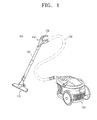
- FIG. 1 is a perspective view of a vacuum cleaner according to an exemplary embodiment of the present invention.
- a vacuum cleaner includes a brush assembly 110, a brush pipe 120, a flexible hose 130, a cleaner body 140, and a handle assembly 150.
- the brush assembly 110 contacts a surface to be cleaned, and draws in dust-laden air from the surface.
- the drawn dust-laden air is transferred to the cleaner body 140 through the brush pipe 120 extending from the brush assembly 110, and through the flexible hose 130.
- a dust separating unit (not shown) mounted in the cleaner body 140 separates dust or other matter from air drawn in through the brush assembly 110.
- a motor (not shown) is mounted in the cleaner body 140 to generate a suction force to draw dust-laden air into the vacuum cleaner body 140 through the brush assembly 110.
- the handle assembly 150 is disposed between the brush pipe 120 and the flexible hose 130.
- a user grips a handle 170 provided on the handle assembly 150, and manipulates the brush pipe 120 and the brush assembly 110 in order to clean the surface being cleaned.
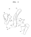
- FIG. 2 is an exploded perspective view of the handle assembly 150
- FIG. 3 is a cross-sectional side view of the handle assembly 150
- FIG. 4 is a cross-sectional plane view of the handle assembly 150.
- the handle assembly 150 includes a housing 160, the handle 170, a connection unit 180, and an elastic unit 190.
- the housing 160 forms an outward of the handle assembly 150.
- the handle 170 is rotatable in all directions, including left, right, up, and down, and may be gripped by a user in order to move the vacuum cleaner.
- connection unit 180 connects the housing 160 with the handle 170 capable of rotating in all directions.
- the connection unit 180 includes a shaft 181 and a guide unit 183.
- the shaft 181 is formed to penetrate the handle 170, and the handle 170 is able to rotate up or down about the shaft 181.
- the guide unit 183 houses the shaft 181, in which the shaft 181 is capable of rotating, and the guide unit 183 is housed in the housing 160.
- the shaft 181 slidingly rotates in the guide unit 183, and the handle 170 is able thereby to rotate in left and right.
- the shaft 181 and guide unit 183 support the handle 170 to rotate in all directions, including left, right, up, and down.
- the connection unit 180 disclosed above is provided as example in the exemplary embodiment of the present invention, but the connection unit 180 may have various forms, and only needs to connect the handle 170 so that the handle 170 is capable of rotating in all directions, including left, right, up, and down.
- a user may grasp the handle 170 in various positions without moving the brush pipe 120. Therefore, the angle at which a user's wrist or elbow is bent while performing cleaning is reduced. Accordingly, the user feels less strain and may use the brush pipe 120 more conveniently.
- the elastic unit 190 elastically biases the handle 170 to a neutral position. In the neutral position, the handle 170 does not rotate at all in any direction, and is located at the center of the housing 160. That is, if the handle 170 is in the neutral position, the elastic unit 190 applies a net force of 0N to the handle 170.
- the elastic unit 190 according to the exemplary embodiment of the present invention includes four elastic members 191, 192, 193, and 194 which are in contact with the handle 170.
- the elastic member 191 elastically biases the handle 170 to the neutral position
- the elastic member 192 elastically biases the handle 170 to the neutral position
- the elastic member 193 elastically biases the handle 170 to the neutral position
- the elastic member 194 elastically biases the handle 170 to the neutral position.
- the elastic members 191, 192, 193, and 194 are formed as leaf springs.
- the present invention should not be considered to be limited to such a configurations, and the elastic members 191, 192, 193, and 194 may alternatively be torsion springs, or compression springs.
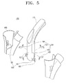
- FIG. 5 is an exploded perspective view of a handle assembly according to an exemplary embodiment of the present invention.
- the handle assembly 150 of FIG. 5 is substantially identical to that of FIG. 2 , except that the handle assembly 150 of FIG. 5 additionally includes a flange 182 formed at both ends of the shaft 181.
- the flange 182 corresponds to the guide unit 183 in cross-section, and thus the flange 182 may be inserted into the guide unit 183, and is capable of sliding therein.
- the shaft 181 is able to rotate, and the handle 170 is able to move to the left and right.
- FIG. 6 is a plane view illustrating the state of the vacuum cleaner while in use according to an exemplary embodiment of the present invention.
- the handle 170 rotates to the left and right, so a user can conveniently clean corners (A). If the handle 170 is fixedly connected to the brush pipe 120, a user should move his or her arm to the position shown in the dotted line to clean the corner (A). However, as the handle 170 of the vacuum cleaner according to the exemplary embodiment of the present invention is rotatable to the left and right, it is unnecessary for a user to move to the corner (A). The user can conveniently handle the brush pipe 120 by using the vacuum cleaner according to the exemplary embodiment of the present invention.
- FIG. 7 is a side view illustrating the vacuum cleaner of FIG. 1 while in use.
- a user should move the brush pipe 120 vigorously in order to clean a corner (B).
- the handle 170 is fixedly connected to the brush pipe 120, the user should bend his or her wrist or elbow to an inconvenient position.
- the handle 170 of the vacuum cleaner according to the exemplary embodiment of the present invention is rotatable up and down. Accordingly, even when the brush pipe 120 is bent at an extreme angle, the angle between the handle 170 and the surface hardly varies. That is, the angle ⁇ 1 between the handle 170 and the surface when the brush assembly is positioned as shown by the solid line is approximately the same as the angle ⁇ 2 between the handle 170 and the surface when the brush assembly is positioned as shown by the dotted line. Accordingly, a user can conveniently clean the corner (B) without substantial wrist and elbow movement.
- the handle rotates in all directions, including left, right, up, and down. Therefore, the user's wrist and elbow are bent at a slight angle, and the user feels less strain in his or her joints.
- a user can thus handle the brush pipe conveniently by rotating the handle.
Landscapes
- Engineering & Computer Science (AREA)
- Mechanical Engineering (AREA)
- Electric Vacuum Cleaner (AREA)
Abstract
Description
- This application claims priority under 35 U.S.C. § 119 from Korean Patent Application No.
10-2007-0134708, filed on December 20, 2007 - The present disclosure relates to a vacuum cleaner, and more particularly, to a handle assembly rotatable in all directions and a vacuum cleaner having the same.
- A general cleaner includes a cleaner body, a brush assembly, a brush pipe, a flexible suction hose, and a handle assembly. The cleaner body generates a suction force for sucking dust-laden air by driving a motor mounted therein. The brush assembly travels along a surface being cleaned, and draws in dust-laden air from the surface. The drawn dust-laden air is transferred to a dust separating apparatus mounted in the cleaner body through the brush pipe extending from the brush assembly. The brush pipe is connected to the cleaner body using the flexible hose, which enables a user to conveniently clean an area. The handle assembly is mounted between the brush pipe and the suction hose, and includes a handle which a user may grip to manipulate the brush assembly. The user may clean a surface by gripping the handle and moving the brush assembly.
- The cleaner handle is generally fixed in place, and thus does not rotate. That is, the cleaner handle is fixed to a brush pipe, so the cleaner handle moves along with the brush pipe. When a user cleans corners, the user may experience inconvenience in handling the long brush pipe, since the user needs to bend his or her wrist or elbow.
- To solve the above problems, vacuum cleaners having a handle rotatable in a certain direction was disclosed. However, such vacuum cleaners also have the above problems, since the handle rotates in only one direction.
- An aspect of the present disclosure is to address at least the above problems and/or disadvantages and to provide at least the advantages described below. Accordingly, an aspect of the present disclosure is to provide a handle assembly rotatable in all directions.
- Another aspect of the present disclosure is to provide a vacuum cleaner having the handle assembly.
- According to an exemplary aspect of the present invention, there is provided a handle assembly, including a housing; a handle which is capable of being gripped by a user; a connection unit which connects the housing with the handle to rotate in all directions; and an elastic unit which elastically biases the handle to a neutral position.
- The connection unit may include a shaft which penetrates the handle; and a guide unit which houses the shaft in a rotatable manner.
- The connection unit may further include a flange which is inserted into the guide unit, and is formed at both ends of the shaft.
- The elastic unit may include four elastic members which are in contact with the handle.
- The elastic member may be a leaf spring.
- The elastic member may be a torsion spring.
- The elastic member may be a compression spring.
- According to an exemplary aspect of the present invention, there is provided a cleaner, including a brush assembly which contacts a surface being cleaned, and draws in dust-laden air from the surface; a brush pipe which extends from the brush assembly; and a handle assembly which is mounted on an end of the brush pipe, wherein the handle assembly includes a housing; a handle which is capable of being gripping by a use; a connection unit which connects the housing to the handle to rotate in all directions; and an elastic unit which elastically biases the handle to a neutral position.
- The above and/or other aspects of the present invention will be more apparent by describing certain exemplary embodiments of the present invention with reference to the accompanying drawings, in which:
-
FIG. 1 is a perspective view of a vacuum cleaner according to an exemplary embodiment of the present invention; -
FIG. 2 is an exploded perspective view of a handle assembly according to an exemplary embodiment of the present invention; -
FIG. 3 is a cross-sectional side view of the handle assembly ofFIG. 2 ; -
FIG. 4 is a cross-sectional plane view of the handle assembly ofFIG. 2 ; -
FIG. 5 is an exploded perspective view of a handle assembly according to an exemplary embodiment of the present invention; -
FIG. 6 is a plane view illustrating the state of the vacuum cleaner ofFIG. 1 while in use; and -
FIG. 7 is a side view illustrating the state of the vacuum cleaner ofFIG. 1 while in use. - Certain exemplary embodiments of the present invention will now be described in greater detail with reference to the accompanying drawings.
- In the following description, same drawing reference numerals are used for the same elements even in different drawings. The matters defined in the description, such as detailed construction and elements, are provided to assist in a comprehensive understanding of the invention. Thus, it is apparent that the present invention can be carried out without those specifically defined matters. Also, well-known functions or constructions are not described in detail since they would obscure the invention with unnecessary detail.
-
FIG. 1 is a perspective view of a vacuum cleaner according to an exemplary embodiment of the present invention. - A vacuum cleaner according to an exemplary embodiment of the present invention includes a
brush assembly 110, abrush pipe 120, aflexible hose 130, acleaner body 140, and ahandle assembly 150. - The
brush assembly 110 contacts a surface to be cleaned, and draws in dust-laden air from the surface. The drawn dust-laden air is transferred to thecleaner body 140 through thebrush pipe 120 extending from thebrush assembly 110, and through theflexible hose 130. A dust separating unit (not shown) mounted in thecleaner body 140 separates dust or other matter from air drawn in through thebrush assembly 110. A motor (not shown) is mounted in thecleaner body 140 to generate a suction force to draw dust-laden air into thevacuum cleaner body 140 through thebrush assembly 110. - The
handle assembly 150 is disposed between thebrush pipe 120 and theflexible hose 130. A user grips ahandle 170 provided on thehandle assembly 150, and manipulates thebrush pipe 120 and thebrush assembly 110 in order to clean the surface being cleaned. -
FIG. 2 is an exploded perspective view of thehandle assembly 150,FIG. 3 is a cross-sectional side view of thehandle assembly 150, andFIG. 4 is a cross-sectional plane view of thehandle assembly 150. - The
handle assembly 150 includes ahousing 160, thehandle 170, aconnection unit 180, and anelastic unit 190. - The
housing 160 forms an outward of thehandle assembly 150. - The
handle 170 is rotatable in all directions, including left, right, up, and down, and may be gripped by a user in order to move the vacuum cleaner. - The
connection unit 180 connects thehousing 160 with thehandle 170 capable of rotating in all directions. Theconnection unit 180 includes ashaft 181 and aguide unit 183. - The
shaft 181 is formed to penetrate thehandle 170, and thehandle 170 is able to rotate up or down about theshaft 181. - The
guide unit 183 houses theshaft 181, in which theshaft 181 is capable of rotating, and theguide unit 183 is housed in thehousing 160. Theshaft 181 slidingly rotates in theguide unit 183, and thehandle 170 is able thereby to rotate in left and right. - The
shaft 181 andguide unit 183 support thehandle 170 to rotate in all directions, including left, right, up, and down. Theconnection unit 180 disclosed above is provided as example in the exemplary embodiment of the present invention, but theconnection unit 180 may have various forms, and only needs to connect thehandle 170 so that thehandle 170 is capable of rotating in all directions, including left, right, up, and down. - As the
handle 170 rotates in all directions, including left, right, up, and down, a user may grasp thehandle 170 in various positions without moving thebrush pipe 120. Therefore, the angle at which a user's wrist or elbow is bent while performing cleaning is reduced. Accordingly, the user feels less strain and may use thebrush pipe 120 more conveniently. - The
elastic unit 190 elastically biases thehandle 170 to a neutral position. In the neutral position, thehandle 170 does not rotate at all in any direction, and is located at the center of thehousing 160. That is, if thehandle 170 is in the neutral position, theelastic unit 190 applies a net force of 0N to thehandle 170. Theelastic unit 190 according to the exemplary embodiment of the present invention includes fourelastic members handle 170. - If the
handle 170 rotates upwards, theelastic member 191 elastically biases thehandle 170 to the neutral position, if thehandle 170 rotates downwards, theelastic member 192 elastically biases thehandle 170 to the neutral position, if thehandle 170 rotates to the left, theelastic member 193 elastically biases thehandle 170 to the neutral position, and if thehandle 170 rotates to the right, theelastic member 194 elastically biases thehandle 170 to the neutral position. - In the exemplary embodiment of the present invention, the
elastic members elastic members -
FIG. 5 is an exploded perspective view of a handle assembly according to an exemplary embodiment of the present invention. Thehandle assembly 150 ofFIG. 5 is substantially identical to that ofFIG. 2 , except that thehandle assembly 150 ofFIG. 5 additionally includes aflange 182 formed at both ends of theshaft 181. Theflange 182 corresponds to theguide unit 183 in cross-section, and thus theflange 182 may be inserted into theguide unit 183, and is capable of sliding therein. As theflange 182 is capable of sliding in theguide unit 183, theshaft 181 is able to rotate, and thehandle 170 is able to move to the left and right. -
FIG. 6 is a plane view illustrating the state of the vacuum cleaner while in use according to an exemplary embodiment of the present invention. - Referring to
FIG. 6 , thehandle 170 rotates to the left and right, so a user can conveniently clean corners (A). If thehandle 170 is fixedly connected to thebrush pipe 120, a user should move his or her arm to the position shown in the dotted line to clean the corner (A). However, as thehandle 170 of the vacuum cleaner according to the exemplary embodiment of the present invention is rotatable to the left and right, it is unnecessary for a user to move to the corner (A). The user can conveniently handle thebrush pipe 120 by using the vacuum cleaner according to the exemplary embodiment of the present invention. -
FIG. 7 is a side view illustrating the vacuum cleaner ofFIG. 1 while in use. - Referring to
FIG. 7 , a user should move thebrush pipe 120 vigorously in order to clean a corner (B). If thehandle 170 is fixedly connected to thebrush pipe 120, the user should bend his or her wrist or elbow to an inconvenient position. However, thehandle 170 of the vacuum cleaner according to the exemplary embodiment of the present invention is rotatable up and down. Accordingly, even when thebrush pipe 120 is bent at an extreme angle, the angle between thehandle 170 and the surface hardly varies. That is, the angle θ1 between thehandle 170 and the surface when the brush assembly is positioned as shown by the solid line is approximately the same as the angle θ2 between thehandle 170 and the surface when the brush assembly is positioned as shown by the dotted line. Accordingly, a user can conveniently clean the corner (B) without substantial wrist and elbow movement. - According to the handle assembly of the exemplary embodiment of the present invention, the handle rotates in all directions, including left, right, up, and down. Therefore, the user's wrist and elbow are bent at a slight angle, and the user feels less strain in his or her joints.
- A user can thus handle the brush pipe conveniently by rotating the handle.
- The foregoing exemplary embodiments and advantages are merely exemplary and are not to be construed as limiting the present invention. The present teaching can be readily applied to other types of apparatuses. Also, the description of the exemplary embodiments of the present invention is intended to be illustrative, and not to limit the scope of the claims, and many alternatives, modifications, and variations will be apparent to those skilled in the art.
Claims (14)
- A handle assembly, comprising:a housing;a handle which is capable of being gripped by a user;a connection unit which connects the housing with the handle to rotate in all directions; andan elastic unit which elastically biases the handle to a neutral position.
- The handle assembly of claim 1, wherein the connection unit comprises:a shaft which penetrates the handle; anda guide unit which houses the shaft in a rotatable manner.
- The handle assembly of claim 2, wherein the connection unit further comprises:a flange which is inserted into the guide unit, and is formed at both ends of the shaft.
- The handle assembly of any of the claims 1 to 3, wherein the elastic unit comprises: four elastic members which are in contact with the handle.
- The handle assembly of claim 4, wherein the elastic member is a leaf spring.
- The handle assembly of claim 4, wherein the elastic member is a torsion spring.
- The handle assembly of claim 4, wherein the elastic member is a compression spring.
- A cleaner, comprising:a brush assembly which contacts a surface being cleaned, and draws in dust-laden air from the surface;a brush pipe which extends from the brush assembly; anda handle assembly which is mounted on an end of the brush pipe,wherein the handle assembly comprises:a housing;a handle which is capable of being gripping by a user;a connection unit which connects the housing to the handle to rotate in all directions; andan elastic unit which elastically biases the handle to a neutral position.
- The cleaner of claim 8, wherein the connection unit comprises:a shaft which penetrates the handle; anda guide unit which houses the shaft in a rotatable manner.
- The cleaner of claim 9, wherein the connection unit further comprises:a flange which is inserted into the guide unit, and is formed at both ends of the shaft.
- The cleaner of any of the claims 8 to 10, wherein the elastic unit comprises four elastic members.
- The cleaner of claim 11, wherein the elastic member is a leaf spring.
- The cleaner of claim 11, wherein the elastic member is a torsion spring.
- The cleaner of claim 11, wherein the elastic member is a compression spring.
Applications Claiming Priority (1)
| Application Number | Priority Date | Filing Date | Title |
|---|---|---|---|
| KR1020070134708A KR101462952B1 (en) | 2007-12-20 | 2007-12-20 | A handle assembly rotatable in all directions and a cleaner having the same |
Publications (2)
| Publication Number | Publication Date |
|---|---|
| EP2071997A2 true EP2071997A2 (en) | 2009-06-24 |
| EP2071997A3 EP2071997A3 (en) | 2014-05-07 |
Family
ID=40523971
Family Applications (1)
| Application Number | Title | Priority Date | Filing Date |
|---|---|---|---|
| EP08162113.8A Withdrawn EP2071997A3 (en) | 2007-12-20 | 2008-08-08 | Handle assembly rotatable in all directions and cleaner having the same |
Country Status (5)
| Country | Link |
|---|---|
| US (1) | US7854039B2 (en) |
| EP (1) | EP2071997A3 (en) |
| JP (1) | JP5069627B2 (en) |
| KR (1) | KR101462952B1 (en) |
| RU (1) | RU2470573C2 (en) |
Families Citing this family (18)
| Publication number | Priority date | Publication date | Assignee | Title |
|---|---|---|---|---|
| US8667643B2 (en) | 2010-09-10 | 2014-03-11 | Euro-Pro Operating Llc | Method and apparatus for assisting pivot motion of a handle in a floor treatment device |
| US10016107B2 (en) * | 2011-12-14 | 2018-07-10 | Sharkninja Operating Llc | Surface cleaning apparatus with a sideways pivoting handle |
| US9125538B2 (en) | 2012-07-27 | 2015-09-08 | Techtronic Floor Care Technology Limited | Pivoting handle for a surface cleaning device |
| JP6248667B2 (en) * | 2014-02-07 | 2017-12-20 | 三菱電機株式会社 | Electric vacuum cleaner |
| US9962049B2 (en) | 2014-06-06 | 2018-05-08 | Sharkninja Operating Llc | Surface cleaning apparatus |
| USD762030S1 (en) | 2014-06-12 | 2016-07-19 | Sharkninja Operating Llc | Surface cleaning head for a vacuum cleaner |
| USD742089S1 (en) | 2014-06-27 | 2015-10-27 | Euro-Pro Operations LLC | Caddy |
| USD764125S1 (en) | 2014-06-30 | 2016-08-16 | Sharkninja Operating Llc | Duster |
| GB2542198B (en) * | 2015-09-14 | 2018-01-10 | Dyson Technology Ltd | Handle assembly for a vacuum cleaner |
| GB2542197B (en) * | 2015-09-14 | 2017-12-20 | Dyson Technology Ltd | Handle assembly for a vacuum cleaner |
| USD868406S1 (en) | 2017-07-25 | 2019-11-26 | Sharkninja Operating Llc | Vacuum cleaner tool |
| KR102385783B1 (en) | 2017-08-09 | 2022-04-13 | 삼성전자주식회사 | Handy and stick type vacuum cleaner |
| US11213177B2 (en) | 2017-09-22 | 2022-01-04 | Sharkninja Operating Llc | Hand-held surface cleaning device |
| CN112334050B (en) | 2018-05-09 | 2022-05-24 | 尚科宁家运营有限公司 | Vacuum cleaner, upright vacuum cleaner and multi-axis pivot joint |
| USD873516S1 (en) | 2018-07-30 | 2020-01-21 | Sharkninja Operating Llc | Wand vacuum |
| USD995019S1 (en) | 2020-07-29 | 2023-08-08 | Sharkninja Operating Llc | Vacuum cleaner |
| USD995016S1 (en) | 2020-07-29 | 2023-08-08 | Sharkninja Operating Llc | Vacuum cleaner |
| USD995020S1 (en) | 2020-07-29 | 2023-08-08 | Sharkninja Operating Llc | Vacuum cleaner docking station |
Family Cites Families (16)
| Publication number | Priority date | Publication date | Assignee | Title |
|---|---|---|---|---|
| US4492830A (en) | 1983-03-28 | 1985-01-08 | Wico Corporation | Joystick with single-leaf spring switch |
| KR100470633B1 (en) * | 1995-12-19 | 2005-04-19 | 셀 인터나쵸나아레 레사아치 마아츠샤피 비이부이 | Removal of Metal Compounds from Acid Solutions |
| KR970032728A (en) * | 1995-12-29 | 1997-07-22 | 배순훈 | Rotating hose handle structure of vacuum cleaner |
| JP2853027B2 (en) * | 1996-03-29 | 1999-02-03 | 株式会社スギヤマエレクトロン | Joystick for keyboard |
| KR100213651B1 (en) * | 1997-07-16 | 1999-08-02 | 최진호 | Bendable device for vacuum cleaner handle |
| KR100213652B1 (en) * | 1997-07-16 | 1999-08-02 | 최진호 | Vacuum cleaner having a tiltable handle |
| JP3296777B2 (en) * | 1998-03-17 | 2002-07-02 | 株式会社日立製作所 | Electric vacuum cleaner |
| JPH11146851A (en) | 1997-11-17 | 1999-06-02 | Hitachi Ltd | Vacuum cleaner and hand-side handle |
| KR20000061312A (en) | 1999-03-25 | 2000-10-16 | 윤종용 | Image printing apparatus and method of driving the same |
| KR100640927B1 (en) | 2000-09-05 | 2006-11-02 | 엘지전자 주식회사 | vacuum cleaner having rotative handle |
| KR100504469B1 (en) * | 2002-06-29 | 2005-08-03 | 엘지전자 주식회사 | Joint Structure of Revolving Type of Handle in Vacuum Cleaner |
| JP2005110859A (en) * | 2003-10-06 | 2005-04-28 | Toshiba Tec Corp | Vacuum cleaner |
| KR20050057795A (en) * | 2003-12-11 | 2005-06-16 | 엘지전자 주식회사 | A structure of hose handle for vacuum cleaner |
| CA2524595A1 (en) * | 2004-11-04 | 2006-05-04 | The Hoover Company | Portable cleaning machine |
| US20070214598A1 (en) * | 2006-03-15 | 2007-09-20 | Zahuranec Terry L | Force sensor |
| US20080016632A1 (en) * | 2006-07-20 | 2008-01-24 | Ing. Haaga Werkzeugbau Gmbh & Co. Kg | Pushing Handle |
-
2007
- 2007-12-20 KR KR1020070134708A patent/KR101462952B1/en not_active IP Right Cessation
-
2008
- 2008-05-14 US US12/153,178 patent/US7854039B2/en not_active Expired - Fee Related
- 2008-07-24 JP JP2008190692A patent/JP5069627B2/en not_active Expired - Fee Related
- 2008-08-07 RU RU2008132418/12A patent/RU2470573C2/en not_active IP Right Cessation
- 2008-08-08 EP EP08162113.8A patent/EP2071997A3/en not_active Withdrawn
Non-Patent Citations (1)
| Title |
|---|
| None * |
Also Published As
| Publication number | Publication date |
|---|---|
| KR20090066957A (en) | 2009-06-24 |
| KR101462952B1 (en) | 2014-11-20 |
| US7854039B2 (en) | 2010-12-21 |
| RU2470573C2 (en) | 2012-12-27 |
| EP2071997A3 (en) | 2014-05-07 |
| JP2009148537A (en) | 2009-07-09 |
| JP5069627B2 (en) | 2012-11-07 |
| RU2008132418A (en) | 2010-02-20 |
| US20090158550A1 (en) | 2009-06-25 |
Similar Documents
| Publication | Publication Date | Title |
|---|---|---|
| US7854039B2 (en) | Handle assembly rotatable in all directions and cleaner having the same | |
| US7950102B2 (en) | Upright vacuum cleaner having steering unit | |
| CN111031872B (en) | Vacuum cleaner | |
| US20130086768A1 (en) | Upright floor surface treating apparatus | |
| EP1795105B1 (en) | Vacuum cleaner | |
| US7559112B2 (en) | Passage conversion valve assembly for a vacuum cleaner | |
| JP6229169B2 (en) | Vacuum cleaner suction tool and vacuum cleaner provided with the same | |
| RU2462983C1 (en) | Assembly of electric vacuum cleaner hose and electric vacuum cleaner | |
| EP2992800B1 (en) | Vacuum cleaner | |
| JP5118013B2 (en) | Electric vacuum cleaner | |
| EP2103242B1 (en) | Brush assembly and vaccum cleaner having the same | |
| JPH05161580A (en) | Vacuum cleaner | |
| JP4650184B2 (en) | Electric vacuum cleaner | |
| JP6056377B2 (en) | Electric vacuum cleaner | |
| CN112533519B (en) | Vacuum cleaner nozzle and vacuum cleaner | |
| JP4726708B2 (en) | Vacuum cleaner | |
| JP6632875B2 (en) | Electric vacuum cleaner | |
| JP2005211674A (en) | Suction device for electric vacuum cleaner and electric vacuum cleaner | |
| KR20070063701A (en) | A vacuum cleaner | |
| KR20070066144A (en) | Cleaner | |
| JP2007111158A (en) | Vacuum cleaner | |
| JP2010162081A (en) | Vacuum cleaner |
Legal Events
| Date | Code | Title | Description |
|---|---|---|---|
| PUAI | Public reference made under article 153(3) epc to a published international application that has entered the european phase |
Free format text: ORIGINAL CODE: 0009012 |
|
| AK | Designated contracting states |
Kind code of ref document: A2 Designated state(s): AT BE BG CH CY CZ DE DK EE ES FI FR GB GR HR HU IE IS IT LI LT LU LV MC MT NL NO PL PT RO SE SI SK TR |
|
| AX | Request for extension of the european patent |
Extension state: AL BA MK RS |
|
| RAP1 | Party data changed (applicant data changed or rights of an application transferred) |
Owner name: SAMSUNG ELECTRONICS CO., LTD. |
|
| RAP1 | Party data changed (applicant data changed or rights of an application transferred) |
Owner name: SAMSUNG ELECTRONICS CO., LTD. |
|
| PUAL | Search report despatched |
Free format text: ORIGINAL CODE: 0009013 |
|
| AK | Designated contracting states |
Kind code of ref document: A3 Designated state(s): AT BE BG CH CY CZ DE DK EE ES FI FR GB GR HR HU IE IS IT LI LT LU LV MC MT NL NO PL PT RO SE SI SK TR |
|
| AX | Request for extension of the european patent |
Extension state: AL BA MK RS |
|
| RIC1 | Information provided on ipc code assigned before grant |
Ipc: A47L 11/40 20060101ALI20140402BHEP Ipc: A47L 9/32 20060101AFI20140402BHEP |
|
| 17P | Request for examination filed |
Effective date: 20141103 |
|
| RBV | Designated contracting states (corrected) |
Designated state(s): AT BE BG CH CY CZ DE DK EE ES FI FR GB GR HR HU IE IS IT LI LT LU LV MC MT NL NO PL PT RO SE SI SK TR |
|
| AKX | Designation fees paid |
Designated state(s): DE FR GB IT |
|
| AXX | Extension fees paid |
Extension state: AL Extension state: RS Extension state: MK Extension state: BA |
|
| 17Q | First examination report despatched |
Effective date: 20180130 |
|
| STAA | Information on the status of an ep patent application or granted ep patent |
Free format text: STATUS: THE APPLICATION IS DEEMED TO BE WITHDRAWN |
|
| 18D | Application deemed to be withdrawn |
Effective date: 20180612 |