JP6248667B2 - Electric vacuum cleaner - Google Patents
Electric vacuum cleaner Download PDFInfo
- Publication number
- JP6248667B2 JP6248667B2 JP2014022251A JP2014022251A JP6248667B2 JP 6248667 B2 JP6248667 B2 JP 6248667B2 JP 2014022251 A JP2014022251 A JP 2014022251A JP 2014022251 A JP2014022251 A JP 2014022251A JP 6248667 B2 JP6248667 B2 JP 6248667B2
- Authority
- JP
- Japan
- Prior art keywords
- hand handle
- vacuum cleaner
- cover
- branch
- tube
- Prior art date
- Legal status (The legal status is an assumption and is not a legal conclusion. Google has not performed a legal analysis and makes no representation as to the accuracy of the status listed.)
- Active
Links
- 239000011347 resin Substances 0.000 claims description 7
- 229920005989 resin Polymers 0.000 claims description 7
- 238000005452 bending Methods 0.000 claims description 4
- 239000007769 metal material Substances 0.000 claims description 2
- 239000011358 absorbing material Substances 0.000 claims 1
- 239000000428 dust Substances 0.000 description 32
- 238000000465 moulding Methods 0.000 description 10
- 210000000078 claw Anatomy 0.000 description 9
- 239000000758 substrate Substances 0.000 description 7
- 238000004891 communication Methods 0.000 description 4
- 238000000926 separation method Methods 0.000 description 3
- 238000012790 confirmation Methods 0.000 description 2
- 230000000694 effects Effects 0.000 description 2
- 238000004898 kneading Methods 0.000 description 2
- 239000000463 material Substances 0.000 description 2
- XAGFODPZIPBFFR-UHFFFAOYSA-N aluminium Chemical compound [Al] XAGFODPZIPBFFR-UHFFFAOYSA-N 0.000 description 1
- 238000004140 cleaning Methods 0.000 description 1
- 239000011248 coating agent Substances 0.000 description 1
- 238000000576 coating method Methods 0.000 description 1
- 230000008602 contraction Effects 0.000 description 1
- 230000007547 defect Effects 0.000 description 1
- 229920001971 elastomer Polymers 0.000 description 1
- 239000000806 elastomer Substances 0.000 description 1
- 238000000034 method Methods 0.000 description 1
- 239000012778 molding material Substances 0.000 description 1
- 239000000843 powder Substances 0.000 description 1
- 230000008439 repair process Effects 0.000 description 1
- 238000007493 shaping process Methods 0.000 description 1
Images


Description
本発明は、手元ハンドル体を有する電気掃除機に関するものである。 The present invention relates to a vacuum cleaner having a hand handle body.
従来からキャニスタータイプの電気掃除機において、被清掃面から集塵した塵埃を含む気流が流れる管体と、この管体から離れた位置に、使用者が握る部位である把持部を設けた手元ハンドルがある(例えば、特許文献1参照)。 Conventionally, in a canister type electric vacuum cleaner, a hand handle that is provided with a tubular body through which an air flow including dust collected from the surface to be cleaned flows, and a gripping portion that is a part gripped by a user at a position away from the tubular body (For example, refer to Patent Document 1).
このような従来の電気掃除機の手元ハンドル体は樹脂により成形され、持ちやすい把持部の形状を形成するために、曲面や分岐部分や開口、また、部品を搭載する搭載位置となる部位を有する。
このような手元ハンドル体を成形する際に、成形金型内部のこれらの部位を形成する位置では、樹脂材料に流れムラが生じやすく、成形品の表面に外観不良であるフローマーク(ウエルドライン)が出てしまうことがある。
また、把持部及びこの把持部が分岐する管体の剛性を確保するために、表面に突出するリブを形成する必要があり、意匠のデザインに制約が出てしまうという課題がある。
The hand handle body of such a conventional vacuum cleaner is molded from resin, and has a curved surface, a branching portion, an opening, and a portion to be a mounting position for mounting components in order to form a shape of a grip portion that is easy to hold. .
When molding such a hand handle body, a flow mark (weld line) is likely to cause uneven flow of the resin material at the position where these parts are formed inside the molding die, and the appearance of the molded product is poor. May come out.
Moreover, in order to ensure the rigidity of a holding part and the pipe body from which this holding part branches, it is necessary to form the rib which protrudes on the surface, and there exists a subject that the design of a design will become restrictions.
本発明は、上記のような課題を解決する為になされたもので、意匠性にすぐれた手元ハンドル体を有する電気掃除機を提供することを目的とする。 The present invention has been made to solve the above-described problems, and an object of the present invention is to provide a vacuum cleaner having a hand handle body excellent in design.
上記の課題を解決するには、内部に電動送風機を設けた本体と、一端が前記本体に接続される吸引ホースと、この吸引ホースの他端に取り付けられる手元ハンドル体を有する電気掃除機において、手元ハンドル体は、吸引ホースと連通する風路を形成する管体と、この管体から分岐し把持部が形成される分岐部と、少なくともこの分岐部の側面を覆う側面カバーと、分岐部の上面を覆う上面カバーと、を有し、上面カバーは、より前記分岐部にねじにより固定され、側面カバーは、管体から分岐部の側面を経て分岐部の上面に至るように取り付けられ、上面カバーを分岐部に固定するねじを上方から覆うように構成すればよい。
In order to solve the above problem, in a vacuum cleaner having a main body provided with an electric blower inside, a suction hose having one end connected to the main body, and a hand handle body attached to the other end of the suction hose, The hand handle body includes a tube body forming an air passage communicating with the suction hose, a branch portion branched from the tube body to form a grip portion, a side cover covering at least a side surface of the branch portion, and a branch portion An upper surface cover that covers the upper surface, the upper surface cover is further fixed to the branch portion with screws, and the side surface cover is attached so as to reach the upper surface of the branch portion from the tubular body through the side surface of the branch portion. What is necessary is just to comprise so that the screw which fixes a cover to a branch part may be covered from upper direction .
本発明によれば、外観意匠性を高めた手元ハンドル体を有する電気掃除機を得ることができる。 ADVANTAGE OF THE INVENTION According to this invention, the vacuum cleaner which has a hand handle body which improved the external appearance design property can be obtained.
(実施の形態1)
以下、図1〜図11を参照して実施の形態1を説明する。
まず、図1〜図2を参照して、電気掃除機1について説明する。
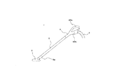
図1は、実施の形態1における電気掃除機1を示す斜視図である。図2は、吸込口体6からホース3に至る部位の側面図である。
(Embodiment 1)
The first embodiment will be described below with reference to FIGS.
First, the vacuum cleaner 1 will be described with reference to FIGS.
FIG. 1 is a perspective view showing a vacuum cleaner 1 according to the first embodiment. FIG. 2 is a side view of a portion from the suction port body 6 to the
図1〜図2に示すように、電気掃除機1は、本体(掃除機本体)2、ホース3、手元ハンドル体4、延長管5、吸込口体6を備える。
吸込口体6は、下向きに形成された開口から、床面上のごみ(塵埃)を空気と一緒に内部に取り込む部位である。この吸込口体6の吸気側の端部には、次に説明する延長管5に接続する接続管6aが設けられている。
As shown in FIGS. 1 to 2, the vacuum cleaner 1 includes a main body (cleaner main body) 2, a
The suction port body 6 is a part that takes in dust (dust) on the floor surface into the inside together with air from an opening formed downward. A connection pipe 6 a that is connected to an
次に延長管5は、後述する手元ハンドル体4に接続する集塵接続体の1つであり、全体として真直ぐな円筒状を呈する。延長管5の一端部は吸込口体6の接続管6aに接続し、他端部は手元ハンドル体4に接続する。
使用者は、延長管5に設けられたボタン5aの操作を行うことにより、吸込口体6を延長管5から取り外すことができる。
Next, the
The user can remove the suction port body 6 from the
延長管5は、吸気側の端部にブラシ5cを備える。このブラシ5cは、吸込口体6を外した状態で被清掃面に接触させて使用するもので、延長管5の吸気側の開口周辺に移動可能である。
使用者は、延長管5の排気側の端部に設けられた伸縮ボタン5bを操作することにより、延長管5を伸縮させることができる。
The
The user can expand and contract the
ここでは、手元ハンドル体4に接続される集塵接続体の例として、延長管5について説明したが、この他に、先端が窄んだ形状に構成され狭い部分の塵埃を吸い取りやすく構成されたノズルや、先端に毛ブラシが植毛され隙間などの塵埃を書き出しやすく構成されたブラシ等も、集塵接続体である。
また、吸込口体6も、延長管5に取り付けることで、間接的に手元ハンドル体4に取り付けられることから集塵接続体である。
Here, the
The suction port body 6 is also a dust collecting connection body because it is indirectly attached to the
次に、手元ハンドル体4は、掃除を行う時に使用者が持つ部分であり、操作体となる部位である。使用者は、手元ハンドル体4を持ち、この手元ハンドル体4を操作して、集塵接続体を被清掃面に向けて落ちている塵埃を吸引する。
例えば、本実施の形態の場合、使用者は、手元ハンドル体4を操作して、延長管5に取り付けた吸込口体6の位置及び向きを変える。手元ハンドル体4の吸気側の端部(吸込み側開口41)は、延長管5の排気側端部に接続する。
使用者は、手元ハンドル4に設けられた解除ボタン4aを操作することにより、延長管5を手元ハンドル体4から取り外すことができる。手元ハンドル体4は、吸気側の端部に、延長管5を取り外した状態で使用するためのブラシ400を備える。
Next, the
For example, in the case of the present embodiment, the user operates the
The user can remove the
次に、ホース3は、要部が、可撓性を備えた蛇腹状である中空の部材からなる。ホース3の吸気側の端部は、手元ハンドル体4に接続される。ホース3は、排気側の端部は、硬質の接続部3aを備え、この接続部3aが本体2に接続される。
本体2は、ホース3の接続部3aが接続され、ごみを含む空気(含塵空気)からごみを分離する。この本体2は、後部に開口する排気口(図示せず)より、塵埃が取り除かれた空気(清浄空気)を排出する。空気から分離したごみは、本体2の内部に溜められる。
以上のように各部が接続されることで、吸込口体6や延長管5などの集塵接続体から、手元ハンドル体4、ホース3、そして、本体2へと至る一続きの風路Fが形成される。
Next, the
The
By connecting each part as described above, a continuous air passage F from the dust collecting connection body such as the suction port body 6 and the
次に、本体2は内部に、電動送風機11、集塵部12を備える。
電動送風機11は、電気掃除機1に形成された風路Fに、吸込み側である集塵接続体から排気側である排気口に向けて本体2内部に流下する気流を発生させる。
この電動送風機11が吸引動作を行うと、床面上のごみが空気と一緒に吸込口体6に吸い込まれる。吸込口体6に吸い込まれた含塵空気は、吸込口体6、延長管5、手元ハンドル体4、ホース3の各内部を通り、本体2に送られる。
Next, the
The electric blower 11 generates an airflow that flows down in the
When the electric blower 11 performs a suction operation, the dust on the floor surface is sucked into the suction port body 6 together with the air. The dust-containing air sucked into the suction port body 6 passes through each of the suction port body 6, the
集塵部12は、本体2の内部に流入したごみを空気(気流)から分離する。集塵部12は、空気から分離したごみを捕捉する。図1は、集塵部12の一例として、紙パック式の分離装置を示している。集塵部12として、サイクロン式の分離装置や他の方式の分離装置を採用してもよい。
The dust collecting unit 12 separates dust flowing into the
また、本体2は、両側に大型の車輪13を、下面に小型の車輪(図示せず)を備える。小型の車輪は、その向きを自在に変えることができるように取り付けられている。このため、本体2は、車輪13及び小型の車輪が床面に接触した状態で向きを変えることができる。
Further, the
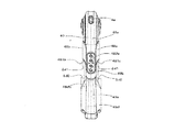
次に、本実施の形態の要部である手元ハンドル体4について、図3〜図13を参照して説明する。
図3〜図5を参照すると、手元ハンドル体4は、風路Fの一部を構成し基部となる管体40と、この管体40から分岐するように設けられる分岐部44と、管体40と分岐部44の外郭を被う各カバー48から構成される。
管体40は、吸気側開口41から排気側方向に向けて直線的に伸び、中ほどの位置(曲がり位置43)から下斜め後ろ方向に折れ曲がり排気側開口42に向けて直線的に伸びる形状を成している。
Next, the hand handle
Referring to FIGS. 3 to 5, the
The
管体40の曲がり位置43の後ろ側の上方には、分岐部44が設けられる。
この分岐部44は、管体40の上面の分岐位置45から上斜め後方に向けて延びる分岐前部44aと、この分岐前部44aの後ろ側から湾曲して下斜め後方に延び分岐後端44cに至る分岐後部44bから成り、分岐位置45から分岐後端44cに掛けてアーチ形状を成している。
尚、管体40と分岐部44は、樹脂成形により一体に形成されている。
A
The
The
そして、図5〜図7を参照すると、分岐前部44aの上面には、管体40と分岐部44の分岐している位置から分岐前部44aの後端に掛けて、左右一対の壁部44eが形成されている。
そして、この左右の壁面44eの間には、上面凹部44gが形成される。この上面凹部44gは、上方に向けて開口しており、凹部内部に、電動送風機のON/OFFや出力の変更を行う操作スイッチ46aや、手元ハンドル体4の動きや振動を検知するモーションセンサー46bを実装した基板46が設けられる。
5 to 7, on the upper surface of the branch front portion 44a, a pair of left and right wall portions are hung from the branching position of the
An upper surface recess 44g is formed between the left and right wall surfaces 44e. The upper surface recess 44g is open upward, and an operation switch 46a for turning on / off the electric blower and changing the output and a motion sensor 46b for detecting the movement and vibration of the
また、左右の壁面44gには、それぞれ、後述する上カバー48aの係合爪が係合する第1の係合開口44hと、後述する左右カバー48b,48cの係合爪482b,482cが係合する第2の係合開口44iが形成されている。
また、吸気側開口41から分岐部44に至る管体40の上面には、非接触で外部機器との通信を行う通信手段47と、吸気側開口41に接続された集塵接続体を外す解除ボタン4aが設けられる。
これら基板46及び通信手段47のいずれも、本体2に設けられた電気掃除機1の各部を制御する制御手段(図示せず)に電気的に接続され、信号を制御手段に出力する。
Further, the left and right wall surfaces 44g are respectively engaged with
In addition, on the upper surface of the
Both of the
次に、図6〜図8を参照すると、管体40の側面には、管体40の伸びる方向に帯状に突出した管体リブ40bが形成されている。この管体リブ40bは、分岐部44が接続する位置の下側に位置しており、管体40の剛性を高めるためのものである。
また、分岐部44の側面には、管体40から分岐前部44aの端に向けて帯状に突出して伸びる分岐部リブ44jが形成されている。この分岐部リブ44jは、分岐部44の剛性を高めるためのものである。
そして、排気側開口42には、ホース3の開口内部に管体40を挿入することにより、ホース3が接続する。
Next, referring to FIG. 6 to FIG. 8,
Further, on the side surface of the branching
The
次に、図6〜図7を参照すると、以上ように各部が構成された管体40及び分岐部44の外郭には、次の各カバー48が取り付けられ手元ハンドル体4の外観を形成する。
カバー48は、上カバー48aと、左側面カバー48bと、右側面カバー48cと、左後側面カバー48dと、右後側面カバー48eで構成されている。これらのカバーは、樹脂成形により形成されている。
Next, referring to FIG. 6 to FIG. 7, the following covers 48 are attached to the outside of the
The cover 48 includes an
まず、上カバー48aは、吸引側開口41から分岐部44の上面を被うカバーであり、解除ボタン4aが臨むボタン開口481aと、基板46に実装された操作スイッチに対向する位置に操作スイッチ押圧部482aが形成されている。
操作スイッチ押圧部482aは、表面に電動送風機の出力を変化させる旨を意味する「矢印マーク」、「ON/OFF」、「エコモード」等の表示がなされており、当該位置を使用者が押圧することで、対応する操作スイッチが押されて、制御手段に信号が発信される。制御手段はこれらの信号に基づき、電動送風機の出力を制御する。
First, the
The operation
このように構成された上カバー48aは、分岐部44に形成された第1の係合開口44hに係合爪483aが係合する。
そして、上カバー48aに開口するねじ開口485aに、上方よりねじ484aを通して、分岐部44の上面に形成されたねじ穴44dにねじ止めすることにより、吸引側開口41から分岐部44の上面を被った状態で管体40に取り付け固定される。
上カバー48aが上記の通り取り付けられた状態において、分岐後部44bの下面441bと、この分岐後部44bの上面を被う上カバー48aの上面486aにより、使用者が握る位置となる第1の把持部49aが形成される。
In the
Then, the
In a state where the
次に、左側面カバー48bは、管体40の下面から左側面に至り、分岐前部44aの左側面を経て、分岐部44の上面左側まで至る管体40と分岐部44を覆うカバーである。
この左側面カバー48bの裏面には、複数の係合爪482bが設けられている。この係合爪482bが、管体40の下面に設けられた管体係合開口40c、及び、分岐部44に形成された第2の係合開口44iに係合することにより、管体40から分岐部44に渡って取り付けられる。
Next, the
A plurality of engagement claws 482b are provided on the back surface of the
この左側面カバー48bは、管体40の表面に取り付けられることから、管体40の外面より左側面カバー48bの厚みΔd1分、外側に突出した外郭を形成する。つまり、管体40と左側面カバー48bとの間に高さがΔd1の段差が形成される(図11参照)。
Since the
ここで、左側面カバー48bは、上カバー48aが分岐部44に取り付けた後に取り付けられる。これにより、左側面カバー48bの取り付け前に、第2の係合開口44iから、基板46の取り付け位置である凹部44gを確認することができる。
つまり、第2の係合開口44iは、基板46が取り付けられたか否かを確認する開口として用いることができる。尚、この確認用の開口は、第2の係合開口44iとは、別途形成しても良い。
Here, the
That is, the second engagement opening 44i can be used as an opening for confirming whether or not the
次に、右側面カバー48cは、管体40の下面から右側面に至り、分岐前部44aの右側面を経て、分岐部44の上面右側まで至る管体40と分岐部44を覆うカバーである。
この右側面カバー48cの裏面には、複数の係合爪482cが設けられている。この係合爪482cが、管体40の下面に設けられた管体係合開口40c、及び、分岐部44に形成された第2の係合開口44iに係合することにより、管体40から分岐部44に渡って取り付けられる。
Next, the right side cover 48c is a cover that covers the
A plurality of engaging
この右側面カバー48cは、管体40の表面に取り付けられることから、管体40の外面より右側面カバー48cの厚みΔd1分、外側に突出した外郭を形成する。つまり、管体40と右側面カバー48cとの間に高さがΔd1の段差が形成される(図11参照)。
Since the right side cover 48c is attached to the surface of the
ここで、右側面カバー48cは、上カバー48aが分岐部44に取り付けた後に取り付けられる。これにより、左側面カバー48cの取り付け前に、第2の係合開口44iから、基板46の取り付け位置である凹部44gを確認することができる。
つまり、第2の係合開口44iは、基板46が取り付けられたか否かを確認する開口として用いることができる。尚、この確認用の開口は、第2の係合開口44iとは、別途形成しても良い。
Here, the right side cover 48 c is attached after the
That is, the second engagement opening 44i can be used as an opening for confirming whether or not the
以上の左側面カバー48bと右側面カバー48cは、互いに対称となる形状で構成されおり、これらを上記の通り取り付けることで、管体40の下側と分岐部44の上側の位置において、左側面カバー48bと右側面カバー48cが合わさる形状となっている。
従って、左右側面カバー48b,48cが管体40及び分岐部44に取り付けられることで、管体40及び分岐部44の表面に形成された管体リブ40b及び分岐部44を覆い隠し、手元ハンドル体4の一方の側面から他方の側面に連続的に至る外観意匠面を形成する。
The
Accordingly, the left and right side covers 48b and 48c are attached to the
以上の手元ハンドル体4において、上記の通り、管体40及び分岐部44と左右側面カバー48b,48cを別部材にすることで、左右側面カバー48b,48cに傷や汚れがついても、容易にカバーを交換することができる。
特に、手元ハンドル体4は後ろ端にホース3が設けられるので、手元ハンドル体4を落とした場合、床面と接触するのは左右側面カバー48b,48cである可能性が高いことから、傷のついた側面カバーの交換のみで、傷やよごれに対応する修理が済む。
In the
In particular, since the
更に、左右側面カバー48b,48cは、意匠面となる表面は急な曲面や角となる部位や開口が開いていない緩やかな曲面であることから、フローマーク(成形不良)が起こり難い。従って、左右側面カバー48b,48cを成形する際に、成形材料である樹脂に、意匠性を向上させる材料(例えば、光を反射して輝きを見せるメタリック材料(アルミ粉末やパール粉末)など)を練り込み成形する手法(以下、練りみ成形)を用いることができる。
これにより、成形時にフローマークが起こりやすい複雑な形状の部位を有する手元ハンドル体4であっても、樹脂成形で塗装に近い質感である外観意匠を得ることができる。
Furthermore, the left and right side covers 48b and 48c have steep curved surfaces, corner portions, and gently curved surfaces with no openings, so that flow marks (molding defects) are unlikely to occur. Therefore, when molding the left and right side covers 48b and 48c, a material that improves designability (for example, a metallic material (such as aluminum powder or pearl powder) that reflects light to show a shine) is applied to the resin that is a molding material. A method of kneading and molding (hereinafter, kneading molding) can be used.
Thereby, even if it is the
また、この左右側面カバー48b,48cをエラストマー等の軟質部材で構成すれば、手元ハンドル体4を落下させたとき、手元ハンドル体4が受ける衝撃を和らげることができる。
Further, if the left and right side covers 48b, 48c are made of a soft member such as an elastomer, the impact received by the
また、図10を参照すると、分岐部44の上側の合わせ位置において、左側面カバー48bと右側面カバー48cの合わせ位置の下側には、分岐部44の上面に形成されたねじ穴44dが位置している。
つまり、左側面カバー48bと右側面カバー48cが上記の通り取り付けられることで、ねじ穴44d及びねじ穴に位置するねじ484aを、外側から見えないように被い隠すことができる構成となっている。
Referring to FIG. 10, the
That is, by attaching the
次に、左後側面カバー48dは、排気側開口42の後ろ側から分岐位置45に至る部分を左方向から被うカバーである。また、右後側面カバー48eは、排気側開口42の後ろ側から分岐位置45に至る部分を右方向から被うカバーである。
これら左後側面カバー48dと右後側面カバー48eは、互いに対称となる形状で構成されている。そして、左後側面カバー48dと右後側面カバー48eは、ホース3の内部に排気側開口42を挿入して管体40にホース3を取り付けた状態で、管体40を左右方向から挟み込み、管体40に取り付けられる。
Next, the left
The left
上記のように、左後側面カバー48dと右後側面カバー48eは、左右方向から合わさり係合することで、筒状のホース押さえ部48dfと、この筒状のホース押さえ部48dfから前方に延びる第1の接続部48dfaと、ホース押さえ部48dfから後方に伸びる第2の接続部48dfbが形成される。
As described above, the left rear
ホース3は、ホース押さえ部48dfと管体40に挟み込まれて、管体40から外れないように固定される。
また、第1の接続部48dfaは、管体40に形成された分岐部44から管体40の排気側開口42の縁に至る凹部40aに入り込み固定され、表面が管体40の外面と連続的に滑らかにつながる。
また、第2の接続部48dfbは、分岐部44の分岐後端44cを、左後側面カバー48dと右後側面カバー48eで左右方向から挟み込み、分岐部44と接続する。
The
Further, the continuous first connecting portion 48dfa is fixed enters the
The second connection portion 48 dfb is connected to the
また、第1の接続部48dfaが取り付けられた管体40と第1の接続部48dfaで構成される部位の外径は、ホース押さえ部48dfの外径より小さいことから、両方の部位との間で段差Δd2が形成される。
尚、ホース押さえ部48dfの前側を窄む形状(窄み部48dfc)とすることで、管体40と第1の接続部48dfaで構成される部位とホース押さえ部48dfとの外径の差から生じる段差Δd2をなめらかにつないでいる(図11参照)。
Moreover, since the outer diameter of the site | part comprised by the
By making the front side of the hose holding portion 48 df narrow (squeezed portion 48 dfc), the difference in the outer diameter between the portion formed by the
このように構成された手元ハンドル体4の分岐位置45の近傍には、使用者が握る位置となる第2の把持部49bが形成される。この第2の把持部49bは、手元ハンドル体4の左右側面カバー48b,48cの後ろ側からホース押さえ部48dfに至る部位である(図1網掛け部分)。
In the vicinity of the
このように、手元ハンドル体4には、第1の把持部49aと第2の把持部49bが設けられる。
第1の把持部は管体40から離れて位置しているので、集塵接続体が設けられた手元ハンドル体4の操作を軽い力で行うことができる。更に、第2の把持部は管体40に近い位置に設けられているので、管体40に取り付けられる集塵接続体に、より近い位置で操作を行うことができ、集塵接続体を塵埃が落ちている位置に合わせやすい。
Thus, the
Since the 1st holding | grip part is located away from the
更に、図9〜図13を参照すると、上記のように第2の把持部49bの周囲を構成することで、使用者が第2の把持部49bを握った状態で、手元ハンドル体4を前方に押したとき、左右側面カバー48b,48cと管体40との間には、段差Δd1が形成されているので、握った指が左右側面カバー48b,48cの後面481b,481cに接触することで、前方へのストッパーとなる。
特に、左右側面カバー48b,48cの後面481b,481cは、管体40に対して後方に傾く斜め形状となっているので、使用者が第2の把持部49bを握った際に、指と後面481b,481cが面で接触しやすい。これにより、手からの力を手元ハンドル体4にあずけやすく、操作がしやすい。
Further, referring to FIG. 9 to FIG. 13, by configuring the periphery of the
In particular, the
更に、使用者が第2の把持部49bを握った状態で、手元ハンドル体4を後方に引くとき、ホース押さえ部48dfと第2の把持部49bである管体40との間には、段差Δd2が形成されているので、手がホース押さえ部48df(窄み部48dfc)に接触して、後方へのストッパーとなる。
Further, when the user grips the
更に、第2の把持部49bは分岐位置45の近傍に位置しているので、使用者が第2の把持部49bを握った際に、管体40と分岐部44の隙間の位置に手が入ることになる。これにより、分岐部44の下面が手の上面を保持することができ、手元ハンドル体4の操作がよりしやすくなる。
Further, since the
(実施の形態2)
次に、実施の形態2を説明する。
本実施の形態では、実施の形態1との相違点を中心に説明し、実施の形態1と同一の構成には同一の符号を付し説明を省略する。
図14〜図16を参照すると、左側面カバー48bは、管体40の下面から左側面に至り、分岐前部44aの左側面を経て、分岐部44の上面左側まで至る管体40と分岐部44を覆う。
(Embodiment 2)
Next, a second embodiment will be described.
In the present embodiment, differences from the first embodiment will be mainly described, and the same components as those in the first embodiment will be denoted by the same reference numerals and description thereof will be omitted.
Referring to FIGS. 14 to 16, the
この左側面カバー48bの裏面には、複数の係合爪482bが設けられている。この係合爪482bが、分岐部44に形成された第2の係合開口44iに係合することにより、管体40から分岐部44に渡って取り付けられる。
左側面カバー48bが上記のように取り付けられた状態において、この左側面カバー48bと管体40の間には、空間Raが形成される。
また同様に、右側面カバー48cと管体40との間にも、空間Rbが形成される。
A plurality of engagement claws 482b are provided on the back surface of the
In the state where the
Similarly, a space Rb is also formed between the right side cover 48c and the
左側面カバー48bと右側面カバー48cは、管体40及び分岐部44に取り付けられた状態において、管体40の下側で互いに合わさり係合し、空間部Raと空間部Rbが管体40の下側で繋がり連通した空間Rを形成する。
そして、管体40の空間部Rに面する位置には、風路Fとなる管体40の内部と空間部Rとをつなぐ開口である接続開口40dが複数形成される。
The
A plurality of
このように風路Fとなる管体40の周囲に空間部Rを形成することにより、空間部Rが管体40の内部を流れる塵埃を含む気流の膨張空間となる。これにより、管体40の内部を気流が流れるときに生じる騒音を小さくすることができる。
特に、管体40の屈曲した部位である曲がり位置43は、騒音の周波数の節が集まりやすいことから、空間部Rを管体40の曲がり位置43の近傍に設けることにより、より騒音を低減する効果を期待できる。
また空間部R(Ra,Rb)に、吸音部材を配置すれば、より騒音を低減する効果を期待できる。
By forming the space portion R around the
In particular, the bending position 43, which is a bent portion of the
Further, if a sound absorbing member is disposed in the space R (Ra, Rb), an effect of further reducing noise can be expected.
以上、各実施の形態において、各部の位置関係や前後上下左右の向きは、手元ハンドル体4を、吸気側開口41から曲がり位置43までの管体40を水平の状態(図4、図12の状態)にして、吸気側開口41を前方、排気側開口42を後方として説明している。
As described above, in each of the embodiments, the positional relationship of each part and the front / rear, up / down, left / right orientations of the
1 電気掃除機、2 本体、3 ホース、4 手元ハンドル体、5 延長管(集塵接続体)、6 吸込口体、40 管体、41 吸気側開口、42 排気側開口、44 分岐部、45 分岐位置、46 基板、47 通信手段、48 カバー、49a 第1の把持部、49b 第2の把持部。 DESCRIPTION OF SYMBOLS 1 Vacuum cleaner, 2 main body, 3 hose, 4 hand handle body, 5 extension pipe (dust collection connection body), 6 suction inlet body, 40 pipe body, 41 intake side opening, 42 exhaust side opening, 44 branch part, 45 Branch position, 46 substrate, 47 communication means, 48 cover, 49a first gripping part, 49b second gripping part.
Claims (6)
前記手元ハンドル体は、
前記吸引ホースと連通する風路を形成する管体と、該管体から分岐し把持部が形成される分岐部と、少なくとも前記分岐部の側面を覆う側面カバーと、前記分岐部の上面を覆う上面カバーと、を有し、
前記上面カバーは、上方より前記分岐部にねじにより固定され、
前記側面カバーは、前記管体から前記分岐部の側面を経て前記分岐部の上面に至るように取り付けられ、前記上面カバーを前記分岐部に固定する前記ねじを上方から覆う電気掃除機。 In a vacuum cleaner having a main body provided with an electric blower inside, a suction hose with one end connected to the main body, and a hand handle body attached to the other end of the suction hose,
The hand handle body is
A tube body forming an air passage communicating with the suction hose, a branch portion branched from the tube body to form a gripping portion, a side cover that covers at least a side surface of the branch portion, and an upper surface of the branch portion An upper surface cover ,
The upper surface cover is fixed to the branch portion from above with screws,
The side cover is attached to reach from the tube through the side surface of the branch part to the upper surface of the branch part, and covers the screw for fixing the upper surface cover to the branch part from above .
前記管体と前記側面カバーとの間には空間が形成され、
前記管体には、前記空間と該管体の内部とをつなぐ開口が形成され、
前記空間と前記管体の内部とは、前記開口を介して連通している請求項1から請求項3の何れか1項に記載の電気掃除機。 The side cover is provided on the hand handle body across the pipe body from the side surface of the branch portion,
Space is formed between the side cover and the tubular body,
The tube has an opening connecting the interior of the space and the tube is formed,
The vacuum cleaner according to any one of claims 1 to 3, wherein the space and the inside of the tubular body communicate with each other through the opening .
Priority Applications (1)
| Application Number | Priority Date | Filing Date | Title |
|---|---|---|---|
| JP2014022251A JP6248667B2 (en) | 2014-02-07 | 2014-02-07 | Electric vacuum cleaner |
Applications Claiming Priority (1)
| Application Number | Priority Date | Filing Date | Title |
|---|---|---|---|
| JP2014022251A JP6248667B2 (en) | 2014-02-07 | 2014-02-07 | Electric vacuum cleaner |
Publications (3)
| Publication Number | Publication Date |
|---|---|
| JP2015146956A JP2015146956A (en) | 2015-08-20 |
| JP2015146956A5 JP2015146956A5 (en) | 2016-10-06 |
| JP6248667B2 true JP6248667B2 (en) | 2017-12-20 |
Family
ID=53890859
Family Applications (1)
| Application Number | Title | Priority Date | Filing Date |
|---|---|---|---|
| JP2014022251A Active JP6248667B2 (en) | 2014-02-07 | 2014-02-07 | Electric vacuum cleaner |
Country Status (1)
| Country | Link |
|---|---|
| JP (1) | JP6248667B2 (en) |
Families Citing this family (1)
| Publication number | Priority date | Publication date | Assignee | Title |
|---|---|---|---|---|
| JP2018157962A (en) * | 2017-03-23 | 2018-10-11 | 三菱電機株式会社 | Vacuum cleaner |
Family Cites Families (8)
| Publication number | Priority date | Publication date | Assignee | Title |
|---|---|---|---|---|
| JPS54154569U (en) * | 1978-04-17 | 1979-10-27 | ||
| JPS6352561U (en) * | 1986-09-19 | 1988-04-08 | ||
| JPH0489249U (en) * | 1990-12-10 | 1992-08-04 | ||
| US7540065B2 (en) * | 2006-01-03 | 2009-06-02 | The Scott Fetzer Company | Vacuum cleaner handgrip |
| DE102007036341B4 (en) * | 2007-08-02 | 2012-01-19 | Truplast Kunststofftechnik Gmbh | Handle assembly on a vacuum cleaner hose |
| KR101462952B1 (en) * | 2007-12-20 | 2014-11-20 | 삼성전자주식회사 | A handle assembly rotatable in all directions and a cleaner having the same |
| JP5395560B2 (en) * | 2009-08-04 | 2014-01-22 | 株式会社東芝 | Silencer and vacuum cleaner |
| JP2013000438A (en) * | 2011-06-20 | 2013-01-07 | Hitachi Appliances Inc | Vacuum cleaner |
-
2014
- 2014-02-07 JP JP2014022251A patent/JP6248667B2/en active Active
Also Published As
| Publication number | Publication date |
|---|---|
| JP2015146956A (en) | 2015-08-20 |
Similar Documents
| Publication | Publication Date | Title |
|---|---|---|
| CN109124462B (en) | Hand-held dust collector and double-working mode dust collector | |
| US10806319B2 (en) | Handle for cleaner and device having improved grip feeling | |
| US8959706B2 (en) | Vacuum cleaner | |
| JP6248667B2 (en) | Electric vacuum cleaner | |
| US10085603B2 (en) | Vacuum cleaner | |
| JP6269126B2 (en) | Electric vacuum cleaner | |
| US20070067949A1 (en) | Brush assembly for vacuum cleaner and vacuum cleaner employing the same | |
| CN203841610U (en) | Vacuum cleaner | |
| JP5199732B2 (en) | Vacuum cleaner nozzle | |
| JP6387678B2 (en) | Electric vacuum cleaner | |
| US20110072611A1 (en) | Suction head for a vacuum cleaner | |
| KR101290990B1 (en) | Robot cleaner | |
| JP6287291B2 (en) | Electric vacuum cleaner | |
| JP2015221153A (en) | Vacuum cleaner | |
| JP2009066333A (en) | Suction device of vacuum cleaner and vacuum cleaner with suction device | |
| EP1321085A2 (en) | Accessory tool mounting device for vacuum cleaner | |
| US11076732B2 (en) | Vacuum cleaner | |
| KR102277145B1 (en) | Vacuum cleaner | |
| KR20140144450A (en) | Vacuum cleaner | |
| JP5380712B2 (en) | Electric vacuum cleaner | |
| JP2017018413A (en) | Vacuum cleaner | |
| JP3178558U (en) | Dust collector connected to vacuum cleaner | |
| JP5332968B2 (en) | Electric vacuum cleaner | |
| JP6218293B1 (en) | Dust removal attachment | |
| JP2015146955A5 (en) |
Legal Events
| Date | Code | Title | Description |
|---|---|---|---|
| A621 | Written request for application examination |
Free format text: JAPANESE INTERMEDIATE CODE: A621 Effective date: 20160701 |
|
| RD03 | Notification of appointment of power of attorney |
Free format text: JAPANESE INTERMEDIATE CODE: A7423 Effective date: 20160706 |
|
| RD04 | Notification of resignation of power of attorney |
Free format text: JAPANESE INTERMEDIATE CODE: A7424 Effective date: 20160711 |
|
| A521 | Request for written amendment filed |
Free format text: JAPANESE INTERMEDIATE CODE: A523 Effective date: 20160818 |
|
| A977 | Report on retrieval |
Free format text: JAPANESE INTERMEDIATE CODE: A971007 Effective date: 20170303 |
|
| A131 | Notification of reasons for refusal |
Free format text: JAPANESE INTERMEDIATE CODE: A131 Effective date: 20170418 |
|
| A521 | Request for written amendment filed |
Free format text: JAPANESE INTERMEDIATE CODE: A523 Effective date: 20170522 |
|
| TRDD | Decision of grant or rejection written | ||
| A01 | Written decision to grant a patent or to grant a registration (utility model) |
Free format text: JAPANESE INTERMEDIATE CODE: A01 Effective date: 20171024 |
|
| A61 | First payment of annual fees (during grant procedure) |
Free format text: JAPANESE INTERMEDIATE CODE: A61 Effective date: 20171106 |
|
| R150 | Certificate of patent or registration of utility model |
Ref document number: 6248667 Country of ref document: JP Free format text: JAPANESE INTERMEDIATE CODE: R150 |
|
| R250 | Receipt of annual fees |
Free format text: JAPANESE INTERMEDIATE CODE: R250 |
|
| R250 | Receipt of annual fees |
Free format text: JAPANESE INTERMEDIATE CODE: R250 |
|
| R250 | Receipt of annual fees |
Free format text: JAPANESE INTERMEDIATE CODE: R250 |
|
| R250 | Receipt of annual fees |
Free format text: JAPANESE INTERMEDIATE CODE: R250 |