EP2071599A1 - Solid electrolytic capacitor and its manufacturing method - Google Patents
Solid electrolytic capacitor and its manufacturing method Download PDFInfo
- Publication number
- EP2071599A1 EP2071599A1 EP07767441A EP07767441A EP2071599A1 EP 2071599 A1 EP2071599 A1 EP 2071599A1 EP 07767441 A EP07767441 A EP 07767441A EP 07767441 A EP07767441 A EP 07767441A EP 2071599 A1 EP2071599 A1 EP 2071599A1
- Authority
- EP
- European Patent Office
- Prior art keywords
- lead frame
- anode lead
- bolster member
- anode
- cathode
- Prior art date
- Legal status (The legal status is an assumption and is not a legal conclusion. Google has not performed a legal analysis and makes no representation as to the accuracy of the status listed.)
- Withdrawn
Links
Images


Classifications
-
- H—ELECTRICITY
- H01—ELECTRIC ELEMENTS
- H01G—CAPACITORS; CAPACITORS, RECTIFIERS, DETECTORS, SWITCHING DEVICES, LIGHT-SENSITIVE OR TEMPERATURE-SENSITIVE DEVICES OF THE ELECTROLYTIC TYPE
- H01G9/00—Electrolytic capacitors, rectifiers, detectors, switching devices, light-sensitive or temperature-sensitive devices; Processes of their manufacture
- H01G9/004—Details
- H01G9/008—Terminals
- H01G9/012—Terminals specially adapted for solid capacitors
-
- H—ELECTRICITY
- H01—ELECTRIC ELEMENTS
- H01G—CAPACITORS; CAPACITORS, RECTIFIERS, DETECTORS, SWITCHING DEVICES, LIGHT-SENSITIVE OR TEMPERATURE-SENSITIVE DEVICES OF THE ELECTROLYTIC TYPE
- H01G9/00—Electrolytic capacitors, rectifiers, detectors, switching devices, light-sensitive or temperature-sensitive devices; Processes of their manufacture
- H01G9/15—Solid electrolytic capacitors
-
- Y—GENERAL TAGGING OF NEW TECHNOLOGICAL DEVELOPMENTS; GENERAL TAGGING OF CROSS-SECTIONAL TECHNOLOGIES SPANNING OVER SEVERAL SECTIONS OF THE IPC; TECHNICAL SUBJECTS COVERED BY FORMER USPC CROSS-REFERENCE ART COLLECTIONS [XRACs] AND DIGESTS
- Y10—TECHNICAL SUBJECTS COVERED BY FORMER USPC
- Y10T—TECHNICAL SUBJECTS COVERED BY FORMER US CLASSIFICATION
- Y10T29/00—Metal working
- Y10T29/43—Electric condenser making
- Y10T29/435—Solid dielectric type
Definitions
- the present invention relates to a solid electrolytic capacitor, and a method for manufacturing the same
- Fig. 5 is a sectional view showing a conventional solid electrolytic capacitor (1).
- Solid electrolytic capacitor (1) includes a capacitor element (6), and an anode lead frame (71) and a cathode lead frame (72) each provided below capacitor element (6).
- Capacitor element (6) is coated with a synthetic resin (8).
- Capacitor element (6) has a structure that a dielectric oxide coating film (3), a cathode layer (4) and a cathode lead-out layer (5) are formed successively on a periphery of a valve metal sintered body (22).
- a valve metal denotes a metal having a dense and durable dielectric oxide coating film (3) formed by electrolytic oxidation treatment, and specific examples thereof include tantalum, niobium, aluminum, titanium and the like.
- An anode lead (21) made of a valve metal protrudes from a center of sintered body (22) in a height direction.
- a bottom end surface of anode lead (21) is different in height from a top surface of anode lead frame (71). Therefore, a columnar bolster member (9) is interposed between anode lead (21) and anode lead frame (71) to establish an electrical connection between anode lead (21) and anode lead frame (71).
- Patent Document 1 As a method for forming bolster member (9), there has been known a method disclosed in Patent Document 1. According to this method, a tantalum wire is used for establishment of a connection between an anode lead and a lead frame in a solid electrolytic capacitor. There has been also known a method disclosed in Patent Document 2. According to this method, as shown in Fig. 4 , a plurality of capacitor elements (6) are attached to a carrier bar. In this state, a long nickel wire (10) enters respective anode leads (71), and then is connected to anode leads (71) by resistance welding. Thereafter, long nickel wire (10) is cut into an appropriate size.
- a bolster member is a columnar wire, and a contact area of the bolster member with a lead frame becomes small. Consequently, a strength of connection to the anode lead frame is weak. Further, a width of the bolster member in a direction perpendicular to a lead-out direction of an anode lead is smaller than a width of the anode lead frame.
- a burr is formed at a bottom side of the bolster member in a cutting process upon formation of the bolster member. For this reason, if the width of the bolster member is smaller than the width of the lead frame, as shown in Fig.
- the bolster members are formed simultaneously for the plurality of capacitor elements. Consequently, positional adjustment can not be performed for each bolster member, and positional accuracy with respect to an anode lead frame becomes incorrect. Thus, there arises a problem in alignment for laser welding.
- An object of the present invention is to provide a solid electrolytic capacitor with improved positional accuracy and adhesion property between an anode lead frame and a bolster member, and a method for manufacturing the same.
- the present invention provides a solid electrolytic capacitor including: a capacitor element in which a dielectric oxide coating film, a cathode layer made of a solid electrolyte and a cathode lead-out layer are formed successively on a periphery of an anode body from which an anode lead is led out; an anode lead frame which is connected to the anode lead via a bolster member; and a cathode lead frame which is connected to the cathode lead-out layer.
- the capacitor element is coated with an exterior resin in such a manner that the anode lead frame and the cathode lead frame are bared partially.
- a width of the bolster member in a direction perpendicular to a lead-out direction of the anode lead is larger than a width of the anode lead frame.
- the bolster member is provided inside the exterior resin without being bared.
- the present invention also provides a method for manufacturing a solid electrolytic capacitor, including the steps of: preparing a capacitor element in such a manner that a dielectric oxide coating film, a cathode layer made of a solid electrolyte and a cathode lead-out layer are formed successively on a periphery of an anode body from which an anode lead is led out; forming a bolster member; connecting the bolster member to an anode lead frame; connecting the anode lead to the bolster member; connecting a cathode lead frame to the cathode lead-out layer; coating the capacitor element with an exterior resin in a state that the anode lead frame and the cathode lead frame are bared partially; and dividing a frame to obtain a capacitor.
- a crossbar portion of a ladder-shaped frame is cut to form the bolster member.
- the crossbar portion is chucked at a simultaneous timing with the cutting of the crossbar portion.
- a bolster member is supplied in a form of a ladder-shaped frame, and only a crossbar portion is cut out as the bolster member. Therefore, the bolster member can be cut out from the ladder-shaped frame while being chucked. This improves usability and increases productivity.
- a width of the bolster member in a direction perpendicular to a lead-out direction of an anode lead is larger than a width of a lead frame. Therefore, a burr which is formed at a bottom side of the bolster member in cutting of the bolster member is positioned out of a surface of the anode lead frame.
- the present invention ensures an adhesion property between the anode lead frame and the bolster member, increases a connection strength, and improves ESR characteristics.
- Fig. 1 is a sectional view showing a solid electrolytic capacitor according to one embodiment of the present invention.
- This solid electrolytic capacitor includes a capacitor element (6), and a bolster member (9) interposed between capacitor element (6) and an anode lead frame (71).
- Capacitor element (6) is coated with an exterior resin (8) in a state that a bottom surface of anode lead frame (71) and a bottom surface of a cathode lead frame (72) are bared.
- a valve function metal denotes a metal having a dense and durable dielectric oxide coating film (3) formed by electrolytic oxidation treatment, and examples thereof include tantalum, niobium, aluminum, titanium and the like.
- specific examples of the solid electrolyte include conductive polymers such as manganese dioxide, TCNQ (7,7,8,8-tetracyanoquinodimethane) complex salt, polypyrrole, polythiophene and polyaniline.
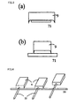
- bolster member (9) is placed on anode lead frame (71) such that burr (91) formed at the bottom side of bolster member (9) is not placed on the top surface of anode lead frame (71) as shown in Fig. 3(b) , in other words, burr (91) formed at the bottom side of bolster member (9) is positioned out of anode lead frame (71) as shown in Fig. 3(a) .
- a welding method may be resistance welding other than a method using a laser. More preferably, laser welding is used because welding of the chucked bolster member becomes mechanically simple.
- capacitor element (6) is connected to anode lead frame (71) having bolster member (9) joined thereto, and cathode lead frame (72).
- a connection method between bolster member (9) and capacitor element (6) is preferably laser welding.
- capacitor element (6) is coated with exterior resin (8) in the state that the bottom surface of anode lead frame (71) and the bottom surface of cathode lead frame (72) are bared.
- the solid electrolytic capacitor according to the present invention is manufactured.
Landscapes
- Engineering & Computer Science (AREA)
- Power Engineering (AREA)
- Microelectronics & Electronic Packaging (AREA)
- Fixed Capacitors And Capacitor Manufacturing Machines (AREA)
Abstract
Description
- The present invention relates to a solid electrolytic capacitor, and a method for manufacturing the same
-
Fig. 5 is a sectional view showing a conventional solid electrolytic capacitor (1). Solid electrolytic capacitor (1) includes a capacitor element (6), and an anode lead frame (71) and a cathode lead frame (72) each provided below capacitor element (6). Capacitor element (6) is coated with a synthetic resin (8). Capacitor element (6) has a structure that a dielectric oxide coating film (3), a cathode layer (4) and a cathode lead-out layer (5) are formed successively on a periphery of a valve metal sintered body (22). Herein, a valve metal denotes a metal having a dense and durable dielectric oxide coating film (3) formed by electrolytic oxidation treatment, and specific examples thereof include tantalum, niobium, aluminum, titanium and the like. - An anode lead (21) made of a valve metal protrudes from a center of sintered body (22) in a height direction. A bottom end surface of anode lead (21) is different in height from a top surface of anode lead frame (71). Therefore, a columnar bolster member (9) is interposed between anode lead (21) and anode lead frame (71) to establish an electrical connection between anode lead (21) and anode lead frame (71).
- As a method for forming bolster member (9), there has been known a method disclosed in Patent Document 1. According to this method, a tantalum wire is used for establishment of a connection between an anode lead and a lead frame in a solid electrolytic capacitor. There has been also known a method disclosed in
Patent Document 2. According to this method, as shown inFig. 4 , a plurality of capacitor elements (6) are attached to a carrier bar. In this state, a long nickel wire (10) enters respective anode leads (71), and then is connected to anode leads (71) by resistance welding. Thereafter, long nickel wire (10) is cut into an appropriate size. - Patent Document 1: Japanese Patent Laying-Open No.
2001-006977 - Patent Document 2: Japanese Patent Laying-Open No.
2005-244177 - In the foregoing methods, however, a bolster member is a columnar wire, and a contact area of the bolster member with a lead frame becomes small. Consequently, a strength of connection to the anode lead frame is weak. Further, a width of the bolster member in a direction perpendicular to a lead-out direction of an anode lead is smaller than a width of the anode lead frame. Herein, a burr is formed at a bottom side of the bolster member in a cutting process upon formation of the bolster member. For this reason, if the width of the bolster member is smaller than the width of the lead frame, as shown in
Fig. 3(b) , a clearance is created between bolster member (9) and anode lead frame (71), which results in deterioration of an adhesion property. Consequently, there arises a problem that a connection strength is deteriorated or a connection can not be established. - As shown in
Fig. 4 , the bolster members are formed simultaneously for the plurality of capacitor elements. Consequently, positional adjustment can not be performed for each bolster member, and positional accuracy with respect to an anode lead frame becomes incorrect. Thus, there arises a problem in alignment for laser welding. - The present invention has been devised to solve the foregoing problems. An object of the present invention is to provide a solid electrolytic capacitor with improved positional accuracy and adhesion property between an anode lead frame and a bolster member, and a method for manufacturing the same.
- The present invention provides a solid electrolytic capacitor including: a capacitor element in which a dielectric oxide coating film, a cathode layer made of a solid electrolyte and a cathode lead-out layer are formed successively on a periphery of an anode body from which an anode lead is led out; an anode lead frame which is connected to the anode lead via a bolster member; and a cathode lead frame which is connected to the cathode lead-out layer. Herein, the capacitor element is coated with an exterior resin in such a manner that the anode lead frame and the cathode lead frame are bared partially. A width of the bolster member in a direction perpendicular to a lead-out direction of the anode lead is larger than a width of the anode lead frame. The bolster member is provided inside the exterior resin without being bared.
- The present invention also provides a method for manufacturing a solid electrolytic capacitor, including the steps of: preparing a capacitor element in such a manner that a dielectric oxide coating film, a cathode layer made of a solid electrolyte and a cathode lead-out layer are formed successively on a periphery of an anode body from which an anode lead is led out; forming a bolster member; connecting the bolster member to an anode lead frame; connecting the anode lead to the bolster member; connecting a cathode lead frame to the cathode lead-out layer; coating the capacitor element with an exterior resin in a state that the anode lead frame and the cathode lead frame are bared partially; and dividing a frame to obtain a capacitor. Herein, in the step of forming the bolster member, a crossbar portion of a ladder-shaped frame is cut to form the bolster member. Moreover, the crossbar portion is chucked at a simultaneous timing with the cutting of the crossbar portion.
- More preferably, in the step of connecting the bolster member to the anode lead frame, the bolster member is pressed against the anode lead frame while being chucked, and then is welded to the anode lead frame.
- More preferably, the bolster member is connected to the anode lead frame by laser welding.
- According to the present invention, a bolster member is supplied in a form of a ladder-shaped frame, and only a crossbar portion is cut out as the bolster member. Therefore, the bolster member can be cut out from the ladder-shaped frame while being chucked. This improves usability and increases productivity.
- Further, a width of the bolster member in a direction perpendicular to a lead-out direction of an anode lead is larger than a width of a lead frame. Therefore, a burr which is formed at a bottom side of the bolster member in cutting of the bolster member is positioned out of a surface of the anode lead frame. Thus, the present invention ensures an adhesion property between the anode lead frame and the bolster member, increases a connection strength, and improves ESR characteristics.
- In addition, the bolster member is cut and, almost simultaneously, is connected to the anode lead frame while being chucked. Thus, the present invention allows positional adjustment, ensures positional accuracy between the bolster member and the lead frame more correctly, solves a problem in alignment for laser welding, and improves welding accuracy and welding strength.
- Hereinafter, description will be given of one embodiment of the present invention.
-
Fig. 1 is a sectional view showing a solid electrolytic capacitor according to one embodiment of the present invention. This solid electrolytic capacitor includes a capacitor element (6), and a bolster member (9) interposed between capacitor element (6) and an anode lead frame (71). Capacitor element (6) is coated with an exterior resin (8) in a state that a bottom surface of anode lead frame (71) and a bottom surface of a cathode lead frame (72) are bared. - The solid electrolytic capacitor is manufactured through the following steps. First, capacitor element (6) is prepared as follows. That is, a dielectric oxide coating film (3), a cathode layer (4) made of a solid electrolyte, and a cathode lead-out layer (5) made of silver paste or carbon are formed successively on a periphery of a valve function metal sintered body (22) from which an anode lead (21) is led out.
- Herein, a valve function metal denotes a metal having a dense and durable dielectric oxide coating film (3) formed by electrolytic oxidation treatment, and examples thereof include tantalum, niobium, aluminum, titanium and the like. Moreover, specific examples of the solid electrolyte include conductive polymers such as manganese dioxide, TCNQ (7,7,8,8-tetracyanoquinodimethane) complex salt, polypyrrole, polythiophene and polyaniline.
- Next, bolster member (9) is formed as follows. That is, a crossbar portion of a ladder-shaped frame (11) is cut as shown in
Fig. 6 . As shown inFig. 2(a) , more specifically, ladder-shaped frame (11) is cramped with an upper cutting die (121) and a lower cutting punch (122) in a vertical direction. As shown inFig. 2(b) , next, ladder-shaped frame (11) is cut in such a manner that lower cutting punch (122) moves upward. - Simultaneously with the formation of bolster member (9), bolster member (9) is chucked by a vertically movable chuck (13). Herein, a width of the punch for forming bolster member (9) is larger than a width of anode lead frame (71). Moreover, an initial position of chuck (13) may be spaced away from ladder-shaped frame (11) or may come into contact with ladder-shaped frame (11). Alternatively, bolster member (9) may be formed in such a manner that upper cutting die (121) moves downward. As described above, only the crossbar portion corresponding to the bolster member is cut out from the ladder-shaped frame. This improves usability and increases productivity.
- Upon formation of bolster member (9), further, there is a minute clearance between upper cutting die (121) and lower cutting punch (122), which forms a burr (91) at a bottom side of bolster member (9).
- Next, bolster member (9) is connected to anode lead frame (71) as follows. First, bolster member (9) obtained by the cutting is aligned with anode lead frame (71) and is placed on a top surface of anode lead frame (71) while being chucked. Then, a laser is applied to bolster member (9) and anode lead frame (71).
- Herein, bolster member (9) is placed on anode lead frame (71) such that burr (91) formed at the bottom side of bolster member (9) is not placed on the top surface of anode lead frame (71) as shown in
Fig. 3(b) , in other words, burr (91) formed at the bottom side of bolster member (9) is positioned out of anode lead frame (71) as shown inFig. 3(a) . A welding method may be resistance welding other than a method using a laser. More preferably, laser welding is used because welding of the chucked bolster member becomes mechanically simple. - Next, capacitor element (6) is connected to anode lead frame (71) having bolster member (9) joined thereto, and cathode lead frame (72). A connection method between bolster member (9) and capacitor element (6) is preferably laser welding. Thereafter, capacitor element (6) is coated with exterior resin (8) in the state that the bottom surface of anode lead frame (71) and the bottom surface of cathode lead frame (72) are bared. Thus, the solid electrolytic capacitor according to the present invention is manufactured.
- Each bolster member is connected to the cathode lead frame through the foregoing steps. Therefore, the present invention facilitates the alignment of the bolster member and improves the positional accuracy. In addition, the burr formed at the bottom side of the bolster member is positioned out of the lead frame. Therefore, the present invention can provide a solid electrolytic capacitor with improved joining strength and joining reliability between a bolster member and an anode lead frame.
-
-
Fig. 1 is a sectional view showing a solid electrolytic capacitor according to the present invention. -
Fig. 2 each shows a method for forming a bolster member according to the present invention. -
Fig. 3(a) shows a state that the bolster member according to the present invention is joined to a lead frame, andFig. 3(b) shows a state that a conventional bolster member is joined to a lead frame. -
Fig. 4 shows a method for forming the conventional bolster member. -
Fig. 5 is a sectional view showing a conventional solid state electrolytic capacitor. -
Fig. 6 shows a ladder-shaped frame for use in the present invention. -
- 1
- Conventional solid electrolytic capacitor
- 2
- Anode body
- 21
- Sintered body
- 22
- Anode lead
- 3
- Dielectric oxide coating film
- 4
- Cathode layer
- 5
- Cathode lead-out layer
- 6
- Capacitor element
- 71
- Anode lead frame
- 72
- Cathode lead frame
- 8
- Exterior resin
- 9
- Bolster member
- 91
- Burr
- 10
- Nickel wire
- 11
- Ladder-shaped frame
- 121
- Upper cutting die
- 122
- Lower cutting punch
- 13
- Vertically movable chuck
Claims (5)
- A solid electrolytic capacitor comprising:a capacitor element in which a dielectric oxide coating film, a cathode layer made of a solid electrolyte and a cathode lead-out layer are formed successively on a periphery of an anode body from which an anode lead is led out;an anode lead frame which is connected to said anode lead via a bolster member; anda cathode lead frame which is connected to said cathode lead-out layer, whereinsaid capacitor element is coated with an exterior resin in such a manner that said anode lead frame and said cathode lead frame are bared partially,a width of said bolster member in a direction perpendicular to a lead-out direction of said anode lead is larger than a width of said anode lead frame, andsaid bolster member is provided inside the exterior resin without being bared.
- A method for manufacturing a solid electrolytic capacitor, comprising the steps of:preparing a capacitor element in such a manner that a dielectric oxide coating film, a cathode layer made of a solid electrolyte and a cathode lead-out layer are formed successively on a periphery of an anode body from which an anode lead is led out;forming a bolster member;connecting said bolster member to an anode lead frame;connecting said anode lead to said bolster member;connecting a cathode lead frame to said cathode lead-out layer;coating said capacitor element with an exterior resin in a state that said anode lead frame and said cathode lead frame are bared partially; anddividing a frame to obtain a capacitor, whereinin the step of forming said bolster member, a crossbar portion of a ladder-shaped frame is cut to form said bolster member.
- The method according to claim 2, wherein
in the step of forming said bolster member, the crossbar portion of the ladder-shaped frame is chucked at a substantially simultaneous timing with the cutting of the crossbar portion. - The method according to claim 2, wherein
in the step of connecting said bolster member to said anode lead frame, the bolster member is pressed against the anode lead frame while being chucked, and then is welded to the anode lead frame. - The method according to claims 2 to 4, wherein
said bolster member is connected to said anode lead frame by laser welding.
Applications Claiming Priority (2)
| Application Number | Priority Date | Filing Date | Title |
|---|---|---|---|
| JP2006273214A JP4836738B2 (en) | 2006-10-04 | 2006-10-04 | Manufacturing method of solid electrolytic capacitor |
| PCT/JP2007/062632 WO2008041397A1 (en) | 2006-10-04 | 2007-06-22 | Solid electrolytic capacitor and its manufacturing method |
Publications (2)
| Publication Number | Publication Date |
|---|---|
| EP2071599A1 true EP2071599A1 (en) | 2009-06-17 |
| EP2071599A4 EP2071599A4 (en) | 2011-09-07 |
Family
ID=39268262
Family Applications (1)
| Application Number | Title | Priority Date | Filing Date |
|---|---|---|---|
| EP07767441A Withdrawn EP2071599A4 (en) | 2006-10-04 | 2007-06-22 | Solid electrolytic capacitor and its manufacturing method |
Country Status (7)
| Country | Link |
|---|---|
| US (1) | US8072735B2 (en) |
| EP (1) | EP2071599A4 (en) |
| JP (1) | JP4836738B2 (en) |
| KR (1) | KR101045715B1 (en) |
| CN (2) | CN102122575B (en) |
| TW (1) | TWI344660B (en) |
| WO (1) | WO2008041397A1 (en) |
Families Citing this family (14)
| Publication number | Priority date | Publication date | Assignee | Title |
|---|---|---|---|---|
| JP5216423B2 (en) * | 2008-06-05 | 2013-06-19 | 三洋電機株式会社 | Manufacturing method of solid electrolytic capacitor |
| JP5474441B2 (en) * | 2009-08-06 | 2014-04-16 | 三洋電機株式会社 | Solid electrolytic capacitor and manufacturing method thereof |
| JP2011049347A (en) | 2009-08-27 | 2011-03-10 | Sanyo Electric Co Ltd | Solid electrolytic capacitor and method of manufacturing the same |
| JP2011238738A (en) | 2010-05-10 | 2011-11-24 | Sanyo Electric Co Ltd | Solid electrolytic capacitor and manufacturing method of the same |
| JP5796194B2 (en) | 2010-12-13 | 2015-10-21 | パナソニックIpマネジメント株式会社 | Solid electrolytic capacitor |
| JP5796193B2 (en) | 2010-12-13 | 2015-10-21 | パナソニックIpマネジメント株式会社 | Solid electrolytic capacitor |
| JP5796195B2 (en) | 2011-01-12 | 2015-10-21 | パナソニックIpマネジメント株式会社 | Solid electrolytic capacitor |
| JP6186584B2 (en) | 2011-11-25 | 2017-08-30 | パナソニックIpマネジメント株式会社 | Solid electrolytic capacitor and manufacturing method thereof |
| WO2014157425A1 (en) * | 2013-03-28 | 2014-10-02 | 日本ケミコン株式会社 | Electrolytic capacitor and method for manufacturing same |
| CN103713791A (en) * | 2013-12-11 | 2014-04-09 | 深圳市奥科立盛科技有限公司 | Capacitive-type touch module with single plastic sheet, production method for same, and OPS touch screen |
| KR102078008B1 (en) * | 2014-02-13 | 2020-02-17 | 삼성전기주식회사 | Solid electrolytic capacitor, manufacturing of the same and chip-type electronic part |
| CN103786033B (en) * | 2014-02-18 | 2016-05-11 | 南通新三能电子有限公司 | A kind of electrolytic capacitor laser soldering device and method of work thereof |
| CN107895649A (en) * | 2017-12-15 | 2018-04-10 | 株洲中电电容器有限公司 | It is a kind of to mount solid tantalum capacitor without leadframe surfaces |
| JP7215860B2 (en) * | 2018-09-26 | 2023-01-31 | キョーセラ・エイブイエックス・コンポーネンツ・コーポレーション | Solid electrolytic capacitor and manufacturing method thereof |
Family Cites Families (14)
| Publication number | Priority date | Publication date | Assignee | Title |
|---|---|---|---|---|
| US4488204A (en) * | 1983-11-01 | 1984-12-11 | Union Carbide Corporation | Device for use in making encapsulated chip capacitor assemblies |
| JP2501668Y2 (en) | 1989-05-29 | 1996-06-19 | 日本電気株式会社 | Surface mount electrical components |
| JP3312246B2 (en) | 1999-06-18 | 2002-08-05 | 松尾電機株式会社 | Manufacturing method of chip capacitor |
| JP3349133B2 (en) * | 2000-04-07 | 2002-11-20 | エヌイーシートーキン株式会社 | Chip type capacitor, method of manufacturing the same, and mold |
| US6625009B2 (en) * | 2001-04-05 | 2003-09-23 | Rohm Co., Ltd. | Solid electrolytic capacitor and method of making the same |
| JP2002367862A (en) * | 2001-04-05 | 2002-12-20 | Rohm Co Ltd | Solid electrolytic capacitor and method of manufacturing the same |
| JP2004228424A (en) * | 2003-01-24 | 2004-08-12 | Nec Tokin Corp | Chip electrolytic capacitor and method of manufacturing the same |
| JP2004253615A (en) * | 2003-02-20 | 2004-09-09 | Nec Tokin Corp | Solid electrolytic capacitor and manufacturing method thereof |
| US6995972B2 (en) * | 2004-01-28 | 2006-02-07 | Sanyo Electric Co., Ltd. | Solid electrolytic capacitor and method for manufacturing the same |
| JP2005244177A (en) | 2004-01-28 | 2005-09-08 | Sanyo Electric Co Ltd | Solid electrolytic capacitor and its manufacturing method |
| WO2005083729A1 (en) | 2004-02-27 | 2005-09-09 | Rohm Co., Ltd. | Solid electrolytic capacitor |
| JP4583132B2 (en) * | 2004-10-08 | 2010-11-17 | 三洋電機株式会社 | Solid electrolytic capacitor |
| JP2006190965A (en) * | 2004-12-10 | 2006-07-20 | Nec Tokin Corp | Solid electrolytic capacitor with bottom-surface terminals, manufacturing method therefor, and lead frame for use therein |
| JP2006286939A (en) * | 2005-03-31 | 2006-10-19 | Sanyo Electric Co Ltd | Solid-state electrolytic capacitor and method of manufacturing the same |
-
2006
- 2006-10-04 JP JP2006273214A patent/JP4836738B2/en not_active Expired - Fee Related
-
2007
- 2007-06-22 KR KR1020077025864A patent/KR101045715B1/en not_active Expired - Fee Related
- 2007-06-22 CN CN201010583725XA patent/CN102122575B/en not_active Expired - Fee Related
- 2007-06-22 US US12/443,572 patent/US8072735B2/en not_active Expired - Fee Related
- 2007-06-22 CN CN200780000522XA patent/CN101322204B/en not_active Expired - Fee Related
- 2007-06-22 EP EP07767441A patent/EP2071599A4/en not_active Withdrawn
- 2007-06-22 WO PCT/JP2007/062632 patent/WO2008041397A1/en not_active Ceased
- 2007-08-21 TW TW096130827A patent/TWI344660B/en not_active IP Right Cessation
Also Published As
| Publication number | Publication date |
|---|---|
| CN102122575A (en) | 2011-07-13 |
| KR20090017959A (en) | 2009-02-19 |
| JP4836738B2 (en) | 2011-12-14 |
| US8072735B2 (en) | 2011-12-06 |
| KR101045715B1 (en) | 2011-06-30 |
| CN101322204B (en) | 2011-06-01 |
| EP2071599A4 (en) | 2011-09-07 |
| US20100271756A1 (en) | 2010-10-28 |
| TWI344660B (en) | 2011-07-01 |
| TW200818225A (en) | 2008-04-16 |
| JP2008091784A (en) | 2008-04-17 |
| CN102122575B (en) | 2013-02-27 |
| WO2008041397A1 (en) | 2008-04-10 |
| CN101322204A (en) | 2008-12-10 |
Similar Documents
| Publication | Publication Date | Title |
|---|---|---|
| US8072735B2 (en) | Solid electrolytic capacitor, and method for manufacturing the same | |
| US7135754B2 (en) | Chip type solid electrolytic capacitor having a small size and a simple structure | |
| JP5132374B2 (en) | Solid electrolytic capacitor and manufacturing method thereof | |
| JP2008283224A (en) | Solid electrolytic capacitor | |
| US8325466B2 (en) | Solid electrolytic capacitor with bent terminal and method of manufacturing same | |
| US8614880B2 (en) | Solid electrolytic capacitor including positive and negative electrode lead terminals | |
| US8344735B2 (en) | Solid electrolytic capacitor | |
| US8562695B2 (en) | Solid electrolytic capacitor and a method for manufacturing the same | |
| US10665394B2 (en) | Solid electrolytic condenser and method of manufacturing the same | |
| US20060012946A1 (en) | Solid electrolytic capacitor and method for manufacturing the same | |
| JP4653682B2 (en) | Chip-shaped solid electrolytic capacitor | |
| JP4767275B2 (en) | Solid electrolytic capacitor | |
| US8570712B2 (en) | Solid electrolytic capacitor | |
| JP2012004342A (en) | Solid electrolytic capacitor and method of manufacturing the same | |
| JP5341149B2 (en) | Solid electrolytic capacitor | |
| US8503166B2 (en) | Solid electrolytic capacitor | |
| JP2007201122A (en) | Solid electrolytic capacitor and manufacturing method thereof | |
| JP2006032746A (en) | Solid electrolytic capacitor | |
| JP2005039043A (en) | Chip electrolytic capacitor | |
| JP2012033603A (en) | Solid electrolytic capacitor | |
| US8659877B2 (en) | Solid electrolytic capacitor | |
| JP2007287723A (en) | Multilayer capacitor | |
| JP2012033602A (en) | Capacitor element and manufacturing method thereof and solid electrolytic capacitor manufacturing method | |
| JP2004349724A (en) | Chip-like solid electrolytic capacitor |
Legal Events
| Date | Code | Title | Description |
|---|---|---|---|
| PUAI | Public reference made under article 153(3) epc to a published international application that has entered the european phase |
Free format text: ORIGINAL CODE: 0009012 |
|
| 17P | Request for examination filed |
Effective date: 20090331 |
|
| AK | Designated contracting states |
Kind code of ref document: A1 Designated state(s): AT BE BG CH CY CZ DE DK EE ES FI FR GB GR HU IE IS IT LI LT LU LV MC MT NL PL PT RO SE SI SK TR |
|
| AX | Request for extension of the european patent |
Extension state: AL BA HR MK RS |
|
| RIN1 | Information on inventor provided before grant (corrected) |
Inventor name: IHARA, HAYATOSHI Inventor name: HIRAMATSU, KATSUMI Inventor name: KASAHARA, TAKESHI Inventor name: TAKAHASHI, YUSUKE Inventor name: FUJII, EIZO |
|
| DAX | Request for extension of the european patent (deleted) | ||
| RBV | Designated contracting states (corrected) |
Designated state(s): DE FR GB |
|
| A4 | Supplementary search report drawn up and despatched |
Effective date: 20110804 |
|
| RIC1 | Information provided on ipc code assigned before grant |
Ipc: H01G 9/00 20060101ALI20110729BHEP Ipc: H01G 9/012 20060101AFI20110729BHEP |
|
| RAP1 | Party data changed (applicant data changed or rights of an application transferred) |
Owner name: PANASONIC INTELLECTUAL PROPERTY MANAGEMENT CO., LT |
|
| STAA | Information on the status of an ep patent application or granted ep patent |
Free format text: STATUS: THE APPLICATION HAS BEEN WITHDRAWN |
|
| RIC1 | Information provided on ipc code assigned before grant |
Ipc: H01G 9/012 20060101AFI20180207BHEP Ipc: H01G 9/15 20060101ALI20180207BHEP |
|
| 18W | Application withdrawn |
Effective date: 20180209 |