EP2071073A1 - Stranding machine with a lubricating device - Google Patents
Stranding machine with a lubricating device Download PDFInfo
- Publication number
- EP2071073A1 EP2071073A1 EP07122970A EP07122970A EP2071073A1 EP 2071073 A1 EP2071073 A1 EP 2071073A1 EP 07122970 A EP07122970 A EP 07122970A EP 07122970 A EP07122970 A EP 07122970A EP 2071073 A1 EP2071073 A1 EP 2071073A1
- Authority
- EP
- European Patent Office
- Prior art keywords
- lubricant
- stranding machine
- machine according
- distributor
- stranding
- Prior art date
- Legal status (The legal status is an assumption and is not a legal conclusion. Google has not performed a legal analysis and makes no representation as to the accuracy of the status listed.)
- Withdrawn
Links
Images


Classifications
-
- D—TEXTILES; PAPER
- D07—ROPES; CABLES OTHER THAN ELECTRIC
- D07B—ROPES OR CABLES IN GENERAL
- D07B7/00—Details of, or auxiliary devices incorporated in, rope- or cable-making machines; Auxiliary apparatus associated with such machines
- D07B7/02—Machine details; Auxiliary devices
- D07B7/12—Machine details; Auxiliary devices for softening, lubricating or impregnating ropes, cables, or component strands thereof
Definitions
- the invention relates to a stranding machine with a lubricating device for wire or synthetic fiber ropes. Specifically, the invention relates to the field of stranding machines for the production of suspension systems for elevator systems.
- a fast-running basket twisting machine in particular a Schnellverseilmaschine known with a lubricating device.
- the from the DE 1 206 332 known embodiment of a stranding machine is based on the idea that in fast-running stranding the peripheral outer wires or outer strands form an impenetrable baffle, which ejects an externally applied lubricant due to the centrifugal force again.
- the lubricating device is therefore designed so that the lubricant is not applied from the outside to the rotating Aderkegel, but from the inside in the immediate vicinity of the stranding point. Since there are low centrifugal forces act, the distance between the wires is tight and the stranding follows immediately, the introduced, excess lubricant is pressed only by the merging of the wires to the outside, the interior between the wires remains fully filled with grease.
- the from the DE 1 206 332 known stranding machine has the disadvantage that the application of the lubricant takes place only at certain points in the interior, wherein the distribution of the lubricant takes place only by the stranding.
- the distribution of the lubricant in the rope can thereby hardly be affected, which may result in an unequal distribution of the lubricant in the rope.
- the known stranding machine is only suitable for relatively viscous lubricants, since the distribution of the lubricant takes place only by pressing out of the lubricant from the inside of the rope to the outside during the stranding.
- the field of application of the known stranding machine is therefore limited.
- the stranding machine according to the invention with the features of claim 1 has the advantage that an application of the lubricant is improved during the stranding.
- the lubricant can be applied more targeted and thus better distributed over the strands.
- the lubricant device rotates together with the rotatable distributor disc.
- the lubricant device may, inter alia, have a lubricant pump and a piston pressure accumulator connected to the lubricant pump.
- the lubricant pump can then remove lubricant from the Promote piston accumulator to the distributor disc.
- Both the lubricant pump and the piston accumulator then rotate together with the distributor disc.
- An advantageous possibility, in order to drive the lubricant pump is that the lubricant pump is driven by a non-rotating and thus stationary ring gear on a revolving Satelitenritzel.
- the satellite sprocket runs along the stationary gear ring, so that energy is supplied as a function of the rotational speed of the lubricant pump.
- the lubricant pump can be set so that the flow rate depends approximately linearly on the rotational speed. It is further advantageous that between the satellite gear and the lubricant pump, a continuously variable, adjustable transmission is provided to adjust the desired flow rate for a certain speed.
- the piston accumulator which can rotate as part of the lubricant device with the distributor disc, provides a wet lubricant, which is guided to the distributor disc. Due to the rotation of the piston accumulator, the position of the piston accumulator constantly changes with respect to gravity. Further act on the lubricant in the piston pressure accumulator by the rotation in addition to gravity further forces.
- the piston accumulator has a piston which is displaceably mounted, so that the wet lubricant provided in the piston accumulator fills as completely as possible a partial space delimited by the displaceable piston. This is an at least largely bubble-free promotion of lubricant from the Piston accumulator allows the lubricant pump.
- a plurality of connection points are provided on the distributor plate, where the distributor disc can be connected via lubricant lines to the lubricant device.
- the guide passages in the distributor disc are associated with the connection points, wherein a connection point is connected to one or more guide passages.
- each guide passage is associated with only one connection point, but from a connection point, the connection with a plurality of guide passages may be possible. That is, by connecting the lubricant device via a lubricant line to the connection point, a specific part of the guide passages in the distributor plate can be selectively supplied with lubricant.
- the connection points which are connected via lubricant lines to the lubricant device, it is therefore possible to specify in a targeted manner in which guide passages lubricant is applied to the respective continuous strand.
- the amount applied to a strand per unit time in the region of a guide passage can advantageously be influenced via the configuration of the lubricant line, in particular the throttle resistance of the lubricant line. It is also possible that connection points remain free, although strands are guided by the associated guide passages. As a result, a lubricant application can be targeted to only a part of the strands of the rope to be produced.
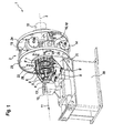
- Fig. 1 shows a stranding machine 1 with a lubricant device 2 in a three-dimensional representation.
- the stranding machine 1 can serve in particular as a stranding machine for suspension means of elevator installations.
- suspension means are especially wire or synthetic fiber ropes to understand.
- the stranding machine 1 ensures the order of at least one lubricant from the lubricant device 2 on strands of the rope to be produced, in particular suspension means.
- the term strand is to be understood generally.
- a strand may already consist of a plurality of strands, in particular stranded wires, as a result of previous stranding.
- the rope which is produced by the stranding machine 1 of a plurality of strands, in turn serve as a strand for a subsequent stranding.
- a rope made by the stranding machine 1 can also be further treated in other ways.
- the lubricant device 2 of the stranding machine 1 is particularly suitable for the introduction of wet lubricants in the manufactured rope.
- the stranding machine 1 according to the invention is also suitable for other applications.
- the stranding machine 1 enables a defined application of a lubricant, in particular of wet lubricants, to the strands during the stranding process.
- Lifting means of elevators are basically limited in their lifetime.
- the life of suspension elements can be significantly increased, so that the cost of rope changes are reduced.
- the coefficient of friction between the friction partners, in particular from strand to strand and rope to disc, and thus also the occurring Wear can be reduced, which is caused by the rollover of the rope via a traction sheave, a pulley or the like.
- the application of the lubricant to the strands takes place in the stranding machine 1 during the stranding, so that an additional production step, in which lubricant is applied to the manufactured rope, can be omitted.
- the stranding machine 1 has distributor disks 4, 5, 6, 7.
- the distributor disks 4, 5 are of particular relevance, since they are connected to the lubricant device 2 via a plurality of lubricant lines 8, 8 ', 9, 9'.
- lubricant lines 8, 8 ', 9, 9' There are in the Fig. 1 for simplicity of illustration only the lubricant lines 8, 8 ', 9, 9', which are connected to the distributor plate 4, characterized.
- the lubricant device 2 rotates together with the distributor disks 4, 5, 6, 7 and the lubricant lines 8, 8 ', 9, 9' about the rotation axis 3. For example, a speed of about 55 revolutions per minute can be specified.
- the drive can be done via a central shaft 10.
- the strands are guided in a direction 11 approximately along the axis of rotation 3 through the distributor disks 4, 5, 6, 7.
- the distributor disks 4, 5, 6, 7 guide passages, wherein a guide passage 12 in the distributor disk 4 in the Fig. 3 is shown in more detail.
- a stranding point is predetermined, at which the strands guided by the distributor disks 4, 5, 6, 7 converge from different directions. The radial distance Therefore, the guide passage 12 to the rotation axis 3 tends to decrease in the direction 11.
- the radial distance of the guide passages in the distributor disc 5, which is located farther from the stranding point than the distributor disc 4, may also be smaller than the radial distance of the guide passages 12 in the distributor disc 4.
- the distributor discs 4, 5 are arranged very close to the stranding point and the guided through the distributor disc 5 strands, so to speak, form the core of the rope, while the guided through the distributor disc 4 strands form the shell of the rope.
- Such an arrangement with guide passages 12 arranged relatively close to the axis of rotation 3 has the advantage that after the application of the lubricant, the rotational forces are relatively low, so that a centrifuging of the lubricant applied to the strands is prevented or at least reduced.
- the lubricant device 2 two piston pressure accumulators 14, 15 and lubricant pumps 16, 17, wherein at the Fig. 1 the lubricant pump 17 is covered.
- the piston accumulator 14 is connected to the lubricant pump 16 in a suitable manner.
- the piston accumulator 15 is connected to the lubricant pump 17.
- the configuration of the piston pressure accumulator 14, 15 is in the Fig. 5 described in detail with reference to the Kolbendtikiquess 15.
- the lubricant pumps 16, 17 convey a lubricant contained in the piston pressure accumulators 14, 15, in particular a wet lubricant, via the lubricant lines 8, 8 ', 9, 9' to the distributor disks 4, 5 Lubricant lines may be provided.
- individual lubricant lines can also be omitted or a blocking option can be provided for each of the lubricant lines.
- the lubricant pump 16 may be put out of operation, so that lubricant is guided to the distributor disks 4, 5 only via the lubricant lines 8, 9 connected to the lubricant pump 17.
- the stranding machine 1 has a stationary positioning table 20.
- the cable guide 13 is slidably mounted in the direction of the axis of rotation 13.
- a toothed ring 22 is connected to the setting table 20 by means of a sprocket holder 21.
- the toothed ring 22 thus stands still, that is does not rotate with the lubricant device 2.
- the lubricant device 2 is arranged between turntables 23, 24, wherein the elements of the lubricant device 2, in particular the piston pressure accumulators 14, 15 and the lubricant pumps 16, 17, in a suitable manner are connected to the hubs 23, 24.
- the hubs 23, 24 thereby form a unit with the lubricant device 2, which rotates together in operation about the rotation axis 3.
- Satelitenritzel 25, 26 are rotatably mounted, wherein the storage in each case in an integrated into the lubricant pump 16 gear 16 ', 17' takes place.
- the satellite gears 25, 26 are arranged opposite to the rotational axis 23 with respect to the axis of rotation. Further, the satellite pinion gears 25, 26 are engaged with the ring gear 22 on opposite sides.
- the center shaft 10 is driven, and thus the rotary disk 23 also rotates, the satellite pinion gears 25, 26 run on the ring gear 22 along, so that the Satelitenritzel 25, 26 are driven by means of the toothed ring 22.
- the mechanical energy available via the central shaft 10 can be partially utilized to operate the lubricant pumps 16, 17 by means of the sprocket 22 and satellite sprockets 25, 26.
- the gear 16 ', 17' are designed as stepless, variable transmission 16 ', 17', so that for a certain speed, for example, 50 revolutions per minute, a certain flow rate of lubricant to the distributor disks 4, 5 can be adjusted.
- the delivery rate is at least substantially proportional to the instantaneous rotational speed of the stranding machine 1 and thus to the cable transport taking place in the direction 11.
- at least approximately a uniform lubricant entry into the cable is made possible, which is independent of the rotational speed of the stranding machine 1.
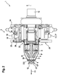
- Fig. 2 shows an excerpt, axial section through in the Fig. 1 shown stranding machine 1 according to the embodiment of the invention.
- a disk-shaped part 13 'of the cable guide 13 is also shown, which defines the position of the stranding point 13 ", whereby the arrangement of the disk-shaped part 13' of the cable guide 13 relative to the stranding machine 1 is chosen such that a reliable implementation of the stranding process and thus a production of a properly stranded rope is possible.
- the table 20 and the sprocket holder 21 are for Simplification of the illustration not shown. Furthermore, the toothed ring 22 is concealed in the illustration essentially by the turntable 23. From the Fig. 2 is a possible construction can be seen to connect the lubricant device 2 with the central shaft 10 so that a reliable rotation of all components about the rotation axis 3 is possible without limiting the operation. Furthermore, a reliable function of the lubricant delivery to the strands by the interaction of the individual components of the lubricant device 2, in particular the piston pressure accumulator 14, 15, the lubricant pumps 16 and 17 and the gear 16 ', 17', and the lubricant lines 8, 8 ', 9 , 9 'allows.
- the lubricant lines 8, 8 ', 9, 9' lead the lubricant in the distributor disks 4, 5, as it is based on the 3 and 4 is described in further detail.
- the distributor disks 4, 5 have connection points 30, 31, of which in the Fig. 2 only the connection points 30, 31 are marked. At the connection points 30, 31, the lubricant lines 8 ', 9' are connected to the distributor disc 4 in this case. But it is also possible that one or more connection points 30, 31 remain free or that the supply of lubricant by blocking one or more lubricant lines 8 ', 9' to the connection points 30, 31 is interrupted. For example, the connection point 30 remain free or the lubricant line 8 'are locked, in both cases the guide passage 12 in the distributor plate 4, which is assigned to the connection point 30, remains dry and thus no lubricant transfer to the guided through the guide passage 12 strand.
- a lubricant line 8 'connected to the manifold 4, which conveys lubricant via the connection point 30 to the guide passage 12 the extent of the lubricant delivery and thus the amount of lubricant per unit time can be specifically influenced.
- the influence is possible by adjusting the throttle effect of the lubricant line 8 '.
- the lubricant line 8 ' optionally be replaced by a longer lubricant line or by a lubricant line with at least partially reduced diameter to reduce the conveyed to the guide passage 12 amount of lubricant per unit time. It should be noted that in this way, in particular a relative change in the intended amount of lubricant amount is possible.
- the amount of lubricant delivered via the lubricant line 8 ' can be influenced relative to the quantity of lubricant delivered via the lubricant line 9'.
- a plurality of guide passages 12 in a distributor disc may be connected to a single connection point, for example the connection point 30.
- each of these leading passages 12 is reaching Quantity of lubricant per unit time at least substantially the same size.
- lubricant lines 8, 8 ', 9, 9' can be saved. The targeted influencing of the delivered to the individual strands amount of lubricant can then be done by replacing the distributor plate 4 against a differently designed distribution disc.
- the stranding machine 1 allows a targeted influencing the delivered to a strand per unit time or per unit length of lubricant, the total amount of lubricant dispensed at least substantially linearly proportional to the number of revolutions of the central shaft 10. Since the rope feed in the direction 11, that is, the amount of rope produced in meters, depends substantially linearly proportional to the number of revolutions of the central shaft 10, thus the length of lubricant introduced into the rope per length unit for a given setting of the stranding machine 1 is substantially constant.
- a support means in particular a wire or synthetic fiber rope
- an optimized distribution of the lubricant can be specified within the suspension element.
- a support of high quality can be produced.
- Fig. 3 shows the in Fig. 2 With III designated section of the distributor plate 4 in an excerpted sectional view.
- the lubricant line 8 ' is connected to the connection point 30 of the distributor disk 4.
- the lubricant line 8 ' is connected in a suitable manner with the distributor disk 4. Further, a strand 32 is guided by the guide passage 12 in the distributor disc 4, which runs in the direction 11 'through the distributor disc 4.
- the directional arrow 11 ' shows at least substantially on the axis of rotation 3 or on the stranding point 13 "(FIG. Fig. 2 ).
- the distributor disc 4 has an internal recess 30, which is designed as a channel in this embodiment.
- lubricant in particular a wet lubricant
- the recess 33 has a cylindrical lubricating region 35, which is designed so that the lubricant passes from all sides to the strand 32. Since the strand 32 slides in the direction 11 'through the guide passage 12, lubricant is continuously transferred from the lubrication region 35 to the strand 32.
- the distributor disc 4 has a side 36 facing away from the stranding point 13 "and a side 37 facing the stranding point 13".
- the strand 32 has a lateral surface 38.
- the lateral surface 38 of the strand 32 is still unwetted. After passing through the distributor disc 4, the lateral surface 38 is wetted with the lubricant.
- the lateral surface 38 is provided on the side 37 of the distributor disc 4 with lubricant. Since the guide passage 12 is arranged relatively close to the rotational axis 3, the forces acting on the lubricant on the lateral surface 38 forces are relatively low, so that an undesirable centrifuging of the lubricant prevented or at least quantitatively is reduced. Since the distance of the distributor disk 4 to the stranding point 13 "is also relatively short, the lubricant applied to the lateral surface 38 at least largely reaches the suspension element.
- Fig. 4 shows a partial cut through in the Fig. 3 shown distributor disk along the section line designated IV.
- the lubricant designed as a wet lubricant flows in the flow direction 34 through the inner recess 33 to the lubrication region 35 of the recess 33, through which the strand 32 is guided. It is illustrated by the other flow arrows, as the lubricant passes from all sides to the strand 32.
- the cylindrical configuration of the lubricating region 35 allows a relatively uniform wetting of the lateral surface 38 of the strand 32.
- the guide passage 12 is thus configured in the form of a nozzle, through which the strand 32 is guided.
- the lubricating region 35 can also be designed differently.
- the lubricant can be selectively applied to a part of the lateral surface 38, in particular a radially inner part of the lateral surface 38.
- the inner recess 33 may also be configured so that more guide passages in the distributor plate 4 are supplied with the lubricant.
- Fig. 5 shows the piston pressure accumulator 15 of the lubricant device 2 of the embodiment of the invention in an axial sectional view.
- the piston pressure accumulator 14 is in accordance with the Piston pressure accumulator 15 designed.
- the piston accumulator 15 has an axis 40, wherein the orientation of the axis 40 in the operation of the stranding machine 1 is constantly changing, so that the angle between the axis 40 and the direction of gravity always changes. Further, the piston accumulator 15 is exposed to the forces occurring during the rotation.
- the piston pressure accumulator 15 has an interior space 41, which is divided by a displaceably arranged piston 44 into parts 42, 43. In this case, the part 42 of the inner space 41 serves to receive lubricant, in particular a wet lubricant.
- the piston pressure accumulator 15 has a compressed air connection 45, to which a compressed air accumulator is connected during operation of the stranding machine 1. Via the compressed air connection 45, the part 43 of the inner space 41 is filled with compressed air, wherein the piston 44 is acted upon in the direction of the part 42 of the inner space 41, in which the lubricant is located. As a result, it is achieved that the size of the part 42 of the inner space 41 continuously adapts to the amount of lubricant decreasing in operation in the piston pressure accumulator 15, whereby the formation of bubbles or the like in the lubricant is prevented or at least reduced. The removal of the lubricant via the lockable output 46 which is connected in a suitable manner with the lubricant pump 17.
- a magnetic ring 47 is provided on the piston 44. Further, in the region of the output 46, a sensor 48 is arranged, which is designed as a magnetic sensor 48.
- the piston 44 comes close to a cover inside 49 of a lid 50 of the piston accumulator 15. With the piston 44 also reaches the magnetic ring 47 in the vicinity of the inner lid side 49 of the lid 50.
- the sensor 48 can detect in time that the piston 44 is disposed at or near the lid inner side 49.
- the speed of the stranding machine 1 can then be reduced and the stranding machine 1 stopped. Due to the advantageous embodiment of the stranding machine 1, the lubricant introduction into the rope during the reduction of the speed and the stopping of the stranding machine 1 is continued evenly. After filling the piston pressure accumulator 14, 15 with additional lubricant, the stranding machine 1 can be started again and the speed of the stranding machine 1 can be increased to the desired speed. Here, evenly lubricant is introduced into the rope. Thus, even with the occurrence of interruptions, for example, to fill the piston accumulator 14, 15, consistently a consistent quality of the rope can be ensured.
Abstract
Description
Die Erfindung betrifft eine Verseilmaschine mit einer Schmiereinrichtung für Draht- oder Kunstfaserseile. Speziell betrifft die Erfindung das Gebiet der Verseilmaschinen zur Herstellung von Tragmitteln für Aufzuganlagen.The invention relates to a stranding machine with a lubricating device for wire or synthetic fiber ropes. Specifically, the invention relates to the field of stranding machines for the production of suspension systems for elevator systems.
Aus der
Die aus der
Die erfindungsgemäße Verseilmaschine mit den Merkmalen des Anspruchs 1 hat den Vorteil, dass eine Aufbringung des Schmiermittels während der Verseilung verbessert ist. Insbesondere kann das Schmiermittel gezielter aufgebracht und somit besser über die Litzen verteilt werden.The stranding machine according to the invention with the features of claim 1 has the advantage that an application of the lubricant is improved during the stranding. In particular, the lubricant can be applied more targeted and thus better distributed over the strands.
Durch die in den Unteransprüchen aufgeführten Maßnahmen sind vorteilhafte Weiterbildungen der im Anspruch 1 angegebenen Verseilmaschine möglich.The measures listed in the dependent claims advantageous developments of the stranding machine specified in claim 1 are possible.
In vorteilhafter Weise rotiert die Schmiermitteleinrichtung zusammen mit der rotierbaren Verteilerscheibe. Dabei kann die Schmiermitteleinrichtung unter anderem eine Schmiermittelpumpe und einen mit der Schmiermittelpumpe verbundenen Kolbendruckspeicher aufweisen. Die Schmiermittelpumpe kann dann Schmiermittel aus dem Kolbendruckspeicher zu der Verteilerscheibe fördern. Sowohl die Schmiermittelpumpe als auch der Kolbendruckspeicher rotieren dann zusammen mit der Verteilerscheibe. Eine vorteilhafte Möglichkeit, um dabei die Schmiermittelpumpe anzutreiben, besteht darin, dass die Schmiermittelpumpe durch einen nicht rotierenden und somit still stehenden Zahnring über ein umlaufendes Satelitenritzel antreibbar ist. Das Satelitenritzel läuft dabei an dem still stehenden Zahnring entlang, so dass in Abhängigkeit von der Rotationsgeschwindigkeit der Schmiermittelpumpe Energie zugeführt wird. Beispielsweise kann die Schmiermittelpumpe so eingestellt sein, dass die Fördermenge in etwa linear von der Rotationsgeschwindigkeit abhängt. Hierbei ist es weiter vorteilhaft, dass zwischen dem Satelitenritzel und der Schmiermittelpumpe ein stufenloses, regelbares Getriebe vorgesehen ist, um die für eine gewisse Drehzahl gewünschte Fördermenge einzustellen.Advantageously, the lubricant device rotates together with the rotatable distributor disc. In this case, the lubricant device may, inter alia, have a lubricant pump and a piston pressure accumulator connected to the lubricant pump. The lubricant pump can then remove lubricant from the Promote piston accumulator to the distributor disc. Both the lubricant pump and the piston accumulator then rotate together with the distributor disc. An advantageous possibility, in order to drive the lubricant pump, is that the lubricant pump is driven by a non-rotating and thus stationary ring gear on a revolving Satelitenritzel. The satellite sprocket runs along the stationary gear ring, so that energy is supplied as a function of the rotational speed of the lubricant pump. For example, the lubricant pump can be set so that the flow rate depends approximately linearly on the rotational speed. It is further advantageous that between the satellite gear and the lubricant pump, a continuously variable, adjustable transmission is provided to adjust the desired flow rate for a certain speed.
Vorteilhaft ist es ferner, dass der Kolbendruckspeicher, der als Teil der Schmiermitteleinrichtung mit der Verteilerscheibe rotieren kann, ein Nassschmiermittel bereitstellt, das zu der Verteilerscheibe geführt wird. Durch die Rotation des Kolbendruckspeichers ändert sich ständig die Lage des Kolbendruckspeichers bezüglich der Schwerkraft. Ferner wirken auf das Schmiermittel in dem Kolbendruckspeicher durch die Rotation neben der Schwerkraft weitere Kräfte ein. Der Kolbendruckspeicher weist einen Kolben auf, der verschiebbar gelagert ist, so dass das in dem Kolbendruckspeicher bereitgestellte Nassschmiermittel einen durch den verschiebbaren Kolben begrenzten Teilraum möglichst vollständig ausfüllt. Dadurch wird eine zumindest weitgehend blasenfreie Förderung von Schmiermittel aus dem Kolbendruckspeicher durch die Schmiermittelpumpe ermöglicht.It is also advantageous that the piston accumulator, which can rotate as part of the lubricant device with the distributor disc, provides a wet lubricant, which is guided to the distributor disc. Due to the rotation of the piston accumulator, the position of the piston accumulator constantly changes with respect to gravity. Further act on the lubricant in the piston pressure accumulator by the rotation in addition to gravity further forces. The piston accumulator has a piston which is displaceably mounted, so that the wet lubricant provided in the piston accumulator fills as completely as possible a partial space delimited by the displaceable piston. This is an at least largely bubble-free promotion of lubricant from the Piston accumulator allows the lubricant pump.
In vorteilhafter Weise sind an der Verteilerscheibe mehrere Anschlussstellen vorgesehen, an denen die Verteilerscheibe über Schmiermittelleitungen mit der Schmiermitteleinrichtung verbindbar ist. Ferner sind die Führungsdurchgänge in der Verteilerscheibe den Anschlussstellen zugeordnet, wobei eine Anschlussstelle mit einem oder mehreren Führungsdurchgängen verbunden ist. Vorzugsweise ist dabei jeder Führungsdurchgang nur einer Anschlussstelle zugeordnet, wobei von einer Anschlussstelle aber die Verbindung mit mehreren Führungsdurchgängen möglich sein kann. Das heißt, durch Verbindung der Schmiermitteleinrichtung über eine Schmiermittelleitung mit der Anschlussstelle kann gezielt ein bestimmter Teil der Führungsdurchgänge in der Verteilerscheibe mit Schmiermittel versorgt werden. Durch eine Auswahl der Anschlussstellen, die über Schmiermittelleitungen mit der Schmiermitteleinrichtung verbunden sind, kann somit gezielt festgelegt werden, im Bereich welcher Führungsdurchgänge ein Schmiermittelauftrag auf die jeweils durchlaufende Litze erfolgt.Advantageously, a plurality of connection points are provided on the distributor plate, where the distributor disc can be connected via lubricant lines to the lubricant device. Furthermore, the guide passages in the distributor disc are associated with the connection points, wherein a connection point is connected to one or more guide passages. Preferably, each guide passage is associated with only one connection point, but from a connection point, the connection with a plurality of guide passages may be possible. That is, by connecting the lubricant device via a lubricant line to the connection point, a specific part of the guide passages in the distributor plate can be selectively supplied with lubricant. By selecting the connection points, which are connected via lubricant lines to the lubricant device, it is therefore possible to specify in a targeted manner in which guide passages lubricant is applied to the respective continuous strand.
Ferner kann in vorteilhafter Weise im Betrieb der Verseilmaschine die pro Zeiteinheit im Bereich eines Führungsdurchgangs auf eine Litze aufgebrachte Menge über die Ausgestaltung der Schmiermittelleitung, insbesondere den Drosselwiderstand der Schmiermittelleitung, beeinflusst werden. Dabei ist es auch möglich, dass Anschlussstellen frei bleiben, obwohl Litzen durch die zugeordneten Führungsdurchgänge geführt sind. Dadurch kann ein Schmiermittelauftrag gezielt auf nur einen Teil der Litzen des herzustellenden Seils erfolgen.Furthermore, during operation of the stranding machine, the amount applied to a strand per unit time in the region of a guide passage can advantageously be influenced via the configuration of the lubricant line, in particular the throttle resistance of the lubricant line. It is also possible that connection points remain free, although strands are guided by the associated guide passages. As a result, a lubricant application can be targeted to only a part of the strands of the rope to be produced.
Kurze Beschreibung der ZeichnungenBrief description of the drawings
Bevorzugte Ausführungsbeispiele der Erfindung sind in der nachfolgenden Beschreibung anhand der beigefügten Zeichnungen, in denen sich entsprechende Elemente mit übereinstimmenden Bezugszeichen versehen sind, näher erläutert. Es zeigt:
-
Fig. 1 eine Verseilmaschine in einer schematischen, perspektivischen Darstellung entsprechend einem Ausführungsbeispiel der Erfindung; -
Fig. 2 einen auszugsweisen, axialen Schnitt durch die inFig. 1 gezeigte Verseilmaschine entsprechend dem Ausführungsbeispiel der Erfindung; -
Fig. 3 den inFig. 2 mit III bezeichneten Ausschnitt der Verseilmaschine des Ausführungsbeispiels der Erfindung, wobei der Ausschnitt einen auszugsweisen Schnitt durch eine Verteilerscheibe der Verseilmaschine zeigt; -
Fig. 4 einen auszugsweisen Schnitt durch die in derFig. 3 dargestellte Verteilerscheibe entlang der mit IV bezeichneten Schnittlinie und -
Fig. 5 einen Kolbendruckspeicher einer Verseilmaschine des Ausführungsbeispiels der Erfindung in einer Schnittdarstellung.
-
Fig. 1 a stranding machine in a schematic, perspective view according to an embodiment of the invention; -
Fig. 2 an excerpt, axial section through the inFig. 1 shown stranding machine according to the embodiment of the invention; -
Fig. 3 the inFig. 2 III denotes the section of the stranding machine of the exemplary embodiment of the invention, wherein the section shows a partial cut through a distributor disk of the stranding machine; -
Fig. 4 an excerpted section through the in theFig. 3 shown distributor disc along the designated IV line of intersection and -
Fig. 5 a piston pressure accumulator of a stranding machine of the embodiment of the invention in a sectional view.
Bevorzugte Ausführungsformen der Erfindung
Die Verseilmaschine 1 ermöglicht einen definierten Auftrag eines Schmiermittels, insbesondere von Nassschmierstoffen, auf die Litzen während des Verseilprozesses. Tragmittel von Aufzügen sind in ihrer Lebensdauer grundsätzlich beschränkt. Mit dem Einsatz von Schmierstoffen, insbesondere von Nassschmierstoffen, kann die Lebensdauer von Tragmitteln erheblich erhöht werden, so dass die Kosten für Seilwechsel verringert sind. Durch das Schmiermittel kann der Reibwert zwischen den Reibpartnern, insbesondere von Litze zu Litze und Seil zu Scheibe, und somit auch der auftretende Verschleiß reduziert werden, welcher durch das Überrollen des Seils über eine Treibscheibe, eine Umlenkrolle oder dergleichen hervorgerufen wird. Das Auftragen des Schmiermittels auf die Litzen erfolgt bei der Verseilmaschine 1 während der Verseilung, so dass ein zusätzlicher Produktionsschritt, bei dem Schmiermittel auf das hergestellte Seil aufgebracht wird, entfallen kann.The stranding machine 1 enables a defined application of a lubricant, in particular of wet lubricants, to the strands during the stranding process. Lifting means of elevators are basically limited in their lifetime. With the use of lubricants, especially wet lubricants, the life of suspension elements can be significantly increased, so that the cost of rope changes are reduced. By the lubricant, the coefficient of friction between the friction partners, in particular from strand to strand and rope to disc, and thus also the occurring Wear can be reduced, which is caused by the rollover of the rope via a traction sheave, a pulley or the like. The application of the lubricant to the strands takes place in the stranding machine 1 during the stranding, so that an additional production step, in which lubricant is applied to the manufactured rope, can be omitted.
Die Verseilmaschine 1 weist Verteilerscheiben 4, 5, 6, 7 auf. Dabei sind im Rahmen der Erfindung die Verteilerscheiben 4, 5 von besonderer Relevanz, da diese über mehrere Schmiermittelleitungen 8, 8', 9, 9' mit der Schmiermitteleinrichtung 2 verbunden sind. Dabei sind in der
Die Litzen werden in einer Richtung 11 in etwa entlang der Rotationsachse 3 durch die Verteilerscheiben 4, 5, 6, 7 geführt. Dabei weisen die Verteilerscheiben 4, 5, 6, 7 Führungsdurchgänge auf, wobei ein Führungsdurchgang 12 in der Verteilerscheibe 4 in der
In diesem Ausführungsbeispiel weist die Schmiermitteleinrichtung 2 zwei Kolbendruckspeicher 14, 15 und Schmiermittelpumpen 16, 17 auf, wobei an der
Die Verseilmaschine 1 weist einen ortsfesten Stelltisch 20 auf. Auf dem Stelltisch 20 ist die Seilführung 13 in Richtung der Rotationsachse 13 verschiebbar gelagert. Ferner ist mittels eines Zahnkranzhalters 21 ein Zahnring 22 mit dem Stelltisch 20 verbunden. Der Zahnring 22 steht somit still, das heißt rotiert nicht mit der Schmiermitteleinrichtung 2. Die Schmiermitteleinrichtung 2 ist zwischen Drehscheiben 23, 24 angeordnet, wobei die Elemente der Schmiermitteleinrichtung 2, insbesondere die Kolbendruckspeicher 14, 15 und die Schmiermittelpumpen 16, 17, auf geeignete Weise mit den Drehscheiben 23, 24 verbunden sind. Die Drehscheiben 23, 24 bilden dadurch mit der Schmiermitteleinrichtung 2 eine Einheit, die zusammen im Betrieb um die Rotationsachse 3 rotiert. An der Drehscheibe 23 sind Satelitenritzel 25, 26 drehbar gelagert, wobei die Lagerung jeweils in einem in die Schmiermittelpumpe 16 integrierten Getriebe 16', 17' erfolgt. Die Satelitenritzel 25, 26 sind in Bezug auf die Rotationsachse gegenüberliegend an der Drehscheibe 23 angeordnet. Ferner stehen die Satelitenritzel 25, 26 an gegenüberliegenden Seiten in Eingriff mit dem Zahnring 22. Wenn die Zentralwelle 10 angetrieben wird und somit auch die Drehscheibe 23 rotiert, dann laufen die Satelitenritzel 25, 26 an dem Zahnring 22 entlang, so dass die Satelitenritzel 25, 26 mittels des Zahnrings 22 angetrieben sind. Somit kann die mechanische Energie, die über die Zentralwelle 10 zur Verfügung steht, mittels des Zahnrings 22 und der Satelitenritzel 25, 26 teilweise zum Betrieb der Schmiermittelpumpen 16, 17 verwendet werden.The stranding machine 1 has a stationary positioning table 20. On the setting table 20, the
Die Getriebe 16', 17' sind als stufenlose, regelbare Getriebe 16', 17' ausgestaltet, so dass für eine bestimmte Drehzahl, beispielsweise für 50 Umdrehungen pro Minute, eine gewisse Fördermenge an Schmiermittel zu den Verteilerscheiben 4, 5 eingestellt werden kann. Dabei besteht der Vorteil, dass die Fördermenge zumindest im Wesentlichen proportional zur momentanen Drehgeschwindigkeit der Verseilmaschine 1 und somit zu dem in Richtung 11 erfolgenden Seiltransport ist. Dadurch ergibt sich eine Schmiermittelförderung, die an die Länge des zu schmierenden Seils angepasst ist. Dadurch wird zumindest näherungsweise ein gleichmäßiger Schmiermitteleintrag in das Seil ermöglicht, der unabhängig von der Drehgeschwindigkeit der Verseilmaschine 1 ist.The gear 16 ', 17' are designed as stepless, variable transmission 16 ', 17', so that for a certain speed, for example, 50 revolutions per minute, a certain flow rate of lubricant to the
Der Stelltisch 20 sowie der Zahnkranzhalter 21 sind dabei zur Vereinfachung der Darstellung nicht gezeigt. Ferner ist der Zahnring 22 in der Darstellung im Wesentlichen durch die Drehscheibe 23 verdeckt. Aus der
Die Schmiermittelleitungen 8, 8', 9, 9' führen das Schmiermittel in die Verteilerscheiben 4, 5, wie es anhand der
Andererseits kann im Fall einer an die Verteilerstelle 4 angeschlossenen Schmiermittelleitung 8', die Schmiermittel über die Anschlussstelle 30 an den Führungsdurchgang 12 fördert, der Umfang der Schmiermittelförderung und somit die Schmiermittelmenge pro Zeiteinheit gezielt beeinflusst werden. Die Beeinflussung ist durch eine Einstellung der Drosselwirkung der Schmiermittelleitung 8' möglich. Beispielsweise kann die Schmiermittelleitung 8' gegebenenfalls durch eine längere Schmiermittelleitung oder durch eine Schmiermittelleitung mit zumindest abschnittsweise verringertem Durchmesser ersetzt werden, um die an den Führungsdurchgang 12 geförderte Schmiermittelmenge pro Zeiteinheit zu verringern. Dabei ist anzumerken, dass auf diese Weise insbesondere eine relative Änderung der für bestimmte Litzen vorgesehenen Schmiermittelmenge möglich ist. Insbesondere kann auf diese Weise die über die Schmiermittelleitung 8' geförderte Schmiermittelmenge relativ zu der über die Schmiermittelleitung 9' geförderte Schmiermittelmenge beeinflusst werden. Andererseits kann durch die Wahl der Übersetzung des Getriebes 16' gezielt die Schmiermittelmenge beeinflusst werden, die über alle mit der Schmiermittelpumpe 16 verbundenen Schmiermittelleitungen gefördert wird. Dies kann wiederum relativ zu der über die Schmiermittelpumpe 17 geförderten Schmiermittelmenge erfolgen.On the other hand, in the case of a lubricant line 8 'connected to the
Außerdem können mehrere Führungsdurchgänge 12 in einer Verteilerscheibe, beispielsweise der Verteilerscheibe 4, mit einem einzigen Anschlusspunkt, beispielsweise dem Anschlusspunkt 30, verbunden sein. In diesem Fall ist die zu diesen Führungsdurchgängen 12 jeweils gelangende Schmiermittelmenge pro Zeiteinheit zumindest im Wesentlichen gleich groß. Dadurch können gegebenenfalls Schmiermittelleitungen 8, 8', 9, 9' eingespart werden. Die gezielte Beeinflussung der auf die einzelnen Litzen abgegebenen Schmiermittelmenge kann dann durch Austausch der Verteilerscheibe 4 gegen eine anders ausgestaltete Verteilerscheibe erfolgen.In addition, a plurality of
Somit ermöglicht die Verseilmaschine 1 eine gezielte Beeinflussung der an eine Litze pro Zeiteinheit oder auch pro Längeneinheit abgegebenen Schmiermittelmenge, wobei die insgesamt abgegebene Schmiermittelmenge zumindest im Wesentlichen linear proportional zu der Umdrehungszahl der Zentralwelle 10 ist. Da auch der Seilvorschub in der Richtung 11, das heißt die hergestellte Seilmenge in Metern, im Wesentlichen linear proportional von der Umdrehungszahl der Zentralwelle 10 abhängt, ist somit die pro Längeneinheit in das Seil eingebrachte Schmiermittellänge für eine gegebene Einstellung der Verseilmaschine 1 im Wesentlichen konstant. Somit kann bei der Herstellung eines Tragmittels, insbesondere eines Draht- oder Kunstfaserseils, ein gleichmäßiger Eintrag von Schmiermittel in das Tragmittel erfolgen, auch wenn sich die Umdrehungsgeschwindigkeit der Verseilmaschine 1 ändert. Ferner kann eine optimierte Verteilung des Schmiermittels innerhalb des Tragmittels vorgegeben werden. Somit kann ein Tragmittel hoher Qualität hergestellt werden.Thus, the stranding machine 1 allows a targeted influencing the delivered to a strand per unit time or per unit length of lubricant, the total amount of lubricant dispensed at least substantially linearly proportional to the number of revolutions of the
Die Schmiermittelleitung 8' ist dabei auf geeignete Weise mit der Verteilerscheibe 4 verbunden. Ferner ist durch den Führungsdurchgang 12 in der Verteilerscheibe 4 eine Litze 32 geführt, die in der Richtung 11' durch die Verteilerscheibe 4 läuft. Der Richtungspfeil 11' zeigt dabei zumindest im Wesentlichen auf die Rotationsachse 3 beziehungsweise auf den Verseilpunkt 13" (
Die Verteilerscheibe 4 weist eine innenliegende Ausnehmung 30 auf, die in diesem Ausführungsbeispiel als Kanal ausgestaltet ist. Durch die innenliegende Ausnehmung 33 strömt im Betrieb Schmiermittel, insbesondere ein Nassschmierstoff, in einer Strömungsrichtung 34 zu dem Führungsdurchgang 12, wo das Schmiermittel in Kontakt mit der Litze 32 gelangt. Dabei weist die Ausnehmung 33 einen zylinderförmigen Schmierbereich 35 auf, der so ausgestaltet ist, dass das Schmiermittel von allen Seiten an die Litze 32 gelangt. Da die Litze 32 in der Richtung 11' durch den Führungsdurchgang 12 gleitet, wird fortwährend Schmiermittel aus dem Schmierbereich 35 auf die Litze 32 übertragen. Die Verteilerscheibe 4 weist eine Seite 36, die von dem Verseilpunkt 13" abgewandt ist, und eine Seite 37 auf, die dem Verseilpunkt 13" zugewandt ist. Ferner weist die Litze 32 eine Mantelfläche 38 auf. Auf der Seite 36 der Verteilerscheibe 4 ist die Mantelfläche 38 der Litze 32 noch unbenetzt. Nach dem Durchlaufen der Verteilerscheibe 4 ist die Mantelfläche 38 mit dem Schmiermittel benetzt. Somit ist die Mantelfläche 38 auf der Seite 37 der Verteilerscheibe 4 mit Schmiermittel versehen. Da der Führungsdurchgang 12 relativ nah an der Rotationsachse 3 angeordnet ist, sind die auf das Schmiermittel an der Mantelfläche 38 wirkende Kräfte relativ gering, so dass ein unerwünschtes Abschleudern des Schmiermittels verhindert oder zumindest mengenmäßig verringert ist. Da auch der Abstand der Verteilerscheibe 4 zu dem Verseilpunkt 13" relativ kurz ist, gelangt das auf die Mantelfläche 38 aufgebrachte Schmiermittel zumindest weitgehend in das Tragmittel.The
Ferner kann ausgehend von dem in der
An dem Kolben 44 ist ein Magnetring 47 vorgesehen. Ferner ist im Bereich des Ausgangs 46 ein Sensor 48 angeordnet, der als Magnetsensor 48 ausgestaltet ist. Wenn das Schmiermittel in dem Teil 42 des Innenraums 41 nahezu erschöpft ist, dann gelangt der Kolben 44 in die Nähe einer Deckelinnenseite 49 eines Deckels 50 des Kolbendruckspeichers 15. Mit dem Kolben 44 gelangt auch der Magnetring 47 in die Nähe der Deckelinnenseite 49 des Deckels 50. Durch den Magnetring 47 kann der Sensor 48 rechtzeitig erfassen, dass der Kolben 44 an oder in der nähe der Deckelinnenseite 49 angeordnet ist. Somit lässt sich während des Betriebs der Verseilmaschine 1 feststellen, wann der Schmiermittelvorrat in dem Kolbendruckspeicher 15 erschöpft oder nahezu erschöpft ist. Die Drehzahl der Verseilmaschine 1 kann dann reduziert und die Verseilmaschine 1 angehalten werden. Auf Grund der vorteilhaften Ausgestaltung der Verseilmaschine 1 wird die Schmiermitteleinbringung in das Seil während der Reduktion der Drehzahl und dem Anhalten der Verseilmaschine 1 gleichmäßig fortgesetzt. Nach dem Auffüllen der Kolbendruckspeicher 14, 15 mit weiterem Schmiermittel kann die Verseilmaschine 1 wieder in Gang gesetzt und die Drehzahl der Verseilmaschine 1 auf die gewünschte Drehzahl erhöht werden. Hierbei wird weiterhin gleichmäßig Schmiermittel in das Seil eingebracht. Somit kann auch beim Auftreten von Unterbrechungen, beispielsweise zum Auffüllen der Kolbendruckspeicher 14, 15, durchgehend eine gleich bleibende Qualität des Seils gewährleistet werden.On the
Die Erfindung ist nicht auf die beschriebenen Ausführungsbeispiele beschränkt.The invention is not limited to the described embodiments.
Claims (13)
dadurch gekennzeichnet,
dass die Schmiermitteleinrichtung (2) das Schmiermittel zu der rotierbaren Verteilerscheibe (4) fördert und dass das Schmiermittel im Bereich der Führungsdurchgänge (12) der Verteilerscheibe (4) auf die Litzen (32) aufbringbar ist.Stranding machine (1), in particular stranding machine for suspension means of elevator installations, with a lubricant device (2) which provides a lubricant for application to strands (32) which are stranded, and at least one rotatable distribution disc (4) which has a plurality of guide passages (4). 12) through which at least one strand (32) can be guided,
characterized,
in that the lubricant device (2) conveys the lubricant to the rotatable distributor disk (4) and that the lubricant can be applied to the strands (32) in the region of the guide passages (12) of the distributor disk (4).
dadurch gekennzeichnet,
dass die Schmiermitteleinrichtung (2) zusammen mit der rotierbaren Verteilerscheibe (4) rotiert.Stranding machine according to claim 1,
characterized,
in that the lubricant device (2) rotates together with the rotatable distributor disc (4).
dadurch gekennzeichnet,
dass die Schmiermitteleinrichtung (2) über zumindest eine Schmiermittelleitung (8, 9) an einer Anschlussstelle (30, 31) der Verteilerscheibe (4) mit der Verteilerscheibe (4) verbunden ist.Stranding machine according to claim 2,
characterized,
that the lubricating device (2) via at least one lubricant duct (8, 9) at a connection point (30, 31) of the distributor disk (4) with the distributor disk (4) is connected.
dadurch gekennzeichnet,
dass die Verteilerscheibe (4) mehrere Anschlussstellen (30, 31) aufweist, an denen die Verteilerscheibe (4) über Schmiermittelleitungen (8', 9') mit der Schmiermitteleinrichtung (2) verbindbar ist, und dass jeder der Führungsdurchgänge (12) der Verteilerscheibe (4) einer der Anschlussstellen (30, 31) zugeordnet ist, um die Förderung von Schmiermitteln von der Schmiermitteleinrichtung über diese Anschlussstelle (30, 31) zu dem Führungsdurchgang (12) zu ermöglichen.Stranding machine according to claim 3,
characterized,
that the distributor disk (4) (a plurality of connection locations 30, 31), on which the distributor disc (4) can be connected to the lubricant device (2) via lubricant lines (8 ', 9'), and that each of the guide passages (12) of the distributor disc (4) is one of the connection points (30, 31). is assigned to allow the delivery of lubricant from the lubricant device via this connection point (30, 31) to the guide passage (12).
dadurch gekennzeichnet,
dass einer Anschlussstelle (30, 31) mehrere Führungsdurchgänge (12) zugeordnet sind.Stranding machine according to claim 4,
characterized,
that a connection point (30, 31) a plurality of guide passages (12) are assigned.
dadurch gekennzeichnet,
dass ein Schmiermittelauftrag auf die Litzen (32) durch die Ausgestaltungen der Schmiermittelleitungen (8, 8', 9, 9') und/oder durch Freilassen zumindest einer Anschlussstelle (30, 31) der Verteilerscheibe (4) und/oder Sperrung zumindest einer Schmiermittelleitung (8, 8', 9, 9') einstellbar ist.Stranding machine according to claim 4 or 5,
characterized,
that a lubricant application to the strands (32) by the embodiments of the lubricant lines (8, 8 ', 9, 9') and / or by releasing at least one connection point (30, 31) of the distributor disc (4) and / or blocking at least one lubricant line (8, 8 ', 9, 9') is adjustable.
dadurch gekennzeichnet,
dass die Schmiermitteleinrichtung (2) zumindest eine Schmiermittelpumpe (16, 17) aufweist.Stranding machine according to one of claims 1 to 6,
characterized,
in that the lubricant device (2) has at least one lubricant pump (16, 17).
dadurch gekennzeichnet,
dass die Schmiermittelpumpe (16, 17) zumindest mittelbar durch einen nicht rotierenden Zahnring (22) über ein umlaufendes Satelitenritzel (25, 26) antreibbar ist.Stranding machine according to claim 7,
characterized,
in that the lubricant pump (16, 17) can be driven at least indirectly by a non-rotating toothed ring (22) via a revolving satellite pinion (25, 26).
dadurch gekennzeichnet,
dass das Satelitenritzel (25, 26) mittels eines stufenlosen, regelbaren Getriebes (16', 17') auf die Schmiermittelpumpe (16, 17) einwirkt.Stranding machine according to claim 8,
characterized,
that the Satelitenritzel (25, 26) by means of a stepless variable transmission (16 ', 17') on the lubricant pump (16, 17) acts.
dadurch gekennzeichnet,
dass die Verteilerscheibe (4) relativ nahe an einem Verseilpunkt (13") angeordnet ist.Stranding machine according to one of claims 1 to 9,
characterized,
that the distributor disk (4) is located relatively close to a stranding point (13 ").
dadurch gekennzeichnet,
dass die Führungsdurchgänge (12) relativ nahe an einer Rotationsachse (3) der Verteilerscheibe (4) angeordnet sind.Stranding machine according to one of claims 1 to 10,
characterized,
in that the guide passages (12) are arranged relatively close to a rotation axis (3) of the distributor disc (4).
dadurch gekennzeichnet,
dass die Schmiermitteleinrichtung (2) zumindest einen Kolbendruckspeicher (14, 15) aufweist und dass eine Schmiermittelpumpe (16, 17) Schmiermittel aus dem Kolbendruckspeicher (14, 15) zu der Verteilerscheibe (4) fördert.Stranding machine according to one of claims 1 to 11,
characterized,
in that the lubricant device (2) has at least one piston pressure accumulator (14, 15) and that a lubricant pump (16, 17) conveys lubricant from the piston accumulator (14, 15) to the distributor disc (4).
dadurch gekennzeichnet,
dass die Schmiermitteleinrichtung (2) ein Nassschmiermittel bereitstellt.Stranding machine according to one of claims 1 to 12,
characterized,
in that the lubricant device (2) provides a wet lubricant.
Priority Applications (3)
| Application Number | Priority Date | Filing Date | Title |
|---|---|---|---|
| EP07122970A EP2071073A1 (en) | 2007-12-12 | 2007-12-12 | Stranding machine with a lubricating device |
| EP08859706A EP2229477A1 (en) | 2007-12-12 | 2008-12-12 | Stranding machine having a lubricating device |
| PCT/EP2008/067468 WO2009074687A1 (en) | 2007-12-12 | 2008-12-12 | Stranding machine having a lubricating device |
Applications Claiming Priority (1)
| Application Number | Priority Date | Filing Date | Title |
|---|---|---|---|
| EP07122970A EP2071073A1 (en) | 2007-12-12 | 2007-12-12 | Stranding machine with a lubricating device |
Publications (1)
| Publication Number | Publication Date |
|---|---|
| EP2071073A1 true EP2071073A1 (en) | 2009-06-17 |
Family
ID=39222899
Family Applications (2)
| Application Number | Title | Priority Date | Filing Date |
|---|---|---|---|
| EP07122970A Withdrawn EP2071073A1 (en) | 2007-12-12 | 2007-12-12 | Stranding machine with a lubricating device |
| EP08859706A Withdrawn EP2229477A1 (en) | 2007-12-12 | 2008-12-12 | Stranding machine having a lubricating device |
Family Applications After (1)
| Application Number | Title | Priority Date | Filing Date |
|---|---|---|---|
| EP08859706A Withdrawn EP2229477A1 (en) | 2007-12-12 | 2008-12-12 | Stranding machine having a lubricating device |
Country Status (2)
| Country | Link |
|---|---|
| EP (2) | EP2071073A1 (en) |
| WO (1) | WO2009074687A1 (en) |
Citations (5)
| Publication number | Priority date | Publication date | Assignee | Title |
|---|---|---|---|---|
| DE1206332B (en) | 1962-01-10 | 1965-12-02 | Felten & Guilleaume Carlswerk | Lubricating device on high-speed cage stranding machines, preferably on high-speed stranding machines |
| GB1215516A (en) * | 1967-05-19 | 1970-12-09 | Diosgyoeri Gepgyar | A method and a device for internal lubrication of wire ropes |
| US4406114A (en) * | 1981-10-26 | 1983-09-27 | Southwire Company | Core wire coating strander |
| JPS63140734A (en) * | 1986-12-03 | 1988-06-13 | Tatsuta Electric Wire & Cable Co Ltd | Method for feeding lubrication/rust preventive |
| JPS63165590A (en) * | 1986-12-26 | 1988-07-08 | タツタ電線株式会社 | Lubricating rust inhibitor supply apparatus |
-
2007
- 2007-12-12 EP EP07122970A patent/EP2071073A1/en not_active Withdrawn
-
2008
- 2008-12-12 WO PCT/EP2008/067468 patent/WO2009074687A1/en active Application Filing
- 2008-12-12 EP EP08859706A patent/EP2229477A1/en not_active Withdrawn
Patent Citations (5)
| Publication number | Priority date | Publication date | Assignee | Title |
|---|---|---|---|---|
| DE1206332B (en) | 1962-01-10 | 1965-12-02 | Felten & Guilleaume Carlswerk | Lubricating device on high-speed cage stranding machines, preferably on high-speed stranding machines |
| GB1215516A (en) * | 1967-05-19 | 1970-12-09 | Diosgyoeri Gepgyar | A method and a device for internal lubrication of wire ropes |
| US4406114A (en) * | 1981-10-26 | 1983-09-27 | Southwire Company | Core wire coating strander |
| JPS63140734A (en) * | 1986-12-03 | 1988-06-13 | Tatsuta Electric Wire & Cable Co Ltd | Method for feeding lubrication/rust preventive |
| JPS63165590A (en) * | 1986-12-26 | 1988-07-08 | タツタ電線株式会社 | Lubricating rust inhibitor supply apparatus |
Also Published As
| Publication number | Publication date |
|---|---|
| WO2009074687A1 (en) | 2009-06-18 |
| EP2229477A1 (en) | 2010-09-22 |
Similar Documents
| Publication | Publication Date | Title |
|---|---|---|
| EP2317181B1 (en) | Lubricating device for gearbox | |
| DE102008020067A1 (en) | Bearing arrangement with a double row rolling bearing, turbocharger and method for supplying a lubricant to the rows of rolling elements of a double row rolling bearing | |
| DE112016006891T5 (en) | Electric lathe | |
| EP2146113B1 (en) | Friction ring drive with a friction ring and method for manufacturing the same | |
| DE19634762C2 (en) | Rotor support device for gears | |
| DE102008013771A1 (en) | Clutch outlet assembly and method | |
| WO2016180585A1 (en) | Radial sliding bearing having offset lubrication pockets | |
| EP3336385A1 (en) | Assembly for lubricating a transmission, motor vehicle transmission and motor vehicle | |
| DE102015012170A1 (en) | Apparatus and method for applying a liquid or pasty medium to an object | |
| EP3257982B1 (en) | Twisting head rotor | |
| EP2071073A1 (en) | Stranding machine with a lubricating device | |
| EP1319871B1 (en) | Supplying lubricant for a planetary transmission | |
| DE10246325A1 (en) | Device for mounting the machine head of a wind turbine on the carrier tower | |
| DE102004005430A1 (en) | Oil pump for automatic motor vehicle transmission | |
| EP2562298A2 (en) | Step bearing for a spinning rotor | |
| DE2122464A1 (en) | Centrifuge, especially ultracentrifuge | |
| DE102016112681A1 (en) | Bearing device and lubrication unit | |
| DE202019104108U1 (en) | Lubricating system of a rotor shaft seal and a rotor shaft bearing | |
| DE102018129260A1 (en) | Targeted use of centrifugal force to supply hydraulic fluid for a drive train section | |
| DE202009005935U1 (en) | braking device | |
| DE1698523B1 (en) | Device for the automatic compensation of the imbalance of a body connected concentrically with a shaft | |
| DE634643C (en) | Change gears with V-belts, ropes or the like. | |
| DE10204212A1 (en) | braiding | |
| DE102010041401A1 (en) | Device for distribution of cooling and/or lubricating medium on radial or transverse bores of rotating shaft, comprises distributor insert which is arranged in rotating shaft for supply of cooling and/or lubricating medium to bores | |
| DE102005052447A1 (en) | Device for oiling of component by rotating shaft e.g. in motor vehicle automatic transmissions, has drive shaft comprising area with axial drillings downwards from its retaining area for main shaft |
Legal Events
| Date | Code | Title | Description |
|---|---|---|---|
| PUAI | Public reference made under article 153(3) epc to a published international application that has entered the european phase |
Free format text: ORIGINAL CODE: 0009012 |
|
| AK | Designated contracting states |
Kind code of ref document: A1 Designated state(s): AT BE BG CH CY CZ DE DK EE ES FI FR GB GR HU IE IS IT LI LT LU LV MC MT NL PL PT RO SE SI SK TR |
|
| AX | Request for extension of the european patent |
Extension state: AL BA HR MK RS |
|
| AKX | Designation fees paid | ||
| REG | Reference to a national code |
Ref country code: DE Ref legal event code: 8566 |
|
| STAA | Information on the status of an ep patent application or granted ep patent |
Free format text: STATUS: THE APPLICATION IS DEEMED TO BE WITHDRAWN |
|
| 18D | Application deemed to be withdrawn |
Effective date: 20091218 |