EP2070865A1 - Drehverteiler mit Leckageerkennung - Google Patents
Drehverteiler mit Leckageerkennung Download PDFInfo
- Publication number
- EP2070865A1 EP2070865A1 EP20080171029 EP08171029A EP2070865A1 EP 2070865 A1 EP2070865 A1 EP 2070865A1 EP 20080171029 EP20080171029 EP 20080171029 EP 08171029 A EP08171029 A EP 08171029A EP 2070865 A1 EP2070865 A1 EP 2070865A1
- Authority
- EP
- European Patent Office
- Prior art keywords
- rotary distributor
- sealing
- medium
- transport line
- housing
- Prior art date
- Legal status (The legal status is an assumption and is not a legal conclusion. Google has not performed a legal analysis and makes no representation as to the accuracy of the status listed.)
- Granted
Links
- 238000001514 detection method Methods 0.000 title description 2
- 238000007789 sealing Methods 0.000 claims abstract description 64
- 238000000034 method Methods 0.000 claims abstract description 5
- 230000000704 physical effect Effects 0.000 claims description 11
- 239000007788 liquid Substances 0.000 claims description 9
- 238000005259 measurement Methods 0.000 claims description 6
- 239000000047 product Substances 0.000 description 23
- 239000007789 gas Substances 0.000 description 10
- 235000013361 beverage Nutrition 0.000 description 7
- 238000005452 bending Methods 0.000 description 5
- 238000004140 cleaning Methods 0.000 description 4
- 239000000126 substance Substances 0.000 description 4
- 230000000694 effects Effects 0.000 description 3
- MHAJPDPJQMAIIY-UHFFFAOYSA-N Hydrogen peroxide Chemical compound OO MHAJPDPJQMAIIY-UHFFFAOYSA-N 0.000 description 2
- 230000004888 barrier function Effects 0.000 description 1
- 235000013405 beer Nutrition 0.000 description 1
- 230000001419 dependent effect Effects 0.000 description 1
- 238000011161 development Methods 0.000 description 1
- 230000018109 developmental process Effects 0.000 description 1
- 238000007599 discharging Methods 0.000 description 1
- 239000012263 liquid product Substances 0.000 description 1
- 230000010355 oscillation Effects 0.000 description 1
- 230000035515 penetration Effects 0.000 description 1
- 239000000725 suspension Substances 0.000 description 1
Images


Classifications
-
- B—PERFORMING OPERATIONS; TRANSPORTING
- B67—OPENING, CLOSING OR CLEANING BOTTLES, JARS OR SIMILAR CONTAINERS; LIQUID HANDLING
- B67C—CLEANING, FILLING WITH LIQUIDS OR SEMILIQUIDS, OR EMPTYING, OF BOTTLES, JARS, CANS, CASKS, BARRELS, OR SIMILAR CONTAINERS, NOT OTHERWISE PROVIDED FOR; FUNNELS
- B67C3/00—Bottling liquids or semiliquids; Filling jars or cans with liquids or semiliquids using bottling or like apparatus; Filling casks or barrels with liquids or semiliquids
- B67C3/007—Applications of control, warning or safety devices in filling machinery
-
- B—PERFORMING OPERATIONS; TRANSPORTING
- B67—OPENING, CLOSING OR CLEANING BOTTLES, JARS OR SIMILAR CONTAINERS; LIQUID HANDLING
- B67C—CLEANING, FILLING WITH LIQUIDS OR SEMILIQUIDS, OR EMPTYING, OF BOTTLES, JARS, CANS, CASKS, BARRELS, OR SIMILAR CONTAINERS, NOT OTHERWISE PROVIDED FOR; FUNNELS
- B67C3/00—Bottling liquids or semiliquids; Filling jars or cans with liquids or semiliquids using bottling or like apparatus; Filling casks or barrels with liquids or semiliquids
- B67C3/02—Bottling liquids or semiliquids; Filling jars or cans with liquids or semiliquids using bottling or like apparatus
- B67C3/22—Details
Definitions
- the present invention relates to a device for distributing media, and more particularly to a device for distributing liquids.
- containers for drinks are known from the prior art, which distribute the beverage in question from a container into a plurality of individual filling devices, so that these filling devices can in turn bring the drink into the containers to be filled.
- gaseous substances such as hydrogen peroxide gas, sterile air or hot air before they are filled with the actual medium, such as the beverage.
- the conduit through which the beverage is filled is arranged stationary and the container, in which the beverage is filled, in contrast, rotates.
- the container, in which the beverage is filled in contrast, rotates.
- partially a barrier medium or a sealing medium is used, which flows between the stationary and the rotating parts of the arrangement and which causes a seal of the stationary area and also prevents foreign substances from getting into the containers to be filled.
- Such sealing devices which are, for example, mechanical seals, work satisfactorily in the prior art. However, due to different effects, this seal may fail. If such a failure is not detected in time, the medium to be filled can subsequently be contaminated.
- the present invention is therefore an object of the invention to provide a rotary distributor, which is improved in its operational reliability over the prior art. More specifically, a rotary distributor is to be provided which detects failures of the sealing device.
- An inventive rotary distributor has a transport line for conveying a medium, and a housing, wherein the housing at least partially surrounds the transport line and wherein the transport line is arranged stationary relative to the rotatable housing. Furthermore, a sealing device is provided, which seals the transport line in particular with respect to the environment, wherein the sealing device has a channel within which a sealing medium can flow.
- the rotary distributor has at least one first sensor device, which has a physical property of the sealing medium and which outputs a measurement signal which is characteristic of this physical property.
- a beverage is conveyed via the transport line and introduced, for example, into a rotating container.
- the transport line is stationary and the container turns towards her.
- the arrangement can also be carried out vice versa with standing container and rotating transport line.
- the sealing device prevents unwanted media can additionally penetrate into the container.
- the sealing device prevents unwanted leakage of the beverage.
- the sealing device is understood to mean not only sealing elements in the narrower sense, such as mechanical seals, but the entirety of the elements which achieve this sealing effect, such as the channel.
- the channel is preferably a channel located between the rotatable and non-rotatable parts. This channel preferably completely surrounds the transport line.
- the sealing medium is a gaseous medium, preferably a sterile medium, and more preferably a sterile gas.
- a non-sterile gas it would also be possible to use a non-sterile gas as a sealing medium.
- the sensor device detects, as stated, at least one physical property of the sealing medium and can determine on the basis of this measurement whether, for example, a proportion of the sealing medium has been lost, or whether a Liquid from the transport line unintentionally entered the sealing medium.
- the sealing medium and the guided in the transport line medium are completely separate from each other and preferably are different media.
- the physical property is a density of the sealing medium. If, for example, liquid from the transport line enters the channel, this will be reflected in the density of the sealing medium. In this case, appropriate countermeasures can be taken.
- the sensor device is located downstream of an outlet of the sealing medium from the channel. Downstream is understood to mean a flow direction with respect to the sealing medium.
- a sensor device for example, immediately after the outlet of the seal.
- the sensor device is arranged after the channel or rear space here.
- a sensor device in front of the channel and a sensor device after the channel is also possible.
- the rotary distributor has at least one sealing element, which seals the transport line relative to the housing, or which seals the rotating parts of the rotary distributor with respect to the stationary parts.
- This sealing element is particularly preferably a mechanical seal, which this sealing effect during the rotational movement of the housing maintains against the transport line.
- a plurality of such sealing elements particularly preferably provided in the form of mechanical seals.
- At least one sensor device is selected from a group of sensor devices which has inductively operating sensor devices, bending vibration sensor devices and the like.
- a so-called Bender vibration sensor device has proven particularly suitable.
- a bending oscillator is caused to vibrate by means of a piezoelectric element.
- the oscillation frequency of this bending oscillator is directly related to the density of the introduced sample. The higher the density, the lower the frequency of this bending oscillator will be. From this context, the density of the sample is determined directly via the measured frequency of the bending oscillator.
- the sealing device has a second sensor device.
- the sensor devices are particularly preferably arranged at the entrance and exit of the channel.
- a comparison device which compares the measurement signals of the two sensor devices with one another. From this comparison, as mentioned above, leaks within the sealing device can be inferred.
- the device has at least two sensor devices of different types.
- a sensor device for determining a density may be present, as well as a sensor device for determining a flow rate.
- the present invention is further directed to a method for operating a rotary distributor, wherein a medium is transported by means of a transport line, and a housing is disposed at least partially around this transport line, wherein the housing rotates relative to the transport line and wherein a sealing device, the transport line seals against the housing and this sealing means comprises a channel within which a sealing medium flows.
- a physical property of the sealing medium is detected by means of a first sensor device and a measurement signal is output which is characteristic of this physical property.
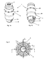
- Fig. 1a shows a first view of a rotary distributor 1.
- This rotary distributor 1 has a transport line 2, through which a medium, such as a drink, can be passed.
- the reference numeral 22 refers to a flange with which this transport line 2 can be flanged to a pipe.
- the reference numeral 4 refers in its entirety to a housing which is arranged around the transport line 2 around. In this case, the transport line 2 is usually arranged standing in operation and the housing 4, in contrast, rotating.
- Reference numeral 23 denotes an opening for supplying another medium, such as a cleaning liquid.
- the reference numeral 36 denotes a Opening for discharging a medium, such as the cleaning liquid.
- Fig. 1b shows another view of the in Fig. 1a It can be seen here that below the openings 36, a further series of openings 38 is provided. These openings 38 are also outlet openings for a medium, such as a liquid for CIP cleaning.
- Fig. 2 shows a plan view of the rotary distributor to illustrate in the Fig. 3-5 shown sections AA, BB and CC.
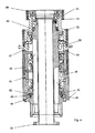
- Fig. 3 shows a section of the in Fig. 2 shown rotary distributor along the lines BB. It can be seen here, the transport line 2 and the rotatable about this transport line 2 arranged housing 4. Above the rotary distributor 1, a ring bowl (not shown) is also arranged to rotate.
- a plurality of ball bearings 19, 20 are present.
- a plurality of mechanical seals 16, 17 and 18 is provided.
- the seal means In order to improve the sealing, the seal means, denoted overall by 10, has, in addition to the mechanical seals 16-18, a channel 12 through which a sealing medium can flow.
- This channel is 12, as in Fig. 3 arranged so that the sealing medium, the ball bearing 19 and the mechanical seals 16 - 18 Maschinen- Maschinen- or flows around.
- Reference numerals 13 and 15 refer to two outlets for the sealing medium. To these outlets 13, 15 of the channel 12, which can be referred to as a back space, connect controllable valves 51 and sensor devices 14 and 14a and 24 and 24a.
- the sensor devices 14 and 14a and 24 and 24a can be provided alternatively or jointly.
- the reference numeral 11 denotes a collar screw for attaching leads (not shown).
- the reference numerals 26, 27 and 28 respectively refer to O-rings for sealing separate housing parts.
- the reference numeral 25 shows a retaining ring for the bearing 19th
- Fig. 3 also transport routes 55 and 56 for the cleaning medium and a CIP medium shown.
- the reference numeral 5 shows a supply line for the sealing medium, which is then introduced into the rear space or the channel 12.
- Fig. 4 shows a section of the rotary distributor Fig. 2 along the line AA.
- the reference numeral 48 refers to an upper part of the housing and the reference numeral 49 to a housing cover, said housing cover 49 is screwed by means of hexagonal screws 31 to the upper part of housing 48.
- the reference numeral 33 refers to a suspension device.
- the reference numeral 47 denotes another portion of the distributor housing having the above-mentioned openings 36.
- an intermediate ring 45 of the housing is connected to a further part 46 of the distributor housing, which has the openings 38.
- the reference numeral 43 denotes a lower part of the housing 4 and the reference numeral 44 a Lagerklemmflansch for its attachment. With hexagon screws 30 of this Lagererklemmflansch is attached to the lower portion 43 of the housing 4. A bearing clamping ring 42 locks the bearing 20.
- Fig. 5 shows a view of the rotary distributor along the line CC Fig. 2 ,
- the supply line 5 can be recognized, via which the sealing medium is supplied to the rear space or channel 12 by means of a line 7.
- a sensor device 64, 64a more precisely a flow rate measuring device 64 and / or a density measuring device 64a, can be provided at the inlet of this connection.
- the rotary distributor according to the invention is suitable both for applications in the field of aseptic and for standard applications, that is, applications in which no sterile gas must be used.
- the pressure of the product P p is higher than the atmospheric pressure P at . Furthermore, the pressure P 1 is higher than the pressure of the product P p .
- a sterile medium from the back space 12 can pass through a leakage opening in the product, since the pressure P 1 is greater than the pressure P p of the product.
- This case can be detected, in which both at the inlet 5 of the back space, a flow rate sensor 64 is arranged as well as to the (in Fig. 3 shown) drains a flow meter 14 and 24 is provided. If these flow rate sensors 14, 24 and 64 detect different flow rates, it can be concluded that there is a leak.
- the pressure P 1 in the back space 12 is higher than the atmospheric pressure P at and further the pressure of the product P p in the transport line 2 is higher than the pressure P 1 in the back space 12
- the product in the event of a leak, the product is pressed into the (sterile) rear space 12 and arrives in this way to the processes 13 and 15.
- the product forms in this case a so-called liquid bridge, which is to be regarded as critical.
- This ingress of product into the back space 12 can be detected by density sensors 24a, 14a, since the sterile gas at the entrance is not yet contaminated by the product and therefore has a different density than the gas at the exits 13 and 15. This can also be done this condition can be reliably recognized by the arrangements according to the invention. It would also be possible here to provide both density sensors and flow rate sensors.
- a third case of aseptic is as a product, which is guided in the transport line 2, also Sterile gas used.
- This may for example be a superposition gas, which is conveyed into a container.
- the case may occur that the pressure P 1 of the back space is greater than the atmospheric pressure P at and the pressure of the product P p in turn greater than the pressure P 1 of the back space 12.
- this case would in principle be with the second case described above comparable in which the penetration of product into the back space is recognizable by a density difference.
- a density difference can not be readily measured since the product itself is also a sterile gas. Therefore, this case can also be detected by a flow rate difference, as in the first case described above, since there will be more gas at the exit than at the entrance.
- the pressure of the medium in the back space 12 is equal to the atmospheric pressure P at , so that there may generally be two cases, on the one hand the case that the pressure P p of the product is less than the atmospheric pressure P at and on the other hand that the pressure of the product P p is greater than the atmospheric pressure.
- the case that the pressure P p of the product is less than the atmospheric pressure P at can basically only occur in the event of an evacuation, for example in the form of a vacuum trace when beer filling. However, this case is not critical because it can be detected by a collapse of the vacuum.
- the pressure of the product is higher than the atmospheric pressure.
- product enters the back space 12.
- the above-mentioned second case can be used, in which the entry of product into a back space 12 is detected by means of a density difference.
- the error case can be detected by a flow difference, as also described above (third case).
Abstract
Description
- Die vorliegende Erfindung bezieht sich auf eine Vorrichtung zum Verteilen von Medien und insbesondere eine Vorrichtung zum Verteilen von Flüssigkeiten. Im Bereich der getränkeherstellenden Industrie sind aus dem Stand der Technik Verteilbehältnisse für Getränke bekannt, welche das betreffende Getränk aus einem Behälter in eine Vielzahl von einzelnen Abfülleinrichtungen verteilen, damit diese Abfülleinrichtungen wiederum das Getränk in die zu befüllenden Behältnisse einbringen können. Auch ist es aus dem Stand der Technik bekannt, Behältnisse mit gasförmigen Substanzen wie beispielsweise Wasserstoffperoxidgas, Sterilluft oder Heißluft zu befüllen, bevor sie mit dem eigentlichen Medium, wie dem Getränk, befüllt werden.
- Dabei ist es bei manchen aus dem Stand der Technik bekannten Ausführungsformen üblich, dass die Leitung, durch welche hindurch das Getränk eingefüllt wird, stationär angeordnet ist und sich das Behältnis, in welches das Getränk eingefüllt wird, demgegenüber dreht. Zu diesem Zweck ist es nötig, die entsprechenden stationär angeordneten Bestandteile der Anordnung gegenüber den rotierend angeordneten Bestandteilen abzudichten. Dazu wird teilweise ein Sperrmedium oder ein Dichtungsmedium eingesetzt, welches zwischen den stationären und den rotierenden Teilen der Anordnung strömt und welche eine Abdichtung des stationären Bereichs bewirkt und auch verhindert, dass von außen Fremdstoffe in die abzufüllenden Behältnisse gelangen können.
- Derartige Dichtungseinrichtungen, bei denen es sich beispielsweise um Gleitringdichtungen handelt, arbeiten im Stand der Technik zufriedenstellend. Allerdings kann es infolge unterschiedlicher Effekte zu Ausfällen dieser Dichtung kommen. Wenn ein derartiger Ausfall nicht rechtzeitig detektiert wird, kann in der Folge das abzufüllende Medium kontaminiert werden.
- Der vorliegenden Erfindung liegt daher die Aufgabe zugrunde, einen Drehverteiler zur Verfügung zu stellen, der in seiner Betriebszuverlässigkeit gegenüber dem Stand der Technik verbessert ist. Genauer gesagt, soll ein Drehverteiler zur Verfügung gestellt werden, der Ausfälle der Dichtungseinrichtung erkennt.
- Dies wird erfindungsgemäß durch einen Drehverteiler nach Anspruch 1 und ein Verfahren zum Betreiben eines Drehverteilers nach Anspruch 12 erreicht. Vorteilhafte Ausführungsformen und Weiterbildungen sind Gegenstand der Unteransprüche.
- Ein erfindungsgemäßer Drehverteiler weist eine Transportleitung zum Befördern eines Medium auf, sowie ein Gehäuse, wobei das Gehäuse die Transportleitung wenigstens abschnittsweise umgibt und wobei die Transportleitung stationär gegenüber dem drehbaren Gehäuse angeordnet ist. Weiterhin ist eine Dichtungseinrichtung vorgesehen, welche die Transportleitung insbesondere gegenüber der Umgebung abdichtet, wobei die Dichtungseinrichtung einen Kanal aufweist, innerhalb dessen ein Dichtungsmedium fließen kann.
- Erfindungsgemäß weist der Drehverteiler wenigstens eine erste Sensoreinrichtung auf, welche eine physikalische Eigenschaft des Dichtungsmediums erfasst und welche ein Messsignal ausgibt, welches für diese physikalische Eigenschaft charakteristisch ist.
- Über die Transportleitung wird insbesondere ein Getränk gefördert und beispielsweise in ein sich drehendes Behältnis eingeführt. Es wäre jedoch auch möglich, über die Transportleitung ein gasförmiges Medium zu führen. Vorzugsweise ist die Transportleitung stationär angeordnet und das Behältnis dreht sich ihr gegenüber. Die Anordnung kann aber auch umgekehrt mit stehendem Behältnis und drehender Transportleitung ausgeführt sein. Die Dichtungseinrichtung verhindert, dass unerwünschte Medien zusätzlich in das Behältnis eindringen können. Weiterhin verhindert die Dichteinrichtung ein ungewolltes Austreten des Getränks. Unter der Dichtungseinrichtung werden nicht nur Dichtungselemente im engeren Sinn verstanden, wie etwa Gleitringdichtungen, sondern die Gesamtheit der Elemente, welche diese Dichtwirkung erreichen bzw. fördern, wie beispielsweise der Kanal.
- Bei dem Kanal handelt es sich vorzugsweise um einen zwischen den drehbaren und den nicht drehbaren Teilen angeordneten Kanal. Dieser Kanal umgibt bevorzugt die Transportleitung vollständig. Vorzugsweise handelt es sich bei dem Dichtungsmedium um ein gasförmiges Medium vorzugsweise um ein steriles Medium und besonders bevorzugt um ein steriles Gas. Es wäre jedoch auch möglich, ein nicht steriles Gas als Dichtungsmedium einzusetzen. Die Sensoreinrichtung erfasst, wie ausgeführt, wenigstens eine physikalische Eigenschaft des Dichtungsmediums und kann aufgrund dieser Messung feststellen, ob beispielsweise ein Anteil des Dichtungsmediums verloren gegangen ist, oder ob eine Flüssigkeit aus der Transportleitung ungewollt in das Dichtungsmedium eingetreten ist.
- Vorzugsweise sind das Dichtungsmedium und das in der Transportleitung geführte Medium vollständig getrennt voneinander und vorzugsweise handelt es sich um voneinander unterschiedliche Medien.
- Vorzugsweise handelt es sich bei der physikalischen Eigenschaft um eine Dichte des Dichtungsmediums. Falls beispielsweise Flüssigkeit aus der Transportleitung in den Kanal tritt, wird sich dies in der Dichte des Dichtungsmediums bemerkbar machen. In diesem Falle können geeignete Gegenmaßnahmen eingeleitet werden.
- Vorzugsweise ist die Sensoreinrichtung stromabwärts bezüglich eines Auslasses des Dichtungsmediums aus dem Kanal angeordnet. Unter stromabwärts wird dabei eine Strömungsrichtung im Bezug auf das Dichtungsmedium verstanden. Es wäre jedoch auch möglich, eine Sensoreinrichtung beispielsweise unmittelbar nach dem Auslass der Dichtung anzuordnen. Damit ist hier die Sensoreinrichtung nach dem Kanal bzw. Rückraum angeordnet. Es wäre jedoch auch möglich, eine Sensoreinrichtung vor dem Kanal und eine Sensoreinrichtung nach dem Kanal anzuordnen.
- Bei einer weiteren vorteilhaften Ausführungsform weist der Drehverteiler wenigstens ein Dichtelement auf, welches die Transportleitung gegenüber dem Gehäuse abdichtet, bzw. welches die drehenden Teile des Drehverteilers gegenüber den stehenden Teilen abdichtet. Bei diesem Dichtelement handelt es sich besonders bevorzugt um eine Gleitringdichtung, welche diese Dichtwirkung auch während der Drehbewegung des Gehäuses gegenüber der Transportleitung aufrechterhält. Vorteilhaft sind mehrere derartige Dichtelemente, besonders bevorzugt jeweils in Form von Gleitringdichtungen vorgesehen.
- Bei einer weiteren vorteilhaften Ausführungsform ist wenigstens eine Sensoreinrichtung aus einer Gruppe von Sensoreinrichtungen ausgewählt, welche induktiv arbeitende Sensoreinrichtungen, Biegerschwingersensoreinrichtungen und dergleichen aufweist. Als besonders geeignet hat sich eine sogenannte Biegerschwingersensoreinrichtung gezeigt. Dabei wird ein Biegerschwinger mittels eines Piezoelements in Schwingung versetzt. Die Schwingungsfrequenz dieses Biegerschwingers steht dabei in direktem Zusammenhang mit der Dichte der eingeführten Probe. Je höher die Dichte, desto niedriger wird die Frequenz dieses Biegeschwingers ausfallen. Aus diesem Zusammenhang wird über die gemessene Frequenz des Biegerschwingers direkt die Dichte der Probe ermittelt.
- Bei einer weiteren bevorzugten Ausführungsform weist die Dichtungseinrichtung eine zweite Sensoreinrichtung auf. Bei dieser Ausführungsform sind besonders bevorzugt die Sensoreinrichtungen an Eingang und Ausgang des Kanals angeordnet. So ist es möglich, durch einen Vergleich der von den Sensoreinrichtungen ausgegebenen Signale auf mögliche Leckagen des Kanals und damit der Dichtungseinrichtung zu lesen.
- Bei einer weiteren vorteilhaften Ausführungsform ist eine Vergleichseinrichtung vorgesehen, die die Messsignale der beiden Sensoreinrichtungen miteinander vergleicht. Aus diesem Vergleich kann, wie oben erwähnt, auf Leckagen innerhalb der Dichtungseinrichtung geschlossen werden.
- Bei einer weiteren vorteilhaften Ausführungsform weist die Vorrichtung wenigstens zwei Sensoreinrichtungen unterschiedlicher Gattung auf. So kann beispielsweise sowohl eine Sensoreinrichtung zur Bestimmung einer Dichte vorhanden sein, als auch eine Sensoreinrichtung zur Ermittlung einer Durchflussmenge. Damit ist es möglich, den Drehverteiler flexibel hinsichtlich der verwendeten Substanzen zu gestalten und insbesondere flexibel hinsichtlich sowohl gasförmigen als auch flüssigen Substanzen.
- So wäre es beispielsweise möglich, dass zwei Sensoreinrichtungen in Form von Durchflussmengensensoren und eine Sensoreinrichtung in Form einer Dichtemesseinrichtung vorgesehen sind.
- Die vorliegende Erfindung ist weiterhin auf ein Verfahren zum Betreiben eines Drehverteilers gerichtet, wobei mit Hilfe einer Transportleitung ein Medium transportiert wird, und wenigstens abschnittsweise um diese Transportleitung herum ein Gehäuse angeordnet ist, wobei sich das Gehäuse gegenüber der Transportleitung dreht und wobei eine Dichtungseinrichtung die Transportleitung gegenüber dem Gehäuse abdichtet und diese Dichtungseinrichtung einen Kanal aufweist, innerhalb dessen ein Dichtungsmedium fließt. Erfindungsgemäß wird mittels einer ersten Sensoreinrichtung eine physikalische Eigenschaft des Dichtungsmediums erfasst und ein Messsignal ausgegeben, welches für diese physikalische Eigenschaft charakteristisch ist.
- Weitere Vorteile und Ausführungsformen ergeben sich aus den beigefügten Zeichnungen:
- Darin zeigen:
- Fig. 1a
- Eine erste Darstellung eines Drehverteilers;
- Fig. 1b
- Den Drehverteiler aus
Fig. 1a in einer weiteren Perspektive; - Fig. 2
- Eine Draufsicht auf einen erfindungsgemäßen Drehverteiler;
- Fig. 3
- Eine Ansicht des Drehverteilers aus
Fig. 2 entlang der Linien B-B ausFig. 2 ; - Fig. 4
- Eine Ansicht des Drehverteilers aus
Fig. 2 entlang der Linien A-A ausFig. 2 ; und - Fig. 5
- Eine Ansicht des Drehverteilers entlang der Linien C-C aus
Fig. 2 .
-
Fig. 1a zeigt eine erste Ansicht eines Drehverteilers 1. Dieser Drehverteiler 1 weist eine Transportleitung 2 auf, durch welche hindurch ein Medium, wie beispielsweise ein Getränk, geführt werden kann. Das Bezugszeichen 22 bezieht sich auf einen Flansch, mit dem diese Transportleitung 2 an einem Rohr angeflanscht werden kann. Das Bezugszeichen 4 bezieht sich in seiner Gesamtheit auf ein Gehäuse, welches um die Transportleitung 2 herum angeordnet ist. Dabei ist im Betrieb üblicherweise die Transportleitung 2 stehend angeordnet und das Gehäuse 4 demgegenüber drehend. - Das Bezugszeichen 23 kennzeichnet eine Öffnung, um ein weiteres Medium zuzuführen, wie beispielsweise eine Reinigungsflüssigkeit. Das Bezugszeichen 36 kennzeichnet eine Öffnung zum Abführen eines Mediums, wie beispielsweise der Reinigungsflüssigkeit.
-
Fig. 1b zeigt eine weitere Ansicht des inFig. 1a gezeigten Drehverteilers 1. Man erkennt hier, dass unterhalb der Öffnungen 36 eine weitere Reihe an Öffnungen 38 vorgesehen ist. Bei diesen Öffnungen 38 handelt es sich ebenfalls um Austrittsöffnungen für ein Medium wie beispielsweise eine Flüssigkeit für eine CIP-Reinigung. -
Fig. 2 zeigt eine Draufsicht auf den Drehverteiler zur Veranschaulichung der in denFig. 3 - 5 gezeigten Schnitte A-A, B-B und C-C. -
Fig. 3 zeigt einen Schnitt des inFig. 2 gezeigten Drehverteilers entlang der Linien B-B. Man erkennt auch hier die Transportleitung 2 und das drehbar um diese Transportleitung 2 angeordnete Gehäuse 4. Oberhalb des Drehverteilers 1 ist ein Ringkessel (nicht gezeigt) ebenfalls drehend angeordnet. - Zur drehbaren Anordnung des Gehäuses 4 gegenüber der Transportleitung 2 sind mehrere Kugellager 19, 20 vorhanden. Zum Abdichten des Gehäuses gegenüber der Transportleitung ist eine Vielzahl von Gleitringdichtungen 16, 17 und 18 vorgesehen.
- Um die Abdichtung zu verbessern, weist die in ihrer Gesamtheit mit 10 bezeichnete Dichtungseinrichtung neben den Gleitringdichtungen 16 - 18 einen Kanal 12 auf, durch den ein Dichtungsmedium strömen kann. Dabei ist dieser Kanal 12, wie in
Fig. 3 gezeigt, so angeordnet, dass das Dichtungsmedium das Kugellager 19 und die Gleitringdichtungen 16 - 18 durch- bzw. umströmt. Die Bezugszeichen 13 und 15 beziehen sich auf zwei Auslässe für das Dichtungsmedium. An diese Auslässe 13, 15 des Kanals 12, der als Rückraum bezeichnet werden kann, schließen sich regelbare Ventile 51 und Sensoreinrichtungen 14 bzw. 14a und 24 bzw. 24a an. Die Sensoreinrichtungen 14 und 14a sowie 24 und 24a können dabei alternativ oder auch gemeinsam vorgesehen sein. - Das Bezugszeichen 11 kennzeichnet eine Bundschraube zum Anbringen von Leitungen (nicht gezeigt). Die Bezugszeichen 26, 27 und 28 beziehen sich jeweils auf O-Ringe zum Abdichten voneinander getrennter Gehäuseteile. Das Bezugszeichen 25 zeigt einen Sicherungsring für das Lager 19.
- Weiterhin sind in
Fig. 3 auch Transportwege 55 und 56 für das Reinigungsmedium und ein CIP-Medium dargestellt. Das Bezugszeichen 5 zeigt eine Zuleitung für das Dichtungsmedium, welches anschließend in den Rückraum bzw. den Kanal 12 eingeführt wird. -
Fig. 4 zeigt einen Schnitt des Drehverteilers ausFig. 2 entlang der Linie A-A. Dabei bezieht sich das Bezugszeichen 48 auf ein oberes Teilgehäuse und das Bezugszeichen 49 auf einen Gehäusedeckel, wobei dieser Gehäusedeckel 49 mittels Sechskantschrauben 31 an dem oberen Teilgehäuse 48 angeschraubt ist. Das Bezugszeichen 33 bezieht sich auf eine Federungseinrichtung. - Das Bezugszeichen 47 kennzeichnet einen weiteren Bereich des Verteilergehäuses, welches die oben erwähnten Öffnungen 36 aufweist. Mittels einer Zylinderschraube 66 ist ein Zwischenring 45 des Gehäuses mit einem weiteren Teil 46 des Verteilergehäuses, der die Öffnungen 38 aufweist, verbunden.
- Das Bezugszeichen 43 kennzeichnet einen unteren Teil des Gehäuses 4 und das Bezugszeichen 44 einen Lagerklemmflansch zu dessen Befestigung. Mit Sechskantschrauben 30 ist dieser Lagerklemmflansch an dem unteren Bereich 43 des Gehäuses 4 befestigt. Ein Lagerklemmring 42 arretiert das Lager 20.
-
Fig. 5 zeigt eine Ansicht des Drehverteilers entlang der Linie C-C ausFig. 2 . Man erkennt hier wiederum die Zuleitung 5, über welche mittels einer Leitung 7 dem Rückraum bzw. Kanal 12 das Dichtungsmedium zugeführt wird. An dem Eingang dieses Anschlusses kann wiederum eine Sensoreinrichtung 64, 64a, genauer eine Durchflussmengenmesseinrichtung 64 und/oder eine Dichtenmesseinrichtung 64a vorgesehen sein. - Unter Bezugnahme auf die
Fig. 3 - 5 wird nunmehr die Anordnung der einzelnen Sensoreinrichtungen 14, 14a, 24, 24a, 64, 64a dargestellt. - Der erfindungsgemäße Drehverteiler ist sowohl für Anwendungen im Bereich der Aseptik als auch für Standardanwendungen, das heißt Anwendungen, bei denen kein Sterilgas verwendet werden muss, geeignet.
- Im Bereich der Aseptik treten drei verschiedene Drücke auf, nämlich zum einen ein Produktdruck Pp (in der Transporteinrichtung 2), ein Druck P1 innerhalb des Rückraums 12 und ein atmosphärischer Druck Pat außerhalb des Drehverteilers.
- In einem ersten Fall ist der Druck des Produkts Pp höher als der atmosphärische Druck Pat. Weiterhin ist der Druck P1 höher als der Druck des Produkts Pp. Hier kann der Fall eintreten, dass ein steriles Medium aus dem Rückraum 12 durch eine Leckageöffnung in das Produkt gelangen kann, da der Druck P1 größer ist als der Druck Pp des Produkts. Dieser Fall kann detektiert werden, in dem sowohl an dem Zulauf 5 des Rückraums ein Durchflussmengen-sensor 64 angeordnet ist als auch an den (in
Fig. 3 gezeigten) Abflüssen ein Durchflussmessgerät 14 bzw. 24 vorgesehen ist. Falls diese Durchflussmengensensoren 14, 24 und 64 unterschiedliche Durchflussmengen detektieren, kann hieraus auf ein Leck geschlossen werden. - Dieser Fall ist jedoch als unkritisch einzustufen, da hier lediglich steriles Medium in das Produkt gedrückt wird.
- Bei einem zweiten Fall ist es denkbar, dass der Druck P1 in dem Rückraum 12 höher ist als der atmosphärische Druck Pat und weiterhin der Druck des Produkts Pp in der Transportleitung 2 höher ist als der Druck P1 in dem Rückraum 12. In diesem Falle wird im Falle einer Leckage das Produkt in den (sterilen) Rückraum 12 gepresst und gelangt auf diese Weise zu den Abläufen 13 und 15. Das Produkt bildet in diesem Fall eine sogenannte Flüssigkeitsbrücke, was als kritisch anzusehen ist. Dieses Eindringen von Produkt in den Rückraum 12 kann durch Dichtesensoren 24a, 14a detektiert werden, da das sterile Gas am Eingang noch nicht durch das Produkt kontaminiert ist und daher eine andere Dichte aufweist als das Gas an den Ausgängen 13 und 15. Damit lässt sich auch dieser Zustand durch die erfindungsgemäßen Anordnungen sicher erkennen. Dabei wäre es hier auch möglich, sowohl Dichtesensoren als auch Durchflussmengensensoren vorzusehen.
- In einem denkbaren dritten Fall der Aseptik wird als Produkt, welches in der Transportleitung 2 geführt wird, ebenfalls Sterilgas verwendet. Dabei kann es sich beispielsweise um ein Überlagerungsgas handeln, welches in ein Behältnis gefördert wird. Dabei kann der Fall auftreten, dass der Druck P1 des Rückraums größer ist als der atmosphärische Druck Pat und der Druck des Produkts Pp wiederum größer als der Druck P1 des Rückraums 12. Dieser Fall wäre zwar grundsätzlich mit dem oben beschriebenen zweiten Fall vergleichbar in dem das Eindringen von Produkt in den Rückraum durch eine Dichtedifferenz erkennbar ist. Hier kann jedoch eine Dichtedifferenz nicht ohne weiteres gemessen werden, da es sich bei dem Produkt selbst ebenfalls um ein Sterilgas handelt. Daher kann dieser Fall ebenfalls durch eine Durchflussmengendifferenz, wie in dem oben beschriebenen ersten Fall erkannt werden, da am Ausgang mehr Gas vorhanden sein wird als am Eingang.
- Auf diese Weise sind alle im Fall der Aseptik möglichen Dichtigkeitsfehler erkennbar.
- Bei nichtaseptischen Anwendungen ist der Druck des Mediums in dem Rückraum 12 gleich dem atmosphärischen Druck Pat, so dass hier generell zwei Fälle auftreten können, nämlich einerseits der Fall, dass der Druck Pp des Produkts kleiner ist als der atmosphärische Druck Pat und andererseits dass der Druck des Produkts Pp größer ist als der atmosphärische Druck. Der Fall, dass der Druck Pp des Produkts kleiner ist als der atmosphärische Druck Pat kann grundsätzlich nur im Falle einer Evakuierung auftreten beispielsweise in Form einer Vakuumspur beim Bierfüllen. Dieser Fall ist jedoch unkritisch, da er durch einen Zusammenbruch des Vakuums erkannt werden kann.
- In dem anderen Fall ist der Druck des Produkts höher als der atmosphärische Druck. Auch in diesem Falle gelangt Produkt in den Rückraum 12. Falls es sich dabei um ein flüssiges Produkt handelt, kann der oben erwähnte zweite Fall herangezogen werden, in dem das Eintreten von Produkt in einen Rückraum 12 über einen Dichteunterschied erkannt wird. In dem Fall, in dem es sich bei dem Produkt um ein gasförmiges Produkt handelt, kann hier der Fehlerfall durch eine Durchflussdifferenz erkannt werden, wie ebenfalls oben beschrieben (dritter Fall).
- Damit kann durch die erfindungsgemäße Vorrichtung insgesamt unabhängig von der Anwendung jeweils eine 100%-ige Erkennung eines Dichtungsschadens erreicht werden und damit auch die Möglichkeit eines sicheren Stilllegens der Maschine im Fehlerfall.
- Sämtliche in den Anmeldungsunterlagen offenbarten Merkmale werden als erfindungswesentlich beansprucht, sofern sie einzeln oder in Kombination gegenüber dem Stand der Technik neu sind.
Claims (15)
- Drehverteiler (1) mit einer Transportleitung (2) zum Befördern eines Mediums, mit einem Gehäuse (4) wobei das Gehäuse (4) die Transportleitung (2) wenigstens abschnittsweise umgibt und wobei das Gehäuse (4) drehbar gegenüber der Transportleitung (2) angeordnet ist, und mit einer Dichtungseinrichtung (10), um die Transportleitung (2) abzudichten, wobei die Dichtungseinrichtung (10) einen Kanal (12) aufweist, innerhalb dessen ein Dichtungsmedium fließen kann,
dadurch gekennzeichnet, dass
der Drehverteiler (1) wenigstens eine erste Sensoreinrichtung (14, 14a, 24, 24a, 64, 64a) aufweist, welche wenigstens eine physikalische Eigenschaft des Dichtungsmediums erfasst und welche ein Messsignal ausgibt, welches für diese physikalische Eigenschaft charakteristisch ist. - Drehverteiler (1) nach Anspruch 1,
dadurch gekennzeichnet, dass
die physikalische Eigenschaft eine Dichte des Dichtungsmediums oder eine Durchflussmenge des Dichtungsmediums ist. - Drehverteiler (1) nach wenigstens einem der vorangegangenen Ansprüche,
dadurch gekennzeichnet, dass
das Dichtungsmedium ein gasförmiges Medium ist. - Drehverteiler (1) nach wenigstens einem der Ansprüche 1 bis 3,
dadurch gekennzeichnet, dass
das Dichtungsmedium ein flüssiges Medium ist. - Drehverteiler (1) nach wenigstens einem der Ansprüche 4 bis 5,
dadurch gekennzeichnet, dass
das Medium steril ist. - Drehverteiler (1) nach wenigstens einem der vorangegangenen Ansprüche,
dadurch gekennzeichnet, dass
das Dichtungsmedium ein steriles Gas ist. - Drehverteiler (1) nach wenigstens einem der vorangegangenen Ansprüche,
dadurch gekennzeichnet, dass
der Drehverteiler wenigstens ein Dichtelement (16, 17, 18) aufweist, welches die Transportleitung (2) gegenüber dem Gehäuse (4) abdichtet. - Drehverteiler (1) nach wenigstens einem der vorangegangenen Ansprüche,
dadurch gekennzeichnet, dass
die Sensoreinrichtung (14) stromabwärts bezüglich eines Auslasses (13, 15) des Dichtungsmediums aus dem Kanal (12) angeordnet ist. - Drehverteiler (1) nach wenigstens einem der vorangegangenen Ansprüche,
dadurch gekennzeichnet, dass
der Drehverteiler (1) eine zweite Sensoreinrichtung (24) aufweist. - Drehverteiler (1) nach Anspruch 7,
dadurch gekennzeichnet, dass
beide Sensoreinrichtungen (14, 24) an Ausgängen (13, 15) des Kanals (12) angeordnet sind. - Drehverteiler (1) nach wenigstens einem der vorangegangenen Ansprüche,
dadurch gekennzeichnet, dass
wenigstens eine Sensoreinrichtung (14a, 24a, 64a) aus einer Gruppe von Sensoreinrichtungen ausgewählt ist, welche induktiv arbeitende Sensoreinrichtungen, Biegeschwinger - Sensoreinrichtungen und dergleichen aufweist. - Drehverteiler nach wenigstens einem der vorangegangenen Ansprüche,
dadurch gekennzeichnet, dass
der Drehverteiler (1) eine Steuerungseinrichtung aufweist, welche einen Antriebs des Drehverteilers in Reaktion auf ein von einer Sensoreinrichtung (14, 14a, 24, 24a, 64, 64a) ausgegebenes Messsignal steuert. - Drehverteiler (1) nach wenigstens einem der vorangegangenen Ansprüche 7 - 10,
dadurch gekennzeichnet, dass
eine Vergleichseinrichtung vorgesehen ist, welche die Messsignale der beiden Sensoreinrichtungen (14, 64) vergleicht. - Drehverteiler (1) nach wenigstens einem der vorangegangenen Ansprüche,
dadurch gekennzeichnet, dass
zwei Sensoreinrichtungen (14, 14a) vorgesehen sind, welche unterschiedliche Eigenschaften des Dichtungsmediums erfassen. - Verfahren zum Betreiben eines Drehverteilers (1), wobei mit Hilfe einer Transportleitung (2) ein Medium transportiert wird und wobei wenigstens abschnittsweise um diese Transportleitung (2) herum ein Gehäuse (4) angeordnet ist, wobei sich die Transportleitung (2) gegenüber dem Gehäuse (4) dreht und wobei eine Dichtungseinrichtung (10) die Transportleitung (2) gegenüber dem Gehäuse (4) abdichtet und diese Dichtungseinrichtung (10) einen Kanal (12) aufweist, innerhalb dessen ein Dichtungsmedium fließt;
dadurch gekennzeichnet, dass
mittels einer ersten Sensoreinrichtung (14, 14a, 24, 24a, 64, 64a) eine physikalische Eigenschaft des Dichtungsmediums (B) erfasst wird und ein Messsignal ausgegeben wird, welches für diese physikalische Eigenschaft charakteristisch ist.
Applications Claiming Priority (1)
| Application Number | Priority Date | Filing Date | Title |
|---|---|---|---|
| DE200710060392 DE102007060392A1 (de) | 2007-12-14 | 2007-12-14 | Drehverteiler mit Leckageerkennung |
Publications (2)
| Publication Number | Publication Date |
|---|---|
| EP2070865A1 true EP2070865A1 (de) | 2009-06-17 |
| EP2070865B1 EP2070865B1 (de) | 2015-12-09 |
Family
ID=40430350
Family Applications (1)
| Application Number | Title | Priority Date | Filing Date |
|---|---|---|---|
| EP08171029.5A Active EP2070865B1 (de) | 2007-12-14 | 2008-12-09 | Drehverteiler mit Leckageerkennung |
Country Status (2)
| Country | Link |
|---|---|
| EP (1) | EP2070865B1 (de) |
| DE (1) | DE102007060392A1 (de) |
Cited By (9)
| Publication number | Priority date | Publication date | Assignee | Title |
|---|---|---|---|---|
| CN102756814A (zh) * | 2012-07-31 | 2012-10-31 | 广州达意隆包装机械股份有限公司 | 一种灌装机的中心分配器 |
| WO2012150513A1 (en) | 2011-05-02 | 2012-11-08 | Gea Procomac S.P.A. | A rotary fluid dispenser |
| EP3015416A1 (de) * | 2014-10-31 | 2016-05-04 | Sidel Participations S.A.S. | Verteiler für eine Fülleinheit zum Befüllen von mehreren Artikeln mit einem fließfähigen Produkt |
| EP3040306A1 (de) * | 2014-12-29 | 2016-07-06 | Sidel Participations, S.A.S. | Verteiler für einen drehbaren Tank für eine Fülleinheit zum Befüllen von mehreren Artikeln mit einem fließfähigen Produkt |
| WO2018187353A1 (en) * | 2017-04-03 | 2018-10-11 | Abbott Laboratories | Rotary filling machines |
| WO2019012116A1 (de) * | 2017-07-14 | 2019-01-17 | Krones Ag | Vorrichtung zum behandeln eines behälters in einer füllproduktabfüllanlage |
| EP3594172A1 (de) * | 2018-07-12 | 2020-01-15 | Sidel Participations | Verteileranordnung für eine füllmaschine und verfahren zum füllen eines behälters mit einem fliessfähigen produkt |
| EP3521237A4 (de) * | 2016-09-30 | 2020-06-03 | Dai Nippon Printing Co., Ltd. | Aseptisches abfüllsystem für kohlensäurehaltige getränke sowie aseptisches abfüllverfahren für kohlensäurehaltige getränke |
| IT202100010772A1 (it) * | 2021-04-28 | 2022-10-28 | S A T S R L | Organo per il convogliamento di un corrispondente fluido |
Families Citing this family (2)
| Publication number | Priority date | Publication date | Assignee | Title |
|---|---|---|---|---|
| DE102013110016A1 (de) * | 2013-09-12 | 2015-03-12 | Khs Gmbh | Drehdurchführung sowie Vorrichtung zur Behandlung und/oder zum Transport von Behältern mit einer solchen Drehdurchführung |
| DE102019219430A1 (de) * | 2019-12-12 | 2021-06-17 | Eagleburgmann Germany Gmbh & Co. Kg | Gleitringdichtungsanordnung mit Leckagemessung |
Citations (2)
| Publication number | Priority date | Publication date | Assignee | Title |
|---|---|---|---|---|
| DE29620323U1 (de) * | 1996-11-22 | 1997-01-23 | Kronseder Maschf Krones | Drehverteiler für rotierende Gefäßfüllmaschinen |
| WO2008019831A1 (de) | 2006-08-17 | 2008-02-21 | Khs Ag | Dichtanordnung für eine drehlagervorrichtung |
Family Cites Families (16)
| Publication number | Priority date | Publication date | Assignee | Title |
|---|---|---|---|---|
| DE3426833A1 (de) | 1984-07-20 | 1986-01-23 | W.L. Gore & Co GmbH, 8011 Putzbrunn | Lecksuchvorrichtung fuer saure und basische medien |
| US4557139A (en) | 1984-07-31 | 1985-12-10 | Loomis International Inc. | Leak detection method and apparatus |
| DE19521018C2 (de) | 1995-06-12 | 1997-04-17 | Bernd Brandes | Rohrleitungssystem, insbesondere für die Übertragung von Fernwärme |
| US6112579A (en) | 1997-08-25 | 2000-09-05 | Tryba; Stephen A. | Fluid leakage sensors |
| DE19841717C2 (de) | 1998-09-11 | 2001-11-29 | Gore W L & Ass Gmbh | Elektrische Sensorleitung zur Leckageerkennung |
| DE10060976B4 (de) | 2000-12-06 | 2005-06-23 | Framatome Anp Gmbh | Vorrichtung zur Leckageerkennung und Leckageortung |
| US20030037596A1 (en) | 2001-06-28 | 2003-02-27 | Sorensen Peter K. | Leakage detection system for gas pipelines |
| DE20120014U1 (de) * | 2001-12-11 | 2003-02-06 | Krones Ag | Rotationsfüller |
| US7500489B2 (en) | 2002-08-23 | 2009-03-10 | Ameron International Corporation | Contained pipeline system with brine filled interstitial space and method for detecting leakage in same |
| ITPR20030001A1 (it) | 2003-01-17 | 2004-07-18 | Sig Technology Ltd | Macchina per il trattamento in asettico di contenitori |
| US7299681B2 (en) | 2004-09-27 | 2007-11-27 | Idc, Llc | Method and system for detecting leak in electronic devices |
| DE102005007988A1 (de) | 2005-02-22 | 2006-08-24 | Framatome Anp Gmbh | Sammelleitung zur Leckageüberwachung und Leckageortung |
| DE102005036338A1 (de) | 2005-07-29 | 2007-02-15 | Wilo Ag | Gleitringdichtung |
| DE202006000325U1 (de) * | 2006-01-11 | 2006-03-16 | Krones Ag | Drehverteiler für Füller |
| DE102006007481B3 (de) * | 2006-02-17 | 2007-07-12 | Khs Ag | Anlage zum kaltaseptischen Abfüllen eines flüssigen Füllgutes in Flaschen oder dergleichen Behälter |
| DE102007041684A1 (de) * | 2007-09-01 | 2009-03-05 | Krones Ag | Medienverteilvorrichtung |
-
2007
- 2007-12-14 DE DE200710060392 patent/DE102007060392A1/de not_active Ceased
-
2008
- 2008-12-09 EP EP08171029.5A patent/EP2070865B1/de active Active
Patent Citations (2)
| Publication number | Priority date | Publication date | Assignee | Title |
|---|---|---|---|---|
| DE29620323U1 (de) * | 1996-11-22 | 1997-01-23 | Kronseder Maschf Krones | Drehverteiler für rotierende Gefäßfüllmaschinen |
| WO2008019831A1 (de) | 2006-08-17 | 2008-02-21 | Khs Ag | Dichtanordnung für eine drehlagervorrichtung |
Cited By (14)
| Publication number | Priority date | Publication date | Assignee | Title |
|---|---|---|---|---|
| WO2012150513A1 (en) | 2011-05-02 | 2012-11-08 | Gea Procomac S.P.A. | A rotary fluid dispenser |
| CN102756814B (zh) * | 2012-07-31 | 2014-03-12 | 广州达意隆包装机械股份有限公司 | 一种灌装机的中心分配器 |
| CN102756814A (zh) * | 2012-07-31 | 2012-10-31 | 广州达意隆包装机械股份有限公司 | 一种灌装机的中心分配器 |
| EP3015416A1 (de) * | 2014-10-31 | 2016-05-04 | Sidel Participations S.A.S. | Verteiler für eine Fülleinheit zum Befüllen von mehreren Artikeln mit einem fließfähigen Produkt |
| US20160122170A1 (en) * | 2014-10-31 | 2016-05-05 | Sidel Participations S.A.S. | Manifold for a filling unit for filling a plurality of articles with a pourable product |
| EP3040306A1 (de) * | 2014-12-29 | 2016-07-06 | Sidel Participations, S.A.S. | Verteiler für einen drehbaren Tank für eine Fülleinheit zum Befüllen von mehreren Artikeln mit einem fließfähigen Produkt |
| EP3521237A4 (de) * | 2016-09-30 | 2020-06-03 | Dai Nippon Printing Co., Ltd. | Aseptisches abfüllsystem für kohlensäurehaltige getränke sowie aseptisches abfüllverfahren für kohlensäurehaltige getränke |
| US11279606B2 (en) | 2016-09-30 | 2022-03-22 | Dai Nippon Printing Co., Ltd. | Sterile carbonated beverage filling system and sterile carbonated beverage filling method |
| CN113428821A (zh) * | 2016-09-30 | 2021-09-24 | 大日本印刷株式会社 | 碳酸饮料填充装置 |
| WO2018187353A1 (en) * | 2017-04-03 | 2018-10-11 | Abbott Laboratories | Rotary filling machines |
| CN110944933A (zh) * | 2017-07-14 | 2020-03-31 | 克罗内斯股份公司 | 用于处理在填充产品罐装设备中的容器的装置 |
| WO2019012116A1 (de) * | 2017-07-14 | 2019-01-17 | Krones Ag | Vorrichtung zum behandeln eines behälters in einer füllproduktabfüllanlage |
| EP3594172A1 (de) * | 2018-07-12 | 2020-01-15 | Sidel Participations | Verteileranordnung für eine füllmaschine und verfahren zum füllen eines behälters mit einem fliessfähigen produkt |
| IT202100010772A1 (it) * | 2021-04-28 | 2022-10-28 | S A T S R L | Organo per il convogliamento di un corrispondente fluido |
Also Published As
| Publication number | Publication date |
|---|---|
| DE102007060392A1 (de) | 2009-06-18 |
| EP2070865B1 (de) | 2015-12-09 |
Similar Documents
| Publication | Publication Date | Title |
|---|---|---|
| EP2070865B1 (de) | Drehverteiler mit Leckageerkennung | |
| EP2620406B1 (de) | Einfülleinrichtung zum Befüllen von Behältnissen | |
| EP2272790B1 (de) | Vorrichtung und Verfahren zum Abfüllen mehrkomponentiger Getränke | |
| EP3074680B1 (de) | Ventil | |
| EP2030941B1 (de) | Medienverteilvorrichtung | |
| EP1941267A2 (de) | Armatur zur aufnahme einer sonde | |
| EP2375224A1 (de) | Ultraschallmessvorrichtung und Verfahren zur Messung der Strömungsgeschwindigkeit eines Fluids | |
| EP2307304B1 (de) | Füllsystem | |
| EP2455106A1 (de) | Verdampfer zum Sterilisieren von Kunststoffbehältern | |
| EP0647842A1 (de) | Verfahren und Vorrichtung zur Erkennung eines Lecks in einem Behälter, insbesondere einer Kunststoff-Flasche | |
| EP1935839B1 (de) | Vorrichtung zum Abfüllen von Flüssigkeiten in Gefäße bzw. zum Rinsen von Gefäßen, sowie Verfahren zum Erkennen von Steuerfehlfunktionen in solchen Vorrichtungen | |
| EP3274300B1 (de) | Verfahren und vorrichtung zum geregelten eintragen eines gases in ein fluides medium | |
| DE3522521A1 (de) | Entnahmevorrichtung | |
| DE102005031770B4 (de) | Vorrichtung und Verfahren zum Verteilen von mittels eines Luftstroms geförderten viskosem Schmierstoff | |
| EP2820247B1 (de) | Dichtungsanordnung, eine fördereinrichtung mit einer dichtungsanordnung sowie ein verfahren zum betrieb der dichtungsanordnung | |
| EP3407981B1 (de) | Nebellöschanlage | |
| EP2361696B1 (de) | Befüllungsanlage zum Befüllen von Behältnissen und Betriebsverfahren dafür | |
| EP2241864B1 (de) | Vorrichtung zur Messung des Volumens- oder Messestromes eines Mediums mittels Differenzdrucksensors mit einer Verbindungsvorrichtung für den Sensor | |
| EP2407182A1 (de) | Vorrichtung zum Sterilisieren von Behältnissen | |
| EP1588822A1 (de) | Anordnung zum Feststellen von Leckstellen an Vorrichtungen zum Spritzgiessen, Vorrichtung zum Spritzgiessen sowie Verfahren zum Einstellen beziehungsweise Betreiben einer solchen Vorrichtung | |
| WO2018234036A1 (de) | Anschlusskopf und ventilknoten | |
| EP2354017A1 (de) | Packmittelbehandlungsanlage mit Messung des Sterilisationsmediums | |
| EP4001206B1 (de) | Multifunktionale vorrichtung zum befüllen von behältern mit einem füllprodukt | |
| DE102016102794B4 (de) | Verfahren und Prüfvorrichtung zum Prüfen von Fahrzeug-Medienleitungen | |
| DE102022122713A1 (de) | Füllsystem und Verfahren zum Überwachen eines Füllsystems |
Legal Events
| Date | Code | Title | Description |
|---|---|---|---|
| PUAI | Public reference made under article 153(3) epc to a published international application that has entered the european phase |
Free format text: ORIGINAL CODE: 0009012 |
|
| AK | Designated contracting states |
Kind code of ref document: A1 Designated state(s): AT BE BG CH CY CZ DE DK EE ES FI FR GB GR HR HU IE IS IT LI LT LU LV MC MT NL NO PL PT RO SE SI SK TR |
|
| AX | Request for extension of the european patent |
Extension state: AL BA MK RS |
|
| 17P | Request for examination filed |
Effective date: 20090930 |
|
| AKX | Designation fees paid |
Designated state(s): AT BE BG CH CY CZ DE DK EE ES FI FR GB GR HR HU IE IS IT LI LT LU LV MC MT NL NO PL PT RO SE SI SK TR |
|
| 17Q | First examination report despatched |
Effective date: 20130402 |
|
| GRAP | Despatch of communication of intention to grant a patent |
Free format text: ORIGINAL CODE: EPIDOSNIGR1 |
|
| INTG | Intention to grant announced |
Effective date: 20150610 |
|
| GRAS | Grant fee paid |
Free format text: ORIGINAL CODE: EPIDOSNIGR3 |
|
| GRAA | (expected) grant |
Free format text: ORIGINAL CODE: 0009210 |
|
| REG | Reference to a national code |
Ref country code: FR Ref legal event code: PLFP Year of fee payment: 8 |
|
| AK | Designated contracting states |
Kind code of ref document: B1 Designated state(s): AT BE BG CH CY CZ DE DK EE ES FI FR GB GR HR HU IE IS IT LI LT LU LV MC MT NL NO PL PT RO SE SI SK TR |
|
| REG | Reference to a national code |
Ref country code: GB Ref legal event code: FG4D Free format text: NOT ENGLISH |
|
| REG | Reference to a national code |
Ref country code: AT Ref legal event code: REF Ref document number: 764488 Country of ref document: AT Kind code of ref document: T Effective date: 20151215 Ref country code: CH Ref legal event code: EP |
|
| REG | Reference to a national code |
Ref country code: IE Ref legal event code: FG4D Free format text: LANGUAGE OF EP DOCUMENT: GERMAN |
|
| REG | Reference to a national code |
Ref country code: DE Ref legal event code: R096 Ref document number: 502008013660 Country of ref document: DE |
|
| REG | Reference to a national code |
Ref country code: LT Ref legal event code: MG4D |
|
| REG | Reference to a national code |
Ref country code: NL Ref legal event code: MP Effective date: 20151209 |
|
| PG25 | Lapsed in a contracting state [announced via postgrant information from national office to epo] |
Ref country code: LT Free format text: LAPSE BECAUSE OF FAILURE TO SUBMIT A TRANSLATION OF THE DESCRIPTION OR TO PAY THE FEE WITHIN THE PRESCRIBED TIME-LIMIT Effective date: 20151209 Ref country code: ES Free format text: LAPSE BECAUSE OF FAILURE TO SUBMIT A TRANSLATION OF THE DESCRIPTION OR TO PAY THE FEE WITHIN THE PRESCRIBED TIME-LIMIT Effective date: 20151209 Ref country code: NO Free format text: LAPSE BECAUSE OF FAILURE TO SUBMIT A TRANSLATION OF THE DESCRIPTION OR TO PAY THE FEE WITHIN THE PRESCRIBED TIME-LIMIT Effective date: 20160309 |
|
| PG25 | Lapsed in a contracting state [announced via postgrant information from national office to epo] |
Ref country code: NL Free format text: LAPSE BECAUSE OF FAILURE TO SUBMIT A TRANSLATION OF THE DESCRIPTION OR TO PAY THE FEE WITHIN THE PRESCRIBED TIME-LIMIT Effective date: 20151209 Ref country code: GR Free format text: LAPSE BECAUSE OF FAILURE TO SUBMIT A TRANSLATION OF THE DESCRIPTION OR TO PAY THE FEE WITHIN THE PRESCRIBED TIME-LIMIT Effective date: 20160310 Ref country code: FI Free format text: LAPSE BECAUSE OF FAILURE TO SUBMIT A TRANSLATION OF THE DESCRIPTION OR TO PAY THE FEE WITHIN THE PRESCRIBED TIME-LIMIT Effective date: 20151209 Ref country code: LV Free format text: LAPSE BECAUSE OF FAILURE TO SUBMIT A TRANSLATION OF THE DESCRIPTION OR TO PAY THE FEE WITHIN THE PRESCRIBED TIME-LIMIT Effective date: 20151209 Ref country code: SE Free format text: LAPSE BECAUSE OF FAILURE TO SUBMIT A TRANSLATION OF THE DESCRIPTION OR TO PAY THE FEE WITHIN THE PRESCRIBED TIME-LIMIT Effective date: 20151209 Ref country code: BE Free format text: LAPSE BECAUSE OF NON-PAYMENT OF DUE FEES Effective date: 20151231 |
|
| PG25 | Lapsed in a contracting state [announced via postgrant information from national office to epo] |
Ref country code: IS Free format text: LAPSE BECAUSE OF FAILURE TO SUBMIT A TRANSLATION OF THE DESCRIPTION OR TO PAY THE FEE WITHIN THE PRESCRIBED TIME-LIMIT Effective date: 20151209 |
|
| PG25 | Lapsed in a contracting state [announced via postgrant information from national office to epo] |
Ref country code: CZ Free format text: LAPSE BECAUSE OF FAILURE TO SUBMIT A TRANSLATION OF THE DESCRIPTION OR TO PAY THE FEE WITHIN THE PRESCRIBED TIME-LIMIT Effective date: 20151209 |
|
| REG | Reference to a national code |
Ref country code: CH Ref legal event code: PL |
|
| PG25 | Lapsed in a contracting state [announced via postgrant information from national office to epo] |
Ref country code: PT Free format text: LAPSE BECAUSE OF FAILURE TO SUBMIT A TRANSLATION OF THE DESCRIPTION OR TO PAY THE FEE WITHIN THE PRESCRIBED TIME-LIMIT Effective date: 20160411 Ref country code: IS Free format text: LAPSE BECAUSE OF FAILURE TO SUBMIT A TRANSLATION OF THE DESCRIPTION OR TO PAY THE FEE WITHIN THE PRESCRIBED TIME-LIMIT Effective date: 20160409 Ref country code: SK Free format text: LAPSE BECAUSE OF FAILURE TO SUBMIT A TRANSLATION OF THE DESCRIPTION OR TO PAY THE FEE WITHIN THE PRESCRIBED TIME-LIMIT Effective date: 20151209 Ref country code: RO Free format text: LAPSE BECAUSE OF FAILURE TO SUBMIT A TRANSLATION OF THE DESCRIPTION OR TO PAY THE FEE WITHIN THE PRESCRIBED TIME-LIMIT Effective date: 20151209 Ref country code: EE Free format text: LAPSE BECAUSE OF FAILURE TO SUBMIT A TRANSLATION OF THE DESCRIPTION OR TO PAY THE FEE WITHIN THE PRESCRIBED TIME-LIMIT Effective date: 20151209 |
|
| REG | Reference to a national code |
Ref country code: DE Ref legal event code: R026 Ref document number: 502008013660 Country of ref document: DE |
|
| PLBI | Opposition filed |
Free format text: ORIGINAL CODE: 0009260 |
|
| REG | Reference to a national code |
Ref country code: IE Ref legal event code: MM4A |
|
| 26 | Opposition filed |
Opponent name: KHS GMBH Effective date: 20160909 |
|
| PLAX | Notice of opposition and request to file observation + time limit sent |
Free format text: ORIGINAL CODE: EPIDOSNOBS2 |
|
| PG25 | Lapsed in a contracting state [announced via postgrant information from national office to epo] |
Ref country code: LI Free format text: LAPSE BECAUSE OF NON-PAYMENT OF DUE FEES Effective date: 20151231 Ref country code: PL Free format text: LAPSE BECAUSE OF FAILURE TO SUBMIT A TRANSLATION OF THE DESCRIPTION OR TO PAY THE FEE WITHIN THE PRESCRIBED TIME-LIMIT Effective date: 20151209 Ref country code: DK Free format text: LAPSE BECAUSE OF FAILURE TO SUBMIT A TRANSLATION OF THE DESCRIPTION OR TO PAY THE FEE WITHIN THE PRESCRIBED TIME-LIMIT Effective date: 20151209 Ref country code: IE Free format text: LAPSE BECAUSE OF NON-PAYMENT OF DUE FEES Effective date: 20151209 Ref country code: CH Free format text: LAPSE BECAUSE OF NON-PAYMENT OF DUE FEES Effective date: 20151231 |
|
| REG | Reference to a national code |
Ref country code: FR Ref legal event code: PLFP Year of fee payment: 9 |
|
| GBPC | Gb: european patent ceased through non-payment of renewal fee |
Effective date: 20160309 |
|
| PG25 | Lapsed in a contracting state [announced via postgrant information from national office to epo] |
Ref country code: SI Free format text: LAPSE BECAUSE OF FAILURE TO SUBMIT A TRANSLATION OF THE DESCRIPTION OR TO PAY THE FEE WITHIN THE PRESCRIBED TIME-LIMIT Effective date: 20151209 |
|
| PG25 | Lapsed in a contracting state [announced via postgrant information from national office to epo] |
Ref country code: GB Free format text: LAPSE BECAUSE OF NON-PAYMENT OF DUE FEES Effective date: 20160309 |
|
| REG | Reference to a national code |
Ref country code: AT Ref legal event code: MM01 Ref document number: 764488 Country of ref document: AT Kind code of ref document: T Effective date: 20151209 |
|
| PLBB | Reply of patent proprietor to notice(s) of opposition received |
Free format text: ORIGINAL CODE: EPIDOSNOBS3 |
|
| PG25 | Lapsed in a contracting state [announced via postgrant information from national office to epo] |
Ref country code: MC Free format text: LAPSE BECAUSE OF FAILURE TO SUBMIT A TRANSLATION OF THE DESCRIPTION OR TO PAY THE FEE WITHIN THE PRESCRIBED TIME-LIMIT Effective date: 20151209 Ref country code: BG Free format text: LAPSE BECAUSE OF FAILURE TO SUBMIT A TRANSLATION OF THE DESCRIPTION OR TO PAY THE FEE WITHIN THE PRESCRIBED TIME-LIMIT Effective date: 20151209 Ref country code: AT Free format text: LAPSE BECAUSE OF NON-PAYMENT OF DUE FEES Effective date: 20151209 Ref country code: HU Free format text: LAPSE BECAUSE OF FAILURE TO SUBMIT A TRANSLATION OF THE DESCRIPTION OR TO PAY THE FEE WITHIN THE PRESCRIBED TIME-LIMIT; INVALID AB INITIO Effective date: 20081209 |
|
| PG25 | Lapsed in a contracting state [announced via postgrant information from national office to epo] |
Ref country code: CY Free format text: LAPSE BECAUSE OF FAILURE TO SUBMIT A TRANSLATION OF THE DESCRIPTION OR TO PAY THE FEE WITHIN THE PRESCRIBED TIME-LIMIT Effective date: 20151209 |
|
| PG25 | Lapsed in a contracting state [announced via postgrant information from national office to epo] |
Ref country code: HR Free format text: LAPSE BECAUSE OF FAILURE TO SUBMIT A TRANSLATION OF THE DESCRIPTION OR TO PAY THE FEE WITHIN THE PRESCRIBED TIME-LIMIT Effective date: 20151209 |
|
| PG25 | Lapsed in a contracting state [announced via postgrant information from national office to epo] |
Ref country code: MT Free format text: LAPSE BECAUSE OF FAILURE TO SUBMIT A TRANSLATION OF THE DESCRIPTION OR TO PAY THE FEE WITHIN THE PRESCRIBED TIME-LIMIT Effective date: 20151209 Ref country code: TR Free format text: LAPSE BECAUSE OF FAILURE TO SUBMIT A TRANSLATION OF THE DESCRIPTION OR TO PAY THE FEE WITHIN THE PRESCRIBED TIME-LIMIT Effective date: 20151209 |
|
| REG | Reference to a national code |
Ref country code: FR Ref legal event code: PLFP Year of fee payment: 10 |
|
| PG25 | Lapsed in a contracting state [announced via postgrant information from national office to epo] |
Ref country code: LU Free format text: LAPSE BECAUSE OF NON-PAYMENT OF DUE FEES Effective date: 20151209 |
|
| PLCK | Communication despatched that opposition was rejected |
Free format text: ORIGINAL CODE: EPIDOSNREJ1 |
|
| STAA | Information on the status of an ep patent application or granted ep patent |
Free format text: STATUS: THE PATENT HAS BEEN GRANTED |
|
| APBM | Appeal reference recorded |
Free format text: ORIGINAL CODE: EPIDOSNREFNO |
|
| APBP | Date of receipt of notice of appeal recorded |
Free format text: ORIGINAL CODE: EPIDOSNNOA2O |
|
| APAH | Appeal reference modified |
Free format text: ORIGINAL CODE: EPIDOSCREFNO |
|
| APBQ | Date of receipt of statement of grounds of appeal recorded |
Free format text: ORIGINAL CODE: EPIDOSNNOA3O |
|
| REG | Reference to a national code |
Ref country code: DE Ref legal event code: R100 Ref document number: 502008013660 Country of ref document: DE |
|
| APBU | Appeal procedure closed |
Free format text: ORIGINAL CODE: EPIDOSNNOA9O |
|
| PLAB | Opposition data, opponent's data or that of the opponent's representative modified |
Free format text: ORIGINAL CODE: 0009299OPPO |
|
| PLBN | Opposition rejected |
Free format text: ORIGINAL CODE: 0009273 |
|
| STAA | Information on the status of an ep patent application or granted ep patent |
Free format text: STATUS: OPPOSITION REJECTED |
|
| R26 | Opposition filed (corrected) |
Opponent name: KHS GMBH Effective date: 20160909 |
|
| 27O | Opposition rejected |
Effective date: 20191126 |
|
| P01 | Opt-out of the competence of the unified patent court (upc) registered |
Effective date: 20230523 |
|
| PGFP | Annual fee paid to national office [announced via postgrant information from national office to epo] |
Ref country code: IT Payment date: 20231110 Year of fee payment: 16 Ref country code: FR Payment date: 20231108 Year of fee payment: 16 Ref country code: DE Payment date: 20231031 Year of fee payment: 16 |