EP2070715B1 - Letterpress printing plate - Google Patents
Letterpress printing plate Download PDFInfo
- Publication number
- EP2070715B1 EP2070715B1 EP20080253692 EP08253692A EP2070715B1 EP 2070715 B1 EP2070715 B1 EP 2070715B1 EP 20080253692 EP20080253692 EP 20080253692 EP 08253692 A EP08253692 A EP 08253692A EP 2070715 B1 EP2070715 B1 EP 2070715B1
- Authority
- EP
- European Patent Office
- Prior art keywords
- halftone
- shade
- raised
- buildup
- parts
- Prior art date
- Legal status (The legal status is an assumption and is not a legal conclusion. Google has not performed a legal analysis and makes no representation as to the accuracy of the status listed.)
- Not-in-force
Links
- 238000007644 letterpress printing Methods 0.000 title claims description 33
- 239000007787 solid Substances 0.000 claims description 56
- 238000007639 printing Methods 0.000 claims description 45
- 238000000034 method Methods 0.000 claims description 12
- 238000007641 inkjet printing Methods 0.000 claims description 10
- 239000000463 material Substances 0.000 claims description 7
- 238000000206 photolithography Methods 0.000 claims description 3
- 239000000758 substrate Substances 0.000 description 9
- 238000007647 flexography Methods 0.000 description 4
- 229920000642 polymer Polymers 0.000 description 3
- 229920003002 synthetic resin Polymers 0.000 description 2
- 239000000057 synthetic resin Substances 0.000 description 2
- 238000007774 anilox coating Methods 0.000 description 1
- 230000015572 biosynthetic process Effects 0.000 description 1
- 230000001678 irradiating effect Effects 0.000 description 1
- NJPPVKZQTLUDBO-UHFFFAOYSA-N novaluron Chemical class C1=C(Cl)C(OC(F)(F)C(OC(F)(F)F)F)=CC=C1NC(=O)NC(=O)C1=C(F)C=CC=C1F NJPPVKZQTLUDBO-UHFFFAOYSA-N 0.000 description 1
- 229920005989 resin Polymers 0.000 description 1
- 239000011347 resin Substances 0.000 description 1
- 239000007921 spray Substances 0.000 description 1
Images


Classifications
-
- B—PERFORMING OPERATIONS; TRANSPORTING
- B41—PRINTING; LINING MACHINES; TYPEWRITERS; STAMPS
- B41N—PRINTING PLATES OR FOILS; MATERIALS FOR SURFACES USED IN PRINTING MACHINES FOR PRINTING, INKING, DAMPING, OR THE LIKE; PREPARING SUCH SURFACES FOR USE AND CONSERVING THEM
- B41N1/00—Printing plates or foils; Materials therefor
- B41N1/12—Printing plates or foils; Materials therefor non-metallic other than stone, e.g. printing plates or foils comprising inorganic materials in an organic matrix
-
- B—PERFORMING OPERATIONS; TRANSPORTING
- B41—PRINTING; LINING MACHINES; TYPEWRITERS; STAMPS
- B41C—PROCESSES FOR THE MANUFACTURE OR REPRODUCTION OF PRINTING SURFACES
- B41C1/00—Forme preparation
- B41C1/003—Forme preparation the relief or intaglio pattern being obtained by imagewise deposition of a liquid, e.g. by an ink jet
-
- B—PERFORMING OPERATIONS; TRANSPORTING
- B41—PRINTING; LINING MACHINES; TYPEWRITERS; STAMPS
- B41C—PROCESSES FOR THE MANUFACTURE OR REPRODUCTION OF PRINTING SURFACES
- B41C1/00—Forme preparation
- B41C1/02—Engraving; Heads therefor
- B41C1/025—Engraving; Heads therefor characterised by means for the liquid etching of substrates for the manufacturing of relief or intaglio printing forms, already provided with resist pattern
Definitions
- the present invention relates to a letterpress printing plate.
- Letterpress printing is a printing method utilizing recessed and raised parts of a plate, wherein non-image areas are recessed and image areas are raised, and ink applied to the raised parts is transferred to a substrate such as synthetic resin film, paper, etc.
- a substrate such as synthetic resin film, paper, etc. Examples of such plates are disclosed in EP 0 375 295 , JP 2003 053 927 and JP 2001 287 473 .
- Such letterpress printing methods includes typographic printing that uses a plate with the combination of movable types, photoengraving, line photoengraving and the like, polymer letterpress printing that uses a photopolymer plate in place of a typographic printing plate, and flexography that uses a plate of rubber or photopolymer and supplies a press plate with ink via an anilox roller.
- recessed and raised parts corresponding to the patterns to be printed are created by photolithography, laser processing or other techniques.
- a letterpress printing plate formed by a photolithography technique is produced by steps of: forming a mask corresponding to a print pattern to be printed on a photopolymer plate; irradiating the photopolymer plate with light via the mask and exposing the same to light; and removing the mask and developing the photopolymer plate (see, for example, Japanese Patent Application Laid-Open No. 2005-301071 ).
- raised parts for solid shade whose entire surface transfers ink to a printing substrate such as synthetic resin film or paper
- raised parts for halftone shade by which so-called halftone dots are printed.
- contact area of per unit area of a solid part is larger than contact area per unit area of a halftone part.
- the pressure per contact area is larger in the halftone part than in the solid part.
- a letterpress printing plate made of a material having flexibility, includes a plurality of raised parts for receiving ink, in use, the raised parts including a raised part for solid shade, and a buildup part formed at a backside position of the raised part for solid shade with respect to the printing plate.
- a letterpress printing plate made of a material having flexibility, includes a plurality of raised parts for receiving ink, in use, and a plurality of buildup parts formed at backside positions of the raised parts with respect to the printing plate.
- the raised parts may include a raised part for solid shade and a raised part for halftone shade.
- the buildup parts may include a buildup part for solid shade, being thickest of all the buildup parts and formed at a backside position of the raised part for solid shade; and a buildup part for halftone shade, being of a thickness smaller than the buildup part for solid shade, the thickness being set in accordance with a halftone percentage of the halftone.
- the above buildup parts may be formed of ink ejected by an inkjet printing machine.
- a letterpress printing plate of the present invention made of a material having flexibility, includes a plurality of raised parts to applying ink to, the raised parts including a raised part for solid shade, and a buildup part formed at a backside position of the raised part for solid shade with respect to the printing plate. Therefore, when the letterpress printing plate is set on a printing machine, the raised part for solid shade is higher than a raised part for halftone shade in a halftone part by the thickness of the buildup part. Accordingly, a sufficient pressure is appropriately applied to the solid part while an appropriate pressure is also applied to the halftone part, so that excellent printing quality can be obtained for both the solid part and the halftone part.
- the buildup parts are formed using an inkjet printing machine, there is a merit that the buildup parts can be accurately and conveniently formed based on positional information of each raised part input previously into an inkjet printing machine.
- a letterpress printing plate 100 is formed of photopolymer and processed using a photolithographic technique.
- the printing plate includes a main body, raised parts 110 provided on a front face of the main body for applying printing ink thereon, and a buildup part 121 formed on a back face of the main body, more particularly, at a backside position of or in register with a raised part for solid shade 111 of the raised parts with respect to the main body.
- Raised parts 110 of letterpress printing plate 100 of such type are generally classified into a raised part for solid shade 111 for printing a solid area, and the raised part for halftone shade 112 for printing a halftone area.
- the raised part for solid shade 111 generally projects in the form of a pedestal.
- the raised part for halftone shade 112 consists of protruded portions to which printing ink adheres and recessed portions to which printing ink does not adhere.
- the protruded portions and the recessed portions are formed alternately depending on the halftone percentage as will be described later.
- the printing plate of the embodiment is defined such that the main body is 0.44 mm in thickness while the raised part for solid shade 111 and the raised part for halftone shade 112 are each 0.7 mm in thickness.
- the buildup part 121 on the back side of the letterpress printing plate 100 is formed in a step after formation of the raised part 110 on the front side.
- the buildup part 121 is formed by a so-called inkjet printing machine.
- the thickness of the buildup part 121 is determined such that, during a printing process, substantially the same pressure is applied to a portion (i.e., contact area) of the raised part for solid shade 111 contacting the substrate and to a portion (i.e., contact area) of the raised part for halftone shade 112 contacting the substrate.
- the thickness of the buildup part 121 is increased by 5 ⁇ m for every ten percent difference between the halftone percentage of the raised part for halftone shade 112 and that of the raised part for solid shade 111.
- the halftone percentage of the raised part for solid shade 111 is interpreted as 100%.
- the thickness of the buildup part 121 will be determined to be 35 ⁇ m.
- the inkjet printing machine is fed, in advance, positional information of the raised part 110 of the letterpress printing plate 100 for which buildup part 121 is to be formed. And this inkjet printing machine sprays ink onto only the area on the back side where the raised part for solid shade 111 is present. As the ink dries, the buildup part 121 is formed. As shown in Fig. 2 , when the letterpress printing plate 100 with the buildup part 121 formed is set on a roller 200 of a printing machine, the raised part for solid shade 111 becomes higher than the raised part for halftone shade 112 by the thickness of the buildup part 121. As printing is conducted on a printing substrate in this condition, the raised part for solid shade 111 has already become contacted with a printing substrate when the raised part for halftone shade 112 comes into contact with the printing substrate.
- the thickness of the buildup part 121 functions to equalize the pressure per unit area applied to the contact area of the raised part for solid shade 111 and the pressure applied to the contact area of the raised part for halftone shade 112.
- the inkjet printing machine previously stores positional information of the raised part for solid shade 111, even when there is a region where the raised part for solid shade 111 and the raised part for halftone shade 112 are intricately mixed, ink is accurately sprayed only on the back side position of the part where the raised part for solid shade 111 is formed. Therefore, the buildup part 121 is accurately formed only at the back side position of the raised part for solid shade 111.
- the buildup part 121 is formed only at the back side position of the raised part for solid shade 111 with respect to the main body. In another embodiment to be described below, a buildup part is formed also at a back side position of a raised part for halftone shade with respect to the main body.
- Halftone percentage refers to a contact area contacting a printing substrate per unit area of a raised part for halftone shade. That is, a part having halftone percentage of 0 means that no printing is made on the part, and a part having halftone percentage of 100 is equivalent to a solid shade part.
- the same pressure per unit area e.g., a pressure that is suited for halftone percentage of 50
- a pressure that is suited for halftone percentage of 50 is applied on a raised part for halftone shade having halftone percentage of 20 and on another raised part for halftone shade having halftone percentage of 80.
- the part of halftone percentage of 20 tends to be slightly squashed and the part of halftone percentage of 80 tends to be blurry because the pressure per contact area is higher for the part of halftone percentage of 20.
- the back face of the main body are provided with buildup parts for halftone shade 122A, 122B, at back side positions of raised parts for halftone shade 112A, 112B, respectively.
- the heights (thicknesses) of the buildup parts correspond to respective halftone percentages thereof.
- the table shown below can be adopted to determine the respective thicknesses of the buildup part 121, the buildup part for halftone shade 122A, and the buildup part for halftone shade 122B.
- the raised part for halftone shade 112A, and the raised part for halftone shade 112B are each 0.7 mm in thickness.
- the buildup part for halftone shade 122A As shown in the above table, at a back side position of the raised part for halftone shade 112A having a higher halftone percentage, there is formed the buildup part for halftone shade 122A with a larger thickness. This thickness is smaller than that of the buildup part (the buildup part for sold shade) 121 formed at the back side position of the raised part for solid shade 111. On the other hand, at a back side position of the raised part for halftone shade 112B having a lower halftone percentage, there is formed the buildup part for halftone shade 122B with a smaller thickness than the buildup part 122A.
- the back face of the main body is provided with the buildup part for solid shade 121 at the position corresponding to the raised part for solid shade 111.
- the thickness of the buildup part for solid shade 121 is larger than those of buildup parts for halftone shade 112A, 112B.
- the buildup parts 121, 122A, 122B are formed by an inkjet printing machine which stores positional information of all raised parts for solid shade 111 and raised parts for halftone shade 121A, 121B.
- Information entered into the inkjet printing machine includes not only the aforementioned positional information, but also information about halftone percentage of each of the raised parts for halftone shade 122A, 122B. Therefore, it is possible to accurately form the buildup parts for halftone shade 122A, 122B each having thickness corresponding to its halftone percentage.
- a letterpress printing plate formed by a photolithographic technique as a representative of a letterpress printing plate
- the present invention will not be limited to this kind of printing plate.
- a laser processing technique or other techniques may be used to form the buildup part for sold shade 121 and the buildup part for halftone shade 122 (122A, 122B) on the back face of the main body.
- the printing plate may be of any type made of a material having flexibility such as one used for polymer letterpress printing or rubber plate printing, as well as flexography printing.
- the values provided above for thicknesses of the main body, the buildup part and the buildup parts for halftone shade are exemplary only and are not to be construed as limiting values.
Landscapes
- Printing Plates And Materials Therefor (AREA)
- Printing Methods (AREA)
- Manufacture Or Reproduction Of Printing Formes (AREA)
Description
- The present invention relates to a letterpress printing plate.
- Letterpress printing is a printing method utilizing recessed and raised parts of a plate, wherein non-image areas are recessed and image areas are raised, and ink applied to the raised parts is transferred to a substrate such as synthetic resin film, paper, etc. Examples of such plates are disclosed in
EP 0 375 295 ,JP 2003 053 927 JP 2001 287 473 - Such letterpress printing methods includes typographic printing that uses a plate with the combination of movable types, photoengraving, line photoengraving and the like, polymer letterpress printing that uses a photopolymer plate in place of a typographic printing plate, and flexography that uses a plate of rubber or photopolymer and supplies a press plate with ink via an anilox roller.
- At present, polymer letterpress printing, flexography and rubber plate printing using printing plates formed of a material having flexibility are the mainstream methods in letterpress printing.
- In printing plates used for these printing methods, recessed and raised parts corresponding to the patterns to be printed are created by photolithography, laser processing or other techniques.
- For example, a letterpress printing plate formed by a photolithography technique is produced by steps of: forming a mask corresponding to a print pattern to be printed on a photopolymer plate; irradiating the photopolymer plate with light via the mask and exposing the same to light; and removing the mask and developing the photopolymer plate (see, for example, Japanese Patent Application Laid-Open No.
2005-301071 - In this type of letterpress printing plate, two kinds of raised parts are formed: raised parts for solid shade, whose entire surface transfers ink to a printing substrate such as synthetic resin film or paper, and raised parts for halftone shade, by which so-called halftone dots are printed. These two kinds of raised parts are commonly used in printing plates for resin letterpress printing, flexography and rubber plate printing.
- When such a letterpress printing plate is wound on a cylindrical roll of a printing machine to conduct printing, the same pressure is applied to raised parts for solid shade and raised parts for halftone shade. Hence, if higher priority is given to obtaining excellent printing quality in solid shade areas, halftone areas will be printed in a squashed manner. If higher priority is given to obtaining excellent printing quality in halftone areas, solid areas may sometimes be printed blurrily.
- In other words, contact area of per unit area of a solid part is larger than contact area per unit area of a halftone part. As such, when the same pressure per unit area is applied to both a halftone part and a solid part, the pressure per contact area is larger in the halftone part than in the solid part.
- Therefore, if higher priority is given to obtaining excellent printing quality in solid parts (when a pressure appropriate for solid parts is applied), excess pressure is applied to halftone parts, so that the halftone parts will be printed squashed (spread too much).
- On the other hand, if higher priority is given to obtaining excellent printing quality in halftone parts (when a pressure appropriate for halftone parts is applied), the pressure is insufficient for solid parts, and thus the solid parts will be printed blurrily.
- It is a concern of the present invention to provide a letterpress printing plate in which the above problems can be solved.
- In accordance with an aspect of the present invention, a letterpress printing plate, made of a material having flexibility, includes a plurality of raised parts for receiving ink, in use, the raised parts including a raised part for solid shade, and a buildup part formed at a backside position of the raised part for solid shade with respect to the printing plate.
- In accordance with another aspect of the present invention, a letterpress printing plate, made of a material having flexibility, includes a plurality of raised parts for receiving ink, in use, and a plurality of buildup parts formed at backside positions of the raised parts with respect to the printing plate. The raised parts may include a raised part for solid shade and a raised part for halftone shade. The buildup parts may include a buildup part for solid shade, being thickest of all the buildup parts and formed at a backside position of the raised part for solid shade; and a buildup part for halftone shade, being of a thickness smaller than the buildup part for solid shade, the thickness being set in accordance with a halftone percentage of the halftone.
- The above buildup parts may be formed of ink ejected by an inkjet printing machine.
- A letterpress printing plate of the present invention, made of a material having flexibility, includes a plurality of raised parts to applying ink to, the raised parts including a raised part for solid shade, and a buildup part formed at a backside position of the raised part for solid shade with respect to the printing plate. Therefore, when the letterpress printing plate is set on a printing machine, the raised part for solid shade is higher than a raised part for halftone shade in a halftone part by the thickness of the buildup part. Accordingly, a sufficient pressure is appropriately applied to the solid part while an appropriate pressure is also applied to the halftone part, so that excellent printing quality can be obtained for both the solid part and the halftone part.
- If the buildup parts are formed using an inkjet printing machine, there is a merit that the buildup parts can be accurately and conveniently formed based on positional information of each raised part input previously into an inkjet printing machine.
- The invention will now be described by way of example only, and without limitation, with reference to the drawings, in which:
-
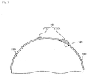
Fig. 1 is a schematic sectional view of a letterpress printing plate according to a first embodiment of the present invention; -
Fig. 2 is a schematic view illustrating printing using the letterpress printing plate according to the first embodiment of the present invention, and -
Fig. 3 is a schematic sectional view of a letterpress printing plate according to another embodiment of the present invention. - For the purposes of illustration, thicknesses of raised parts and buildup parts are shown exaggeratedly, relative to that of the letterpress printing plate.
- A
letterpress printing plate 100 according to an embodiment of the present invention is formed of photopolymer and processed using a photolithographic technique. The printing plate includes a main body, raisedparts 110 provided on a front face of the main body for applying printing ink thereon, and abuildup part 121 formed on a back face of the main body, more particularly, at a backside position of or in register with a raised part forsolid shade 111 of the raised parts with respect to the main body. - Raised
parts 110 ofletterpress printing plate 100 of such type are generally classified into a raised part forsolid shade 111 for printing a solid area, and the raised part forhalftone shade 112 for printing a halftone area. - As shown in
Fig. 1 , the raised part forsolid shade 111 generally projects in the form of a pedestal. The raised part forhalftone shade 112 consists of protruded portions to which printing ink adheres and recessed portions to which printing ink does not adhere. The protruded portions and the recessed portions are formed alternately depending on the halftone percentage as will be described later. - The printing plate of the embodiment is defined such that the main body is 0.44 mm in thickness while the raised part for
solid shade 111 and the raised part forhalftone shade 112 are each 0.7 mm in thickness. - The
buildup part 121 on the back side of theletterpress printing plate 100 is formed in a step after formation of theraised part 110 on the front side. Thebuildup part 121 is formed by a so-called inkjet printing machine. The thickness of thebuildup part 121 is determined such that, during a printing process, substantially the same pressure is applied to a portion (i.e., contact area) of the raised part forsolid shade 111 contacting the substrate and to a portion (i.e., contact area) of the raised part forhalftone shade 112 contacting the substrate. - More particularly, the thickness of the
buildup part 121 is increased by 5 µm for every ten percent difference between the halftone percentage of the raised part forhalftone shade 112 and that of the raised part forsolid shade 111. The halftone percentage of the raised part forsolid shade 111 is interpreted as 100%. - For example, where the halftone percentage of the raised part for
halftone shade 112 is 30%, the difference in halftone percentage between the raised part forhalftone shade 112 and the raised part forsolid shade 111 is 70%. Therefore, the thickness of thebuildup part 121 will be determined to be 35 µm. - The inkjet printing machine is fed, in advance, positional information of the raised
part 110 of theletterpress printing plate 100 for whichbuildup part 121 is to be formed. And this inkjet printing machine sprays ink onto only the area on the back side where the raised part forsolid shade 111 is present. As the ink dries, thebuildup part 121 is formed. As shown inFig. 2 , when theletterpress printing plate 100 with thebuildup part 121 formed is set on aroller 200 of a printing machine, the raised part forsolid shade 111 becomes higher than the raised part forhalftone shade 112 by the thickness of thebuildup part 121. As printing is conducted on a printing substrate in this condition, the raised part forsolid shade 111 has already become contacted with a printing substrate when the raised part forhalftone shade 112 comes into contact with the printing substrate. - In this manner, when an appropriate pressure is applied to the raised part for
halftone shade 112, a sufficient and appropriate pressure is applied also to the raised part forsolid shade 111, so that excellent printing quality is obtained for both the solid part and the halftone part. More particularly, the thickness of thebuildup part 121 functions to equalize the pressure per unit area applied to the contact area of the raised part forsolid shade 111 and the pressure applied to the contact area of the raised part forhalftone shade 112. - Additionally, since the inkjet printing machine previously stores positional information of the raised part for
solid shade 111, even when there is a region where the raised part forsolid shade 111 and the raised part forhalftone shade 112 are intricately mixed, ink is accurately sprayed only on the back side position of the part where the raised part forsolid shade 111 is formed. Therefore, thebuildup part 121 is accurately formed only at the back side position of the raised part forsolid shade 111. - In the aforementioned embodiment, the
buildup part 121 is formed only at the back side position of the raised part forsolid shade 111 with respect to the main body. In another embodiment to be described below, a buildup part is formed also at a back side position of a raised part for halftone shade with respect to the main body. - Generally speaking, halftone areas with different halftone percentages may be printed on a single printing substrate. "Halftone percentage" herein refers to a contact area contacting a printing substrate per unit area of a raised part for halftone shade. That is, a part having halftone percentage of 0 means that no printing is made on the part, and a part having halftone percentage of 100 is equivalent to a solid shade part.
- Assume that the same pressure per unit area, e.g., a pressure that is suited for halftone percentage of 50, is applied on a raised part for halftone shade having halftone percentage of 20 and on another raised part for halftone shade having halftone percentage of 80. In this case, the part of halftone percentage of 20 tends to be slightly squashed and the part of halftone percentage of 80 tends to be blurry because the pressure per contact area is higher for the part of halftone percentage of 20.
- In order to solve the problem, as shown in
Fig. 3 , the back face of the main body are provided with buildup parts forhalftone shade halftone shade - Particularly, the table shown below can be adopted to determine the respective thicknesses of the
buildup part 121, the buildup part forhalftone shade 122A, and the buildup part forhalftone shade 122B. It should be noted that the raised part forhalftone shade 112A, and the raised part forhalftone shade 112B are each 0.7 mm in thickness.Halftone percentage Thickness of the buildup part 10% 5 µm 20% 10 µm 30% 15 µm 40% 20 µm 50% 25 µm 60% 30 µm 70% 35 µm 80% 40 µm 90% 45 µm 100% (i.e. raised part for solid shade) 50 µm - As shown in the above table, at a back side position of the raised part for
halftone shade 112A having a higher halftone percentage, there is formed the buildup part forhalftone shade 122A with a larger thickness. This thickness is smaller than that of the buildup part (the buildup part for sold shade) 121 formed at the back side position of the raised part forsolid shade 111. On the other hand, at a back side position of the raised part forhalftone shade 112B having a lower halftone percentage, there is formed the buildup part forhalftone shade 122B with a smaller thickness than thebuildup part 122A. - As a result, halftone parts are appropriately printed regardless of the degree of halftone percentage.
- Also in this embodiment, the back face of the main body is provided with the buildup part for
solid shade 121 at the position corresponding to the raised part forsolid shade 111. The thickness of the buildup part forsolid shade 121 is larger than those of buildup parts forhalftone shade - Also in this embodiment, the
buildup parts solid shade 111 and raised parts for halftone shade 121A, 121B. Information entered into the inkjet printing machine includes not only the aforementioned positional information, but also information about halftone percentage of each of the raised parts forhalftone shade halftone shade - Although the above embodiment discloses a letterpress printing plate formed by a photolithographic technique as a representative of a letterpress printing plate, it goes without saying that the present invention will not be limited to this kind of printing plate. For example, a laser processing technique or other techniques may be used to form the buildup part for sold
shade 121 and the buildup part for halftone shade 122 (122A, 122B) on the back face of the main body. - Further, the printing plate may be of any type made of a material having flexibility such as one used for polymer letterpress printing or rubber plate printing, as well as flexography printing. Also, the values provided above for thicknesses of the main body, the buildup part and the buildup parts for halftone shade are exemplary only and are not to be construed as limiting values.
-
- 100
- LETTERPRESS PRINTING PLATE
- 110
- RAISED PART
- 111
- RAISED PART FOR SOLID SHADE
- 112
- RAISED PART FOR HALFTONE SHADE
- 121
- BUILDUP PART
Claims (4)
- A letterpress printing plate (100) made of a material having flexibility, comprising:a plurality of raised parts (110) for applying ink to, the raised parts including a raised part for solid shade (111);characterised by a buildup part (121) formed at a backside position of the raised part for solid shade (111) with respect to the printing plate.
- A letterpress printing plate (100) made of a material having flexibility, comprising:a plurality of raised parts (110) for applying ink to,the raised parts including a raised part (111) for solid shade and a raised part (112) for halftone shade;characterised by a plurality of buildup parts (121) formed at backside positions of the raised parts with respect to the printing plate, the buildup parts including:a buildup part for solid shade, being thickest of all the buildup parts and formed at the backside position of the raised part for solid shade; anda buildup part for halftone shade, being of a thickness smaller than the buildup part for solid shade, the thickness being set in accordance with a halftone percentage of the halftone.
- The letterpress printing plate (100) according to claim 1 or 2, which is formed by a photolithography technique.
- The letterpress printing plate (100) according to claim 1, 2 or 3, wherein said buildup part (121) or buildup parts (121) are formed of ink ejected by an inkjet printing machine.
Applications Claiming Priority (2)
| Application Number | Priority Date | Filing Date | Title |
|---|---|---|---|
| JP2007319631 | 2007-12-11 | ||
| JP2008018642A JP4410824B2 (en) | 2007-12-11 | 2008-01-30 | Letterpress printing plate |
Publications (3)
| Publication Number | Publication Date |
|---|---|
| EP2070715A2 EP2070715A2 (en) | 2009-06-17 |
| EP2070715A3 EP2070715A3 (en) | 2010-01-13 |
| EP2070715B1 true EP2070715B1 (en) | 2013-06-12 |
Family
ID=40427424
Family Applications (1)
| Application Number | Title | Priority Date | Filing Date |
|---|---|---|---|
| EP20080253692 Not-in-force EP2070715B1 (en) | 2007-12-11 | 2008-11-11 | Letterpress printing plate |
Country Status (3)
| Country | Link |
|---|---|
| US (1) | US8899149B2 (en) |
| EP (1) | EP2070715B1 (en) |
| CA (1) | CA2629661C (en) |
Family Cites Families (16)
| Publication number | Priority date | Publication date | Assignee | Title |
|---|---|---|---|---|
| GB8829802D0 (en) * | 1988-12-21 | 1989-02-15 | Prittie Allan R | Improved raised image plate construction |
| DE19642634A1 (en) * | 1996-10-16 | 1998-04-23 | Philips Patentverwaltung | Printing form for a rotary high-pressure process |
| JP3615887B2 (en) * | 1996-11-28 | 2005-02-02 | 理想科学工業株式会社 | Letterpress making method, letterpress making sheet, letterpress making apparatus and stamp making method |
| JPH1191229A (en) * | 1997-09-22 | 1999-04-06 | Mitsumura Printing Co Ltd | Pattern formation method |
| JP3705340B2 (en) * | 2000-04-10 | 2005-10-12 | 凸版印刷株式会社 | Thick film pattern forming letterpress, thick film pattern forming method using the same, and thick film pattern forming letterpress manufacturing method |
| JP2002019323A (en) | 2000-07-05 | 2002-01-23 | Toray Ind Inc | Laminates for flexographic printing |
| JP2002293049A (en) | 2001-03-29 | 2002-10-09 | Komuratekku:Kk | Resin letterpress for thin film formation |
| DE50104542D1 (en) | 2001-05-25 | 2004-12-23 | Stork Prints Austria Gmbh Lang | Process and device and for producing a printing form |
| JP3812723B2 (en) * | 2001-08-10 | 2006-08-23 | 小林記録紙株式会社 | Letterpress printing method |
| EP1428666B1 (en) | 2002-12-11 | 2007-04-25 | Agfa Graphics N.V. | Preparation of flexographic printing plates using ink jet recording |
| JP4467048B2 (en) | 2004-04-14 | 2010-05-26 | 旭化成イーマテリアルズ株式会社 | Method for producing flexographic printing plate |
| JP2005343051A (en) * | 2004-06-03 | 2005-12-15 | Oji Paper Co Ltd | Printing plate and printing method |
| JP2006175630A (en) * | 2004-12-21 | 2006-07-06 | Toppan Printing Co Ltd | Relief printing plate for relief reversal offset method, method for producing organic electroluminescence device using the same, and organic electroluminescence device |
| JP2006248065A (en) * | 2005-03-11 | 2006-09-21 | Toppan Printing Co Ltd | Ink supply substrate for letterpress printing, printing apparatus using the same, and printing method |
| JP2007185917A (en) | 2006-01-16 | 2007-07-26 | Asahi Kasei Chemicals Corp | Method for producing a printing plate for flexographic printing |
| JP5168805B2 (en) * | 2006-03-20 | 2013-03-27 | 凸版印刷株式会社 | Letterpress for letterpress reversal offset printing and method for producing the same, or printed matter production method using the same |
-
2008
- 2008-04-24 CA CA2629661A patent/CA2629661C/en not_active Expired - Fee Related
- 2008-05-27 US US12/153,866 patent/US8899149B2/en not_active Expired - Fee Related
- 2008-11-11 EP EP20080253692 patent/EP2070715B1/en not_active Not-in-force
Also Published As
| Publication number | Publication date |
|---|---|
| EP2070715A2 (en) | 2009-06-17 |
| CA2629661A1 (en) | 2009-06-11 |
| US20090145316A1 (en) | 2009-06-11 |
| CA2629661C (en) | 2015-01-06 |
| US8899149B2 (en) | 2014-12-02 |
| EP2070715A3 (en) | 2010-01-13 |
Similar Documents
| Publication | Publication Date | Title |
|---|---|---|
| JP3689536B2 (en) | Image forming method | |
| EP3007901B1 (en) | Printing process using soft photopolymer plates | |
| US10850497B2 (en) | Apparatus and method for forming high definition lithographic images on containers | |
| US6648470B2 (en) | Apparatus and method for printing | |
| JP4648301B2 (en) | Blanket cylinder of intaglio printing machine | |
| CA2019046A1 (en) | Method of printing fine patterns | |
| EP3283296B1 (en) | Variable printing process using flexible secondary plates and specialty inks | |
| JP2006516492A5 (en) | ||
| US20060112844A1 (en) | Method for producing flexoprinting forms by means of laser engraving using photopolymer flexoprinting elements and photopolymerisable flexoprinting element | |
| US10857779B2 (en) | Three dimensional pattern printing device and method for manufacturing micro-optical film structure by using same | |
| CN101321625B (en) | Systems and methods for mounting printing plates to bonded members | |
| CA2204821C (en) | Surface for the transfer of a more or less viscous liquid product upon a support, method of manufacturing such a surface and offset printing blanket provided with this surface | |
| EP2070715A2 (en) | Letterpress printing plate | |
| CN101456309B (en) | Letterpress printing plate | |
| US6766741B1 (en) | Inking plate for rotary printing machine | |
| JP2003053927A (en) | Letterpress printing method | |
| US5303646A (en) | Relief printing method and apparatus for its implementation | |
| JP3606286B2 (en) | Topographic printing device | |
| HK1131103B (en) | Letterpress printing plate | |
| JP2789461B2 (en) | Method of forming printing surface of printing blanket | |
| US20040094055A1 (en) | Gravure sleeve | |
| JP2005014410A (en) | How to prevent damage to the blanket of an offset printing press | |
| JPH07256854A (en) | Damping water unnecessary planographic intaglio and offset printing method using the same | |
| JP2002361752A (en) | Double side processing equipment | |
| JP2008540171A (en) | blanket |
Legal Events
| Date | Code | Title | Description |
|---|---|---|---|
| PUAI | Public reference made under article 153(3) epc to a published international application that has entered the european phase |
Free format text: ORIGINAL CODE: 0009012 |
|
| AK | Designated contracting states |
Kind code of ref document: A2 Designated state(s): AT BE BG CH CY CZ DE DK EE ES FI FR GB GR HR HU IE IS IT LI LT LU LV MC MT NL NO PL PT RO SE SI SK TR |
|
| AX | Request for extension of the european patent |
Extension state: AL BA MK RS |
|
| PUAL | Search report despatched |
Free format text: ORIGINAL CODE: 0009013 |
|
| AK | Designated contracting states |
Kind code of ref document: A3 Designated state(s): AT BE BG CH CY CZ DE DK EE ES FI FR GB GR HR HU IE IS IT LI LT LU LV MC MT NL NO PL PT RO SE SI SK TR |
|
| AX | Request for extension of the european patent |
Extension state: AL BA MK RS |
|
| RIC1 | Information provided on ipc code assigned before grant |
Ipc: B41M 1/02 20060101ALI20091209BHEP Ipc: B41N 1/06 20060101AFI20090325BHEP Ipc: B41C 1/00 20060101ALN20090325BHEP |
|
| 17P | Request for examination filed |
Effective date: 20100629 |
|
| AKX | Designation fees paid |
Designated state(s): AT BE BG CH CY CZ DE DK EE ES FI FR GB GR HR HU IE IS IT LI LT LU LV MC MT NL NO PL PT RO SE SI SK TR |
|
| REG | Reference to a national code |
Ref country code: DE Ref legal event code: R079 Ref document number: 602008025262 Country of ref document: DE Free format text: PREVIOUS MAIN CLASS: B41N0001060000 Ipc: B41N0001120000 |
|
| RIC1 | Information provided on ipc code assigned before grant |
Ipc: B41C 1/00 20060101ALN20121022BHEP Ipc: B41N 1/12 20060101AFI20121022BHEP |
|
| GRAP | Despatch of communication of intention to grant a patent |
Free format text: ORIGINAL CODE: EPIDOSNIGR1 |
|
| GRAS | Grant fee paid |
Free format text: ORIGINAL CODE: EPIDOSNIGR3 |
|
| GRAA | (expected) grant |
Free format text: ORIGINAL CODE: 0009210 |
|
| AK | Designated contracting states |
Kind code of ref document: B1 Designated state(s): AT BE BG CH CY CZ DE DK EE ES FI FR GB GR HR HU IE IS IT LI LT LU LV MC MT NL NO PL PT RO SE SI SK TR |
|
| REG | Reference to a national code |
Ref country code: GB Ref legal event code: FG4D |
|
| REG | Reference to a national code |
Ref country code: CH Ref legal event code: EP |
|
| REG | Reference to a national code |
Ref country code: AT Ref legal event code: REF Ref document number: 616527 Country of ref document: AT Kind code of ref document: T Effective date: 20130615 |
|
| REG | Reference to a national code |
Ref country code: IE Ref legal event code: FG4D |
|
| REG | Reference to a national code |
Ref country code: DE Ref legal event code: R096 Ref document number: 602008025262 Country of ref document: DE Effective date: 20130808 |
|
| PG25 | Lapsed in a contracting state [announced via postgrant information from national office to epo] |
Ref country code: FI Free format text: LAPSE BECAUSE OF FAILURE TO SUBMIT A TRANSLATION OF THE DESCRIPTION OR TO PAY THE FEE WITHIN THE PRESCRIBED TIME-LIMIT Effective date: 20130612 Ref country code: NO Free format text: LAPSE BECAUSE OF FAILURE TO SUBMIT A TRANSLATION OF THE DESCRIPTION OR TO PAY THE FEE WITHIN THE PRESCRIBED TIME-LIMIT Effective date: 20130912 Ref country code: GR Free format text: LAPSE BECAUSE OF FAILURE TO SUBMIT A TRANSLATION OF THE DESCRIPTION OR TO PAY THE FEE WITHIN THE PRESCRIBED TIME-LIMIT Effective date: 20130913 Ref country code: ES Free format text: LAPSE BECAUSE OF FAILURE TO SUBMIT A TRANSLATION OF THE DESCRIPTION OR TO PAY THE FEE WITHIN THE PRESCRIBED TIME-LIMIT Effective date: 20130923 Ref country code: SE Free format text: LAPSE BECAUSE OF FAILURE TO SUBMIT A TRANSLATION OF THE DESCRIPTION OR TO PAY THE FEE WITHIN THE PRESCRIBED TIME-LIMIT Effective date: 20130612 Ref country code: SI Free format text: LAPSE BECAUSE OF FAILURE TO SUBMIT A TRANSLATION OF THE DESCRIPTION OR TO PAY THE FEE WITHIN THE PRESCRIBED TIME-LIMIT Effective date: 20130612 Ref country code: LT Free format text: LAPSE BECAUSE OF FAILURE TO SUBMIT A TRANSLATION OF THE DESCRIPTION OR TO PAY THE FEE WITHIN THE PRESCRIBED TIME-LIMIT Effective date: 20130612 |
|
| REG | Reference to a national code |
Ref country code: AT Ref legal event code: MK05 Ref document number: 616527 Country of ref document: AT Kind code of ref document: T Effective date: 20130612 |
|
| REG | Reference to a national code |
Ref country code: NL Ref legal event code: VDEP Effective date: 20130612 |
|
| REG | Reference to a national code |
Ref country code: LT Ref legal event code: MG4D |
|
| PG25 | Lapsed in a contracting state [announced via postgrant information from national office to epo] |
Ref country code: HR Free format text: LAPSE BECAUSE OF FAILURE TO SUBMIT A TRANSLATION OF THE DESCRIPTION OR TO PAY THE FEE WITHIN THE PRESCRIBED TIME-LIMIT Effective date: 20130612 Ref country code: BG Free format text: LAPSE BECAUSE OF FAILURE TO SUBMIT A TRANSLATION OF THE DESCRIPTION OR TO PAY THE FEE WITHIN THE PRESCRIBED TIME-LIMIT Effective date: 20130912 |
|
| PG25 | Lapsed in a contracting state [announced via postgrant information from national office to epo] |
Ref country code: LV Free format text: LAPSE BECAUSE OF FAILURE TO SUBMIT A TRANSLATION OF THE DESCRIPTION OR TO PAY THE FEE WITHIN THE PRESCRIBED TIME-LIMIT Effective date: 20130612 |
|
| PG25 | Lapsed in a contracting state [announced via postgrant information from national office to epo] |
Ref country code: CZ Free format text: LAPSE BECAUSE OF FAILURE TO SUBMIT A TRANSLATION OF THE DESCRIPTION OR TO PAY THE FEE WITHIN THE PRESCRIBED TIME-LIMIT Effective date: 20130612 Ref country code: BE Free format text: LAPSE BECAUSE OF FAILURE TO SUBMIT A TRANSLATION OF THE DESCRIPTION OR TO PAY THE FEE WITHIN THE PRESCRIBED TIME-LIMIT Effective date: 20130612 Ref country code: AT Free format text: LAPSE BECAUSE OF FAILURE TO SUBMIT A TRANSLATION OF THE DESCRIPTION OR TO PAY THE FEE WITHIN THE PRESCRIBED TIME-LIMIT Effective date: 20130612 Ref country code: PT Free format text: LAPSE BECAUSE OF FAILURE TO SUBMIT A TRANSLATION OF THE DESCRIPTION OR TO PAY THE FEE WITHIN THE PRESCRIBED TIME-LIMIT Effective date: 20131014 Ref country code: IS Free format text: LAPSE BECAUSE OF FAILURE TO SUBMIT A TRANSLATION OF THE DESCRIPTION OR TO PAY THE FEE WITHIN THE PRESCRIBED TIME-LIMIT Effective date: 20131012 Ref country code: EE Free format text: LAPSE BECAUSE OF FAILURE TO SUBMIT A TRANSLATION OF THE DESCRIPTION OR TO PAY THE FEE WITHIN THE PRESCRIBED TIME-LIMIT Effective date: 20130612 Ref country code: SK Free format text: LAPSE BECAUSE OF FAILURE TO SUBMIT A TRANSLATION OF THE DESCRIPTION OR TO PAY THE FEE WITHIN THE PRESCRIBED TIME-LIMIT Effective date: 20130612 |
|
| PG25 | Lapsed in a contracting state [announced via postgrant information from national office to epo] |
Ref country code: RO Free format text: LAPSE BECAUSE OF FAILURE TO SUBMIT A TRANSLATION OF THE DESCRIPTION OR TO PAY THE FEE WITHIN THE PRESCRIBED TIME-LIMIT Effective date: 20130612 Ref country code: NL Free format text: LAPSE BECAUSE OF FAILURE TO SUBMIT A TRANSLATION OF THE DESCRIPTION OR TO PAY THE FEE WITHIN THE PRESCRIBED TIME-LIMIT Effective date: 20130612 Ref country code: PL Free format text: LAPSE BECAUSE OF FAILURE TO SUBMIT A TRANSLATION OF THE DESCRIPTION OR TO PAY THE FEE WITHIN THE PRESCRIBED TIME-LIMIT Effective date: 20130612 |
|
| PLBE | No opposition filed within time limit |
Free format text: ORIGINAL CODE: 0009261 |
|
| STAA | Information on the status of an ep patent application or granted ep patent |
Free format text: STATUS: NO OPPOSITION FILED WITHIN TIME LIMIT |
|
| PG25 | Lapsed in a contracting state [announced via postgrant information from national office to epo] |
Ref country code: DK Free format text: LAPSE BECAUSE OF FAILURE TO SUBMIT A TRANSLATION OF THE DESCRIPTION OR TO PAY THE FEE WITHIN THE PRESCRIBED TIME-LIMIT Effective date: 20130612 |
|
| 26N | No opposition filed |
Effective date: 20140313 |
|
| PG25 | Lapsed in a contracting state [announced via postgrant information from national office to epo] |
Ref country code: IT Free format text: LAPSE BECAUSE OF FAILURE TO SUBMIT A TRANSLATION OF THE DESCRIPTION OR TO PAY THE FEE WITHIN THE PRESCRIBED TIME-LIMIT Effective date: 20130612 |
|
| REG | Reference to a national code |
Ref country code: DE Ref legal event code: R097 Ref document number: 602008025262 Country of ref document: DE Effective date: 20140313 |
|
| REG | Reference to a national code |
Ref country code: CH Ref legal event code: PL |
|
| PG25 | Lapsed in a contracting state [announced via postgrant information from national office to epo] |
Ref country code: CH Free format text: LAPSE BECAUSE OF NON-PAYMENT OF DUE FEES Effective date: 20131130 Ref country code: MC Free format text: LAPSE BECAUSE OF FAILURE TO SUBMIT A TRANSLATION OF THE DESCRIPTION OR TO PAY THE FEE WITHIN THE PRESCRIBED TIME-LIMIT Effective date: 20130612 Ref country code: LI Free format text: LAPSE BECAUSE OF NON-PAYMENT OF DUE FEES Effective date: 20131130 |
|
| REG | Reference to a national code |
Ref country code: IE Ref legal event code: MM4A |
|
| PG25 | Lapsed in a contracting state [announced via postgrant information from national office to epo] |
Ref country code: IE Free format text: LAPSE BECAUSE OF NON-PAYMENT OF DUE FEES Effective date: 20131111 |
|
| PG25 | Lapsed in a contracting state [announced via postgrant information from national office to epo] |
Ref country code: CY Free format text: LAPSE BECAUSE OF FAILURE TO SUBMIT A TRANSLATION OF THE DESCRIPTION OR TO PAY THE FEE WITHIN THE PRESCRIBED TIME-LIMIT Effective date: 20130612 Ref country code: TR Free format text: LAPSE BECAUSE OF FAILURE TO SUBMIT A TRANSLATION OF THE DESCRIPTION OR TO PAY THE FEE WITHIN THE PRESCRIBED TIME-LIMIT Effective date: 20130612 |
|
| PG25 | Lapsed in a contracting state [announced via postgrant information from national office to epo] |
Ref country code: HU Free format text: LAPSE BECAUSE OF FAILURE TO SUBMIT A TRANSLATION OF THE DESCRIPTION OR TO PAY THE FEE WITHIN THE PRESCRIBED TIME-LIMIT; INVALID AB INITIO Effective date: 20081111 Ref country code: LU Free format text: LAPSE BECAUSE OF NON-PAYMENT OF DUE FEES Effective date: 20131111 |
|
| PG25 | Lapsed in a contracting state [announced via postgrant information from national office to epo] |
Ref country code: MT Free format text: LAPSE BECAUSE OF FAILURE TO SUBMIT A TRANSLATION OF THE DESCRIPTION OR TO PAY THE FEE WITHIN THE PRESCRIBED TIME-LIMIT Effective date: 20130612 |
|
| REG | Reference to a national code |
Ref country code: FR Ref legal event code: PLFP Year of fee payment: 8 |
|
| REG | Reference to a national code |
Ref country code: FR Ref legal event code: PLFP Year of fee payment: 9 |
|
| REG | Reference to a national code |
Ref country code: FR Ref legal event code: PLFP Year of fee payment: 10 |
|
| REG | Reference to a national code |
Ref country code: FR Ref legal event code: PLFP Year of fee payment: 11 |
|
| PGFP | Annual fee paid to national office [announced via postgrant information from national office to epo] |
Ref country code: FR Payment date: 20210930 Year of fee payment: 14 |
|
| PGFP | Annual fee paid to national office [announced via postgrant information from national office to epo] |
Ref country code: GB Payment date: 20210922 Year of fee payment: 14 |
|
| PGFP | Annual fee paid to national office [announced via postgrant information from national office to epo] |
Ref country code: DE Payment date: 20210923 Year of fee payment: 14 |
|
| REG | Reference to a national code |
Ref country code: DE Ref legal event code: R119 Ref document number: 602008025262 Country of ref document: DE |
|
| GBPC | Gb: european patent ceased through non-payment of renewal fee |
Effective date: 20221111 |
|
| PG25 | Lapsed in a contracting state [announced via postgrant information from national office to epo] |
Ref country code: GB Free format text: LAPSE BECAUSE OF NON-PAYMENT OF DUE FEES Effective date: 20221111 Ref country code: DE Free format text: LAPSE BECAUSE OF NON-PAYMENT OF DUE FEES Effective date: 20230601 |
|
| PG25 | Lapsed in a contracting state [announced via postgrant information from national office to epo] |
Ref country code: FR Free format text: LAPSE BECAUSE OF NON-PAYMENT OF DUE FEES Effective date: 20221130 |