EP2069679B1 - Klebeband zur abdichtung einer verbindung in einem isolationssystem und verfahren zur abdichtung einer solchen verbindung - Google Patents
Klebeband zur abdichtung einer verbindung in einem isolationssystem und verfahren zur abdichtung einer solchen verbindung Download PDFInfo
- Publication number
- EP2069679B1 EP2069679B1 EP07835049.3A EP07835049A EP2069679B1 EP 2069679 B1 EP2069679 B1 EP 2069679B1 EP 07835049 A EP07835049 A EP 07835049A EP 2069679 B1 EP2069679 B1 EP 2069679B1
- Authority
- EP
- European Patent Office
- Prior art keywords
- adhesive tape
- hygroscopic material
- joint
- layer
- insulation system
- Prior art date
- Legal status (The legal status is an assumption and is not a legal conclusion. Google has not performed a legal analysis and makes no representation as to the accuracy of the status listed.)
- Active
Links
- 239000002390 adhesive tape Substances 0.000 title claims description 112
- 238000009413 insulation Methods 0.000 title claims description 53
- 238000007789 sealing Methods 0.000 title claims description 16
- 238000000034 method Methods 0.000 title claims description 9
- 239000000463 material Substances 0.000 claims description 110
- 230000004888 barrier function Effects 0.000 claims description 42
- 239000012080 ambient air Substances 0.000 claims description 19
- 230000008020 evaporation Effects 0.000 claims description 17
- 238000001704 evaporation Methods 0.000 claims description 17
- 239000000853 adhesive Substances 0.000 claims description 9
- 230000001070 adhesive effect Effects 0.000 claims description 9
- 239000010410 layer Substances 0.000 description 47
- 239000011230 binding agent Substances 0.000 description 12
- XLYOFNOQVPJJNP-UHFFFAOYSA-N water Substances O XLYOFNOQVPJJNP-UHFFFAOYSA-N 0.000 description 9
- 239000011810 insulating material Substances 0.000 description 8
- 230000001681 protective effect Effects 0.000 description 7
- 238000009792 diffusion process Methods 0.000 description 6
- 239000004033 plastic Substances 0.000 description 6
- 229920003023 plastic Polymers 0.000 description 6
- 239000011888 foil Substances 0.000 description 5
- 239000002184 metal Substances 0.000 description 4
- 229910052751 metal Inorganic materials 0.000 description 4
- 239000002344 surface layer Substances 0.000 description 4
- 238000010521 absorption reaction Methods 0.000 description 3
- 238000009434 installation Methods 0.000 description 3
- 230000010354 integration Effects 0.000 description 3
- 238000004519 manufacturing process Methods 0.000 description 3
- 239000000123 paper Substances 0.000 description 3
- 239000004698 Polyethylene Substances 0.000 description 2
- 239000005030 aluminium foil Substances 0.000 description 2
- 230000008901 benefit Effects 0.000 description 2
- 230000007547 defect Effects 0.000 description 2
- 230000001627 detrimental effect Effects 0.000 description 2
- 239000003365 glass fiber Substances 0.000 description 2
- 229920000573 polyethylene Polymers 0.000 description 2
- 239000011148 porous material Substances 0.000 description 2
- 229920001169 thermoplastic Polymers 0.000 description 2
- 239000012815 thermoplastic material Substances 0.000 description 2
- 239000004416 thermosoftening plastic Substances 0.000 description 2
- 238000009423 ventilation Methods 0.000 description 2
- 239000005995 Aluminium silicate Substances 0.000 description 1
- 239000004677 Nylon Substances 0.000 description 1
- VYPSYNLAJGMNEJ-UHFFFAOYSA-N Silicium dioxide Chemical compound O=[Si]=O VYPSYNLAJGMNEJ-UHFFFAOYSA-N 0.000 description 1
- 230000009471 action Effects 0.000 description 1
- PZZYQPZGQPZBDN-UHFFFAOYSA-N aluminium silicate Chemical compound O=[Al]O[Si](=O)O[Al]=O PZZYQPZGQPZBDN-UHFFFAOYSA-N 0.000 description 1
- 229910000323 aluminium silicate Inorganic materials 0.000 description 1
- 235000012211 aluminium silicate Nutrition 0.000 description 1
- 239000011111 cardboard Substances 0.000 description 1
- 238000005266 casting Methods 0.000 description 1
- 239000004927 clay Substances 0.000 description 1
- 229910052570 clay Inorganic materials 0.000 description 1
- 238000004891 communication Methods 0.000 description 1
- 230000000295 complement effect Effects 0.000 description 1
- 230000008094 contradictory effect Effects 0.000 description 1
- 230000007797 corrosion Effects 0.000 description 1
- 238000005260 corrosion Methods 0.000 description 1
- 230000000694 effects Effects 0.000 description 1
- 238000005516 engineering process Methods 0.000 description 1
- 238000005470 impregnation Methods 0.000 description 1
- 230000001788 irregular Effects 0.000 description 1
- 230000008018 melting Effects 0.000 description 1
- 238000002844 melting Methods 0.000 description 1
- 230000005012 migration Effects 0.000 description 1
- 238000013508 migration Methods 0.000 description 1
- 239000011490 mineral wool Substances 0.000 description 1
- 239000000203 mixture Substances 0.000 description 1
- 229920001778 nylon Polymers 0.000 description 1
- 239000003973 paint Substances 0.000 description 1
- 230000000149 penetrating effect Effects 0.000 description 1
- 230000035515 penetration Effects 0.000 description 1
- 229920000728 polyester Polymers 0.000 description 1
- -1 polyethylene Polymers 0.000 description 1
- 229920001296 polysiloxane Polymers 0.000 description 1
- 230000008569 process Effects 0.000 description 1
- 230000002787 reinforcement Effects 0.000 description 1
- 239000000741 silica gel Substances 0.000 description 1
- 229910002027 silica gel Inorganic materials 0.000 description 1
- 230000007480 spreading Effects 0.000 description 1
- 238000003892 spreading Methods 0.000 description 1
- 239000000126 substance Substances 0.000 description 1
- 239000013589 supplement Substances 0.000 description 1
- 230000032258 transport Effects 0.000 description 1
- 239000002023 wood Substances 0.000 description 1
Images


Classifications
-
- F—MECHANICAL ENGINEERING; LIGHTING; HEATING; WEAPONS; BLASTING
- F16—ENGINEERING ELEMENTS AND UNITS; GENERAL MEASURES FOR PRODUCING AND MAINTAINING EFFECTIVE FUNCTIONING OF MACHINES OR INSTALLATIONS; THERMAL INSULATION IN GENERAL
- F16L—PIPES; JOINTS OR FITTINGS FOR PIPES; SUPPORTS FOR PIPES, CABLES OR PROTECTIVE TUBING; MEANS FOR THERMAL INSULATION IN GENERAL
- F16L59/00—Thermal insulation in general
- F16L59/02—Shape or form of insulating materials, with or without coverings integral with the insulating materials
- F16L59/021—Shape or form of insulating materials, with or without coverings integral with the insulating materials comprising a single piece or sleeve, e.g. split sleeve, two half sleeves
-
- F—MECHANICAL ENGINEERING; LIGHTING; HEATING; WEAPONS; BLASTING
- F16—ENGINEERING ELEMENTS AND UNITS; GENERAL MEASURES FOR PRODUCING AND MAINTAINING EFFECTIVE FUNCTIONING OF MACHINES OR INSTALLATIONS; THERMAL INSULATION IN GENERAL
- F16L—PIPES; JOINTS OR FITTINGS FOR PIPES; SUPPORTS FOR PIPES, CABLES OR PROTECTIVE TUBING; MEANS FOR THERMAL INSULATION IN GENERAL
- F16L59/00—Thermal insulation in general
- F16L59/02—Shape or form of insulating materials, with or without coverings integral with the insulating materials
- F16L59/028—Composition or method of fixing a thermally insulating material
-
- F—MECHANICAL ENGINEERING; LIGHTING; HEATING; WEAPONS; BLASTING
- F16—ENGINEERING ELEMENTS AND UNITS; GENERAL MEASURES FOR PRODUCING AND MAINTAINING EFFECTIVE FUNCTIONING OF MACHINES OR INSTALLATIONS; THERMAL INSULATION IN GENERAL
- F16L—PIPES; JOINTS OR FITTINGS FOR PIPES; SUPPORTS FOR PIPES, CABLES OR PROTECTIVE TUBING; MEANS FOR THERMAL INSULATION IN GENERAL
- F16L59/00—Thermal insulation in general
- F16L59/10—Bandages or covers for the protection of the insulation, e.g. against the influence of the environment or against mechanical damage
-
- F—MECHANICAL ENGINEERING; LIGHTING; HEATING; WEAPONS; BLASTING
- F16—ENGINEERING ELEMENTS AND UNITS; GENERAL MEASURES FOR PRODUCING AND MAINTAINING EFFECTIVE FUNCTIONING OF MACHINES OR INSTALLATIONS; THERMAL INSULATION IN GENERAL
- F16L—PIPES; JOINTS OR FITTINGS FOR PIPES; SUPPORTS FOR PIPES, CABLES OR PROTECTIVE TUBING; MEANS FOR THERMAL INSULATION IN GENERAL
- F16L59/00—Thermal insulation in general
- F16L59/14—Arrangements for the insulation of pipes or pipe systems
-
- B—PERFORMING OPERATIONS; TRANSPORTING
- B32—LAYERED PRODUCTS
- B32B—LAYERED PRODUCTS, i.e. PRODUCTS BUILT-UP OF STRATA OF FLAT OR NON-FLAT, e.g. CELLULAR OR HONEYCOMB, FORM
- B32B2307/00—Properties of the layers or laminate
- B32B2307/70—Other properties
- B32B2307/728—Hydrophilic
Definitions
- the present invention relates to an adhesive tape for sealing a joint in an insulation system, and a method for sealing a joint in an insulation system.
- a typical insulation consists of a thermally insulating material, such as mineral wool, which on its side facing the ambient air has a protective surface layer of plastic, paper or metal.
- a first example is given by US 5,441,083 .
- This solution uses layers of a hygroscopic material on both sides of a thermally insulating material which is adapted to be arranged around, for instance, a pipe. The two layers are in contact with each other.
- the inner layer is arranged to surround the pipe and, with its respective free ends, protrude through the slot of the pipe shell to such an extent that its ends can be arranged against the outside of the pipe shell where they are exposed to the ambient air and form an evaporation surface.
- US 5 690 147 A discloses a heat-insulating assembly for insulating a surface of a tubular body relative to the ambient air.
- thermally insulating layer of the insulation system is provided with an outer laminate which comprises a vapour barrier and, connected thereto, a layer of a hygroscopic material.
- the object of the present invention is to provide an improved adhesive tape for sealing joints in insulation systems.
- the adhesive tape should be easy to apply and not have a detrimental effect on a possibly existing or integrated hygroscopic material in an insulation system.
- the adhesive tape should in itself be able to replace or at least supplement the use of hygroscopic material in an insulation system.
- the adhesive tape should also be easy to mount, without necessitating experience from mounting of prior art systems.
- the present invention concerns an adhesive tape for sealing a joint in an insulation system according to claim 1, and also a method for sealing such joints according to claim 13.
- vapour barrier relates to a material which makes vapour diffusion and vapour convection difficult.
- hygroscopic material relates to a material which absorbs and transports water vapour and condensate and which emits water vapour due to the moisture of the ambient air in such a manner that equilibrium is achieved.
- the invention relates to an adhesive tape for sealing a joint in an insulation system, comprising a first layer which forms a vapour barrier and is adapted to form an outside of the adhesive tape, a hygroscopic material which is supported by the first layer and, when applying the adhesive tape for sealing a joint in an insulation system, is adapted to be in contact with the joint, and at least one adhesive connecting portion which is arranged on an inside of the adhesive tape and which, when applying the adhesive tape, is adapted to adhere to the insulation system on at least one side of the joint.
- an adhesive tape which allows absorption of condensate and moisture from the inside of the insulation system while at the same time it allows evaporation to the ambient air in a direction perpendicular to the direction of extension/plane of extension of the adhesive tape by moisture and condensate migration which occurs in the thickness direction of the adhesive tape.
- evaporation may also occur along the edge portions of the adhesive tape, that is in a direction that coincides with the direction of extension/plane of extension of the adhesive tape. In the latter case, the cross-sectional surface of the hygroscopic material forms an evaporation surface.
- the adhesive tape can replace the use of loose hygroscopic material, but also use of insulation systems with integrated hygroscopic material.
- the adhesive tape may be applied to insulation systems with integrated hygroscopic material without having a detrimental effect on evaporation.
- the adhesive tape is very easy to mount regardless of the form of the insulation system.
- the adhesive tape comprises more than one adhesive connecting portion, these can be arranged to adhere to the insulation system on both sides of the joint. If the adhesive tape adheres to the outside of the insulation system on both sides of a hygroscopic material arranged in the insulation system, the hygroscopic material of the adhesive tape will be in contact with the same and allow absorption and evaporation through the first vapour barrier forming layer of the adhesive tape.
- the hygroscopic material may form a second layer, which second layer is supported by the first layer.
- a second layer can be a continuous or a partially continuous structure.
- the hygroscopic material may be integrated with the first layer. Integration can be provided by, for example, casting, interweaving, melting or by using a binder. Integration should be arranged so that the hygroscopic material at least partially can make contact with the insulation system. The integration results in a form of reinforcement which increases the tear strength of the vapour barrier and, thus, the risk of outer damage to the adhesive tape.
- the hygroscopic material can on the one hand be integrated with the first layer and, on the other hand, form a second layer supported by the vapour barrier, the second layer being in contact with the hygroscopic material in the first layer.
- the hygroscopic material may have different structures or alternatively textures depending on where in the adhesive tape it is arranged.
- the hygroscopic material integrated with the first layer may, for example, have a non-continuous structure while the layer supported by the vapour barrier may, for example, have a continuous structure with a textured surface.
- the hygroscopic material may at least partially have a non-continuous structure.
- a non-continuous structure is a net-like structure.
- the hygroscopic material may extend over an entire surface facing away from the outside of the first layer.
- the hygroscopic material When applying the adhesive tape, the hygroscopic material may be insertable into said joint in the insulation system. As a result, the hygroscopic material may be put in direct contact with the interior of the insulation system and even with the element exposed to condensate.
- the hygroscopic material may have a free end which projects from the first layer and which, when applying the adhesive tape, is insertable into said joint in the insulation system.
- the hygroscopic material between said connecting portions may form a loop, which loop, when applying the adhesive tape, is insertable into said joint in the insulation system.
- the first layer may have perforations via which the hygroscopic material is in contact with the ambient air.
- the perforations put the hygroscopic material in contact with the ambient air, whereby the condensate absorbed from the insulated surface and the thermally insulating material may evaporate.
- the hygroscopic material may have evaporation surfaces arranged in the thickness direction of the adhesive tape, via which evaporation surfaces the hygroscopic material is in contact with the ambient air. These evaporation surfaces suitably consist of the cross-sectional surface of the hygroscopic material seen in its thickness direction.
- the invention relates to a method of sealing a joint in an insulation system, comprising applying over said joint an adhesive tape having a vapour barrier forming an outside and a hygroscopic material supported by the vapour barrier, in such a manner that said hygroscopic material is put in contact with the joint and so that the adhesive tape adheres to the insulation system on at least one side of said joint.
- the method may comprise the step of inserting at least parts of the hygroscopic material supported by the vapour barrier into said joint.
- the inventive adhesive tape is adapted to seal a joint in an insulation system, which is adapted to be used for pipes, containers, ventilation ducts and like installation parts which periodically have an outer temperature which is below the dew point of the ambient air.
- an insulation system which is adapted to be used for pipes, containers, ventilation ducts and like installation parts which periodically have an outer temperature which is below the dew point of the ambient air.
- element will be used for these pipes, containers, ventilation ducts or installation parts.
- installation system concerns thermal insulation of said elements, which insulation may have a number of different geometric shapes, such as sheets, mats or shells.
- a first embodiment of the inventive adhesive tape 1 is shown. It should be emphasised that all the material layers in Fig. 1 and the other figures are, for the sake of clarity, shown with highly exaggerated proportions.
- the adhesive tape 1 comprises, starting from the outside, a vapour barrier 2, a hygroscopic material 3, a layer with two adhesive connecting portions 4 and a protective film 5 arranged on the connecting portions.
- the layers will be described individually below.
- the vapour barrier 2 which forms the outside of the adhesive tape 1 makes vapour diffusion or vapour convection difficult.
- the vapour barrier 2 can be made of various materials, where the choice of material is a matter of, inter alia, the environment in which the insulation system is to act, current specified building standards, current fire control standards and, above all, costs. Examples of suitable materials are metal foil, plastic foil, paper with or without impregnation or laminates thereof.
- the vapour barrier 2 supports a layer of a hygroscopic material 3.
- the hygroscopic material 3 is preferably connected to the vapour barrier 2 by some kind of binder layer 6.
- the binder 6, which suitably is thermoplastic, may consist of a number of different substances, polyethylene (PE) being the most preferred one.
- the binder layer 6 should have such a thickness that the hygroscopic material 3 at least partially, and preferably along the major part of its surface which faces away from the vapour barrier 2, is free of binder 6.
- the hygroscopic material 3 may consist of a number of different materials, such as glass fibre, wood, cardboard, activated clay, aluminium silicate or silica gel.
- the hygroscopic material 3 may also consist of a thermoplastic material such as polyester or nylon. The latter type of material means that the amount of thermoplastic binder can be reduced or excluded completely since the vapour barrier 2 and the hygroscopic material 3 can be made to bond to each other to form a laminate in the manufacture of the adhesive tape.
- the hygroscopic material 3 consists of glass fibre or a thermoplastic material, it is preferred if the hygroscopic material 3 has the form of a compressed, woven, nonwoven, spun, pleated or knitted structure.
- the hygroscopic material 3 may also consist of a hygroscopic paint.
- the hygroscopic material 3 has a compressed, continuous structure.
- the structure of the hygroscopic material 3 illustrated in Fig. 1 is only one conceivable embodiment.
- the vapour barrier 2 preferably comprises perforations 7 (schematically illustrated).
- the perforations 7 are arranged through the vapour barrier 2 in such a manner that they put the hygroscopic material 3 in contact with the ambient air, thereby allowing the condensate absorbed to evaporate.
- the perforations 7 have such a depth that they penetrate the vapour barrier 2 and an optional binder layer 6 between the vapour barrier 2 and the hygroscopic material 3.
- the perforations 7 are preferably arranged with a frequency of 30-100 000 perforations/m 2 , more preferred 200-50 000 perforations/m 2 and most preferred 1 000-30 000 perforations/m 2 .
- the perforations 7 can be arranged in a regular or irregular pattern.
- perforations 7 By the perforations 7 being arranged over the surface of the vapour barrier 2, perforations will, independently of the design and structure of the hygroscopic material 3, directly coincide with the hygroscopic material and thus form an opening for communication with the ambient air.
- the above described perforations 7 may be excluded.
- the vapour barrier 2 consists of a metal or plastic foil, it contains, due to its manufacturing process, a varying degree of pinholes, which facilitate diffusion.
- pin holes is meant defects in the material that appear as small microperforations. The thinner the foil, the more pin holes.
- the lower value 200 in the range 200-50 000 perforations/m 2 corresponds to the number of pin holes that arise in normal manufacture of an aluminium foil with a thickness of 7 ⁇ m. Pin holes have been found to give the surprising effect that they allow sufficient evaporation of condensate from the hygroscopic material. Defects in the form of pin holes can thus in this respect be equated with perforations.
- two connecting portions 4 with a self-adhering adhesive are arranged on the hygroscopic material 3.
- the connecting portions 4 extend in the longitunal direction of the adhesive tape and expose between them a portion of the hygroscopic material 3.
- a protective film 5 is arranged on each portion for protection of the adhesive.
- the protective film 5 suitably consists of a conventional silicone-coated strip of paper or plastic.
- the adhesive tape 1 according to Fig. 1 is shown applied over a slot 11 in an insulation system 10.
- the insulation system 10 consists of a pipe shell 12 which is mounted on a pipe 13.
- the pipe shell 12 which is of a conventional type has a body of a thermally insulating material 14 and, arranged on the outside, a surface layer 15.
- the adhesive tape 1 is arranged over the slot 11 so that the two connecting portions 4 are arranged on both sides of the slot 11.
- the hygroscopic material 3 is in contact with the slot 11. It will be appreciated that the connecting portions 4 have such a small thickness as to establish a contact between the slot 11 and the hygroscopic material 3 of the adhesive tape 1 with the adhesive tape applied over the slot.
- the adhesive tape 1 thus serves the following functions: protection against penetrating moisture and damp, absorption of moisture from the interior of the insulation system 10, allowing moisture to evaporate through the adhesive tape 1 and holding the pipe shell 12 in place.
- the condensate migrates outwards through the thermally insulating material 14 where, by the contact with the hygroscopic material 3, it will be absorbed and spread in the same. Spreading is accelerated by the difference in the partial pressure, whereby the condensate strives towards the perforations 7 or pin holes arranged in the vapour barrier 2, where it will contact the ambient air and can evaporate perpendicular to the direction of extension/plane of extension 9 of the adhesive tape 1. Evaporation also occurs along the edges 8 of the adhesive tape in a direction which coincides with the direction of extension/plane of extension of the adhesive tape if the hygroscopic material 3 is exposed to the ambient air along the edges of the adhesive tape. In the latter case, the cross-sectional surface of the hygroscopic material is an evaporation surface.
- the insulation system 10 provided with the adhesive tape will, in use, obtain equilibrium between the amounts of diffused and evaporated water vapour.
- the adhesive tape 1 has the same basic composition as the one in Fig. 1 , with the difference that the adhesive tape has two layers 3a 3b of hygroscopic material 3.
- the first layer 3a which is arranged next to the vapour barrier 2 consists of a coarse-mesh net-like structure which increases the tear strength of the adhesive tape while at the same time it cooperates with the second layer 3b in removing absorbed moisture.
- the first layer 3a is integrated with the vapour barrier 2 by a binder layer 6 which is arranged so that the first layer 3a is at least partially in contact with the second layer 3b.
- the second layer 3b consists of a fibrous or alternatively woven continuous layer which by its structure forms a large contact surface with a joint in an insulation system.
- two connecting portions 4 with a self-adhering adhesive are arranged on the second 3b outer layer of hygroscopic material 3.
- the connecting portions 4 extend in the longitudinal direction of the adhesive tape 1 and expose between them the hygroscopic material 3.
- a protective film 5 is arranged on each connecting portion 4.
- the adhesive tape 1 has an outside-forming vapour barrier 2.
- the vapour barrier 2 supports two layers 3a and 3b of hygroscopic material 3.
- the first layer 3a which is arranged next to the vapour barrier 2 consists of a coarse-mesh net-like structure which covers the entire surface of the adhesive tape 1 and which, like in previous embodiments, is integrated with the vapour barrier 2 by a binder 6.
- a second fibrous tight layer 3b of a hygroscopic material 3 is arranged on the first layer.
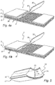
- the second layer 3b has, seen in cross-section transversely to the longitudinal direction of the adhesive tape 1, the form of a flap 30 which at one end is connected to the first layer 3a of hygroscopic material 3.
- the flap 30 may extend out to one longitudinal edge of the adhesive tape, as illustrated in Fig. 4a , or, as illustrated in Fig. 4b , merely have a narrow fastening surface 31 in connection with one connecting portion 4.
- the flap 30 is in direct contact with the vapour barrier 2.
- the opposite end of the flap 30 is free.
- Two adhesive connecting portions 4 are arranged in the longitudinal direction of the adhesive tape along two long sides of the adhesive tape so that they expose between them the free end 32 of the flap 30 of the hygroscopic material 3.
- the vapour barrier 2, the binder 6, the connecting portions 4 and the hygroscopic material 3 have been described above with reference to Fig. 1 and will therefore not be described once more in detail.
- the flap 30 of the hygroscopic material 3 has, seen in the cross-section of the adhesive tape 1, such a width that, when mounting the adhesive tape, it can be inserted into the joint/slot 11 which the adhesive tape 1 is adapted to seal.
- Fig. 5 shows the adhesive tape applied to a pipe shell 12 which in turn surrounds a pipe 13.
- the flap 30 may be resembled to a wick which obtains a large contact surface against the thermally insulating material 14 inside the pipe shell 12.
- the flap 30 has such a width that it is also arranged to be in contact with the pipe 13 surrounded by the pipe shell 12.
- the hygroscopic material 3 can absorb the condensate at the source thereof and divert and evaporate it to the ambient air through the vapour barrier 2 of the adhesive tape.
- Such an adhesive tape is particularly suited for pipe shells and can advantageously be delivered in a premounted on a pipe shell, that is so that the adhesive tape, by and along one of its connecting portions, is mounted on one side of the slot of the pipe shell.
- the flap When, in mounting, the pipe shell is forced in place over a pipe, the flap will simultaneously be pressed into the slot and put in contact with the pipe. Subsequently the protective strip is removed from the opposite connecting portion, after which the adhesive tape is made to adhere over the slot for sealing the same.
- FIG. 6a and Fig. 6b another embodiment of the adhesive tape 1 is shown.
- the embodiment corresponds to the embodiment that has been described above with reference to Figs 4a, 4b and 5 , except that the hygroscopic material 3 in the portion between the connecting portions 4 forms a loop 40 instead of a flap.
- the loop 40 is formed by the hygroscopic material 3 in this portion having a width that exceeds the distance between the opposite edges of the two connecting portions 4.
- the loop shape has the advantage that the hygroscopic material 3 in the loop 40 can spring outward and fill the space in a joint/slot so as to increase the contact surface between the hygroscopic material and the thermally insulating material and the element, respectively.
- the loop 40 of hygroscopic material 3 can extend out to the longitudinal edges of the adhesive tape 1 as shown in Fig. 6a or, as shown in Fig. 6b , have merely narrow fastening surfaces 41 adjacent to the connecting portions 4.
- the vapour barrier 2 is provided with a hole pattern 50 which puts the hygroscopic material 3 in direct contact with the ambient air and, thus, increases the evaporation surface.
- the hole pattern 50 is suitably arranged by the vapour barrier 2 being provided with a number of holes which is suitable for the application.
- the embodiment according to Fig. 7b differs from the one in Fig. 7a by the latter comprising a flap 30 of hygroscopic material 3. Seen in the cross-section of the adhesive tape, the flap 30 has such a width that, in mounting of the adhesive tape, it can be inserted into the joint which is adapted to be sealed by the adhesive tape.
- inventive adhesive tape can be used in combination with loose components of hygroscopic material.
Landscapes
- Engineering & Computer Science (AREA)
- General Engineering & Computer Science (AREA)
- Mechanical Engineering (AREA)
- Building Environments (AREA)
- Thermal Insulation (AREA)
- Insulating Bodies (AREA)
Claims (14)
- Klebeband zum Abdichten einer Verbindung in einem Isolationssystem, umfassend
eine erste Schicht, die eine Dampfsperre (2) bildet und die angepasst ist, eine Außenseite des Klebebandes (1) zu bilden,
ein hygroskopisches Material (3), das von der ersten Schicht getragen wird und, wenn das Klebeband zum Abdichten einer Verbindung in einem Isolationssystem aufgebracht wird, angepasst ist, in Kontakt mit der Verbindung zu stehen, und
mindestens einen klebenden Verbindungsabschnitt (4), der auf einer Innenseite des Klebebandes angeordnet ist und der beim Aufbringen des Klebebandes so ausgebildet ist, dass er auf mindestens einer Seite der Verbindung an dem Isolationssystem anhaftet. - Klebeband nach Anspruch 1, wobei die klebenden Verbindungsabschnitte (4) so angepasst sind, dass sie auf beiden Seiten der Verbindung an dem Isolationssystem anhaften.
- Klebeband nach Anspruch 1, wobei das hygroskopische Material (3) eine zweite Schicht bildet, wobei die zweite Schicht durch die erste Schicht getragen wird.
- Klebeband nach Anspruch 1, wobei das hygroskopische Material (3) in die erste Schicht integriert ist.
- Klebeband nach Anspruch 1, wobei das hygroskopische Material (3) einerseits in die erste Schicht integriert ist und andererseits eine zweite, von der Dampfsperre (4) getragene Schicht bildet, wobei die zweite Schicht mit dem hygroskopischen Material in der ersten Schicht in Kontakt steht.
- Klebeband nach einem der vorhergehenden Ansprüche, wobei das hygroskopische Material (3) mindestens teilweise eine nichtkontinuierliche Struktur aufweist.
- Klebeband nach einem der vorhergehenden Ansprüche, wobei sich das hygroskopische Material (3) über eine gesamte Oberfläche erstreckt, die von der Außenseite der ersten Schicht abgewandt ist.
- Klebeband nach einem der vorhergehenden Ansprüche, wobei das hygroskopische Material (3), wenn das Klebeband aufgebracht wird, in die Verbindung in dem Isolationssystem einsetzbar ist.
- Klebeband nach einem der vorhergehenden Ansprüche, wobei das hygroskopische Material (3) ein freies Ende aufweist, das aus der ersten Schicht herausragt und das, wenn das Klebeband aufgebracht wird, in die Verbindung in dem Isolationssystem einsetzbar ist.
- Klebeband nach einem der Ansprüche 1 bis 7, wobei das hygroskopische Material (3) zwischen den Verbindungsabschnitten (4) eine Schlaufe (40) ausbildet, wobei die Schlaufe, wenn das Klebeband aufgebracht wird, in die Verbindung in dem Isolationssystem einsetzbar ist.
- Klebeband nach einem der vorhergehenden Ansprüche, wobei die erste Schicht Perforationen (7) aufweist, über die das hygroskopische Material (3) mit der Umgebungsluft in Kontakt steht.
- Klebeband nach einem der vorhergehenden Ansprüche, wobei das hygroskopische Material (3) Verdampfungsflächen aufweist, die in der Dickenrichtung des Klebebandes angeordnet sind, wobei über die Verdampfungsflächen das hygroskopische Material mit der Umgebungsluft in Kontakt steht.
- Verfahren zum Abdichten einer Verbindung in einem Isolationssystem, umfassend das Aufbringen eines Klebebandes (1), das eine Dampfsperre (2), die eine Außenseite bildet, und ein hygroskopisches Material (3) aufweist, das von der Dampfsperre getragen wird, auf die Verbindung in einer derartigen Weise, dass das hygroskopische Material mit der Verbindung in Kontakt gebracht wird und so, dass das Klebeband (1) auf mindestens einer Seite der Verbindung an dem Isolationssystem anhaftet.
- Verfahren nach Anspruch 13, umfassend den Schritt des Einsetzens von mindestens Abschnitten des hygroskopischen Materials (3), das von der Dampfsperre (2) getragen wird, in die Verbindung.
Priority Applications (2)
| Application Number | Priority Date | Filing Date | Title |
|---|---|---|---|
| SI200732129T SI2069679T1 (sl) | 2006-09-22 | 2007-09-21 | Lepilni trak za tesnjenje spoja v izolacijskem sistemu in postopek za tesnjenje takšnega spoja |
| PL07835049T PL2069679T3 (pl) | 2006-09-22 | 2007-09-21 | Taśma adhezyjna do uszczelniania złącza w systemie izolacyjnym i sposób uszczelnienia takiego złącza |
Applications Claiming Priority (2)
| Application Number | Priority Date | Filing Date | Title |
|---|---|---|---|
| SE0601967A SE530313C2 (sv) | 2006-09-22 | 2006-09-22 | Tejp för förslutning av en skarv i ett isoleringssystem, samt metod för förslutning av en dylik skarv |
| PCT/SE2007/000827 WO2008036025A1 (en) | 2006-09-22 | 2007-09-21 | Adhesive tape for sealing a joint in an insulation system, and method for sealing such a joint |
Publications (3)
| Publication Number | Publication Date |
|---|---|
| EP2069679A1 EP2069679A1 (de) | 2009-06-17 |
| EP2069679A4 EP2069679A4 (de) | 2016-09-28 |
| EP2069679B1 true EP2069679B1 (de) | 2019-07-03 |
Family
ID=39200765
Family Applications (1)
| Application Number | Title | Priority Date | Filing Date |
|---|---|---|---|
| EP07835049.3A Active EP2069679B1 (de) | 2006-09-22 | 2007-09-21 | Klebeband zur abdichtung einer verbindung in einem isolationssystem und verfahren zur abdichtung einer solchen verbindung |
Country Status (7)
| Country | Link |
|---|---|
| EP (1) | EP2069679B1 (de) |
| DK (1) | DK2069679T3 (de) |
| ES (1) | ES2738509T3 (de) |
| PL (1) | PL2069679T3 (de) |
| SE (1) | SE530313C2 (de) |
| SI (1) | SI2069679T1 (de) |
| WO (1) | WO2008036025A1 (de) |
Families Citing this family (1)
| Publication number | Priority date | Publication date | Assignee | Title |
|---|---|---|---|---|
| CN103492780B (zh) * | 2011-01-25 | 2016-10-26 | Rns技术有限公司 | 隔绝组合物以及检测隔绝组合物中的水的方法 |
Family Cites Families (7)
| Publication number | Priority date | Publication date | Assignee | Title |
|---|---|---|---|---|
| US4595615A (en) * | 1984-10-05 | 1986-06-17 | Venture Tape Corp. | Pipe insulation for cold weather applications |
| DK164303C (da) * | 1990-05-14 | 1992-10-19 | Vik Consult | Isolering til et roer eller en kanal med en relativ lav overfladetemperatur og fremgangsmaade til fremstilling af isoleringen |
| US5520009A (en) * | 1992-08-31 | 1996-05-28 | Rockwool International A/S | Method and apparatus for insulating |
| US5417901A (en) * | 1992-12-24 | 1995-05-23 | Industrial Thermo Polymers Limited | Method of forming pipe insulation with prestressed tape closure |
| DK0739470T3 (da) * | 1994-01-14 | 1998-11-23 | Rockwool Int | Fremgangsmåde og apparat til isolering |
| US20010031329A1 (en) * | 2000-01-21 | 2001-10-18 | Shaffer Roy E. | Unitary vapor retarder for chilled pipe insulation |
| SE525985C2 (sv) * | 2003-10-17 | 2005-06-07 | Saint Gobain Isover Ab | Isoleringssystem till tekniska installationer |
-
2006
- 2006-09-22 SE SE0601967A patent/SE530313C2/sv not_active IP Right Cessation
-
2007
- 2007-09-21 PL PL07835049T patent/PL2069679T3/pl unknown
- 2007-09-21 ES ES07835049T patent/ES2738509T3/es active Active
- 2007-09-21 WO PCT/SE2007/000827 patent/WO2008036025A1/en active Application Filing
- 2007-09-21 SI SI200732129T patent/SI2069679T1/sl unknown
- 2007-09-21 DK DK07835049.3T patent/DK2069679T3/da active
- 2007-09-21 EP EP07835049.3A patent/EP2069679B1/de active Active
Non-Patent Citations (1)
| Title |
|---|
| None * |
Also Published As
| Publication number | Publication date |
|---|---|
| EP2069679A4 (de) | 2016-09-28 |
| SI2069679T1 (sl) | 2019-11-29 |
| EP2069679A1 (de) | 2009-06-17 |
| DK2069679T3 (da) | 2019-08-26 |
| WO2008036025A1 (en) | 2008-03-27 |
| SE530313C2 (sv) | 2008-04-29 |
| ES2738509T3 (es) | 2020-01-23 |
| PL2069679T3 (pl) | 2019-10-31 |
| SE0601967L (sv) | 2008-03-23 |
Similar Documents
| Publication | Publication Date | Title |
|---|---|---|
| EP1687561B1 (de) | Isolationssystem für technische anlagen | |
| RU2441119C2 (ru) | Композиционный теплоизоляционный материал | |
| US5690147A (en) | Method and apparatus for insulating | |
| US20060123723A1 (en) | Wall finishing panel system | |
| DK164303B (da) | Isolering til et roer eller en kanal med en relativ lav overfladetemperatur og fremgangsmaade til fremstilling af isoleringen | |
| HU227328B1 (en) | Use of ionomers for sealing insulating materials | |
| HU219093B (hu) | Szigetelőlemez, valamint eljárás ennek előállítására | |
| CA2398079C (en) | Unitary vapor retarder for chilled pipe insulation | |
| KR20090066087A (ko) | 건축용 복합기능의 진공 방화심재 | |
| GB2449985A (en) | Thermal insulation having securing flaps compensating for variation in coverage | |
| CA2236271A1 (en) | An insulation system and a method of providing an insulation system on a pipe or a container ("insulation system") | |
| EP2069679B1 (de) | Klebeband zur abdichtung einer verbindung in einem isolationssystem und verfahren zur abdichtung einer solchen verbindung | |
| SE527024E (sv) | Ytbeklädnadsmaterial i laminatform samt isoleringssystem innefattande ett dylikt ytbeklädnadsmaterial | |
| JP5514015B2 (ja) | 断熱材付き内装建材 | |
| GB2427011A (en) | Insulation for ducting having channels | |
| KR200409425Y1 (ko) | 단열성 및 불연성이 개선된 통기성 열반사 단열재(2) | |
| JPS647175B2 (de) | ||
| JPH10252171A (ja) | 無機質繊維天井板 | |
| JPS61225445A (ja) | 断熱防露屋根 | |
| JPH0453987B2 (de) |
Legal Events
| Date | Code | Title | Description |
|---|---|---|---|
| PUAI | Public reference made under article 153(3) epc to a published international application that has entered the european phase |
Free format text: ORIGINAL CODE: 0009012 |
|
| 17P | Request for examination filed |
Effective date: 20090416 |
|
| AK | Designated contracting states |
Kind code of ref document: A1 Designated state(s): AT BE BG CH CY CZ DE DK EE ES FI FR GB GR HU IE IS IT LI LT LU LV MC MT NL PL PT RO SE SI SK TR |
|
| DAX | Request for extension of the european patent (deleted) | ||
| RA4 | Supplementary search report drawn up and despatched (corrected) |
Effective date: 20160830 |
|
| RIC1 | Information provided on ipc code assigned before grant |
Ipc: F16L 59/02 20060101ALI20160824BHEP Ipc: B32B 1/08 20060101ALI20160824BHEP Ipc: F16L 59/10 20060101AFI20160824BHEP |
|
| RIC1 | Information provided on ipc code assigned before grant |
Ipc: B32B 1/08 20060101ALI20181127BHEP Ipc: F16L 59/10 20060101AFI20181127BHEP Ipc: F16L 59/02 20060101ALI20181127BHEP |
|
| GRAP | Despatch of communication of intention to grant a patent |
Free format text: ORIGINAL CODE: EPIDOSNIGR1 |
|
| STAA | Information on the status of an ep patent application or granted ep patent |
Free format text: STATUS: GRANT OF PATENT IS INTENDED |
|
| INTG | Intention to grant announced |
Effective date: 20190107 |
|
| GRAS | Grant fee paid |
Free format text: ORIGINAL CODE: EPIDOSNIGR3 |
|
| GRAA | (expected) grant |
Free format text: ORIGINAL CODE: 0009210 |
|
| STAA | Information on the status of an ep patent application or granted ep patent |
Free format text: STATUS: THE PATENT HAS BEEN GRANTED |
|
| AK | Designated contracting states |
Kind code of ref document: B1 Designated state(s): AT BE BG CH CY CZ DE DK EE ES FI FR GB GR HU IE IS IT LI LT LU LV MC MT NL PL PT RO SE SI SK TR |
|
| REG | Reference to a national code |
Ref country code: GB Ref legal event code: FG4D |
|
| REG | Reference to a national code |
Ref country code: CH Ref legal event code: EP Ref country code: AT Ref legal event code: REF Ref document number: 1151437 Country of ref document: AT Kind code of ref document: T Effective date: 20190715 |
|
| REG | Reference to a national code |
Ref country code: DE Ref legal event code: R096 Ref document number: 602007058753 Country of ref document: DE |
|
| REG | Reference to a national code |
Ref country code: IE Ref legal event code: FG4D |
|
| REG | Reference to a national code |
Ref country code: CH Ref legal event code: NV Representative=s name: DENNEMEYER AG, CH |
|
| REG | Reference to a national code |
Ref country code: DK Ref legal event code: T3 Effective date: 20190822 |
|
| REG | Reference to a national code |
Ref country code: NL Ref legal event code: FP |
|
| REG | Reference to a national code |
Ref country code: SE Ref legal event code: TRGR |
|
| REG | Reference to a national code |
Ref country code: SK Ref legal event code: T3 Ref document number: E 31767 Country of ref document: SK |
|
| REG | Reference to a national code |
Ref country code: LT Ref legal event code: MG4D |
|
| REG | Reference to a national code |
Ref country code: AT Ref legal event code: MK05 Ref document number: 1151437 Country of ref document: AT Kind code of ref document: T Effective date: 20190703 |
|
| REG | Reference to a national code |
Ref country code: ES Ref legal event code: FG2A Ref document number: 2738509 Country of ref document: ES Kind code of ref document: T3 Effective date: 20200123 |
|
| PG25 | Lapsed in a contracting state [announced via postgrant information from national office to epo] |
Ref country code: BG Free format text: LAPSE BECAUSE OF FAILURE TO SUBMIT A TRANSLATION OF THE DESCRIPTION OR TO PAY THE FEE WITHIN THE PRESCRIBED TIME-LIMIT Effective date: 20191003 Ref country code: AT Free format text: LAPSE BECAUSE OF FAILURE TO SUBMIT A TRANSLATION OF THE DESCRIPTION OR TO PAY THE FEE WITHIN THE PRESCRIBED TIME-LIMIT Effective date: 20190703 Ref country code: LT Free format text: LAPSE BECAUSE OF FAILURE TO SUBMIT A TRANSLATION OF THE DESCRIPTION OR TO PAY THE FEE WITHIN THE PRESCRIBED TIME-LIMIT Effective date: 20190703 Ref country code: PT Free format text: LAPSE BECAUSE OF FAILURE TO SUBMIT A TRANSLATION OF THE DESCRIPTION OR TO PAY THE FEE WITHIN THE PRESCRIBED TIME-LIMIT Effective date: 20191104 |
|
| PG25 | Lapsed in a contracting state [announced via postgrant information from national office to epo] |
Ref country code: LV Free format text: LAPSE BECAUSE OF FAILURE TO SUBMIT A TRANSLATION OF THE DESCRIPTION OR TO PAY THE FEE WITHIN THE PRESCRIBED TIME-LIMIT Effective date: 20190703 Ref country code: GR Free format text: LAPSE BECAUSE OF FAILURE TO SUBMIT A TRANSLATION OF THE DESCRIPTION OR TO PAY THE FEE WITHIN THE PRESCRIBED TIME-LIMIT Effective date: 20191004 Ref country code: IS Free format text: LAPSE BECAUSE OF FAILURE TO SUBMIT A TRANSLATION OF THE DESCRIPTION OR TO PAY THE FEE WITHIN THE PRESCRIBED TIME-LIMIT Effective date: 20191103 |
|
| PG25 | Lapsed in a contracting state [announced via postgrant information from national office to epo] |
Ref country code: RO Free format text: LAPSE BECAUSE OF FAILURE TO SUBMIT A TRANSLATION OF THE DESCRIPTION OR TO PAY THE FEE WITHIN THE PRESCRIBED TIME-LIMIT Effective date: 20190703 Ref country code: EE Free format text: LAPSE BECAUSE OF FAILURE TO SUBMIT A TRANSLATION OF THE DESCRIPTION OR TO PAY THE FEE WITHIN THE PRESCRIBED TIME-LIMIT Effective date: 20190703 |
|
| PG25 | Lapsed in a contracting state [announced via postgrant information from national office to epo] |
Ref country code: MC Free format text: LAPSE BECAUSE OF FAILURE TO SUBMIT A TRANSLATION OF THE DESCRIPTION OR TO PAY THE FEE WITHIN THE PRESCRIBED TIME-LIMIT Effective date: 20190703 Ref country code: IS Free format text: LAPSE BECAUSE OF FAILURE TO SUBMIT A TRANSLATION OF THE DESCRIPTION OR TO PAY THE FEE WITHIN THE PRESCRIBED TIME-LIMIT Effective date: 20200224 |
|
| REG | Reference to a national code |
Ref country code: DE Ref legal event code: R097 Ref document number: 602007058753 Country of ref document: DE |
|
| RAP2 | Party data changed (patent owner data changed or rights of a patent transferred) |
Owner name: SAINT-GOBAIN ISOVER |
|
| PLBE | No opposition filed within time limit |
Free format text: ORIGINAL CODE: 0009261 |
|
| STAA | Information on the status of an ep patent application or granted ep patent |
Free format text: STATUS: NO OPPOSITION FILED WITHIN TIME LIMIT |
|
| PG2D | Information on lapse in contracting state deleted |
Ref country code: IS |
|
| PG25 | Lapsed in a contracting state [announced via postgrant information from national office to epo] |
Ref country code: IE Free format text: LAPSE BECAUSE OF NON-PAYMENT OF DUE FEES Effective date: 20190921 Ref country code: LU Free format text: LAPSE BECAUSE OF NON-PAYMENT OF DUE FEES Effective date: 20190921 |
|
| REG | Reference to a national code |
Ref country code: BE Ref legal event code: MM Effective date: 20190930 |
|
| 26N | No opposition filed |
Effective date: 20200603 |
|
| PG25 | Lapsed in a contracting state [announced via postgrant information from national office to epo] |
Ref country code: BE Free format text: LAPSE BECAUSE OF NON-PAYMENT OF DUE FEES Effective date: 20190930 |
|
| PG25 | Lapsed in a contracting state [announced via postgrant information from national office to epo] |
Ref country code: CY Free format text: LAPSE BECAUSE OF FAILURE TO SUBMIT A TRANSLATION OF THE DESCRIPTION OR TO PAY THE FEE WITHIN THE PRESCRIBED TIME-LIMIT Effective date: 20190703 |
|
| PG25 | Lapsed in a contracting state [announced via postgrant information from national office to epo] |
Ref country code: HU Free format text: LAPSE BECAUSE OF FAILURE TO SUBMIT A TRANSLATION OF THE DESCRIPTION OR TO PAY THE FEE WITHIN THE PRESCRIBED TIME-LIMIT; INVALID AB INITIO Effective date: 20070921 Ref country code: MT Free format text: LAPSE BECAUSE OF FAILURE TO SUBMIT A TRANSLATION OF THE DESCRIPTION OR TO PAY THE FEE WITHIN THE PRESCRIBED TIME-LIMIT Effective date: 20190703 |
|
| PGFP | Annual fee paid to national office [announced via postgrant information from national office to epo] |
Ref country code: NL Payment date: 20220819 Year of fee payment: 16 |
|
| PGFP | Annual fee paid to national office [announced via postgrant information from national office to epo] |
Ref country code: TR Payment date: 20220921 Year of fee payment: 16 Ref country code: SK Payment date: 20220815 Year of fee payment: 16 Ref country code: IT Payment date: 20220811 Year of fee payment: 16 Ref country code: GB Payment date: 20220804 Year of fee payment: 16 Ref country code: FI Payment date: 20220909 Year of fee payment: 16 Ref country code: DE Payment date: 20220803 Year of fee payment: 16 |
|
| PGFP | Annual fee paid to national office [announced via postgrant information from national office to epo] |
Ref country code: SI Payment date: 20220818 Year of fee payment: 16 Ref country code: PL Payment date: 20220812 Year of fee payment: 16 Ref country code: FR Payment date: 20220930 Year of fee payment: 16 |
|
| PGFP | Annual fee paid to national office [announced via postgrant information from national office to epo] |
Ref country code: ES Payment date: 20221004 Year of fee payment: 16 |
|
| PGFP | Annual fee paid to national office [announced via postgrant information from national office to epo] |
Ref country code: CH Payment date: 20221001 Year of fee payment: 16 |
|
| PGFP | Annual fee paid to national office [announced via postgrant information from national office to epo] |
Ref country code: CZ Payment date: 20230831 Year of fee payment: 17 |
|
| PGFP | Annual fee paid to national office [announced via postgrant information from national office to epo] |
Ref country code: SE Payment date: 20230810 Year of fee payment: 17 Ref country code: DK Payment date: 20230914 Year of fee payment: 17 |
|
| REG | Reference to a national code |
Ref country code: DE Ref legal event code: R119 Ref document number: 602007058753 Country of ref document: DE |
|
| PG25 | Lapsed in a contracting state [announced via postgrant information from national office to epo] |
Ref country code: FI Free format text: LAPSE BECAUSE OF NON-PAYMENT OF DUE FEES Effective date: 20230921 |
|
| REG | Reference to a national code |
Ref country code: CH Ref legal event code: PL |
|
| REG | Reference to a national code |
Ref country code: NL Ref legal event code: MM Effective date: 20231001 |
|
| REG | Reference to a national code |
Ref country code: SK Ref legal event code: MM4A Ref document number: E 31767 Country of ref document: SK Effective date: 20230921 |