EP2068732B1 - Trocart de visualisation - Google Patents
Trocart de visualisation Download PDFInfo
- Publication number
- EP2068732B1 EP2068732B1 EP07839288.3A EP07839288A EP2068732B1 EP 2068732 B1 EP2068732 B1 EP 2068732B1 EP 07839288 A EP07839288 A EP 07839288A EP 2068732 B1 EP2068732 B1 EP 2068732B1
- Authority
- EP
- European Patent Office
- Prior art keywords
- tip
- penetrating
- facets
- penetrating tip
- edge
- Prior art date
- Legal status (The legal status is an assumption and is not a legal conclusion. Google has not performed a legal analysis and makes no representation as to the accuracy of the status listed.)
- Active
Links
- 238000012800 visualization Methods 0.000 title description 5
- 230000000149 penetrating effect Effects 0.000 claims description 89
- 230000003287 optical effect Effects 0.000 claims description 16
- 239000000463 material Substances 0.000 claims description 11
- 238000005520 cutting process Methods 0.000 claims description 7
- 239000004033 plastic Substances 0.000 claims description 5
- 229920003023 plastic Polymers 0.000 claims description 5
- 239000004417 polycarbonate Substances 0.000 claims description 3
- 229920000515 polycarbonate Polymers 0.000 claims description 3
- 238000003780 insertion Methods 0.000 description 16
- 230000037431 insertion Effects 0.000 description 16
- 210000003815 abdominal wall Anatomy 0.000 description 14
- 210000001519 tissue Anatomy 0.000 description 11
- 238000000034 method Methods 0.000 description 6
- 238000001356 surgical procedure Methods 0.000 description 5
- 241001631457 Cannula Species 0.000 description 4
- 210000003484 anatomy Anatomy 0.000 description 4
- 230000004313 glare Effects 0.000 description 4
- 238000000465 moulding Methods 0.000 description 4
- 230000005540 biological transmission Effects 0.000 description 3
- 230000008859 change Effects 0.000 description 3
- 238000004519 manufacturing process Methods 0.000 description 3
- 230000003187 abdominal effect Effects 0.000 description 2
- 239000011248 coating agent Substances 0.000 description 2
- 238000000576 coating method Methods 0.000 description 2
- 238000003384 imaging method Methods 0.000 description 2
- 210000003200 peritoneal cavity Anatomy 0.000 description 2
- 229920003229 poly(methyl methacrylate) Polymers 0.000 description 2
- 239000004926 polymethyl methacrylate Substances 0.000 description 2
- 239000007787 solid Substances 0.000 description 2
- 208000012260 Accidental injury Diseases 0.000 description 1
- 210000001015 abdomen Anatomy 0.000 description 1
- NIXOWILDQLNWCW-UHFFFAOYSA-N acrylic acid group Chemical group C(C=C)(=O)O NIXOWILDQLNWCW-UHFFFAOYSA-N 0.000 description 1
- 230000004075 alteration Effects 0.000 description 1
- 230000015572 biosynthetic process Effects 0.000 description 1
- 239000013078 crystal Substances 0.000 description 1
- 238000000151 deposition Methods 0.000 description 1
- 230000000694 effects Effects 0.000 description 1
- 238000005755 formation reaction Methods 0.000 description 1
- 230000006870 function Effects 0.000 description 1
- 239000011521 glass Substances 0.000 description 1
- 238000005286 illumination Methods 0.000 description 1
- 238000001746 injection moulding Methods 0.000 description 1
- 208000014674 injury Diseases 0.000 description 1
- 210000000936 intestine Anatomy 0.000 description 1
- 230000013011 mating Effects 0.000 description 1
- 238000012978 minimally invasive surgical procedure Methods 0.000 description 1
- 239000013307 optical fiber Substances 0.000 description 1
- 210000000056 organ Anatomy 0.000 description 1
- 238000010422 painting Methods 0.000 description 1
- 230000035515 penetration Effects 0.000 description 1
- 230000008447 perception Effects 0.000 description 1
- 210000004303 peritoneum Anatomy 0.000 description 1
- 238000002360 preparation method Methods 0.000 description 1
- 238000007788 roughening Methods 0.000 description 1
- 238000007650 screen-printing Methods 0.000 description 1
- 238000007789 sealing Methods 0.000 description 1
- 239000000243 solution Substances 0.000 description 1
- 239000002904 solvent Substances 0.000 description 1
- 230000007704 transition Effects 0.000 description 1
- 238000003466 welding Methods 0.000 description 1
Images


Classifications
-
- A—HUMAN NECESSITIES
- A61—MEDICAL OR VETERINARY SCIENCE; HYGIENE
- A61B—DIAGNOSIS; SURGERY; IDENTIFICATION
- A61B17/00—Surgical instruments, devices or methods, e.g. tourniquets
- A61B17/34—Trocars; Puncturing needles
- A61B17/3417—Details of tips or shafts, e.g. grooves, expandable, bendable; Multiple coaxial sliding cannulas, e.g. for dilating
- A61B17/3421—Cannulas
- A61B17/3423—Access ports, e.g. toroid shape introducers for instruments or hands
-
- A—HUMAN NECESSITIES
- A61—MEDICAL OR VETERINARY SCIENCE; HYGIENE
- A61B—DIAGNOSIS; SURGERY; IDENTIFICATION
- A61B17/00—Surgical instruments, devices or methods, e.g. tourniquets
- A61B17/34—Trocars; Puncturing needles
- A61B17/3498—Valves therefor, e.g. flapper valves, slide valves
-
- A—HUMAN NECESSITIES
- A61—MEDICAL OR VETERINARY SCIENCE; HYGIENE
- A61B—DIAGNOSIS; SURGERY; IDENTIFICATION
- A61B17/00—Surgical instruments, devices or methods, e.g. tourniquets
- A61B2017/0046—Surgical instruments, devices or methods, e.g. tourniquets with a releasable handle; with handle and operating part separable
- A61B2017/00473—Distal part, e.g. tip or head
-
- A—HUMAN NECESSITIES
- A61—MEDICAL OR VETERINARY SCIENCE; HYGIENE
- A61B—DIAGNOSIS; SURGERY; IDENTIFICATION
- A61B17/00—Surgical instruments, devices or methods, e.g. tourniquets
- A61B2017/00831—Material properties
- A61B2017/00902—Material properties transparent or translucent
- A61B2017/00907—Material properties transparent or translucent for light
-
- A—HUMAN NECESSITIES
- A61—MEDICAL OR VETERINARY SCIENCE; HYGIENE
- A61B—DIAGNOSIS; SURGERY; IDENTIFICATION
- A61B17/00—Surgical instruments, devices or methods, e.g. tourniquets
- A61B17/34—Trocars; Puncturing needles
- A61B17/3417—Details of tips or shafts, e.g. grooves, expandable, bendable; Multiple coaxial sliding cannulas, e.g. for dilating
- A61B2017/3454—Details of tips
- A61B2017/3456—Details of tips blunt
-
- A—HUMAN NECESSITIES
- A61—MEDICAL OR VETERINARY SCIENCE; HYGIENE
- A61B—DIAGNOSIS; SURGERY; IDENTIFICATION
- A61B17/00—Surgical instruments, devices or methods, e.g. tourniquets
- A61B17/34—Trocars; Puncturing needles
- A61B2017/347—Locking means, e.g. for locking instrument in cannula
-
- A—HUMAN NECESSITIES
- A61—MEDICAL OR VETERINARY SCIENCE; HYGIENE
- A61B—DIAGNOSIS; SURGERY; IDENTIFICATION
- A61B90/00—Instruments, implements or accessories specially adapted for surgery or diagnosis and not covered by any of the groups A61B1/00 - A61B50/00, e.g. for luxation treatment or for protecting wound edges
- A61B90/06—Measuring instruments not otherwise provided for
- A61B2090/064—Measuring instruments not otherwise provided for for measuring force, pressure or mechanical tension
-
- A—HUMAN NECESSITIES
- A61—MEDICAL OR VETERINARY SCIENCE; HYGIENE
- A61B—DIAGNOSIS; SURGERY; IDENTIFICATION
- A61B90/00—Instruments, implements or accessories specially adapted for surgery or diagnosis and not covered by any of the groups A61B1/00 - A61B50/00, e.g. for luxation treatment or for protecting wound edges
- A61B90/36—Image-producing devices or illumination devices not otherwise provided for
- A61B90/361—Image-producing devices, e.g. surgical cameras
- A61B2090/3614—Image-producing devices, e.g. surgical cameras using optical fibre
-
- A—HUMAN NECESSITIES
- A61—MEDICAL OR VETERINARY SCIENCE; HYGIENE
- A61B—DIAGNOSIS; SURGERY; IDENTIFICATION
- A61B90/00—Instruments, implements or accessories specially adapted for surgery or diagnosis and not covered by any of the groups A61B1/00 - A61B50/00, e.g. for luxation treatment or for protecting wound edges
- A61B90/36—Image-producing devices or illumination devices not otherwise provided for
- A61B90/37—Surgical systems with images on a monitor during operation
- A61B2090/373—Surgical systems with images on a monitor during operation using light, e.g. by using optical scanners
-
- A—HUMAN NECESSITIES
- A61—MEDICAL OR VETERINARY SCIENCE; HYGIENE
- A61B—DIAGNOSIS; SURGERY; IDENTIFICATION
- A61B34/00—Computer-aided surgery; Manipulators or robots specially adapted for use in surgery
- A61B34/10—Computer-aided planning, simulation or modelling of surgical operations
-
- A—HUMAN NECESSITIES
- A61—MEDICAL OR VETERINARY SCIENCE; HYGIENE
- A61B—DIAGNOSIS; SURGERY; IDENTIFICATION
- A61B50/00—Containers, covers, furniture or holders specially adapted for surgical or diagnostic appliances or instruments, e.g. sterile covers
- A61B50/30—Containers specially adapted for packaging, protecting, dispensing, collecting or disposing of surgical or diagnostic appliances or instruments
-
- A—HUMAN NECESSITIES
- A61—MEDICAL OR VETERINARY SCIENCE; HYGIENE
- A61B—DIAGNOSIS; SURGERY; IDENTIFICATION
- A61B90/00—Instruments, implements or accessories specially adapted for surgery or diagnosis and not covered by any of the groups A61B1/00 - A61B50/00, e.g. for luxation treatment or for protecting wound edges
- A61B90/36—Image-producing devices or illumination devices not otherwise provided for
- A61B90/37—Surgical systems with images on a monitor during operation
Definitions
- the present invention relates to surgical instruments such as trocars for use in insertion of surgical access devices, such as access cannulas.
- surgical access devices such as access cannulas.
- the present invention is directed to such insertion devices having a transparent tip to allow visualization of tissue being penetrated.
- a variety of devices and methods are known in the art for insertion of surgical access devices, such as surgical cannulas in minimally-invasive surgical procedures. Of such devices, many are configured to puncture a patient's abdominal wall. Most of such insertion devices are fully solid and opaque, so a surgeon cannot easily visually differentiate between layers of the abdominal wall and internal abdominal organs.
- Some insertion devices have been developed that include a transparent tip or an integral endoscope While such devices can offer improved guidance to a surgeon over those with no means for visualization, such devices can be relatively complex, difficult to manufacture, and therefore can be expensive.
- EP 1 707 132 A2 discloses a tip according to the preamble of claim 1.
- EP 1 685 792 A1 discloses a penetrating tip for a surgical trocar having a generally transparent body having inwardly tapered opposed facets formed at a distal end of the body.
- the facets converge with one another at an integral edge which is inclined relatively to an axis of the body and ends in a pin tip at the circumference of the body.
- three inwardly tapered facets are formed in the body which converge with one another at a central pin tip at the distal end of the body.
- the invention is characterized by the features of claim 1.
- the penetrating tip includes a generally transparent body, having proximal and distal ends.
- the body has an opaque distal tip portion, which can be used as a guide or indicator, and/or to reduce glare, as described in more detail below.
- the body also has an integral penetrating edge arranged at a distal end of the body, and inwardly tapered opposed facets formed in the body, converging with one another at the integral penetrating edge, which can be a dissecting edge, a cutting edge or a blunt edge, for example.
- the penetrating edge is arranged on the tip in the distal end portion thereof, and not necessarily at the distal end thereof.
- the tip can further include an expanded-diameter region for engaging a surgical access device.
- the tip can be formed by molding, such as by injection molding.
- the tip's opposed facets are substantially planar.
- Opposed facets are provided on the tip at a predetermined angle with respect to one another, such as at 20 degrees or 30 degrees. In other embodiments in accordance with the invention, the facets are provided at an angle of about 40 degrees, with respect to one another. It is therefore to be understood that a relative angle of between about 5 and about 90 degrees, at any increment of one-degree therebetween may be used for tips in accordance with the invention.
- the penetrating edge of the tip can be substantially straight or convexly arcuate in configuration. If desired, a locking element can be provided on the body for engaging a trocar or other insertion device. Tips in accordance with the invention can further include an inner optical surface configured so as to minimize distortion of images taken through the penetrating tip.
- the tips can be formed of a plastic material, which can be, for example, polycarbonate plastic or polymethyl methacrylate.
- the present invention may be used for insertion of surgical access devices or other devices that require the puncture of biological tissue.
- the present invention is particularly suited for insertion of surgical access devices or cannulas (or "cannulae") through the abdominal wall of a patient, in order to provide a working channel through which a surgical procedure can be performed.
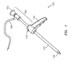
- a visualization trocar 100 which includes a handle 110, a shaft 120 extending from the handle 110, and a penetrating tip 130 arranged at the distal end of the shaft 120.
- the trocar 100 can be used with an endoscope 190 having an eyepiece 193 at a distal end thereof, which receives images through an optical path from a lens (not shown) situated on the endoscope 190 near the penetrating tip 130.
- images are typically transmitted by way of a transparent medium within the endoscope 190, such as an optical shaft or one or more optical fibers.
- an attachment having an image sensor can be secured to the endoscope 190 on or in place of the eyepiece 193.
- the endoscope 190 can further be provided with a secondary optical conduit 180, which can transmit light to the penetrating tip 130.
- the trocar 100 can be provided with an integral endoscope, including all of the features thereof contained in one integral device.
- an image sensor can be provided within the trocar 100 at the distal end thereof- in the shaft 120 or within the penetrating tip 130. Accordingly, electrical rather than optical connections then extend through the shaft 120 to a display device, such as a video monitor.
- a locking element 170 can be provided in the handle portion 110 of the trocar 100.
- the locking element 170 engages the endoscope 190 passing through the handle 110, to prevent at a minimum, relative axial movement between the trocar 100 and the endoscope 190. Additionally, relative rotational movement can be inhibited, if desired.
- trocar 100 itself can vary, and can include additional features, as needed or desired.
- cannulae utilized with the trocar 100 can include one or more demarcations thereon, which indicate the progress of insertion, and can therefore signal to the surgeon when the cannula has been inserted sufficiently.
- the geometry of the penetrating tip 130 can change as desired, as will become apparent through understanding of the various embodiments of penetrating tips, which are set forth hereinbelow.
- the term "trocar” is used herein to refer generally to an insertion device, which is capable of puncturing an anatomical structure, such as an abdominal wall, to insert a surgical access device or "port" to aid in performing a surgical procedure.
- FIG. 2 an isometric view of an exemplary embodiment of a penetrating tip is shown in Figure 2 and is designated generally by reference number 200.
- the penetrating tip 200 includes a body 210, at its proximal end having a reduced-diameter portion 219, and one or more rotation locking elements 217, each of which interfaces with the shaft of a trocar (e.g., shaft 120 of trocar 100).
- a trocar e.g., shaft 120 of trocar 100.
- the reduced-diameter portion 219 is inserted into the shaft of a trocar, thereby enabling secure mutual engagement therebetween, while the rotation locking element(s) 217 engage a mating element, such as a groove, notch or recess in the shaft of the trocar, preventing relative rotation between the penetrating tip 200 and the trocar shaft. If, however, the tip 200 is manufactured integrally with a trocar, relative positioning can be achieved and maintained in another manner, such as integrally molding, insert molding, adhering, bonding or welding the components by heat, solvent or friction, or by another suitable manufacturing technique.
- the distal end of the penetrating tip 200 includes a distal taper 215 of the body 210, and two opposed angled facets 220, which are angled inwardly, approaching the penetrating edge 240 at the distal end of the tip 200.
- the facets 220 are substantially planar in this embodiment, and are delimited partially by a change in contour indicated by arcuate contour interface 230 with the body 210, and partially by the distal penetrating edge 240.
- the facets 220 are angled, with respect to one another at an angle ⁇ (alpha).
- the angle ⁇ can be anywhere from about 5 degrees to about 90 degrees, inclusive, at any one-degree increment therebetween. In one embodiment, the angle ⁇ is about 30 degrees, and in another embodiment the angle ⁇ is about 40 degrees, for example.
- the tip 200 is inserted into a trocar, such as trocar 100 of Figure 1 , or alternatively is manufactured integrally therewith.
- the tip 200 can be manufactured from any suitable material, but is preferably transparent, to allow a surgeon to view the layers of tissue through which the surgeon is penetrating.
- Such materials can include, for example, polycarbonate plastic, polymethyl methacrylate ("acrylic"), a vitreous material such as glass, or an optical crystal material. Accordingly, the surgeon is able to view the tissue through which the trocar and tip 200 are passing. The surgeon is able, therefore, to determine by the general appearance of the tissue, the point at which the tip 200 has penetrated to a sufficient depth. During an abdominal procedure, the depth will typically be a point at which the tip 200 has just entered the peritoneal cavity.
- the tip 200 can be provided with any desired degree of sharpness. That is, the penetrating tip 240 can be formed to have a sharp point, a dissecting edge or can be rounded to any desired degree in order to provide a relatively blunt leading edge. When provided with a relatively blunt tip 240, accidental injury to internal anatomical structures, such as intestines, can be reduced.
- FIG 3 is an isometric view of the tip of Figure 2 , including hidden lines illustrating internal surface geometry of the tip 200.
- an internal surface 350 is provided in the penetrating tip 200.
- This internal surface 350 defines a space through which images can be taken.
- a visualization device (not shown) is preferably provided with trocars and penetrating tips in accordance with the invention, including that illustrated in Figures 2-6 .
- Various embodiments can be used to provide an image to the surgeon inserting the trocar.
- an imaging device such as a CCD (charge-coupled device) can be provided in the trocar (e.g., trocar 100) or in the penetrating tip (e.g., tip 200), or alternatively connected thereto via an optical path, which can include, for example, one or more fiber-optic conduits.
- an optical path can include, for example, one or more fiber-optic conduits.
- Such trocars can also be provided with illumination capability provided through the optical path.
- the internal space defined by the internal surface 350 of the tip 200 includes surface features that correspond to features provided on the external surface of the tip 200.
- an arcuate contour interface 353 and inner facet 352 correspond to the arcuate contour interface 230 and the facets 220 of the outer surface of the tip 200.
- an inner tip 354 of the space defined by the inner surface 350 corresponds to the penetrating edge 240 of the outer surface of the tip 200.
- Such corresponding internal geometry can reduce distortion in an image obtained from the tip 200.
- one or more lenses can be additionally provided within the tip 200, to adjust, correct or direct images as needed.
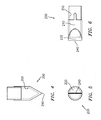
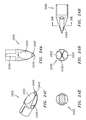
- Figures 4, 5 and 6 are side, end and top views, respectively, of the tip 200 of Figures 2 and 3 , including hidden lines illustrating internal surface geometry of the tip 200.
- any of the features described in connection with any of the following embodiments can advantageously be applied to this embodiment.
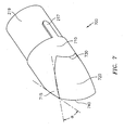
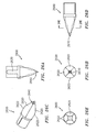
- Figures 7-11 illustrate an alternate embodiment of a penetrating tip 700 having an arcuate penetrating surface 740.
- the tip 700 includes a body 710, having at its proximal end a reduced-diameter portion 219, and one or more rotation locking elements 217.
- the tip 700 is manufactured integrally with a trocar, relative positioning can be achieved and maintained without such locking elements 217.
- the distal end of the penetrating tip 700 includes a distal taper 715 of the body 710, and two opposed angled facets 720, which are angled inwardly, approaching the cutting or dissecting edge 740 at the distal end of the tip 700.
- the facets 720 are delimited partially by an arcuate contour interface 730 with the body 210, and partially by the distal edge 740.
- the facets 720 are convexly contoured, rather than being planar, which can best be seen in the side view of Figure 9 .
- the facets 720 are angled, with respect to one another at an angle ⁇ (alpha).
- the angle ⁇ can be, for example, anywhere from about 5 degrees to about 80 degrees.
- FIG 8 is an isometric view of the tip 700 of Figure 7 , including hidden lines illustrating internal surface geometry of the tip 700.
- an internal surface 750 is formed within the tip 700, which includes surface features corresponding to features of the outer surface of the tip 700.
- any of the embodiments set forth herein can include a solid tip.
- such tip will include optical elements to enable adequate optical transmission of images from the distal end of the tip 700.
- an imaging device such as a CCD is provided within the body 710 of the tip 700 at an appropriate location, such as just proximal of the facet 720, an adequate image can be obtained regardless of the optical characteristics of the remainder of the tip 700.
- Figures 9-11 are side, end and top views of the tip 700 of Figures 7-8 , including hidden lines illustrating internal surface geometry. Naturally, any of the features described in connection with any other embodiment set forth herein can advantageously be applied to this embodiment.
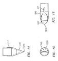
- FIGS 12-16 illustrate a further embodiment of a penetrating tip, designated generally with reference number 1200.
- the tip 1200 includes ovoid facets 1120 formed thereon, terminating in an arcuate cutting or dissecting surface 1240.
- the tip 1200 is similar in many respects to the foregoing embodiments.
- the ovoid facets 1220 result in a reduced profile for insertion. That is, instead of the relatively wide surfaces 240, 740 of the above-described tips 200, 700, respectively, the cutting or dissecting edge 1240, at the distal end of the ovoid facets 1220, is relatively narrow. This aspect of the tip 1200, can facilitate initial insertion by reducing the force necessary to puncture the abdominal wall.
- the tapered region 1215 of the body 1210 helps widen the initial incision, as the tip 1200 advances through the patient's abdominal wall.
- the ovoid facets 1220 can be convex or planar, as desired, and are delimited by the penetrating edge 1240, and the contour interface 1230, where the contour of the tip 1200 transitions from the facet 1220 to the relatively cylindrical body 1210.
- the facets 1220 are angled with respect to one another at an angle ⁇ (alpha).
- the angle ⁇ can be anywhere from about 5 degrees to about 80 degrees, for example.
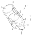
- Figure 13 is an isometric view of the tip 1200 of Figure 12 , including hidden lines illustrating internal surface geometry of the tip 1200.
- the internal surface 1350 of the tip 1200 is visible.
- the internal surface 1350 can include features that correspond to features of the outer surface of the tip 1200.
- the tip 1200 can include a contour interface 1353 corresponding to the contour interface 1230 of the outer surface of the tip 1200, and can include an inner facet 1352 corresponding to the facet 1220 on the outer surface of the tip 1200.
- Figures 14-16 are side, end and top views, respectively, of the tip of Figures 12-13 , including hidden lines illustrating internal surface geometry. Naturally, any of the features described in connection with any other embodiment set forth herein can advantageously be applied to this embodiment.
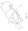
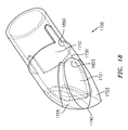
- Figure 17-21 illustrate another embodiment of a penetrating tip 1700 having multiple facets 1721, 1723, 1725 on each side thereof, including ovoid facets 1721, and terminating in an arcuate cutting or dissecting surface 1740, similar to the embodiment of Figures 7-11 .
- the penetrating tip 1700 includes a body 1710, at its proximal end having a reduced-diameter portion 219, and one or more rotation locking elements 217, as with the foregoing embodiments.
- the distal end of the penetrating tip 1700 includes a distal taper 1715 of the body 1710, and opposed angled facets 1721, 1723, 1725, which are angled inwardly, approaching the penetrating edge 1740 at the distal end of the penetrating tip 1700.
- the facets 1721, 1723, 1725 can be either convex or substantially planar. As illustrated, the facets include a substantially planar facet 1721, and convex facets 1723, 1725, the convexity of which is best seen, for example, in the side view of Figure 19 .
- the facets 1721, 1723, 1725 are delimited on one side by the contour interface 1730 and at the other side by the cutting or dissecting edge 1740.
- the change in contours among adjacent facets is defined therebetween at a contour interface indicated by line 1732.
- the facets 1721 of opposite sides of the penetrating tip 1700 are angled, with respect to one another at an angle ⁇ (alpha).
- the angle ⁇ can be anywhere from about 5 degrees to about 80 degrees, at any one degree increment therebetween, for example.
- the contour interface 1730 includes a corresponding inner contour interface 1853 defined on the inner surface 1850 of the tip 1700, as part of a generally corresponding overall shape.
- Figures 19-21 are side, end and top views, respectively of the tip 1700 of Figures 17 and 18 , including hidden lines illustrating internal surface geometry.
- Figures 22A-22F and 23A-D represent further embodiments of a tip 2200.
- Fig. 22A depicts a lengthwise view of tip 2200 along one of two opposing substantially ovoid main facets 2220 that converge to a distal dissecting edge 2210.
- facets 2220 are substantially flat, as opposed to concave or convex.
- Additional smaller facets 2225 are defined between the main facets 2220.
- the intervening facets 2225 are generally elongate concave formations or grooves. It will be appreciated that each of the facets 2220, 2225 may be substantially flat, convex or concave, as desired.
- Fig. 22B depicts an end view of tip 2200, showing the manner in which all four facets converge and taper to edge 2210.
- Fig. 22C depicts a lengthwise view of tip 2200 illustrating the shape of facet 2225.
- Fig. 22D illustrates a cross sectional view of tip 2200 taken along line "A-A" in Fig. 22C.
- Fig. 22E illustrates a cross sectional view of tip 2200 taken along line "B-B" in Fig. 22A.
- Fig. 22F illustrates an enlarged cross sectional view of tip 2200 illustrating a locking feature discussed below.
- Figs. 23A-C depict similar illustrations of tip 2200 showing the interior surfaces of tip 2200 in broken lines.
- Fig. 23D depicts an isometric view of tip 2200.
- tip 2200 defines a hollow interior 2250 bound by a plurality of inner surfaces 2260.
- a locking feature 2230 may be provided to facilitate attachment of tip 2200 to a trocar shaft, as described herein.
- the tip 2200 may be fully transparent or may include one or more opaque, darkened or otherwise visually obscured regions, such as in the distal region 240 of the tip 2200, proximate the dissecting edge 2210 in region 2240. Such regions are illustrated in the embodiments of Figs. 24-26 and discussed in further detail below, and can improve visibility of the anatomy being penetrated by reducing glare from stray light entering the tip 2200.
- the opaque distal region of the body can minimize glare by reducing errant internal reflections within the tip 2200.
- the opaque distal region which can be colored and in contrast with the remainder of the body of the penetrating tip, can be provided in a manner such that it functions as an indicator or gauge.
- the term opaque generally refers to an item that substantially inhibits transmission of light.
- the opaque distal region can be black, gray, blue, white, red, green, purple, pink, yellow, orange or any color desired.
- the tip can be translucent and can be clear or have a color imparted thereon.
- the degree of translucidity can be selected as desired, and thus may still act to reduce glare and/or to serve as a gauge or guide. It is also conceived that providing the entire tip or only the distal region 2240 of the tip 2200 with a particular color can serve to act as an optical filter to enhance images obtained therethrough.
- the colored or obscured distal region 2240 when the colored or obscured distal region 2240 is provided in a trocar used in a surgery, a patient's abdomen can be insufflated normally, and an endoscope inserted through the abdominal wall in a conventional manner. Then, when a trocar having a penetrating tip constructed in accordance with the invention is inserted through the abdominal wall, upon reaching the peritoneum, the distal region (having a color, or other feature), becomes readily visible to the surgeon. This is possible only if the surgeon views the procedure through the endoscope already inserted through the abdominal wall. This, however, may require two separate people to view two separate endoscopes.
- Figures 24A-24D depict an embodiment of a tip 2400 made in accordance with the present invention having a plurality of facets 2420, 2425 similar to the embodiment of Figs. 22-23 and defining a dissecting edge 2410. More particularly, facets 2420 are generally flat surfaces, and facets 2425 are generally concave grooves. Locking features 2430 are further provided to facilitate a connection with a trocar tube. Moreover, a distal region 2440 is provided that is generally pyramidal shaped to ease penetration in tissue. As depicted, the distal region 2440 is darkened, opaque or otherwise obscured, such as by a coating applied thereto, for example, or in another manner.
- Such an obscured or opaque region can help reduce the effects of internal reflections in the tip 2400, thus improving viewing.
- all tips disclosed herein may be provided with such an opaque, or otherwise obscured distal region, as desired.
- the opaque or obscured region may be made by depositing an opaque material on the surface of the tip 2400 in region 2440, such as by screen printing or painting.
- such a region may be provided by treating the surface of the tip to be obscured such as by roughening to substantially prevent light from passing through the region 2440.
- the obscured region 2440 can be separately formed of an opaque material and combined, by insert molding or other suitable manufacturing technique, with the remaining material of the tip 2400.
- the region 2440 may be treated by providing a second material within the material of the tip 2400 in the region 2440 in order to darken the region 2440.
- the tip 2400 is preferably hollow as with the foregoing embodiments, in order to ease image transmission and to accommodate an endoscope therein for transmitting and receiving light.
- Figs. 25A-25D illustrate another embodiment of a tip 2500 made in accordance with the invention.
- the tip 2500 includes two facets 2520 similar to the embodiments of Figs. 22-24 .
- Tip 2500 further includes a generally pyramidal distal region 2540 that is opaque or otherwise obscured.
- the distal region 2540 terminates in a tissue separating edge 2510 and locking feature 2530 as with other embodiments described herein.
- tip 2500 further includes two longitudinal depressions 2545 formed therein. Depressions 2545 may facilitate advancement of tip 2500 through tissue by lowering resistance.
- depressions 2545 may be obscured and/or provided with an opaque coating to improve the optical performance of tip 2500.
- the tip 2500 is preferably hollow to accommodate an endoscope, and can be provided with optical features to enhance images obtained therefrom.
- Figs. 26A-26E illustrate yet another embodiment of a tip 2600.
- Tip 2600 includes a plurality of facets 2620 (four identical facets, as depicted) that join each other at edges 2622 and taper to form a distal region 2640 terminating at a penetrating edge 2610. As depicted, distal region 2640 is obscured or opaque. A locking feature 2630 may further be provided, if desired.
- the cross section of tip 2600 closely resembles a rectangle with inwardly bowed sides. Such a geometry effectively forms four concave facets 2620 with a reduced cross sectional profile that can facilitate advancement of tip 2600 through tissue by lowering insertion resistance.
- Tip 2600 is preferably hollow to accommodate an endoscope.
- Images can be output from the aforementioned devices-that is in the penetrating tips or in the trocars, for example.
- the images can be displayed for the surgeon on a monitor arranged in a convenient location. If so-desired, a monitor can be provided at and integrated with the proximal end of the trocar itself, so as to enhance the perception and ergonomic aspects of in accordance with the invention. If so-equipped, the proximal end of the trocar can be configured so as to include one or more integral handles to facilitate gripping of the trocar by the surgeon.
- images can be automatically manipulated in real time by a computer, prior to display, so as to reduce or eliminate any distortion, color imbalance or other optical aberrations which may be present in the raw image output from the image sensor.
- Penetrating tips and trocars in accordance with the invention can be used to create an opening in an anatomical structure of a patient, such in the patient's abdominal wall.
- the opening can be used to provide access or any of a variety of instruments, such as, for example, a feeding tube.
- devices constructed in accordance with the invention will be used to insert surgical access devices, such as access ports and cannulas, which maintain the opening formed by a trocar and therefore provide easy access to a surgical cavity.
- surgical access devices such as access ports and cannulas, which maintain the opening formed by a trocar and therefore provide easy access to a surgical cavity.
- Access devices described in the aforementioned application include various types of seals to inhibit escape of insufflation gas from a patient's peritoneal cavity during a surgical procedure.
- devices constructed in accordance with the invention can be used to insert flexible access devices, such as those set forth in the application entitled “Elastically Deformable Surgical Access Device” U.S. Patent Application Serial Number 11/544,856, filed October 6, 2006 . If used with such elastically deformable surgical access devices, engagement elements can be provided on the trocar or the penetrating tip to enable engagement with such access device.
- a trocar having a tip in accordance with the invention is used to pierce the abdominal wall of the patient.
- the surgeon is able to view the tissue being penetrated by the penetrating tip through any of the aforementioned means, such as through a video monitor.
- a surgical access device as those described above, will be inserted simultaneously through the opening created by the trocar.
- the trocar with the penetrating tip is inserted through the access device such that the penetrating tip protrudes from the end of the access port, and the penetrating tip, surrounded by the access port, is inserted through the abdominal wall.
- a scalpel is used to make an incision through the skin, and the penetrating tip with the trocar and access port is inserted through the remaining layers of tissue into the abdominal wall. The trocar is then removed, leaving the surgical access device in place in order to carry out the prescribed surgical procedure.
Claims (11)
- Une pointe pénétrante pour un trocart chirurgical, la pointe pénétrante comprenant:un corps généralement transparent possédant des extrémités proximale et distale;un bord intégral (2410, 2510) disposé à l'extrémité distale du corps ;deux facettes opposées biseautées vers l'intérieur, en substance planes (2420 ; 2520) formées dans le corps, convergeant l'une vers l'autre à hauteur du bord intégral (2410 ; 2510) ;et, entre les facettes opposées biseautées vers l'intérieur, en substance planes (2420 ; 2520), deux facettes supplémentaires (2425 ; 2545) qui convergent et sont biseautées vers le bord intégral (2410 ; 2510),
dans laquellele corps comprend les deux facettes opposées biseautées vers l'intérieur et planes (2420 ; 2520) et les deux facettes supplémentaires (2425 ; 2545) et dans laquelle le corps comprend par ailleurs une partie en pointe distale de forme généralement pyramidale (2440 ; 2540 ; 2640) qui est opaque,caractérisée en ce que les deux facettes supplémentaires (2425 ; 2545) sont généralement des rainures concaves (2425) ou des dépressions longitudinales (2545). - La pointe pénétrante selon la revendication 1, la pointe comprenant par ailleurs une région au diamètre élargi pour engager un dispositif d'accès chirurgical.
- La pointe pénétrante selon l'une des revendications 1 ou 2, dans laquelle les facettes opposées (2402 ; 2520 ; 2620) sont disposées sur la pointe dans un angle d'environ 20 degrés l'une par rapport à l'autre.
- La pointe pénétrante selon l'une des revendications 1 ou 2, dans laquelle les facettes opposées (2420 ; 2520) sont disposées sur la pointe dans un angle d'environ 30 degrés l'une par rapport à l'autre.
- La pointe pénétrante selon l'une des revendications 1 à 4, dans laquelle le bord (2410 ; 2510) présente en substance une configuration droite.
- La pointe pénétrante selon l'une des revendications 1 à 4, dans laquelle le bord (2410 ; 2510) présente en substance une configuration arquée convexe.
- La pointe pénétrante selon l'une des revendications 1 à 6, dans laquelle le bord (2410 ; 2510 ; 2610) est choisi dans le groupe composé d'un bord de découpe, d'un bord de dissection et d'un bord émoussé.
- La pointe pénétrante selon l'une des revendications 1 à 7, dans laquelle un élément de verrouillage (2430 ; 2530) est prévu sur le corps pour engager un obturateur.
- La pointe pénétrante selon l'une des revendications 1 à 9, dans laquelle la pointe comprend par ailleurs une surface optique interne configurée de manière à minimiser la distorsion des images prises au travers de la pointe pénétrante.
- La pointe pénétrante selon l'une des revendications 1 à 9, dans laquelle la pointe est formée d'un matériau de plastique.
- La pointe pénétrante selon l'une des revendications 1 à 10, dans laquelle la pointe est formée d'un matériau de polycarbonate.
Priority Applications (1)
| Application Number | Priority Date | Filing Date | Title |
|---|---|---|---|
| EP12184667.9A EP2537477B1 (fr) | 2006-10-06 | 2007-10-05 | Trocart de visualisation |
Applications Claiming Priority (3)
| Application Number | Priority Date | Filing Date | Title |
|---|---|---|---|
| US85000606P | 2006-10-06 | 2006-10-06 | |
| US92392107P | 2007-04-17 | 2007-04-17 | |
| PCT/US2007/021387 WO2008045316A2 (fr) | 2006-10-06 | 2007-10-05 | Trocart de visualisation |
Related Child Applications (2)
| Application Number | Title | Priority Date | Filing Date |
|---|---|---|---|
| EP12184667.9A Division-Into EP2537477B1 (fr) | 2006-10-06 | 2007-10-05 | Trocart de visualisation |
| EP12184667.9A Division EP2537477B1 (fr) | 2006-10-06 | 2007-10-05 | Trocart de visualisation |
Publications (2)
| Publication Number | Publication Date |
|---|---|
| EP2068732A2 EP2068732A2 (fr) | 2009-06-17 |
| EP2068732B1 true EP2068732B1 (fr) | 2014-04-23 |
Family
ID=39134626
Family Applications (2)
| Application Number | Title | Priority Date | Filing Date |
|---|---|---|---|
| EP12184667.9A Active EP2537477B1 (fr) | 2006-10-06 | 2007-10-05 | Trocart de visualisation |
| EP07839288.3A Active EP2068732B1 (fr) | 2006-10-06 | 2007-10-05 | Trocart de visualisation |
Family Applications Before (1)
| Application Number | Title | Priority Date | Filing Date |
|---|---|---|---|
| EP12184667.9A Active EP2537477B1 (fr) | 2006-10-06 | 2007-10-05 | Trocart de visualisation |
Country Status (3)
| Country | Link |
|---|---|
| US (1) | US8317815B2 (fr) |
| EP (2) | EP2537477B1 (fr) |
| WO (1) | WO2008045316A2 (fr) |
Families Citing this family (60)
| Publication number | Priority date | Publication date | Assignee | Title |
|---|---|---|---|---|
| EP2428172B1 (fr) | 2001-09-24 | 2013-07-24 | Applied Medical Resources Corporation | Obturateur sans lame |
| DE60337002D1 (de) | 2002-05-16 | 2011-06-16 | Applied Med Resources | Obturator mit kegelspitze |
| US20070049945A1 (en) | 2002-05-31 | 2007-03-01 | Miller Larry J | Apparatus and methods to install, support and/or monitor performance of intraosseous devices |
| US10973545B2 (en) | 2002-05-31 | 2021-04-13 | Teleflex Life Sciences Limited | Powered drivers, intraosseous devices and methods to access bone marrow |
| US11298202B2 (en) | 2002-05-31 | 2022-04-12 | Teleflex Life Sciences Limited | Biopsy devices and related methods |
| IL165224A0 (en) | 2002-05-31 | 2005-12-18 | Vidacare Corp | Apparatus and method to access bone marrow |
| US8641715B2 (en) | 2002-05-31 | 2014-02-04 | Vidacare Corporation | Manual intraosseous device |
| US11337728B2 (en) | 2002-05-31 | 2022-05-24 | Teleflex Life Sciences Limited | Powered drivers, intraosseous devices and methods to access bone marrow |
| US8668698B2 (en) | 2002-05-31 | 2014-03-11 | Vidacare Corporation | Assembly for coupling powered driver with intraosseous device |
| US7854724B2 (en) | 2003-04-08 | 2010-12-21 | Surgiquest, Inc. | Trocar assembly with pneumatic sealing |
| US9504477B2 (en) | 2003-05-30 | 2016-11-29 | Vidacare LLC | Powered driver |
| JP2007516737A (ja) | 2003-10-03 | 2007-06-28 | アプライド メディカル リソーシーズ コーポレイション | 刃先なし光学栓子 |
| EP3431026B1 (fr) | 2004-06-29 | 2020-09-23 | Applied Medical Resources Corporation | Instrument chirurgical optique à insufflation |
| US7470230B2 (en) | 2005-03-31 | 2008-12-30 | Tyco Healthcare Group Lp | Optical obturator |
| EP2073728B1 (fr) * | 2006-09-12 | 2018-11-07 | Teleflex Medical Devices S.à.r.l. | Dispositif pour biopsie |
| US8944069B2 (en) | 2006-09-12 | 2015-02-03 | Vidacare Corporation | Assemblies for coupling intraosseous (IO) devices to powered drivers |
| EP3189787B1 (fr) | 2006-09-12 | 2019-01-09 | Teleflex Medical Devices S.à.r.l. | Plateaux pour opérations médicales et procédés associés |
| AU2007303069B2 (en) | 2006-10-06 | 2013-03-21 | Applied Medical Resources Corporation | Visual insufflation port |
| WO2008045316A2 (fr) | 2006-10-06 | 2008-04-17 | Surgiquest, Incorporated | Trocart de visualisation |
| AU2008202266B2 (en) * | 2007-06-01 | 2013-09-12 | Covidien Lp | Obturator tips |
| USD667954S1 (en) * | 2007-10-05 | 2012-09-25 | Surgiquest, Inc. | Visualization trocar |
| USD663838S1 (en) | 2007-10-05 | 2012-07-17 | Surgiquest, Inc. | Visualization trocar |
| EP2231233B1 (fr) | 2008-01-25 | 2016-03-30 | Applied Medical Resources Corporation | Système d'accès par gonflement |
| EP3335651B1 (fr) | 2008-09-29 | 2019-07-17 | Applied Medical Resources Corporation | Système de trocart de première entrée |
| EP2341849B1 (fr) | 2008-10-10 | 2019-12-18 | SurgiQuest, Incorporated | Système de recyclage amélioré de gaz dans des trocarts chirurgicaux avec étanchéité pneumatique |
| US10278728B2 (en) * | 2009-01-30 | 2019-05-07 | St. Jude Medical, Llc | Transapical mini-introducer hemostasis valve and punch |
| EP2419005B1 (fr) * | 2009-04-15 | 2014-11-19 | Koninklijke Philips N.V. | Aiguille avec des fibres intégrées dans les facettes coupantes du biseau |
| WO2011052129A1 (fr) * | 2009-10-27 | 2011-05-05 | パナソニック株式会社 | Caméra intra-orale |
| RU2540913C2 (ru) * | 2009-12-10 | 2015-02-10 | Алькон Рисерч, Лтд. | Многоточечный лазерный хирургический зонд с использованием фасетных оптических элементов |
| WO2011130399A1 (fr) * | 2010-04-13 | 2011-10-20 | Surgiquest, Incorporated | Trocart de visualisation |
| GB201016056D0 (en) * | 2010-09-24 | 2010-11-10 | Surgical Innovations Ltd | Trocar tip |
| WO2012122263A2 (fr) | 2011-03-08 | 2012-09-13 | Surgiquest, Inc. | Ensemble trocart avec étanchéité pneumatique |
| US9254148B2 (en) | 2011-05-02 | 2016-02-09 | Applied Medical Resources Corporation | Low-profile surgical universal access port |
| GB2492987A (en) * | 2011-07-19 | 2013-01-23 | Surgical Innovations Ltd | Optical trocar assembly |
| US8979867B2 (en) * | 2011-09-23 | 2015-03-17 | Gholam A. Peyman | Vitreous cutter |
| US9216067B2 (en) | 2011-09-23 | 2015-12-22 | Gholam A. Peyman | Vitreous cutter sleeve and a vitreous cutter system using the same |
| WO2013059289A1 (fr) * | 2011-10-17 | 2013-04-25 | Beaver-Visitec International (Us), Inc. | Procédé de marquage de l'œil d'un patient pour référence lors d'une procédure d'implantation d'une lentille torique, et dispositif associé |
| JP6073906B2 (ja) * | 2011-10-18 | 2017-02-01 | コヴィディエン リミテッド パートナーシップ | 光学トロカールシステム |
| US9693802B2 (en) * | 2012-06-06 | 2017-07-04 | Covidien Lp | Obturator tip with insufflation pathway |
| US9308128B2 (en) | 2013-01-08 | 2016-04-12 | Novartis Ag | Multi-spot laser probe with micro-structured faceted proximal surface |
| AU2014233486B2 (en) * | 2013-03-15 | 2018-11-15 | DePuy Synthes Products, Inc. | Viewing trocar with integrated prism for use with angled endoscope |
| WO2015175922A1 (fr) * | 2014-05-15 | 2015-11-19 | Smith & Nephew, Inc. | Fixation de greffon tissulaire à ajustement de tension |
| US9545264B2 (en) | 2014-06-06 | 2017-01-17 | Surgiquest, Inc. | Trocars and obturators |
| DE102014118575B4 (de) * | 2014-12-12 | 2016-10-06 | Carl Zeiss Meditec Ag | Chirurgisches Instrument |
| US9801656B2 (en) | 2015-01-30 | 2017-10-31 | Surgiquest, Inc. | Self-adjusting pneumatically sealed trocar |
| WO2016131016A2 (fr) | 2015-02-13 | 2016-08-18 | Scapa Flow, Llc | Système et procédé de placement d'un dispositif médical dans un os |
| US10117675B2 (en) * | 2015-07-28 | 2018-11-06 | Covidien Lp | Trocar tip protector |
| US20170056047A1 (en) * | 2015-09-02 | 2017-03-02 | MicroAire Surgical Instruments, LLC. | Endoscopic Surgical Devices and Other Surgical Devices |
| US20180147328A1 (en) * | 2015-09-02 | 2018-05-31 | MicroAire Surgical Instruments, LLC. | Endoscopic Surgical Devices and Other Surgical Devices and Methods of Making, Especially Using Polyarylamides, Polyetherimides, Polyether Ether Ketones, and Liquid Crystal Polymers |
| CN111329440B (zh) | 2016-08-17 | 2023-03-21 | 瑞邦治疗股份有限公司 | 具有近端安装的摄像机的套管 |
| EP3500194A4 (fr) * | 2016-08-17 | 2020-03-18 | Rebound Therapeutics Corporation | Canule avec caméra montée sur le côté proximal |
| US10105042B2 (en) * | 2016-08-17 | 2018-10-23 | Rebound Therapeutics Corporation | Cannula with proximally mounted camera |
| EP3600107B1 (fr) * | 2017-03-23 | 2022-03-23 | Medlogical Innovations Pty Ltd | Dispositif de thérapie laser interstitielle |
| US11832886B2 (en) | 2017-08-14 | 2023-12-05 | Circinus Medical Technology Llc | System and method using augmented reality with shape alignment for medical device placement |
| US10722111B2 (en) | 2018-03-13 | 2020-07-28 | Covidien Lp | Optical trocar assembly |
| US11020270B1 (en) | 2018-06-18 | 2021-06-01 | Gholam A. Peyman | Vitrectomy instrument and a system including the same |
| US10736659B2 (en) | 2018-10-23 | 2020-08-11 | Covidien Lp | Optical trocar assembly |
| AU2020225290A1 (en) * | 2019-02-22 | 2021-08-05 | Rebound Therapeutics Corporation | Cannula and obturator with a transparent tip with an opaque component |
| CN109771036B (zh) * | 2019-03-15 | 2021-10-29 | 上海电气集团股份有限公司 | 终端受动器装置 |
| US11357542B2 (en) | 2019-06-21 | 2022-06-14 | Covidien Lp | Valve assembly and retainer for surgical access assembly |
Family Cites Families (74)
| Publication number | Priority date | Publication date | Assignee | Title |
|---|---|---|---|---|
| NL250623A (fr) * | 1959-05-05 | |||
| FR84847E (fr) * | 1962-12-04 | 1965-07-26 | ||
| US3459189A (en) * | 1965-07-28 | 1969-08-05 | Brunswick Corp | Trocar catheter |
| US3556085A (en) * | 1968-02-26 | 1971-01-19 | Olympus Optical Co | Optical viewing instrument |
| DE2538758C3 (de) | 1975-08-30 | 1979-09-13 | Eberhard Dr.Med. 4500 Osnabrueck Regenbogen | Obturator für ein Rektosigmoidoskop |
| US4319563A (en) * | 1977-12-02 | 1982-03-16 | Olympus Optical Co., Ltd. | Endoscope with a smoothly curved distal end face |
| US4191191A (en) * | 1978-02-13 | 1980-03-04 | Auburn Robert M | Laproscopic trocar |
| DE2847561A1 (de) | 1978-11-02 | 1980-05-08 | Wolf Gmbh Richard | Vorrichtung zum messen von objektlaengen in koerperhoehlen unter beobachtung |
| DE3512602A1 (de) | 1985-04-06 | 1986-10-09 | Richard Wolf Gmbh, 7134 Knittlingen | Endoskop zur bestimmung von objektgroessen in hohlraeumen |
| GB8816033D0 (en) * | 1988-07-06 | 1988-08-10 | Ethicon Inc | Improved safety trocar |
| US5058603A (en) * | 1988-08-09 | 1991-10-22 | Asahi Kogaku Kogyo K.K. | Length-measuring device and reference color display device for color tone adjustment for use in combination with endoscope |
| US5057082A (en) * | 1988-11-04 | 1991-10-15 | Plastic Injectors, Inc. | Trocar assembly |
| US5122122A (en) * | 1989-11-22 | 1992-06-16 | Dexide, Incorporated | Locking trocar sleeve |
| IT1240639B (it) * | 1990-05-04 | 1993-12-17 | Francesco Pianetti | Ago trequarti per laparoscopia a punta tronco-conica filettata |
| US5159920A (en) * | 1990-06-18 | 1992-11-03 | Mentor Corporation | Scope and stent system |
| DE4133073A1 (de) | 1990-10-11 | 1992-04-16 | Effner Gmbh | Trokar |
| DE4035146A1 (de) * | 1990-11-06 | 1992-05-07 | Riek Siegfried | Instrument zum penetrieren von koerpergewebe |
| US5685820A (en) * | 1990-11-06 | 1997-11-11 | Partomed Medizintechnik Gmbh | Instrument for the penetration of body tissue |
| US5779728A (en) * | 1991-05-29 | 1998-07-14 | Origin Medsystems, Inc. | Method and inflatable chamber apparatus for separating layers of tissue |
| JP3012373B2 (ja) * | 1991-06-05 | 2000-02-21 | 旭光学工業株式会社 | 内視鏡の先端部 |
| US5290276A (en) * | 1992-02-06 | 1994-03-01 | Sewell Jr Frank | Rotatable laparoscopic puncturing instrument |
| US5256149A (en) * | 1992-02-14 | 1993-10-26 | Ethicon, Inc. | Trocar having transparent cannula and method of using |
| US5342383A (en) * | 1992-03-27 | 1994-08-30 | Thomas Medical Products, Inc. | Soft tip obturator |
| US5405328A (en) * | 1992-06-17 | 1995-04-11 | Minnesota Mining And Manufacturing Company | Trocar with replaceable obturator |
| GR930100244A (el) * | 1992-06-30 | 1994-02-28 | Ethicon Inc | Εύκαμπτο ενδοσκοπικό χειρουργικό στόμιο εισόδου. |
| US5385572A (en) * | 1992-11-12 | 1995-01-31 | Beowulf Holdings | Trocar for endoscopic surgery |
| US5562696A (en) * | 1992-11-12 | 1996-10-08 | Cordis Innovasive Systems, Inc. | Visualization trocar |
| US5334150A (en) * | 1992-11-17 | 1994-08-02 | Kaali Steven G | Visually directed trocar for laparoscopic surgical procedures and method of using same |
| US5391153A (en) * | 1993-04-09 | 1995-02-21 | Habley Medical Technology Corporation | Trocar with linear movement seal |
| US5441041A (en) * | 1993-09-13 | 1995-08-15 | United States Surgical Corporation | Optical trocar |
| US5690664A (en) * | 1993-09-13 | 1997-11-25 | United States Surgical Corporation | Trocar having movable blade |
| US5467762A (en) * | 1993-09-13 | 1995-11-21 | United States Surgical Corporation | Optical trocar |
| US5330437A (en) * | 1993-11-12 | 1994-07-19 | Ethicon Endo-Surgery | Self sealing flexible elastomeric valve and trocar assembly for incorporating same |
| US5720761A (en) * | 1993-11-16 | 1998-02-24 | Worldwide Optical Trocar Licensing Corp. | Visually directed trocar and method |
| US5609562A (en) * | 1993-11-16 | 1997-03-11 | Worldwide Optical Trocar Licensing Corporation | Visually directed trocar and method |
| DE4401237C2 (de) * | 1994-01-18 | 1997-06-05 | Ruesch Willy Ag | Trokarvorrichtung |
| US5445142A (en) * | 1994-03-15 | 1995-08-29 | Ethicon Endo-Surgery, Inc. | Surgical trocars having optical tips defining one or more viewing ports |
| US5545150A (en) * | 1994-05-06 | 1996-08-13 | Endoscopic Concepts, Inc. | Trocar |
| CA2149290C (fr) * | 1994-05-26 | 2006-07-18 | Carl T. Urban | Trocart optique |
| US5647840A (en) * | 1994-09-14 | 1997-07-15 | Circon Corporation | Endoscope having a distally heated distal lens |
| US5624459A (en) * | 1995-01-26 | 1997-04-29 | Symbiosis Corporation | Trocar having an improved cutting tip configuration |
| US5591192A (en) * | 1995-02-01 | 1997-01-07 | Ethicon Endo-Surgery, Inc. | Surgical penetration instrument including an imaging element |
| US5569292A (en) * | 1995-02-01 | 1996-10-29 | Ethicon Endo-Surgery, Inc. | Surgical penetration instrument with transparent blades and tip cover |
| US5569291A (en) * | 1995-02-01 | 1996-10-29 | Ethicon Endo-Surgery, Inc. | Surgical penetration and dissection instrument |
| US5607441A (en) * | 1995-03-24 | 1997-03-04 | Ethicon Endo-Surgery, Inc. | Surgical dissector |
| US5738628A (en) * | 1995-03-24 | 1998-04-14 | Ethicon Endo-Surgery, Inc. | Surgical dissector and method for its use |
| US5980549A (en) * | 1995-07-13 | 1999-11-09 | Origin Medsystems, Inc. | Tissue separation cannula with dissection probe and method |
| US5817062A (en) * | 1996-03-12 | 1998-10-06 | Heartport, Inc. | Trocar |
| US5824042A (en) * | 1996-04-05 | 1998-10-20 | Medtronic, Inc. | Endoluminal prostheses having position indicating markers |
| US5697913A (en) * | 1996-08-09 | 1997-12-16 | Ethicon Endo-Surgery, Inc. | Trocar including cannula with stepped region |
| US5817061A (en) * | 1997-05-16 | 1998-10-06 | Ethicon Endo-Surgery, Inc. | Trocar assembly |
| US6017356A (en) * | 1997-09-19 | 2000-01-25 | Ethicon Endo-Surgery Inc. | Method for using a trocar for penetration and skin incision |
| US6632197B2 (en) * | 1999-04-16 | 2003-10-14 | Thomas R. Lyon | Clear view cannula |
| DE19925324C1 (de) * | 1999-06-02 | 2001-01-25 | Winter & Ibe Olympus | Trokarhülse mit Duckbillventil |
| US6283948B1 (en) * | 1999-07-13 | 2001-09-04 | Ethicon, Inc. | Trocar obturator having grooved passageway |
| US6206823B1 (en) * | 1999-08-02 | 2001-03-27 | Ethicon Endo-Surgery, Inc. | Surgical instrument and method for endoscopic tissue dissection |
| USD443360S1 (en) * | 2000-03-22 | 2001-06-05 | Dexterity Surgical Inc. | Distal end of obturator for a trocar |
| US6471638B1 (en) * | 2000-04-28 | 2002-10-29 | Origin Medsystems, Inc. | Surgical apparatus |
| US6884253B1 (en) * | 2000-05-16 | 2005-04-26 | Taut, Inc. | Penetrating tip for trocar assembly |
| US8398666B2 (en) * | 2000-05-16 | 2013-03-19 | Teleflex Medical Incorporated | Penetrating tip for trocar assembly |
| CA2409230C (fr) * | 2000-05-16 | 2009-06-02 | Taut, Inc. | Embout penetrant pour assemblage de trocart |
| DE60141776D1 (de) * | 2000-05-31 | 2010-05-20 | Teleflex Medical Inc | Trokaranordnung |
| US6613063B1 (en) * | 2000-10-03 | 2003-09-02 | Daniel Hunsberger | Trocar assembly |
| US6835201B2 (en) * | 2001-03-15 | 2004-12-28 | Neosurg Technologies, Inc. | Trocar |
| EP2428172B1 (fr) * | 2001-09-24 | 2013-07-24 | Applied Medical Resources Corporation | Obturateur sans lame |
| US6939296B2 (en) * | 2001-10-17 | 2005-09-06 | Applied Medical Resources Corp. | Laparoscopic illumination apparatus and method |
| US6830578B2 (en) * | 2001-11-26 | 2004-12-14 | Neosurg Technologies, Inc. | Trocar |
| JP2003199755A (ja) * | 2001-12-28 | 2003-07-15 | Olympus Optical Co Ltd | 内視鏡下手術用トロッカー |
| JP4328835B2 (ja) * | 2002-02-15 | 2009-09-09 | テレフレックス・メディカル・インコーポレイテッド | 医療装置のためのアンカーアセンブリ |
| US6918871B2 (en) * | 2003-06-19 | 2005-07-19 | Ethicon Endo-Surgery, Inc. | Method for accessing cavity |
| US6960164B2 (en) * | 2003-08-01 | 2005-11-01 | Neosurg Technologies, Inc. | Obturator tip for a trocar |
| US8070767B2 (en) | 2005-01-28 | 2011-12-06 | Tyco Healthcare Group Lp | Optical penetrating adapter for surgical portal |
| US7470230B2 (en) | 2005-03-31 | 2008-12-30 | Tyco Healthcare Group Lp | Optical obturator |
| WO2008045316A2 (fr) | 2006-10-06 | 2008-04-17 | Surgiquest, Incorporated | Trocart de visualisation |
-
2007
- 2007-10-05 WO PCT/US2007/021387 patent/WO2008045316A2/fr active Application Filing
- 2007-10-05 US US11/973,123 patent/US8317815B2/en active Active
- 2007-10-05 EP EP12184667.9A patent/EP2537477B1/fr active Active
- 2007-10-05 EP EP07839288.3A patent/EP2068732B1/fr active Active
Also Published As
| Publication number | Publication date |
|---|---|
| US8317815B2 (en) | 2012-11-27 |
| EP2537477A1 (fr) | 2012-12-26 |
| US20080086160A1 (en) | 2008-04-10 |
| EP2068732A2 (fr) | 2009-06-17 |
| WO2008045316A3 (fr) | 2008-10-02 |
| EP2537477B1 (fr) | 2014-12-03 |
| WO2008045316A2 (fr) | 2008-04-17 |
Similar Documents
| Publication | Publication Date | Title |
|---|---|---|
| EP2068732B1 (fr) | Trocart de visualisation | |
| US11723689B2 (en) | First-entry trocar system | |
| US10064648B2 (en) | Optical penetrating adapter for surgical portal | |
| WO2011130399A1 (fr) | Trocart de visualisation | |
| EP3175804B1 (fr) | Instrument chirurgical optique à insufflation | |
| AU2006200776A1 (en) | Optical obturator | |
| AU2015210401A1 (en) | Insufflating optical surgical instrument | |
| AU2015201956B2 (en) | First-entry trocar system |
Legal Events
| Date | Code | Title | Description |
|---|---|---|---|
| PUAI | Public reference made under article 153(3) epc to a published international application that has entered the european phase |
Free format text: ORIGINAL CODE: 0009012 |
|
| 17P | Request for examination filed |
Effective date: 20090406 |
|
| AK | Designated contracting states |
Kind code of ref document: A2 Designated state(s): AT BE BG CH CY CZ DE DK EE ES FI FR GB GR HU IE IS IT LI LT LU LV MC MT NL PL PT RO SE SI SK TR |
|
| AX | Request for extension of the european patent |
Extension state: AL BA HR MK RS |
|
| DAX | Request for extension of the european patent (deleted) | ||
| 17Q | First examination report despatched |
Effective date: 20100917 |
|
| GRAP | Despatch of communication of intention to grant a patent |
Free format text: ORIGINAL CODE: EPIDOSNIGR1 |
|
| INTG | Intention to grant announced |
Effective date: 20131106 |
|
| GRAS | Grant fee paid |
Free format text: ORIGINAL CODE: EPIDOSNIGR3 |
|
| GRAA | (expected) grant |
Free format text: ORIGINAL CODE: 0009210 |
|
| AK | Designated contracting states |
Kind code of ref document: B1 Designated state(s): AT BE BG CH CY CZ DE DK EE ES FI FR GB GR HU IE IS IT LI LT LU LV MC MT NL PL PT RO SE SI SK TR |
|
| REG | Reference to a national code |
Ref country code: GB Ref legal event code: FG4D |
|
| REG | Reference to a national code |
Ref country code: CH Ref legal event code: EP |
|
| REG | Reference to a national code |
Ref country code: AT Ref legal event code: REF Ref document number: 663284 Country of ref document: AT Kind code of ref document: T Effective date: 20140515 |
|
| REG | Reference to a national code |
Ref country code: IE Ref legal event code: FG4D |
|
| REG | Reference to a national code |
Ref country code: DE Ref legal event code: R096 Ref document number: 602007036283 Country of ref document: DE Effective date: 20140605 |
|
| REG | Reference to a national code |
Ref country code: AT Ref legal event code: MK05 Ref document number: 663284 Country of ref document: AT Kind code of ref document: T Effective date: 20140423 |
|
| REG | Reference to a national code |
Ref country code: NL Ref legal event code: VDEP Effective date: 20140423 |
|
| REG | Reference to a national code |
Ref country code: LT Ref legal event code: MG4D |
|
| PG25 | Lapsed in a contracting state [announced via postgrant information from national office to epo] |
Ref country code: IS Free format text: LAPSE BECAUSE OF FAILURE TO SUBMIT A TRANSLATION OF THE DESCRIPTION OR TO PAY THE FEE WITHIN THE PRESCRIBED TIME-LIMIT Effective date: 20140823 Ref country code: BG Free format text: LAPSE BECAUSE OF FAILURE TO SUBMIT A TRANSLATION OF THE DESCRIPTION OR TO PAY THE FEE WITHIN THE PRESCRIBED TIME-LIMIT Effective date: 20140723 Ref country code: LT Free format text: LAPSE BECAUSE OF FAILURE TO SUBMIT A TRANSLATION OF THE DESCRIPTION OR TO PAY THE FEE WITHIN THE PRESCRIBED TIME-LIMIT Effective date: 20140423 Ref country code: NL Free format text: LAPSE BECAUSE OF FAILURE TO SUBMIT A TRANSLATION OF THE DESCRIPTION OR TO PAY THE FEE WITHIN THE PRESCRIBED TIME-LIMIT Effective date: 20140423 Ref country code: GR Free format text: LAPSE BECAUSE OF FAILURE TO SUBMIT A TRANSLATION OF THE DESCRIPTION OR TO PAY THE FEE WITHIN THE PRESCRIBED TIME-LIMIT Effective date: 20140724 Ref country code: FI Free format text: LAPSE BECAUSE OF FAILURE TO SUBMIT A TRANSLATION OF THE DESCRIPTION OR TO PAY THE FEE WITHIN THE PRESCRIBED TIME-LIMIT Effective date: 20140423 Ref country code: CY Free format text: LAPSE BECAUSE OF FAILURE TO SUBMIT A TRANSLATION OF THE DESCRIPTION OR TO PAY THE FEE WITHIN THE PRESCRIBED TIME-LIMIT Effective date: 20140423 |
|
| PG25 | Lapsed in a contracting state [announced via postgrant information from national office to epo] |
Ref country code: AT Free format text: LAPSE BECAUSE OF FAILURE TO SUBMIT A TRANSLATION OF THE DESCRIPTION OR TO PAY THE FEE WITHIN THE PRESCRIBED TIME-LIMIT Effective date: 20140423 Ref country code: SE Free format text: LAPSE BECAUSE OF FAILURE TO SUBMIT A TRANSLATION OF THE DESCRIPTION OR TO PAY THE FEE WITHIN THE PRESCRIBED TIME-LIMIT Effective date: 20140423 Ref country code: ES Free format text: LAPSE BECAUSE OF FAILURE TO SUBMIT A TRANSLATION OF THE DESCRIPTION OR TO PAY THE FEE WITHIN THE PRESCRIBED TIME-LIMIT Effective date: 20140423 Ref country code: PL Free format text: LAPSE BECAUSE OF FAILURE TO SUBMIT A TRANSLATION OF THE DESCRIPTION OR TO PAY THE FEE WITHIN THE PRESCRIBED TIME-LIMIT Effective date: 20140423 Ref country code: LV Free format text: LAPSE BECAUSE OF FAILURE TO SUBMIT A TRANSLATION OF THE DESCRIPTION OR TO PAY THE FEE WITHIN THE PRESCRIBED TIME-LIMIT Effective date: 20140423 |
|
| PG25 | Lapsed in a contracting state [announced via postgrant information from national office to epo] |
Ref country code: PT Free format text: LAPSE BECAUSE OF FAILURE TO SUBMIT A TRANSLATION OF THE DESCRIPTION OR TO PAY THE FEE WITHIN THE PRESCRIBED TIME-LIMIT Effective date: 20140825 |
|
| REG | Reference to a national code |
Ref country code: DE Ref legal event code: R097 Ref document number: 602007036283 Country of ref document: DE |
|
| PG25 | Lapsed in a contracting state [announced via postgrant information from national office to epo] |
Ref country code: DK Free format text: LAPSE BECAUSE OF FAILURE TO SUBMIT A TRANSLATION OF THE DESCRIPTION OR TO PAY THE FEE WITHIN THE PRESCRIBED TIME-LIMIT Effective date: 20140423 Ref country code: CZ Free format text: LAPSE BECAUSE OF FAILURE TO SUBMIT A TRANSLATION OF THE DESCRIPTION OR TO PAY THE FEE WITHIN THE PRESCRIBED TIME-LIMIT Effective date: 20140423 Ref country code: SK Free format text: LAPSE BECAUSE OF FAILURE TO SUBMIT A TRANSLATION OF THE DESCRIPTION OR TO PAY THE FEE WITHIN THE PRESCRIBED TIME-LIMIT Effective date: 20140423 Ref country code: EE Free format text: LAPSE BECAUSE OF FAILURE TO SUBMIT A TRANSLATION OF THE DESCRIPTION OR TO PAY THE FEE WITHIN THE PRESCRIBED TIME-LIMIT Effective date: 20140423 Ref country code: BE Free format text: LAPSE BECAUSE OF FAILURE TO SUBMIT A TRANSLATION OF THE DESCRIPTION OR TO PAY THE FEE WITHIN THE PRESCRIBED TIME-LIMIT Effective date: 20140423 Ref country code: RO Free format text: LAPSE BECAUSE OF FAILURE TO SUBMIT A TRANSLATION OF THE DESCRIPTION OR TO PAY THE FEE WITHIN THE PRESCRIBED TIME-LIMIT Effective date: 20140423 |
|
| PLBE | No opposition filed within time limit |
Free format text: ORIGINAL CODE: 0009261 |
|
| STAA | Information on the status of an ep patent application or granted ep patent |
Free format text: STATUS: NO OPPOSITION FILED WITHIN TIME LIMIT |
|
| PG25 | Lapsed in a contracting state [announced via postgrant information from national office to epo] |
Ref country code: IT Free format text: LAPSE BECAUSE OF FAILURE TO SUBMIT A TRANSLATION OF THE DESCRIPTION OR TO PAY THE FEE WITHIN THE PRESCRIBED TIME-LIMIT Effective date: 20140423 |
|
| 26N | No opposition filed |
Effective date: 20150126 |
|
| REG | Reference to a national code |
Ref country code: DE Ref legal event code: R097 Ref document number: 602007036283 Country of ref document: DE Effective date: 20150126 |
|
| PG25 | Lapsed in a contracting state [announced via postgrant information from national office to epo] |
Ref country code: MC Free format text: LAPSE BECAUSE OF FAILURE TO SUBMIT A TRANSLATION OF THE DESCRIPTION OR TO PAY THE FEE WITHIN THE PRESCRIBED TIME-LIMIT Effective date: 20140423 Ref country code: LU Free format text: LAPSE BECAUSE OF FAILURE TO SUBMIT A TRANSLATION OF THE DESCRIPTION OR TO PAY THE FEE WITHIN THE PRESCRIBED TIME-LIMIT Effective date: 20141005 |
|
| REG | Reference to a national code |
Ref country code: CH Ref legal event code: PL |
|
| REG | Reference to a national code |
Ref country code: IE Ref legal event code: MM4A |
|
| PG25 | Lapsed in a contracting state [announced via postgrant information from national office to epo] |
Ref country code: SI Free format text: LAPSE BECAUSE OF FAILURE TO SUBMIT A TRANSLATION OF THE DESCRIPTION OR TO PAY THE FEE WITHIN THE PRESCRIBED TIME-LIMIT Effective date: 20140423 Ref country code: LI Free format text: LAPSE BECAUSE OF NON-PAYMENT OF DUE FEES Effective date: 20141031 Ref country code: CH Free format text: LAPSE BECAUSE OF NON-PAYMENT OF DUE FEES Effective date: 20141031 |
|
| REG | Reference to a national code |
Ref country code: FR Ref legal event code: PLFP Year of fee payment: 9 |
|
| PG25 | Lapsed in a contracting state [announced via postgrant information from national office to epo] |
Ref country code: IE Free format text: LAPSE BECAUSE OF NON-PAYMENT OF DUE FEES Effective date: 20141005 |
|
| PG25 | Lapsed in a contracting state [announced via postgrant information from national office to epo] |
Ref country code: HU Free format text: LAPSE BECAUSE OF FAILURE TO SUBMIT A TRANSLATION OF THE DESCRIPTION OR TO PAY THE FEE WITHIN THE PRESCRIBED TIME-LIMIT; INVALID AB INITIO Effective date: 20071005 Ref country code: MT Free format text: LAPSE BECAUSE OF FAILURE TO SUBMIT A TRANSLATION OF THE DESCRIPTION OR TO PAY THE FEE WITHIN THE PRESCRIBED TIME-LIMIT Effective date: 20140423 Ref country code: TR Free format text: LAPSE BECAUSE OF FAILURE TO SUBMIT A TRANSLATION OF THE DESCRIPTION OR TO PAY THE FEE WITHIN THE PRESCRIBED TIME-LIMIT Effective date: 20140423 |
|
| REG | Reference to a national code |
Ref country code: FR Ref legal event code: PLFP Year of fee payment: 10 |
|
| REG | Reference to a national code |
Ref country code: FR Ref legal event code: PLFP Year of fee payment: 11 |
|
| REG | Reference to a national code |
Ref country code: FR Ref legal event code: PLFP Year of fee payment: 12 |
|
| PGFP | Annual fee paid to national office [announced via postgrant information from national office to epo] |
Ref country code: GB Payment date: 20231027 Year of fee payment: 17 |
|
| PGFP | Annual fee paid to national office [announced via postgrant information from national office to epo] |
Ref country code: FR Payment date: 20231025 Year of fee payment: 17 Ref country code: DE Payment date: 20231027 Year of fee payment: 17 |