EP2068046A2 - Schaltpositionserkennungsvorrichtung für Gangwahlmechanismus eines Fahrezeuggetriebes - Google Patents
Schaltpositionserkennungsvorrichtung für Gangwahlmechanismus eines Fahrezeuggetriebes Download PDFInfo
- Publication number
- EP2068046A2 EP2068046A2 EP08019682A EP08019682A EP2068046A2 EP 2068046 A2 EP2068046 A2 EP 2068046A2 EP 08019682 A EP08019682 A EP 08019682A EP 08019682 A EP08019682 A EP 08019682A EP 2068046 A2 EP2068046 A2 EP 2068046A2
- Authority
- EP
- European Patent Office
- Prior art keywords
- shift
- gear
- shifting
- establishing
- load
- Prior art date
- Legal status (The legal status is an assumption and is not a legal conclusion. Google has not performed a legal analysis and makes no representation as to the accuracy of the status listed.)
- Granted
Links
Images



Classifications
-
- F—MECHANICAL ENGINEERING; LIGHTING; HEATING; WEAPONS; BLASTING
- F16—ENGINEERING ELEMENTS AND UNITS; GENERAL MEASURES FOR PRODUCING AND MAINTAINING EFFECTIVE FUNCTIONING OF MACHINES OR INSTALLATIONS; THERMAL INSULATION IN GENERAL
- F16H—GEARING
- F16H61/00—Control functions within control units of change-speed- or reversing-gearings for conveying rotary motion ; Control of exclusively fluid gearing, friction gearing, gearings with endless flexible members or other particular types of gearing
- F16H61/68—Control functions within control units of change-speed- or reversing-gearings for conveying rotary motion ; Control of exclusively fluid gearing, friction gearing, gearings with endless flexible members or other particular types of gearing specially adapted for stepped gearings
- F16H61/684—Control functions within control units of change-speed- or reversing-gearings for conveying rotary motion ; Control of exclusively fluid gearing, friction gearing, gearings with endless flexible members or other particular types of gearing specially adapted for stepped gearings without interruption of drive
- F16H61/688—Control functions within control units of change-speed- or reversing-gearings for conveying rotary motion ; Control of exclusively fluid gearing, friction gearing, gearings with endless flexible members or other particular types of gearing specially adapted for stepped gearings without interruption of drive with two inputs, e.g. selection of one of two torque-flow paths by clutches
-
- F—MECHANICAL ENGINEERING; LIGHTING; HEATING; WEAPONS; BLASTING
- F16—ENGINEERING ELEMENTS AND UNITS; GENERAL MEASURES FOR PRODUCING AND MAINTAINING EFFECTIVE FUNCTIONING OF MACHINES OR INSTALLATIONS; THERMAL INSULATION IN GENERAL
- F16H—GEARING
- F16H59/00—Control inputs to control units of change-speed- or reversing-gearings for conveying rotary motion
- F16H59/68—Inputs being a function of gearing status
-
- F—MECHANICAL ENGINEERING; LIGHTING; HEATING; WEAPONS; BLASTING
- F16—ENGINEERING ELEMENTS AND UNITS; GENERAL MEASURES FOR PRODUCING AND MAINTAINING EFFECTIVE FUNCTIONING OF MACHINES OR INSTALLATIONS; THERMAL INSULATION IN GENERAL
- F16H—GEARING
- F16H61/00—Control functions within control units of change-speed- or reversing-gearings for conveying rotary motion ; Control of exclusively fluid gearing, friction gearing, gearings with endless flexible members or other particular types of gearing
- F16H61/26—Generation or transmission of movements for final actuating mechanisms
- F16H61/28—Generation or transmission of movements for final actuating mechanisms with at least one movement of the final actuating mechanism being caused by a non-mechanical force, e.g. power-assisted
-
- F—MECHANICAL ENGINEERING; LIGHTING; HEATING; WEAPONS; BLASTING
- F16—ENGINEERING ELEMENTS AND UNITS; GENERAL MEASURES FOR PRODUCING AND MAINTAINING EFFECTIVE FUNCTIONING OF MACHINES OR INSTALLATIONS; THERMAL INSULATION IN GENERAL
- F16H—GEARING
- F16H59/00—Control inputs to control units of change-speed- or reversing-gearings for conveying rotary motion
- F16H59/68—Inputs being a function of gearing status
- F16H2059/6807—Status of gear-change operation, e.g. clutch fully engaged
-
- F—MECHANICAL ENGINEERING; LIGHTING; HEATING; WEAPONS; BLASTING
- F16—ENGINEERING ELEMENTS AND UNITS; GENERAL MEASURES FOR PRODUCING AND MAINTAINING EFFECTIVE FUNCTIONING OF MACHINES OR INSTALLATIONS; THERMAL INSULATION IN GENERAL
- F16H—GEARING
- F16H61/00—Control functions within control units of change-speed- or reversing-gearings for conveying rotary motion ; Control of exclusively fluid gearing, friction gearing, gearings with endless flexible members or other particular types of gearing
- F16H61/26—Generation or transmission of movements for final actuating mechanisms
- F16H61/28—Generation or transmission of movements for final actuating mechanisms with at least one movement of the final actuating mechanism being caused by a non-mechanical force, e.g. power-assisted
- F16H2061/2823—Controlling actuator force way characteristic, i.e. controlling force or movement depending on the actuator position, e.g. for adapting force to synchronisation and engagement of gear clutch
-
- F—MECHANICAL ENGINEERING; LIGHTING; HEATING; WEAPONS; BLASTING
- F16—ENGINEERING ELEMENTS AND UNITS; GENERAL MEASURES FOR PRODUCING AND MAINTAINING EFFECTIVE FUNCTIONING OF MACHINES OR INSTALLATIONS; THERMAL INSULATION IN GENERAL
- F16H—GEARING
- F16H2306/00—Shifting
- F16H2306/18—Preparing coupling or engaging of future gear
-
- F—MECHANICAL ENGINEERING; LIGHTING; HEATING; WEAPONS; BLASTING
- F16—ENGINEERING ELEMENTS AND UNITS; GENERAL MEASURES FOR PRODUCING AND MAINTAINING EFFECTIVE FUNCTIONING OF MACHINES OR INSTALLATIONS; THERMAL INSULATION IN GENERAL
- F16H—GEARING
- F16H2306/00—Shifting
- F16H2306/40—Shifting activities
- F16H2306/50—Coupling of new gear
-
- Y—GENERAL TAGGING OF NEW TECHNOLOGICAL DEVELOPMENTS; GENERAL TAGGING OF CROSS-SECTIONAL TECHNOLOGIES SPANNING OVER SEVERAL SECTIONS OF THE IPC; TECHNICAL SUBJECTS COVERED BY FORMER USPC CROSS-REFERENCE ART COLLECTIONS [XRACs] AND DIGESTS
- Y10—TECHNICAL SUBJECTS COVERED BY FORMER USPC
- Y10T—TECHNICAL SUBJECTS COVERED BY FORMER US CLASSIFICATION
- Y10T74/00—Machine element or mechanism
- Y10T74/19—Gearing
- Y10T74/19219—Interchangeably locked
- Y10T74/19251—Control mechanism
Definitions
- the present invention relates in general to shift position detecting devices for automotive transmissions and more particularly to the shift position detecting devices of a type that is suitable for detecting the shift position taken by a gear selection mechanism employed in automatic-manual transmissions (AMT) or the like.
- AMT automatic-manual transmissions
- speeds (or gear rows) provided by the transmission are classified into a plurality of speed groups, and each speed group is provided with a clutch for inputting an engine rotation individually.
- the classified speed groups are two groups that comprise odd number speeds and even number speeds.
- a synchronizing coupling mechanism for the speed group that includes the first speed is shifted (or pre-shifted) by a shift actuator from a neutral position to a first speed selection position (viz., first speed shift gear-in establishing position) keeping the clutches of both speed groups disengaged, and then the clutch for the speed group that includes the first speed is engaged.
- first speed selection position viz., first speed shift gear-in establishing position
- a synchronizing coupling mechanism for the speed group that includes the second speed is shifted (or pre-shifted) by a corresponding shift actuator from a neutral position to a second speed selection position (viz., second speed shift gear-in establishing position). That is, the pre-shifting to the first speed and the pre-shifting to the second speed are carried out simultaneously.
- the clutch for the speed group that includes the second speed is controlled to start its engaging operation, and when the engaging operation of the clutch is advanced by a certain degree, the clutch for the speed group that includes the first speed is disengaged, so that the speed change from the first speed to the second speed is carried out by the switching control for the two clutches.
- a synchronizing coupling mechanism for the speed group that includes the third speed is shifted (or pre-shifted) by a corresponding shift actuator from a neutral position to a third speed selection position (viz., third speed shift gear-in establishing position). That is, a pre-shifting to the third speed is carried out.
- the clutch for the speed group that includes the third speed is controlled to start its engaging operation, and when the engaging operation of the clutch is advanced by a certain degree, the clutch for the speed group that includes the second speed is disengaged, so that the speed change from the second speed to the third speed is carried out by the switching control for the two clutches.
- a synchronizing coupling mechanism for the speed group that includes the fourth speed is shifted (or pre-shifted) by a corresponding shift actuator from a neutral position to a fourth speed selection position (viz., fourth speed shift gear-in establishing position). That is, a pre-shifting to the fourth speed is carried out.
- Similar but reversed switching control for two clutches and similar pre-shifting are carried out. That is, by making similar switching control for two clutches and similar pre-shifting, a predetermined down-shifting for speeds is carried out.
- the above-mentioned Laid-open Patent Application discloses a shift position detecting device of magnetically coupled type which comprises a permanent magnet that moves together with the synchronizing coupling mechanism and a magnetic sensor that senses a magnetic flux produced by the permanent magnet.
- the shift position detecting device shown by the publication needs a skilled technique for assembling the device and mounting the device to a given position of the transmission, which causes increase in cost of the transmission. If the device is inaccurately assembled and/or inaccurately mounted to the transmission, satisfied performance of the device is not expected.
- One measure may be thought out for solving the above-mentioned shortcomings. That is, in the measure, with the work of the corresponding shift actuator, the synchronizing coupling mechanism is shifted to the shift gear-in establishing position, and an output data issued from the magnetic sensor when the synchronizing coupling mechanism comes to the shift gear-in establishing position is taken as a sign (or information data) for completion of shifting of the coupling mechanism to the shift gear-in establishing position.
- various output data are obtained for respective shift positions, and a data map is provided that shows a relation between the output data and the shift positions. With reference to the data map, a shift position can be looked up from a certain output data.
- the degree of warping of the magnet holding structure differs or varies depending on the individual difference of each transmission.
- a warping of the magnet holding structure which is inevitably induced when a gear selection mechanism is shifted to a shift gear-in establishing position, has no effect on detecting exact shift position, and correlation of the shift gear-in establishing position of the gear selection mechanism with the output data issued from the magnetic sensor when the synchronizing coupling mechanism comes to such establishing position is accurately provided.
- a shift position detecting device for use in an automotive transmission having a gear selection mechanism for each gear train, the gear selection mechanism being shifted to a shift gear-in establishing position by a corresponding shift actuator thereby to select the gear train as a power transmission gear train.
- the position detecting device comprises a shift position sensor that continuously issues an output data that represents a shift position of the gear selection mechanism; and a control unit which includes a first shifting load instruction section that controls the shift actuator to shift the gear selection mechanism to the shift gear-in establishing position with a first shifting load; a second shifting load instruction section that, after completion of shifting of the gear selection mechanism to the shift gear-in establishing position by the first shifting load instruction section, controls the shift actuator to reduce the shifting load from the first shifting load to a second shifting load which is lower than the first shifting load; and a shift gear-in establishing position memory section that stores an output data issued from the shift position sensor when the shift actuator is controlled by the second shifting load instruction section, as an information data that represents completion of shifting of the gear selection mechanism to the shift gear-in establishing position.
- a method of detecting a shift gear-in establishing position in an automotive transmission including a gear selection mechanism for each gear train, the gear selection mechanism being shifted to the shift gear-in establishing position by a corresponding shift actuator thereby to select the gear train as a power transmission gear train, and a shift position sensor that continuously issues an output data that represents a shift position of the gear selection mechanism.
- the method comprises controlling the shift actuator to shift the gear selection mechanism to the shift gear-in establishing position with a first shifting load; after completion of shifting of the gear selection mechanism to the shift gear-in establishing position by the first shifting load, controlling the shift actuator to reduce the shifting load from the first shifting load to a second shifting load which is lower than the first shifting load; and storing an output data issued from the shift position sensor when the shift actuator is controlled by the second shifting load, as an information data that represents completion of shifting of the gear selection mechanism to the shift gear-in establishing position.
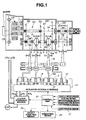
- FIG. 1 there is shown a twin clutch automatic-manual transmission with a speed change control system, to which a shift position detecting device of a first embodiment of the present invention is practically applied.
- twin clutch automatic-manual transmission and the speed change control system shown in Fig. 1 are substantially same in mechanical construction as those shown in the above-mentioned Japanese Laid-open Patent Application (Tokkai) 2007-040407 . Thus, detailed description of the mechanical construction will be omitted in the following description.
- a coupling sleeve 2 of a synchronizing coupling mechanism (or gear selection mechanism) 1 for the first speed is shifted leftward (in Fig. 1 ) by a shift actuator 3 from a neutral position as shown in the drawing to a first speed selection position (viz., first shift gear-in establishing position) keeping the released condition of the two clutches CA and CB.
- a first speed output gear 4 is brought into engagement with a countershaft 5 thereby to select a first speed transmission gear train.
- the clutch CA of the speed group that includes the first speed is engaged to practically establish the first speed transmission gear train. That is, the first speed is established in the transmission.
- a coupling sleeve 7 of a synchronizing coupling mechanism (or gear selection mechanism) 6 for the second speed is shifted leftward (in Fig. 1 ) by a shift actuator 8 from a neutral position as shown in the drawing to a second speed selection position (viz., second speed shift gear-in establishing position), so that a second speed output gear 9 is brought into engagement with the counter shaft 5 thereby to select a second speed transmission gear train. That is, during the above-mentioned time, a pre-shifting to the second speed is carried out.
- the clutch CB for the speed group that includes the second speed is controlled to start its engaging operation, and when the engaging operation of the clutch CB is advanced by a certain degree, the clutch CA for the speed group that includes the first speed is disengaged or released, so that the speed change from the first speed to the second speed is carried out by the switching action between the two clutches CA and CB.
- a coupling sleeve 11 of a synchronizing coupling mechanism (or gear selection mechanism) 10 for the third speed is shifted leftward (in Fig. 1 ) by a shift actuator 12 from a neutral position as shown in the drawing to a third speed selection position (viz., third speed shift gear-in establishing position), a third speed input gear 13 is brought into engagement with a corresponding input shaft 14 thereby to select a third speed transmission gear train. That is, a pre-shifting to the third speed is carried out.
- the clutch CB for the speed group that includes the third speed is controlled to start its engaging opening, and when the engaging operation of the clutch CB is advanced by a certain degree, the clutch CA for the speed group that includes the second speed is disengaged or released, so that the speed change from the second speed to the third speed is carried out by the switching action between the two clutches CA and CB. That is, switching of transmission gear trains is carried out from the second speed to the third speed.
- coupling sleeve 7 of synchronizing coupling mechanism (or gear selection mechanism) 6 for the fourth speed is shifted back by shift actuator 8 from the second speed selection position (viz., second speed shift gear-in establishing position) to the neutral position as shown in the drawing, and then coupling sleeve 7 is shifted rightward in the drawing from the neutral position to a fourth speed selection position (viz., fourth speed shift gear-in establishing position).
- a fourth speed output gear 15 is brought into engagement with countershaft 5 thereby to select a fourth speed transmission gear train. That is, a pre-shifting to the fourth speed is carried out.
- Similar but reversed switching control for the two clutches CA and CB and similar pre-shifting are carried out. That is, by making similar switching control for the two clutches CA and CB and similar pre-shifting, desired down-shifting is carried out.
- coupling sleeve 2 of synchronizing coupling mechanism (or gear selection mechanism) 1 for the reverse is shifted (or pre-shifted) rightward by shift actuator 3 from the neutral position as shown in the drawing to a reverse selection position (or reverse shift gear-in establishing position) keeping the released condition of the two clutches CA and CB.
- a reverse output gear 16 is brought into engagement with countershaft 5 thereby to select a reverse transmission gear train.
- clutch CA of the speed group that includes the reverse is engaged to practically establish the reverse transmission gear train. That is, reverse mode of the transmission is established and thus the vehicle runs backward.
- a shift position sensor 17 of magnetically coupled type which comprises a permanent magnet 17a (see Fig. 2 ) that moves together with coupling sleeve (2) and a magnetic sensor 17b that is fixed to a fixed portion of the transmission to sense a magnetic flux produced by permanent magnet 17a.
- shift actuators 3, 8 and 12 For carrying out the above-mentioned speed change shifting, operation of shift actuators 3, 8 and 12 (or shifting operation of synchronizing coupling mechanisms 1, 6 and 10) is controlled in the following manner by a control unit 21 through an actuator hydraulic module 22. It is to be noted that, in Fig. 1 , a shift actuator 26 is further shown, which is used for establishing the sixth speed transmission gear train.
- control unit 21 When, for staring the vehicle, the pre-shifting to the first speed from the neutral position is detected, control unit 21 issues an instruction signal to an actuator hydraulic module 22, for the purpose of shifting coupling sleeve 2 leftward from the neutral position as shown in Fig. 1 to the first speed selection position (or first speed shift gear-in establishing position).
- the detection of pre-shifting to the first speed can be made by a movement of a shift lever of the transmission and/or various information signals fed to control unit 21.
- the information signals fed to control unit 21 are those issued from a vehicle speed sensor, an accelerator pedal depressing degree sensor, a range position sensor and other sensors and switches.
- actuator hydraulic module 22 Upon receiving such instruction signal, actuator hydraulic module 22 controls shift actuator 3 so that coupling sleeve 2 is shifted (or pre-shifted) to the first speed selection position (or first speed shift gear-in establishing position).
- shift actuator 3 shifts or moves coupling sleeve 2 to the first speed selection position (or first speed shift gear-in establishing position). That is, requested pre-shifting to the first speed is achieved.
- control unit 21 judges that synchronizing coupling mechanism (or gear selection mechanism) 1 for the first speed has arrived at the first speed selection position (viz., first speed shift gear-in establishing position) and thus judges that the pre-shifting to the first speed has been finished.
- control unit 21 issues an instruction signal to actuator hydraulic module 22 for making the actuating pressure of shift actuator 3 zero.
- a shift force of shift actuator 3 for pressing coupling sleeve 2 to the first speed selection position (or first speed shift gear-in establishing position) becomes zero finishing the pre-shifting control for the first speed.
- control unit 21 When, for reverse running, the pre-shifting to the reverse from the neutral position is detected, control unit 21 issues an instruction signal to actuator hydraulic module 22, for the purpose of shifting coupling sleeve 2 rightward from the neutral position as shown in Fig. 1 to the reverse selection position (or reverse shift gear-in establishing position).
- actuator hydraulic module 22 Upon receiving such instruction signal, actuator hydraulic module 22 controls shift actuator 3 so that coupling sleeve 2 is shifted (or pre-shifted) to the reverse selection position (or reverse shift gear-in establishing position).
- shift actuator 3 shifts or moves coupling sleeve 2 to the reverse selection position (or reverse shift gear-in establishing position). That is, requested pre-shifting to the reverse is achieved.
- control unit 21 judges that synchronizing coupling mechanism (or gear selection mechanism) 1 for the reverse has arrived at the reverse selection position (viz., reverse shift gear-in establishing position) and thus judges that the pre-shifting to the reverse has finished.
- control unit 21 issues an instruction signal to actuator hydraulic module 22 for making the actuating pressure of shift actuator 3 zero.
- the pre-shifting load produced by shift actuator 3 is used for shifting coupling sleeve 2 to a desired one of the shift gear-in establishing positions.
- the pre-shifting load should be controlled or determined to a minimum but practical degree.
- the following measure is employed for satisfying the above-mentioned control for the pre-shifting load.
- an initial value of the pre-shifting load is set, for example, to 200N, that is, an almost minimum value that makes the pre-shifting possible at ordinary temperature, and with such initial minimum pre-shifting load, shifting of coupling sleeve 2 to a desired shift gear-in establishing position is tried.
- coupling sleeve 2 is returned back to the neutral position, and the pre-shifting load is increased by a certain degree (for example, 100N) from the initial value, and then, with such once increased pre-shifting load, the shifting of coupling sleeve 2 to the shift gear-in establishing position is tried again.
- a certain degree for example, 100N
- the pre-shifting load can be controlled to a minimum value that enables coupling sleeve 2 to completely reach the desired shift gear-in establishing position.
- the pre-shifting load is not unnecessarily large, and thus, the durability of the 1-R synchronizing coupling mechanism is not decreased and undesired noise or vibration is not produced or at least minimized even when coupling sleeve 2 is shifted to the desired shift gear-in establishing position.
- the minimum and practical value of the pre-shifting load becomes high as the temperature of the hydraulic fluid of the transmission lowers.
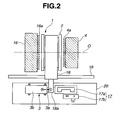
- 1-R synchronizing coupling mechanism (or gear selection mechanism) 1 is arranged to surround countershaft 5 that rotates about an axis "O" (see Fig. 2 ) thereof.
- the synchronizing coupling mechanism 1 includes a coupling sleeve 2 that is able to move axially in both rightward and leftward directions in the drawing.
- coupling sleeve 2 is arranged between first speed output gear 4 and reverse output gear 16 that are rotatably disposed about countershaft 5. It is to be noted that for ease of understanding, the positional relation of the two gears 4 and 16 shown in Fig. 2 is reversed relative to that shown in Fig. 1 .
- first speed output gear 4 is formed with clutch gear teeth 4a
- reverse output gear 16 is formed with clutch gear teeth 16a.
- shift fork 18 is slidably moved on and along a shift rod 19 by shift actuator 3.
- Shift rod 19 is installed in a transmission case to extend along the direction in which shift fork 18 moves.
- Shift actuator 3 has an actuating rod 3a connected to a shifter 18a that radially outward projects from shift fork 18.
- Shift actuator 3 is of a hydraulic reciprocating type including mutually engaged piston and cylinder. As shown in Fig. 2 , shift actuator 3 is mounted to a mounting plate 20 fixed to the transmission case. For this mounting, an actuator body 3b of shift actuator 3 that includes the piston and cylinder is fixed to mounting plate 20.
- actuating rod 3a makes a straight movement in one of the directions indicated by arrows.
- coupling sleeve 2 is moved toward a given position through shifter 18a and shift fork 18. That is, when coupling sleeve 2 is moved rightward, the above-mentioned first speed transmission gear train is selected, while when coupling sleeve 2 is moved leftward, the above-mentioned reverse transmission gear train is selected. That is, upon operation of shift actuator 3, coupling sleeve 2 is shifted to the first speed shift gear-in establishing position or the reverse shift gear-in establishing position.
- the shift position sensor 17 In order to detect the position taken by coupling sleeve 2 that is absolutely needed for carrying out the pre-shifting for the first speed or the pre-shifting for the reverse, the shift position sensor 17 is employed, which has the following construction.
- shift position sensor 17 comprises a permanent magnet 17a that is mounted to shifter 18a to move therewith and a magnetic sensor 17b that is secured to a given portion of mounting plate 20 for sensing a magnetic flux produced by permanent magnet 17a. That is, by sensing a change of the magnetic flux produced by magnet 17a, the sensor 17b detects a displacement of permanent magnet 17a relative to the sensor 17b with the aid of a known control unit. Actually, by the control unit, the magnetic signal sensed by the magnetometric sensor 17b is conversed to a potential signal.
- Magnetic sensor 17b minutely detects the displacement of permanent magnet 17a (or position of coupling sleeve 2), and outputs a potential value that varies continuously in accordance with the detected displacement of permanent magnet 17a.
- the shift position of coupling sleeve 2 and the output data issued from the sensor 17b are proportional to each other. Accordingly, by processing the output data of the sensor 17b, the shift position of coupling sleeve 2 can be derived.
- control unit 21 for solving such drawback, the following process is carried out by control unit 21 in the first embodiment of the invention.
- coupling sleeve 2 is shifted to the rightmost position in Fig. 2 by shift actuator 3, that is, the position (or first speed shift gear-in establishing position) where coupling sleeve 2 fully or deeply abuts against clutch gear teeth 4a of first speed output gear 4, and output data issued from shift position sensor 17 when coupling sleeve 2 comes to the rightmost position is treated as a decided data that represents completion of shifting of coupling sleeve 2 to the first speed shift gear-in establishing position.
- shift actuator 3 that is, the position (or first speed shift gear-in establishing position) where coupling sleeve 2 fully or deeply abuts against clutch gear teeth 4a of first speed output gear 4
- output data issued from shift position sensor 17 when coupling sleeve 2 comes to the rightmost position is treated as a decided data that represents completion of shifting of coupling sleeve 2 to the first speed shift gear-in establishing position.
- coupling sleeve 2 is shifted to the leftmost position in Fig. 2 by shift actuator, that is, the position (or reverse shift gear-in establishing position) where coupling sleeve 2 fully or deeply abuts against clutch gear teeth 16a of reverse output gear 16, and the output data issued from shift position sensor 17 when coupling sleeve 2 comes to the leftmost position is treated as an information data that represents completion of shifting of coupling sleeve 2 to the reverse shift gear-in establishing position.
- shift actuator that is, the position (or reverse shift gear-in establishing position) where coupling sleeve 2 fully or deeply abuts against clutch gear teeth 16a of reverse output gear 16
- the output data issued from shift position sensor 17 when coupling sleeve 2 comes to the leftmost position is treated as an information data that represents completion of shifting of coupling sleeve 2 to the reverse shift gear-in establishing position.
- control unit 21 carries out a calibration for making a data map that indicates a relation between the output data and the shift positions. With reference to the data map, the shift position is looked up from a certain output data.
- Fig. 3 is a data map showing the relation between the output data issued from shift position sensor 17 and the shift position taken by coupling sleeve 2. That is, the vertical axis represents the shift position of coupling sleeve 2 and the horizontal axis represents the output data issued from shift position sensor 17.
- the output data issued from shift position sensor 17 is enforced to have a value that is larger than the maximum value "Vmax" by a degree that corresponds to the warping of the magnet supporting structure (18, 18a).
- the output data issued from shift position sensor 17 is enforced to have a value that is smaller than the minimum value "Vmin" by a degree that corresponds to the warping of the magnet supporting structure (18, 18a).
- the degree of warping of the magnet supporting structure (18, 18a) varies depending on the individual difference of each transmission.
- the warping of the magnet supporting structure (18, 18a), which is inevitably induced when coupling sleeve 2 is shifted to the shift gear-in establishing position, has no effect on finding correct information data that represents completion of shifting of coupling sleeve 2 to the shift gear-in establishing position.
- Fig. 4 is a time chart showing a control for correlating the shift gear-in establishing position with an output data issued from shift position sensor, during the time from “t1" to "t3" for which the first speed shift gear-in establishing time " ⁇ T1" is passing, the shifting load produced by shift actuator 3 is increased to a first shifting load (viz., shift gear-in load) and then the shifting load is kept at the first shifting load.
- a first shifting load viz., shift gear-in load
- the first shifting load has a value (or load) that assures the shifting of coupling sleeve 2 to the shift gear-in establishing position even if the transmission is in frigid temperatures.
- the value is about 1000N.
- the first speed shift gear-in establishing time " ⁇ T1" is a time needed for assuredly shifting coupling sleeve 2 from the neutral position to the first shift gear-in establishing position
- the first shifting load viz., shift gear-in load
- the first shifting load is a sufficiently large load needed for assuredly shifting coupling sleeve 2 from the neutral position to the first shift gear-in establishing position.
- the second shifting load is set to a predetermined low value that does not induce the warping of the magnet supporting structure (18, 18a).
- the second shifting load has a value that induces a smaller warping of the shift transfer portion (18, 18a) that does not affect the output data issued from shift position sensor 17.
- shift actuator 3 lowers the actuating force applied to shift fork 18 and thus the warping of the magnet supporting structure (18, 18a) becomes zero.
- the output data of shift position sensor 17 lowers and at the time "T4" when the time lag " ⁇ T2" is completed, the output data from the sensor 17 shows a value that corresponds to the first speed shift gear-in establishing position.
- the second shifting load is set to the low load that does not induce the warping of the magnet supporting structure (18, 18a).
- such second shifting load may be set to a vary small load that induces only a very small warping of the magnet supporting structure (18, 18a).
- the shifting load produced by shift actuator 3 is controlled to be sharply lowered from the first shifting load to the second shifting load.
- such lowering of the shifting load to the second shifting load may be slowly carried out.
- the shifting load established when the output data from shift position sensor 17 does not lower any longer may be used as the second shifting load.
- the output data kept issued from shift position sensor 17 during the time from the time "t5" to the time “t6" are averaged to obtain a mean value and the mean value thus obtained is memorized or stored as an information data that represents completion of shifting of coupling sleeve 2 to the first speed shift gear-in establishing position.
- the mean value is used for making the above-mentioned data map.
- control unit 21 (see Fig. 1 ) comprises generally a first shifting load instruction section, a second shifting load instruction section and a shift gear-in establishing position memory section.
- the output data issued from shift position sensor 17 when coupling sleeve 2 is shifted to the shift gear-in establishing position by shift actuator 3 is not directly used as the information data.
- the shifting load applied to coupling sleeve 2 from shift actuator 3 is lowered from the first shifting load (viz., the shift gear-in load needed for shifting coupling sleeve 2 to the shift gear-in establishing position) to the second shifting load that is lower than the first shifting load, and the output data issued from shift position sensor 17 when the shifting load is lowered to the second shift load is memorized or stored as an information data that represents completion of shifting of coupling sleeve 2 to the shift gear-in establishing position.
- the data map when a data map is produced by practically using the correlation between the shift position and the shift position sensor output data, the data map can avoid influence caused by the above-mentioned warping of the magnet supporting structure (18, 18a). That is, the data map thus made can be much practically used.
- the second shifting load is set to a value that induces zero (0) of the warping of the magnet supporting structure (18, 18a)
- the influence by the warping of the magnet supporting structure (18, 18a) is completely avoided.
- the correlation between the shift gear-in establishing portion for coupling sleeve 2 and the output data issued from shift position sensor 17 is much more practically provided.
- the output data issued from shift position sensor 17 from the time "t5" when the time “ ⁇ T3" passes from the time “t3” is memorized or stored as an information data that represents completion of shifting of coupling sleeve 2 to the shift gear-in establishing position. Accordingly, errors that would appear in the output data of shift position sensor 17 during the time " ⁇ T2" for which the warping of the shift transfer portion (18, 18a) is kept remained can be assuredly avoided.
- the output data issued from shift position sensor 17 are read and averaged to obtain a mean value, and the mean value is memorized or stored as an information data that represents completion of coupling sleeve 2 to the shift gear-in establishing position. Accordingly, even when some of the output data of shift position sensor 17 are subjected to electric fluctuation, such fluctuation is appropriately absorbed. Thus, the correlation between the shift gear-in establishing position of coupling sleeve 2 and the output data issued from shift position sensor 17 is much more practically provided.
- the second embodiment will be described with reference to a time chart of Fig. 5 .
- the shifting load produced by shift actuator 3 is increased to the first shift load (viz., shift gear-in load) and then the shifting load is kept at the first shifting load.
- the shifting load produced by shift actuator 3 is sharply lowered from the first shifting load to a lowest load (for example, 0 (zero) in the illustrated example) that is lower than the above-mentioned second shifting load, and then the shifting load is kept at the lowest load.
- a lowest load for example, 0 (zero) in the illustrated example
- coupling sleeve 2 can be shifted to the first speed shift gear-in establishing position without inducing the warping of the magnet supporting structure (18, 18a).
- the output data of shift position sensor 17 increases with a certain time lag " ⁇ T7" in a manner as is shown in the time chart of Fig. 5 , and at the time “t6" when the time lag" ⁇ T7" is completed, the output data of shift position sensor 17 indicates a value that corresponds to the first speed shift gear-in establishing position.
- the output data kept issued from shift position sensor 17 during the time " ⁇ T4" are averaged to obtain a mean value and the mean value thus obtained is memorized or stored as an information data that represents completion of shifting of coupling sleeve 2 to the first speed shift gear-in establishing position.
- the mean value is used for making the above-mentioned data map.
- the output data that is issued from shift position sensor 17 when coupling sleeve 2 is shifted to the shift gear-in establishing position by shift actuator 3 is not directly used as the information data.
- the output data that is issued from shift position sensor 17 when the shifting load is lowered to the second shift load that does not induce the warping of the magnet supporting structure (18, 18a) is memorized or stored as an information data that represents completion of shifting of coupling sleeve 2 to the shift gear-in establishing position.
- the influence of the warping that would appear when coupling sleeve 2 is shifted to the shift gear-in establishing position can be avoided or at least minimized, and thus the correlation between the shift gear-in establishing position for coupling sleeve 2 and the output data issued from shift position sensor 17 is much more practically provided.
- a data map that is produced by practically using the shift position sensor output data with reference to the shift position of coupling sleeve 2 can avoid influence from the above-mentioned warping of the magnet supporting structure (18, 18a). That is, the data map thus made can be much practically used.
- shift actuator 3 is controlled to produce the lowest load (viz., zero load), which is lower than the second shifting load, before being controlled to produce the second shifting load.
- shift actuator 3 is controlled to produce the second shifting load from a condition wherein shift actuator 3 is controlled to produce the zero loading.
- the output data of shift position sensor 17 issued after the time “t7" when the time “ ⁇ T8" has passed from the time “t5" are used as data that corresponds to the shift gear-in establishing position for coupling sleeve 2. Accordingly, an error that would be produced during the time " ⁇ T7” does not affect the output data of shift position sensor 17.
- the correlation between the shift gear-in establishing position for coupling sleeve 2 and the output data issued from shift position sensor 17 when coupling sleeve 2 takes the shift gear-in establishing position is much ore practically provided.
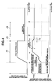
- control unit 21 makes such a control as is depicted by the graph of Fig. 6 .
- a first speed shifting operation for shifting coupling sleeve 2 to the first speed shift gear-in establishing position and a reverse shifting operation for shifting coupling sleeve 2 to the reverse shift gear-in establishing position are repeatedly and alternately carried out at a predetermined period " ⁇ T9".
- the mean value of the output data issued from shift position sensor 17 during the time " ⁇ T4" that is, the mean values "Vmax1” “Vmax2”, “Vmax3”” of the output data issued when coupling sleeve 2 takes the first speed shift gear-in establishing position and the mean values "Vmin1”, “Vmin2”, “Vmin3”,,,,,of the output data issued when coupling sleeve 2 takes the reverse shift gear-in establishing position are obtained.
- the maximum one is memorized or stored as an information data that represents completion of shifting of coupling sleeve 2 to the first speed shift gear-in establishing position
- the mean values "Vmin1”, “Vmin2”, “Vmin3”, the minimum one is memorized or stored as an information data that represents completion of shifting of coupling sleeve 2 to the reverse shift gear-in establishing position.
- the correlation between the shift gear-in establishing position of coupling sleeve 2 and the output data issued from shift position sensor 17 may be updated at the following frequency.
- the associated motor vehicle If the associated motor vehicle is just shipped, it is preferable to update the shift gear-in establishing position at predetermined intervals of ignition-on switching operation of an associated automotive engine.
- the predetermined intervals are varied depending on operation time, travel distance, and number of ignition-on switching operation.
- an indicating means 23 is provided as is shown in Fig. 1 .
- control unit 21 operates the indicating means 23 letting the driver know that the correlation is being treated.
- a select inhibiting means 24 is provided as is shown in Fig. 1 .
- the control unit 21 operates the select inhibiting means 24.
- select inhibiting means 24 actual manual switching from the non-drive range to the drive range is not carried out even if the driver makes a select operation from the non-drive range to the drive range.
Landscapes
- Engineering & Computer Science (AREA)
- General Engineering & Computer Science (AREA)
- Mechanical Engineering (AREA)
- Control Of Transmission Device (AREA)
- Gear-Shifting Mechanisms (AREA)
Applications Claiming Priority (2)
| Application Number | Priority Date | Filing Date | Title |
|---|---|---|---|
| JP2007314397 | 2007-12-05 | ||
| JP2008184356A JP5125839B2 (ja) | 2007-12-05 | 2008-07-16 | 変速機用選択噛合機構のシフト位置検出装置 |
Publications (3)
| Publication Number | Publication Date |
|---|---|
| EP2068046A2 true EP2068046A2 (de) | 2009-06-10 |
| EP2068046A3 EP2068046A3 (de) | 2011-09-14 |
| EP2068046B1 EP2068046B1 (de) | 2012-08-29 |
Family
ID=40394356
Family Applications (1)
| Application Number | Title | Priority Date | Filing Date |
|---|---|---|---|
| EP08019682A Active EP2068046B1 (de) | 2007-12-05 | 2008-11-11 | Fahrzeuggetriebe |
Country Status (2)
| Country | Link |
|---|---|
| US (1) | US8224543B2 (de) |
| EP (1) | EP2068046B1 (de) |
Cited By (1)
| Publication number | Priority date | Publication date | Assignee | Title |
|---|---|---|---|---|
| WO2013068175A1 (de) * | 2011-11-11 | 2013-05-16 | Zf Friedrichshafen Ag | Verfahren zur steuerung von schaltabläufen eines getriebes |
Families Citing this family (5)
| Publication number | Priority date | Publication date | Assignee | Title |
|---|---|---|---|---|
| DE102012005675A1 (de) * | 2012-03-21 | 2013-09-26 | Daimler Ag | Kraftfahrzeugantriebsstrangvorrichtung mit einem Mehrgruppengetriebe |
| US9097507B2 (en) * | 2013-06-19 | 2015-08-04 | Honeywell International Inc. | Non-contact shift lever position detector and health status monitoring system |
| SE541436C2 (en) * | 2016-12-21 | 2019-10-01 | Scania Cv Ab | A method and a system for controlling a synchromesh arrangement |
| CN110576860B (zh) * | 2018-11-22 | 2020-11-20 | 长城汽车股份有限公司 | 车辆、减速器挡位探测的控制方法和装置 |
| JP7099410B2 (ja) | 2019-06-28 | 2022-07-12 | トヨタ自動車株式会社 | 同期噛合機構の制御装置 |
Citations (2)
| Publication number | Priority date | Publication date | Assignee | Title |
|---|---|---|---|---|
| JP2007040407A (ja) | 2005-08-03 | 2007-02-15 | Nissan Motor Co Ltd | 自動マニュアルトランスミッションのシフト位置検出装置 |
| JP2008184356A (ja) | 2007-01-30 | 2008-08-14 | Taiheiyo Cement Corp | セメント組成物 |
Family Cites Families (4)
| Publication number | Priority date | Publication date | Assignee | Title |
|---|---|---|---|---|
| US5743143A (en) * | 1996-08-09 | 1998-04-28 | Eaton Corporation | Transmission shifting mechanism and position sensor |
| US6067495A (en) * | 1997-06-24 | 2000-05-23 | Chrysler Corporation | Acceleration based shift strategy for an automatic transmission |
| EP1506359A2 (de) * | 2002-05-10 | 2005-02-16 | LuK Lamellen und Kupplungsbau Beteiligungs KG | Verfahren und vorrichtung zum betrieb insbesondere eines automatischen bzw. automatisierten getriebes mit parksperre bzw. wegrollsicherung |
| JP4970753B2 (ja) | 2005-08-03 | 2012-07-11 | 日産自動車株式会社 | 自動マニュアルトランスミッションの変速制御装置 |
-
2008
- 2008-11-07 US US12/267,148 patent/US8224543B2/en active Active
- 2008-11-11 EP EP08019682A patent/EP2068046B1/de active Active
Patent Citations (2)
| Publication number | Priority date | Publication date | Assignee | Title |
|---|---|---|---|---|
| JP2007040407A (ja) | 2005-08-03 | 2007-02-15 | Nissan Motor Co Ltd | 自動マニュアルトランスミッションのシフト位置検出装置 |
| JP2008184356A (ja) | 2007-01-30 | 2008-08-14 | Taiheiyo Cement Corp | セメント組成物 |
Cited By (1)
| Publication number | Priority date | Publication date | Assignee | Title |
|---|---|---|---|---|
| WO2013068175A1 (de) * | 2011-11-11 | 2013-05-16 | Zf Friedrichshafen Ag | Verfahren zur steuerung von schaltabläufen eines getriebes |
Also Published As
| Publication number | Publication date |
|---|---|
| US8224543B2 (en) | 2012-07-17 |
| EP2068046A3 (de) | 2011-09-14 |
| EP2068046B1 (de) | 2012-08-29 |
| US20090150033A1 (en) | 2009-06-11 |
Similar Documents
| Publication | Publication Date | Title |
|---|---|---|
| JP5771637B2 (ja) | 変速機用ギヤ締結装置 | |
| EP1750037B1 (de) | Schaltpositionssensor eines automatisierten Getriebes | |
| EP2068046B1 (de) | Fahrzeuggetriebe | |
| CN101451611B (zh) | 车辆变速器的档位选择机构的换档移动位置检测装置 | |
| EP1120589B1 (de) | Schalt- bzw. Wählvorrichtung für ein automatisiertes Schaltgetriebe | |
| JP3738740B2 (ja) | ツインクラッチ式歯車変速機 | |
| US8556772B2 (en) | Manual transmission clutch protection apparatus | |
| US7878084B2 (en) | Method for determining the position of a shifting element | |
| CN201539552U (zh) | 双离合器自动变速器换挡机构的位置检测系统 | |
| EP1837560B1 (de) | Automatisiertes Handschaltgetriebe und Verfahren zu seiner Steuerung | |
| WO2004097266A1 (en) | Drive transmission | |
| CN101603588A (zh) | 双离合器自动变速器换档机构的位置检测方法及系统 | |
| EP2151609B1 (de) | Doppelkupplungsgetriebe | |
| EP2653753B1 (de) | Steuerungsvorrichtung für ein doppelkupplungsgetriebe und steuerverfahren für ein doppelkupplungsgetriebe | |
| CN102829174A (zh) | 用于手动变速器的预测挡位感应系统 | |
| EP1798452B1 (de) | Automatikgetriebe, Steuervorrichtung und Verfahren dafür | |
| US10344850B2 (en) | Shift control apparatus of automatic transmission | |
| JP6016599B2 (ja) | 自動変速機のシフト操作装置 | |
| US9810317B2 (en) | Method for controlling driving of vehicle | |
| EP2151595A1 (de) | Vorrichtung zur Kupplungssteuerung | |
| JP2013194893A (ja) | 自動変速機の制御装置 | |
| EP1184607A1 (de) | Steuerungseinrichtung einer Stelleinrichtung für den Einsatz in einer Getriebeeinheit | |
| US6397696B2 (en) | Automatic gear transmission | |
| GB2491885A (en) | A method and system for improving gear change quality | |
| JP6108885B2 (ja) | 自動変速機のシフト操作装置 |
Legal Events
| Date | Code | Title | Description |
|---|---|---|---|
| PUAI | Public reference made under article 153(3) epc to a published international application that has entered the european phase |
Free format text: ORIGINAL CODE: 0009012 |
|
| 17P | Request for examination filed |
Effective date: 20081111 |
|
| AK | Designated contracting states |
Kind code of ref document: A2 Designated state(s): AT BE BG CH CY CZ DE DK EE ES FI FR GB GR HR HU IE IS IT LI LT LU LV MC MT NL NO PL PT RO SE SI SK TR |
|
| AX | Request for extension of the european patent |
Extension state: AL BA MK RS |
|
| PUAL | Search report despatched |
Free format text: ORIGINAL CODE: 0009013 |
|
| AK | Designated contracting states |
Kind code of ref document: A3 Designated state(s): AT BE BG CH CY CZ DE DK EE ES FI FR GB GR HR HU IE IS IT LI LT LU LV MC MT NL NO PL PT RO SE SI SK TR |
|
| AX | Request for extension of the european patent |
Extension state: AL BA MK RS |
|
| RIC1 | Information provided on ipc code assigned before grant |
Ipc: F16H 61/688 20060101AFI20110808BHEP |
|
| GRAP | Despatch of communication of intention to grant a patent |
Free format text: ORIGINAL CODE: EPIDOSNIGR1 |
|
| RIC1 | Information provided on ipc code assigned before grant |
Ipc: F16H 61/688 20060101AFI20120131BHEP Ipc: F16H 59/68 20060101ALN20120131BHEP Ipc: F16H 61/28 20060101ALN20120131BHEP |
|
| RTI1 | Title (correction) |
Free format text: AUTOMOTIVE TRANSMISSION |
|
| AKX | Designation fees paid |
Designated state(s): DE FR GB |
|
| GRAS | Grant fee paid |
Free format text: ORIGINAL CODE: EPIDOSNIGR3 |
|
| GRAA | (expected) grant |
Free format text: ORIGINAL CODE: 0009210 |
|
| AK | Designated contracting states |
Kind code of ref document: B1 Designated state(s): DE FR GB |
|
| REG | Reference to a national code |
Ref country code: GB Ref legal event code: FG4D |
|
| REG | Reference to a national code |
Ref country code: DE Ref legal event code: R096 Ref document number: 602008018316 Country of ref document: DE Effective date: 20121025 |
|
| PLBE | No opposition filed within time limit |
Free format text: ORIGINAL CODE: 0009261 |
|
| STAA | Information on the status of an ep patent application or granted ep patent |
Free format text: STATUS: NO OPPOSITION FILED WITHIN TIME LIMIT |
|
| 26N | No opposition filed |
Effective date: 20130530 |
|
| REG | Reference to a national code |
Ref country code: DE Ref legal event code: R097 Ref document number: 602008018316 Country of ref document: DE Effective date: 20130530 |
|
| REG | Reference to a national code |
Ref country code: FR Ref legal event code: PLFP Year of fee payment: 8 |
|
| REG | Reference to a national code |
Ref country code: FR Ref legal event code: PLFP Year of fee payment: 9 |
|
| REG | Reference to a national code |
Ref country code: FR Ref legal event code: PLFP Year of fee payment: 10 |
|
| REG | Reference to a national code |
Ref country code: FR Ref legal event code: PLFP Year of fee payment: 11 |
|
| PGFP | Annual fee paid to national office [announced via postgrant information from national office to epo] |
Ref country code: DE Payment date: 20251022 Year of fee payment: 18 |
|
| PGFP | Annual fee paid to national office [announced via postgrant information from national office to epo] |
Ref country code: GB Payment date: 20251023 Year of fee payment: 18 |
|
| PGFP | Annual fee paid to national office [announced via postgrant information from national office to epo] |
Ref country code: FR Payment date: 20251022 Year of fee payment: 18 |