EP2068040B1 - Gear and connection device using the gear - Google Patents
Gear and connection device using the gear Download PDFInfo
- Publication number
- EP2068040B1 EP2068040B1 EP07745269A EP07745269A EP2068040B1 EP 2068040 B1 EP2068040 B1 EP 2068040B1 EP 07745269 A EP07745269 A EP 07745269A EP 07745269 A EP07745269 A EP 07745269A EP 2068040 B1 EP2068040 B1 EP 2068040B1
- Authority
- EP
- European Patent Office
- Prior art keywords
- gear
- tooth
- shape
- tooth member
- face
- Prior art date
- Legal status (The legal status is an assumption and is not a legal conclusion. Google has not performed a legal analysis and makes no representation as to the accuracy of the status listed.)
- Expired - Fee Related
Links
Images


Classifications
-
- F—MECHANICAL ENGINEERING; LIGHTING; HEATING; WEAPONS; BLASTING
- F16—ENGINEERING ELEMENTS AND UNITS; GENERAL MEASURES FOR PRODUCING AND MAINTAINING EFFECTIVE FUNCTIONING OF MACHINES OR INSTALLATIONS; THERMAL INSULATION IN GENERAL
- F16H—GEARING
- F16H55/00—Elements with teeth or friction surfaces for conveying motion; Worms, pulleys or sheaves for gearing mechanisms
- F16H55/02—Toothed members; Worms
- F16H55/08—Profiling
-
- B—PERFORMING OPERATIONS; TRANSPORTING
- B60—VEHICLES IN GENERAL
- B60N—SEATS SPECIALLY ADAPTED FOR VEHICLES; VEHICLE PASSENGER ACCOMMODATION NOT OTHERWISE PROVIDED FOR
- B60N2/00—Seats specially adapted for vehicles; Arrangement or mounting of seats in vehicles
- B60N2/02—Seats specially adapted for vehicles; Arrangement or mounting of seats in vehicles the seat or part thereof being movable, e.g. adjustable
- B60N2/22—Seats specially adapted for vehicles; Arrangement or mounting of seats in vehicles the seat or part thereof being movable, e.g. adjustable the back-rest being adjustable
- B60N2/225—Seats specially adapted for vehicles; Arrangement or mounting of seats in vehicles the seat or part thereof being movable, e.g. adjustable the back-rest being adjustable by cycloidal or planetary mechanisms
- B60N2/2252—Seats specially adapted for vehicles; Arrangement or mounting of seats in vehicles the seat or part thereof being movable, e.g. adjustable the back-rest being adjustable by cycloidal or planetary mechanisms in which the central axis of the gearing lies inside the periphery of an orbital gear, e.g. one gear without sun gear
-
- B—PERFORMING OPERATIONS; TRANSPORTING
- B60—VEHICLES IN GENERAL
- B60N—SEATS SPECIALLY ADAPTED FOR VEHICLES; VEHICLE PASSENGER ACCOMMODATION NOT OTHERWISE PROVIDED FOR
- B60N2/00—Seats specially adapted for vehicles; Arrangement or mounting of seats in vehicles
- B60N2/02—Seats specially adapted for vehicles; Arrangement or mounting of seats in vehicles the seat or part thereof being movable, e.g. adjustable
- B60N2/22—Seats specially adapted for vehicles; Arrangement or mounting of seats in vehicles the seat or part thereof being movable, e.g. adjustable the back-rest being adjustable
- B60N2/225—Seats specially adapted for vehicles; Arrangement or mounting of seats in vehicles the seat or part thereof being movable, e.g. adjustable the back-rest being adjustable by cycloidal or planetary mechanisms
- B60N2/2254—Seats specially adapted for vehicles; Arrangement or mounting of seats in vehicles the seat or part thereof being movable, e.g. adjustable the back-rest being adjustable by cycloidal or planetary mechanisms provided with braking systems
-
- F—MECHANICAL ENGINEERING; LIGHTING; HEATING; WEAPONS; BLASTING
- F16—ENGINEERING ELEMENTS AND UNITS; GENERAL MEASURES FOR PRODUCING AND MAINTAINING EFFECTIVE FUNCTIONING OF MACHINES OR INSTALLATIONS; THERMAL INSULATION IN GENERAL
- F16H—GEARING
- F16H1/00—Toothed gearings for conveying rotary motion
- F16H1/28—Toothed gearings for conveying rotary motion with gears having orbital motion
- F16H1/32—Toothed gearings for conveying rotary motion with gears having orbital motion in which the central axis of the gearing lies inside the periphery of an orbital gear
-
- Y—GENERAL TAGGING OF NEW TECHNOLOGICAL DEVELOPMENTS; GENERAL TAGGING OF CROSS-SECTIONAL TECHNOLOGIES SPANNING OVER SEVERAL SECTIONS OF THE IPC; TECHNICAL SUBJECTS COVERED BY FORMER USPC CROSS-REFERENCE ART COLLECTIONS [XRACs] AND DIGESTS
- Y10—TECHNICAL SUBJECTS COVERED BY FORMER USPC
- Y10T—TECHNICAL SUBJECTS COVERED BY FORMER US CLASSIFICATION
- Y10T74/00—Machine element or mechanism
- Y10T74/19—Gearing
- Y10T74/19949—Teeth
- Y10T74/19963—Spur
- Y10T74/19972—Spur form
- Y10T74/19986—Twisted
Definitions
- the present invention relates to gears and a coupling apparatus using the gears. More specifically, the present invention relates to gears constituting a gear train provided in a state of meshing with each other for enabling transmission of a power.
- JP-A-2005-83535 discloses a specific constitution of the above-described reclining apparatus corresponding to the preamble of claim 1.
- an outer gear is disposed in a state of meshing with an inner gear, and the backrest angle of the seat back is varied by a relative revolving movement of the outer gear along an inner peripheral tooth face of the inner gear.
- a tooth shape of the above-described inner gear or outer gear is formed to have a shape of a cycloid curve or a trochoid curve.
- a meshing line of the two gears is set to a shape of a circular arc, and therefore, in comparison with a gear train of a publicly-known tooth shape having an involute curve resulting a linear meshing line, a meshing strength can be increased by the increase in the meshing rate.
- the meshing line of the gear train can be set to the shape of the circular arc, the meshing rate can be adjusted only within a limited narrow range.
- the invention has been created in order to solve the above-described problem and a problem to be solved by the invention resides in increasing a meshing rate of a gear train.
- US-A-5913744 discloses a gear train comprising an inner gear within an outer gear, and having a few teeth in engagement at any time. The gears have a conical mesh line.
- US-2002/170373A discloses a gear tooth having a variable face width with respect to tooth height, in order to give an altered tooth stiffness. The load distribution on the tooth is changed to reduce gear noise and increase power density.
- US-A-3982445 discloses a gear tooth profile of changing radius of curvature, so as to avoid overloading of any single tooth profile. Greater machining errors can be accommodated, surface stress is reduced, and torque capacity is increased.
- a coupling apparatus comprising a reclining apparatus coupling a seat back and a seat cushion of a vehicle seat; the reclining apparatus including:
- the reclining apparatus is operated to adjust the backrest angle of the seat back by the relative circulating movement of the outer gear on an inner tooth face of the inner gear. Because the meshing line given by the gear train of the outer gear and the inner gear is configured as a spiral mesh line, a length of the meshing line existing inside of a predetermined region in a circumferential direction is set to be longer.
- the meshing line given by the meshing of the gear train is drawn by the Archimedean spiral having a constant circumferential interval.
- the inner gear is formed to project in a circular cylinder shape from the inner gear member by a half blanking process.
- the outer gear is formed to project in a circular cylinder shape from the outer gear member by a half blanking process.
- the inner tooth member is formed with a cylinder portion in a circular cylinder shape projecting from a center portion of the inner gear.
- the outer tooth member is formed with a through hole in a circular shape at a center portion of the outer gear for receiving therein and surrounding the cylinder portion formed on the inner tooth member.
- the cylinder portion and the through hole have a positional relationship in which their center portions are offset from each other.
- a pair of eccentric members each having a shape of filling a portion of a shape of the gap are disposed.
- the pair of eccentric members normally wedge into narrowed portions of the gap shape in an inserted manner by being urged and are maintained in a state where the outer gear is pressed against the inner peripheral tooth face of the inner gear.
- either one of the eccentric members is operated to be pushed in a circumferential direction by a rotational operation of a shaft pin inserted into a cylinder of the cylinder portion, the either one of the eccentric members is released from the wedging state and presses against an inner peripheral face of the through hole of the outer tooth member to cause circulating movement of the outer gear.
- the pair of eccentric members wedge into narrowed portions of the gap shape in an inserted manner by being urged and are maintained in the state where the outer gear is pressed against the inner peripheral tooth face of the inner gear, the two gears are maintained in the state where they are prevented from rotation relative to each other without a backlash.
- either one of the eccentric members is operated to be pushed in the circumferential direction by the rotational operation of the shaft pin inserted into the cylinder of the cylinder portion, the either one of the eccentric members is released from the wedging state and presses against the inner peripheral face of the through hole of the outer tooth member to cause circulating movement of the outer gear.
- the invention can achieve the following effect by adopting the above-described means.
- the meshing line of the gear train as the Archimedean spiral having the constant circumferential interval, the tooth shapes can highly accurately be finished by a numerical control.
- the construction in which the pair of eccentric members press the outer gear against the inner peripheral tooth face of the inner gear to maintain the state where their positional condition is maintained without a backlash or in which the outer gear is pushed to cause revolution the operation for maintaining or adjusting the backrest angle of the seat back can further excellently be carried out.
- Fig. 2 schematically shows in a perspective view the construction of a vehicular seat 1 including reclining apparatus 4, 4 that correspond to a coupling apparatus of the invention.
- the vehicular seat 1 is constructed to include a seat back 2 constituting a back rest and a seat cushion 3 constituting a seating portion and to connect these elements by a pair of the reclining apparatus 4, 4 provided on both left and right sides thereof. Therefore, the seat back 2 is configured to be operable to adjust a backrest angle relative to the seat cushion 3 in accordance with a cooperative operation of the respective reclining apparatus 4, 4.
- the reclining apparatus 4, 4 are configured to be operated in synchronism with each other and to be switched to a state of enabling to adjust the backrest angle of the seat back 2 and a state of enabling to maintain the head rest angle as described later.
- the detailed constitution of the reclining apparatus 4, 4 will be explained as follows.
- the reclining apparatus 4, 4 have the same basic construction, in the following explanation, an explanation will be given to only one reclining apparatus 4 shown on the right side of the drawings as a representative of them.
- Fig. 1 shows an exploded perspective view of the reclining apparatus 4.
- the reclining apparatus 4 is configured to operate as a shaft pin 60 inserted into a center position thereof is operated to rotate in accordance with driving for rotation of an electric motor, not illustrated.
- the electric motor is configured to be operated for switching to ON/OFF and normal rotation/reverse rotation by the switching operating of switch a switch, not illustrated, arranged, for example, at a position of a side portion or the like of the vehicular seat 1.
- the reclining apparatus 4 is under the state of maintaining the backrest angle of the seat back 2 normally before the shaft pin 60 is operated to rotate.
- the reclining apparatus 4 is configured to perform the operation for adjusting the backrest angle of the seat back 2 by the rotational movement of the shaft pin 60 as the shaft pin is operated to be driven.
- the reclining apparatus 4 is constituted by an assembly of an inner tooth member 10, an outer tooth member 20, a pair of eccentric members 30A, 30B, a spring member 40, a pushing member 50, the shaft pin 60, and an outer peripheral ring 70. These members are formed of metal members. The detailed constructions of these members will be explained in detail successively as follows.
- the inner tooth member 10 is formed in a shape of a circular disk and is formed to have an outer peripheral edge of the circular disk shape projecting in a shape of a circular cylinder toward the outer tooth member 20 by a half blanking process in an axial direction. Further, inner teeth 11a are formed on an inner peripheral face of the projected portion having a circular cylinder shape. Therefore, the projected portion having the circular cylinder shape is formed as an inner gear 11.
- an inserting hole 12a capable of inserting the shaft pin 60 in the axial direction is formed in a center portion of the inner tooth member 10.
- the inserting hole 12a is formed to penetrate in a plate thickness direction of the inner tooth member 10 and its center is coaxial with a center 11r of the inner gear 11.
- the inner tooth member 10 is formed with a cylinder portion 12 in a shape of projecting in a circular cylinder shape toward the outer tooth member 20 by a half blanking process of a peripheral edge portion of the inserting hole 12a in the axial direction.
- Fig. 3 shows a structure for attaching the reclining apparatus 4 to the seat back 2 or the seat cushion 3.
- an outer side circular disk face of the inner tooth member 10 is formed with dowels 13a and a D dowel 13b at positions spaced from the inserting hole 12a in a radial direction and aligned in a circumferential direction.
- the dowels 13a and the D dowel 13b are formed to project in the axial direction from the outer side circular disk face by a half blanking process of the inner tooth member 10 in the axial direction.
- the dowels 13a and the D dowel 13b are configured to be fitted into corresponding dowel holes 2a and a corresponding D dowel hole 2b formed in a back frame 2f constituting a skeleton of the seat back 2.
- the back frame 2f is also formed with an inserting hole 2c, into which the shaft pin 60 (refer to Fig. 1 ) can be inserted, on the same axis line as that of the inserting hole 12a formed in the inner tooth member 10.
- the D dowel 13b is formed to have a shape of the circular cylinder, a part of which is notched to have a D-like cross section, and the shape is differentiated from that of the dowel 13a having the circular cylinder shape. Therefore, the inner tooth member 10 can be fitted to the back frame 2f so as to be integrally joined thereto, while it is always oriented in a predetermined direction.
- the joining between the inner tooth member 10 and the back frame 2f is carried out by arc-welding portions of fitting the dowels 13a and the D dowel 13b in a state where the outer side circular disk face of the inner tooth member 10 and a plate face of the back frame 2f are in a face contact relationship with each other.
- the state of joining between the inner tooth member 10 and the back frame 2f is shown in detail in Fig. 4 .
- the outer tooth member 20 is formed in a circular disk shape and is formed to have a central portion other than an outer peripheral edge of the circular disk shape projecting in a circular cylinder shape toward the inner tooth member 10 by a half blanking process in the axial direction. Further, an outer peripheral face of the projected portion in the circular disk shape is formed with outer teeth 21a. Therefore, the portion projected in the circular cylinder shape is formed as an outer gear 21.
- a center portion of the outer tooth member 20 is formed with a through hole 22 penetrating in a plate thickness direction.
- An inner diameter of the through hole 22 is formed to be larger than an outer diameter of the cylinder portion 12 formed on the inner tooth member 10.
- the through hole 22 is arranged in a state of surrounding an outer peripheral edge of the cylinder portion 12 at inside thereof in a state where the outer tooth member 20 and the inner tooth member 10 are assembled to be overlapped at their circular disk faces.
- the center of the through hole 22 is coaxial with a center 21r of the outer gear 21 to have a relationship in arrangement therewith such that the through hole 22 and the cylinder portion 12 are offset from each other.
- An outer peripheral edge of the outer side circular disk face of the outer tooth member 20 is formed with dowels 23a and a D dowel 23b projecting in the axial direction and aligned in a circumferential direction.
- the dowels 23a and the D dowel 23b function in the same manner as the dowels 13a and the D dowel 13a explained in the inner tooth member 10. That is, as shown in Fig. 3 , the dowels 23a and the D dowel 23b are constituted as fitting portions that are fitted into corresponding dowel holes 3a and a corresponding D dowel hole 3b formed in a cushion frame 3f constituting a skeleton of the seat cushion 3.
- the cushion frame 3f is also formed with an inserting hole 3c, into which the shaft pin 60 (refer to Fig. 1 ) can be inserted on the same axis line as that of the inserting hole 12a formed in the inner tooth member 10. Therefore, the outer tooth member 20 is integrally joined with the cushion frame 3f in a state where it is fitted always in a predetermined direction. The state of joining between the outer tooth member 20 and the cushion frame 3f is shown in detail in Fig. 4 .
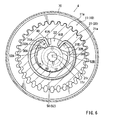
- Fig. 5 shows an internal structure of the reclining apparatus 4.
- the outer gear 21 is formed to have a diameter smaller than that of the inner gear 11 and to have a number of teeth smaller than that of the inner gear 11.
- the number of teeth of the outer tooth 21a of the outer gear 21 is 33 and the number of teeth of the inner tooth 11a of the inner gear 11 is 34. Therefore, by circulating the outer tooth member 20 to perform a revolving movement along and relative to a tooth face on an inner peripheral side in a state where the outer gear 21 is in meshing with the inner gear 11, a positional relationship relative to the inner tooth member 10 in the rotational direction is shifted at each revolution due to the different in number of teeth mentioned above.
- the positional relationship in the rotational direction is shifted in the same direction as the direction of rotation of the outer gear 21. That is, in Fig. 5 , for example, when the outer gear 21 is moved relative to (relatively revolved) and along the inner peripheral face of the inner gear in the clockwise direction while the outer gear 21 circulates in the counterclockwise direction along the inner peripheral face of the inner gear 11, the outer tooth member 20 is moved to rotate in the counterclockwise direction relative to and along the inner tooth member 10. Further, actually, the outer tooth member 20 is attached to the cushion frame 3f, and the inner tooth member 10 is attached to the back frame 2f, and therefore, the inner tooth member 10 acts to rotate in the clockwise direction relative to the outer tooth member 20. Further, tooth shapes of the inner gear 11 and the outer gear 21 will be explained later in detail.
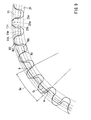
- the eccentric members 30A, 30B are formed as frame-like members bent along circular arcs and having configurations symmetrical with each other in a left and right direction.
- the eccentric members 30A, 30B are disposed within a gap formed between the inner peripheral face of the through hole 22 formed in the outer tooth member 20 and the outer peripheral face of the cylinder portion 12 formed in the inner tooth member 10. Therefore, portions of the gap are filled by the arrangement of the eccentric members 30A, 30B.
- the eccentric members 30A, 30B are arranged to be opposed to each other at positions on left and right sides to surround the outer peripheral face of the cylinder portion 12.
- each of the eccentric members 30A, 30B is formed to have a tapered shape in which the thickness decreases in a radial direction from a portion on an upper side to a portion on a lower side in the paper sheet face of the figure. Further, portions proximal to upper ends of the eccentric members 30A, 30B are formed with projected portions 31 A, 31 B protruding in the axial direction on the side opposed to the side of facing to the inner tooth member 10 in the drawings. As shown in Fig.
- faces of the projected portions 31 A, 31 B on the lower side in the paper sheet face are configured as contact faces 32A, 32B that are adapted to be contacted with and pressed by pushing face portions 52A, 52B of the pushing member 50 mentioned later.
- the contact faces 32A, 32B are formed to be inclined so as to be oriented radially inwardly with respect o the direction of rotation of the pushing member 50.
- the spring member 40 is formed to be bent in an open ring shape and to have latching portions 41 A, 41 B that are formed at opposite ends and latched with upper end portions of the respective eccentric members 30A, 30B.
- the spring member 40 urges the upper end portions of the respective eccentric members 30A, 30B in directions of separating the upper end portions from each other. Therefore, the eccentric members 30A, 30B are urged in directions of movement of the lower end portions toward each other under the guide of the gap shape between the outer peripheral face of the cylinder portion 12 and the inner peripheral face of the through hole 22.
- the outer tooth member 20 receives pressing forces by the wedging two eccentric members 30A, 30B from the inner peripheral face of the through hole 22 and is maintained in the state where the outer gear 21 is pressed against the inner peripheral face (inner tooth face) of the inner gear 11, so that its revolving movement is stopped.
- the eccentric members 30A, 30B applies wedging forces between the outer peripheral face on an upper side (two shoulder sides) as viewed in the drawings of the cylinder portion 12 and the inner peripheral face of the through hole 22 as they wedge into the gap shapes.
- the outer gear 21 is brought to the state where it is pushed upwardly as viewed in the drawings relative to the cylinder portion 12 (inner gear 11), and the outer tooth 21 a is maintained at a state where the inner tooth 11a is meshed with the inner tooth 11a without rattling (backlash).
- the pushing member 50 is integrally formed with a fitting portion 51 in a circular cylinder shape, into which the shaft pin 60 can be inserted, and a fin portion 52 extending radially outward in a manner like a fin at one end in an axial direction of the fitting portion 51.
- the fitting portion 51 of the former is formed with a serration-like groove face at an inner peripheral face of the cylinder shape and is integrally fitted with the shaft pin 60 in the rotational direction by inserting the shaft pin 60 into the cylinder.
- the fitting portion 51 is inserted into the inserting hole 12a of the cylinder portion 12 formed at the inner tooth member 10 so as to be assembled therewith in a state of being loosely fitted thereto. Therefore, the pushing member 50 is assembled in a state where it is rotatably supported by the cylinder portion 12. End face portions on the side of two shoulders of the fin shape as viewed in the drawings of the blade portion 52 of the latter are formed as pushing face portions 52A, 52B for pushing and moving the projected portions 31A, 31B of the respective eccentric members 30A, 30B. As shown in Fig.
- the pushing face portions 52A, 52B are formed to be inclined in such a manner that they are oriented toward radially outer sides relative to the direction of rotation of the pushing member 50 to cause contact in face with the contact faces 32A, 32B of the respective projected portions 31A, 31B.
- the fin portion 52 is arranged to take a position where it is pinched at a position between the projected portions 31 A, 31 B formed at the respective eccentric members 30A, 30B. Therefore, when, for example, the shaft pin 60 is operated to rotate in the clockwise direction in the paper sheet face from the illustrated state, also the pushing member 50 is operated to rotate in the clockwise direction integrally therewith. Therefore, as shown in Fig. 6 , the pushing face portion 52A on the left shoulder side of the paper sheet face of the blade portion 52 pushes to move the projected portion 31A of the eccentric member 30A arranged on the left side and pushes to move the eccentric member 30A in a direction opposite to the urged wedging direction.
- the pushing face portion 52A pushes to move the eccentric member 30A in the clockwise direction as viewed in the drawings while pushing the eccentric member 30A toward the radially outer side by the contact face structures inclined to each other. Therefore, the wedging state of the eccentric member 30A on the left side is released.
- the eccentric member 30A rotates in the clockwise direction as viewed in the drawings
- the eccentric member 30B on the right side is operated to rotate in the clockwise direction as viewed in the drawings as it receives the urging force of the spring member 40. Therefore, the inner peripheral face of the through hole 22 formed at the outer gear 21 is pushed by the eccentric clockwise rotation of the two eccentric members 30A, 30B so as to be pressed successively in the clockwise direction as viewed in the drawings while being pushed radially outward.
- the outer tooth member 20 rotates to revolve in the clockwise direction along the inner peripheral face of the inner gear 11 while the outer tooth member 20 per se is rotates in the counterclockwise direction as viewed in the drawings in the state where the outer gear 21 is meshed with the inner gear 11.
- the eccentric members 30A, 30B enter the narrowed gaps between the outer peripheral face of the cylinder portion 12 and the inner peripheral face of the through hole 22 so as to be again brought to the wedging state therebetween and are maintained in this state.
- the outer peripheral ring 70 is formed in a shape of a stepped circular cylinder by a half blanking process of a member in a shape of a thin hollow circular disk in a plate thickness direction (axial direction).
- a face of a portion of the outer peripheral ring 70 on an inner peripheral edge side is formed as an inner tooth side holding face 71 that is adapted to contact with a face of a portion on an outer peripheral edge side of the outer side circular disk face of the inner tooth member 10. Further, as shown in Fig.
- a face of a portion on an outer peripheral edge side of the outer ring 70 is formed as an outer tooth side holding face 72 that is crimped in such a manner that it contacts with a face of a portion on an outer peripheral edge side of an outer side circular disk face of the outer tooth member 20.
- the outer peripheral ring 70 is configured to be able to maintain always a state where at least a portion of the outer side circular disk face of the inner tooth member 10 contacts by the outer tooth side holding face 72 when the inner tooth member 10 is moved to revolve relative to the outer tooth member 20. Therefore, the inner tooth member 10 and the outer tooth member 20 are maintained in a state where they are pinched by the outer peripheral ring 70 so as not to move for separating in the plate thickness direction
- Fig. 7 shows pitch circles 11p, 21p of the inner gear 11 and the outer gear 21 and their contact point locus line Tr.
- the tooth shapes of the inner gear 11 and the outer gear 21 are determined such that a meshing line between them, that is, the contact point locus line Tr passing a point where the inner teeth 11a and the outer teeth 21a contact with each other is drawn to have a spiral shape.
- the tooth shapes of the inner gear 11 and the outer gear 21 are determined respectively by the following procedure.
- Two circles indicated by solid lines in Fig. 7 are pitch circles 11p, 21p of the inner gear 11 and the outer gear 21, respectively.
- Diameters of the pitch circles 11p, 21p are respectively given by products of tooth numbers of the respective gears (tooth number of inner gear 11: 34, tooth number of outer gear 21: 33) by a module (2.6).
- the diameter of the pitch circle 11p is given as 88.4mm
- the diameter of the pitch circle 21p is given as 85.8mm.
- the pitch circles 11p, 21p contact with each other at an intersection P in the drawing, and a distance between centers 11r, 21r of them is given as 1.3mm from the above-described geometrical relationship.
- the contact point locus line Tr representing the meshing line of the inner gear 11 and the outer gear 21 is arbitrarily given by an Archimedean spiral.
- a region (meshing region Ge) where the contact point locus line Tr is drawn is determined as a region between intersections a, b of an effective addendum circle 11h of the inner gear 11 and an effective addendum circle 21h of the outer gear 21 that will be described later.
- a point O is arbitrarily determined at a position on the contact point locus line Tr, and points B1, B2, B3... are further arbitrarily determined at positions successively remote from the point O little by little.
- the contact point locus line Tr is indicated to be longer than its actual length.
- a normal line Ve1 to a line segment P-O passing through point O is drawn.
- point B1 and point P are rotated in the clockwise direction in the paper sheet face about center 11r without changing a relative positional relationship between center 11r of the inner gear 11, point B1 and point P.
- an intersecting point between point B1 and normal line Ve1 is determined as A1, and a position of point P after the movement by the rotation is determined as point P1.
- a normal line Ve2 to a line segment P1-A1 passing through point A1 is drawn.
- point B2 and point P are rotated in the clockwise direction in the paper sheet face about center 11r without changing a relative positional relationship between center 11r of the inner gear 11, point B2 and point P.
- an intersecting point between point B2 and normal line Ve2 is determined as A2 and a position of point P after the movement by the rotation is determined as point P2.
- the tooth shape of the outer gear 21 can be given by successively moving points determined on the contact point locus line Tr about the center 21r of the outer gear 21.
- the method of determining the tooth shape from the geometrical relationship between the two pitch circles 11p, 21p and the contact point locus line Tr is a publicly-known method and is described in a document, such as a publication ("Illustrated Mechanism", edited by FUKUNAGA setuo et al, first edition, Rikogaku-sha, April 10, 1972, Figs. 10 .2) or the like.
- the tooth shapes of the inner gear 11 and the outer gear 21 are given as shown in Fig. 9 by using the above-described method.
- addendums and deddendums of the inner gear 11 and the outer gear 21 are respectively provided with R shape portions (rounded shape portions) R1 through R4 that are necessary when press-molding.
- R shape portion R1 constituting the addendum of the inner gear 11 is formed to extend from an addendum circle 11m to the effective addendum circle 11h set to the inner gear 11.
- an R shape portion R3 constituting an addendum of the outer gear 21 is formed to extend from an addendum circle 21m to an effective addendum circle 21h set to the outer gear 21.
- an R shape portion R2 constituting a deddendum of the inner gear 11 is formed to extend from a deddendum circle 11n to an effective deddendum circle, not illustrated, set to the inner gear 11.
- an R shape portion R4 constituting a deddendum of the outer gear 21 is formed to extend from a deddendum circle 21n to an effective deddendum circle, not illustrated, set to the outer gear 21. Further, in the reclining apparatus 4 on a large shape side, sizes of its portions are determined such that a diameter of the deddendum circle 11n of the inner gear 11 becomes to be 61.6mm.
- the contact point locus line Tr constituting the Archimedean spiral is adopted, and therefore, a meshing line having a long line length is given in the meshing region Ge between the effective addendum circle 11h and the effective addendum circle 21h. Therefore, a meshing rate of the two gears in the reclining apparatus 4 on the large shape side is set between 2 and 3.
- the meshing rate is a numerical value given by dividing a line length of the contact point locus line Tr by a normal line pitch.
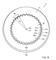
- Fig. 10 shows entire tooth shapes of the inner gear 11 and the outer gear 21 of the reclining apparatus 4 formed by the above-described method. Therefore, the operation of adjusting the backrest angle (pivoting operation) of the seat back 2 can be carried out on the left and on the right with an excellent balance in synchronism with each other by cooperative operations of the two reclining apparatus 4,4.
- a method of using the embodiment is omitted because this method is explained by the operating structures the reclining apparatus 4, 4 described above.
- the tooth shapes are formed such that the meshing line for meshing of the gear trains of the inner gear 11 and the outer gear 21 arranged as the reclining apparatus 4 of the vehicular seat is defined as a spiral mesh line, so that the meshing rate of the gear train can be improved. Therefore, the operation of adjusting the backrest angle of the seat back 2 can excellently be carried out. Further, by setting the mesh line of the gear train to the Archimedean spiral having a constant circumferential interval, the shapes of the inner gear 11 and the outer gear 21 can highly accurately be finished by a numerical control.
- the operation for maintaining or adjusting the backrest angle of the seat back 2 can further excellently be carried out.
- the tooth number of the outer gear may be larger than that of the inner gear.
- the outer tooth member rotates relative to the inner tooth member in a direction opposite to the direction shown in the embodiment in accordance with the relative revolution of the outer gear.
- the spirals are not limited to spirals drawn by bent curves but may be spirals drawn by bending a linear line little by little.
- the spring member is illustrated as the urge member for urging the pair of eccentric members in directions toward each other, other urge member, such as a rubber member or the like, is also applicable.
Abstract
Description
- The present invention relates to gears and a coupling apparatus using the gears. More specifically, the present invention relates to gears constituting a gear train provided in a state of meshing with each other for enabling transmission of a power.
- In a background art, in a vehicular seat, there is known a constitution of arranging a reclining apparatus operable to adjust a backrest angle of a seat back. Here,
JP-A-2005-83535
Further, according to the disclosure, a tooth shape of the above-described inner gear or outer gear is formed to have a shape of a cycloid curve or a trochoid curve. For this reason, a meshing line of the two gears is set to a shape of a circular arc, and therefore, in comparison with a gear train of a publicly-known tooth shape having an involute curve resulting a linear meshing line, a meshing strength can be increased by the increase in the meshing rate. - However, according to the background art described in the above patent document, although the meshing line of the gear train can be set to the shape of the circular arc, the meshing rate can be adjusted only within a limited narrow range.
- The invention has been created in order to solve the above-described problem and a problem to be solved by the invention resides in increasing a meshing rate of a gear train.
-
US-A-5913744 discloses a gear train comprising an inner gear within an outer gear, and having a few teeth in engagement at any time. The gears have a conical mesh line.
US-2002/170373A discloses a gear tooth having a variable face width with respect to tooth height, in order to give an altered tooth stiffness. The load distribution on the tooth is changed to reduce gear noise and increase power density.
US-A-3982445 discloses a gear tooth profile of changing radius of curvature, so as to avoid overloading of any single tooth profile. Greater machining errors can be accommodated, surface stress is reduced, and torque capacity is increased. - In order to solve the problem, gears and a coupling apparatus using the gears of the invention adopts the following means. According to the invention there is provided a coupling apparatus comprising a reclining apparatus coupling a seat back and a seat cushion of a vehicle seat; the reclining apparatus including:
- an inner tooth member including an inner gear coupled to one of the seat back and the seat cushion; and
- an outer tooth member including an outer gear assembled in meshing with the inner gear of the inner tooth member and coupled to other of the seat back and the seat cushion;
- the outer gear being smaller than the inner gear at a diameter thereof and formed to have a tooth number different from a tooth number of the inner gear; and
- a backrest angle of the seat back being varied by a relative circulating movement of the outer gear on an inner tooth face of the inner gear in a state where the outer gear meshes with the inner gear, characterized in that the meshing line given by the gear train of the outer gear and the inner gear is configured as an Archimedean spiral.
- According to the invention, the reclining apparatus is operated to adjust the backrest angle of the seat back by the relative circulating movement of the outer gear on an inner tooth face of the inner gear. Because the meshing line given by the gear train of the outer gear and the inner gear is configured as a spiral mesh line, a length of the meshing line existing inside of a predetermined region in a circumferential direction is set to be longer. The meshing line given by the meshing of the gear train is drawn by the Archimedean spiral having a constant circumferential interval.
- In one embodiment, the inner gear is formed to project in a circular cylinder shape from the inner gear member by a half blanking process. Also, the outer gear is formed to project in a circular cylinder shape from the outer gear member by a half blanking process. The inner tooth member is formed with a cylinder portion in a circular cylinder shape projecting from a center portion of the inner gear. The outer tooth member is formed with a through hole in a circular shape at a center portion of the outer gear for receiving therein and surrounding the cylinder portion formed on the inner tooth member. The cylinder portion and the through hole have a positional relationship in which their center portions are offset from each other. Further, within a gap between the cylinder portion of the inner tooth member and the through hole of the outer tooth member surrounding the cylinder portion, a pair of eccentric members each having a shape of filling a portion of a shape of the gap are disposed. The pair of eccentric members normally wedge into narrowed portions of the gap shape in an inserted manner by being urged and are maintained in a state where the outer gear is pressed against the inner peripheral tooth face of the inner gear. As either one of the eccentric members is operated to be pushed in a circumferential direction by a rotational operation of a shaft pin inserted into a cylinder of the cylinder portion, the either one of the eccentric members is released from the wedging state and presses against an inner peripheral face of the through hole of the outer tooth member to cause circulating movement of the outer gear.
According to this aspect, because the pair of eccentric members wedge into narrowed portions of the gap shape in an inserted manner by being urged and are maintained in the state where the outer gear is pressed against the inner peripheral tooth face of the inner gear, the two gears are maintained in the state where they are prevented from rotation relative to each other without a backlash. As either one of the eccentric members is operated to be pushed in the circumferential direction by the rotational operation of the shaft pin inserted into the cylinder of the cylinder portion, the either one of the eccentric members is released from the wedging state and presses against the inner peripheral face of the through hole of the outer tooth member to cause circulating movement of the outer gear. - The invention can achieve the following effect by adopting the above-described means.
By defining the meshing line of the gear train as the Archimedean spiral having the constant circumferential interval, the tooth shapes can highly accurately be finished by a numerical control.
Further, by the construction in which the pair of eccentric members press the outer gear against the inner peripheral tooth face of the inner gear to maintain the state where their positional condition is maintained without a backlash or in which the outer gear is pushed to cause revolution, the operation for maintaining or adjusting the backrest angle of the seat back can further excellently be carried out. -
- [
Fig. 1] Fig. 1 is an exploded perspective view of a reclining apparatus of Embodiment 1. - [
Fig. 2] Fig. 2 is a perspective view showing a schematic constitution of a vehicular seat. - [
Fig. 3] Fig. 3 is an exploded perspective view showing a structure of assembling a reclining apparatus with a vehicular seat. - [
Fig. 4] Fig. 4 is a sectional view taken along a line IV-IV inFig. 3 . - [
Fig. 5] Fig. 5 is a sectional view taken along a line V-V inFig. 4 . - [
Fig. 6] Fig. 6 is a constitutive view showing the state where the wedging state of an eccentric member is released from the state inFig. 5 . - [
Fig. 7] Fig. 7 is a constitutive view showing a pitch circle and a contact point locus line of each gear of a reclining apparatus. - [
Fig. 8] Fig. 8 is a constitutive view showing a procedure of determining a tooth shape of an inner gear of the reclining apparatus. - [
Fig. 9] Fig. 9 is a constitutive view showing tooth shapes of an inner gear and an outer gear of the reclining apparatus in an enlarged scale. - [
Fig. 10] Fig. 10 is a constitutive view showing the entire tooth shapes of an inner gear and an outer gear of the reclining apparatus. -
- 1... vehicular seat
- 2... seat back
- 2f... back frame
- 2a... dowel hole
- 2b... D dowel hole
- 2c... inserting hole
- 3... seat cushion
- 3f... cushion frame
- 3a... dowel hole
- 3b... D dowel hole
- 3c... inserting hole
- 4... reclining apparatus
- 10... inner tooth member
- 11... inner gear
- 11a... inner tooth
- 11r... center
- 11p... pitch circle
- 11h... effective addendum circle
- 11m... addendum circle
- 11n... deddendum circle
- 12... cylinder portion
- 12a... inserting hole
- 13a... dowel
- 13b... D dowel
- 20... outer tooth member
- 21... outer gear
- 21a... outer tooth
- 2 1 r... center
- 21 p... pitch circle
- 21h... effective addendum circle
- 21m... addendum circle
- 21n... deddendum circle
- 22... through hole
- 23a... dowel
- 23b... D dowel
- 30A, 30B... eccentric members
- 31A, 31B... projected portions
- 32A, 32B... contact faces
- 40... spring member
- 41 A, 41B... latching portions
- 50... pushing member
- 51... fitting portion
- 52... fin
- 52A, 52B... pushing face portion
- 60... shaft pin
- 70... outer peripheral ring
- 71... inner tooth side holding face
- 72... outer tooth side holding face
- Tr... contact point locus line
- P, O... points
- B1 through B3... points
- A1 through A3... points
- P1 through P3... points
- Ve1 through Ve3... normal lines
- Ge... mesh region
- R1 through R4... R shape portions
- a, b... intersections
- Embodiments of the best mode for carrying out the invention will be explained in reference to the drawings as follows.
- At first, the construction of gears of Embodiment 1 and a coupling apparatus using the gears will be explained in reference to
Fig. 1 through Fig. 10 . Here,Fig. 2 schematically shows in a perspective view the construction of a vehicular seat 1 includingreclining apparatus - The vehicular seat 1 is constructed to include a seat back 2 constituting a back rest and a
seat cushion 3 constituting a seating portion and to connect these elements by a pair of thereclining apparatus seat cushion 3 in accordance with a cooperative operation of the respectivereclining apparatus reclining apparatus
The detailed constitution of thereclining apparatus reclining apparatus reclining apparatus 4 shown on the right side of the drawings as a representative of them. - Here,
Fig. 1 shows an exploded perspective view of thereclining apparatus 4. Thereclining apparatus 4 is configured to operate as ashaft pin 60 inserted into a center position thereof is operated to rotate in accordance with driving for rotation of an electric motor, not illustrated. The electric motor is configured to be operated for switching to ON/OFF and normal rotation/reverse rotation by the switching operating of switch a switch, not illustrated, arranged, for example, at a position of a side portion or the like of the vehicular seat 1.
Thereclining apparatus 4 is under the state of maintaining the backrest angle of the seat back 2 normally before theshaft pin 60 is operated to rotate. Further, thereclining apparatus 4 is configured to perform the operation for adjusting the backrest angle of the seat back 2 by the rotational movement of theshaft pin 60 as the shaft pin is operated to be driven.
Specifically, thereclining apparatus 4 is constituted by an assembly of aninner tooth member 10, anouter tooth member 20, a pair ofeccentric members spring member 40, a pushingmember 50, theshaft pin 60, and an outerperipheral ring 70. These members are formed of metal members.
The detailed constructions of these members will be explained in detail successively as follows. - First, the
inner tooth member 10 will be explained. - The
inner tooth member 10 is formed in a shape of a circular disk and is formed to have an outer peripheral edge of the circular disk shape projecting in a shape of a circular cylinder toward theouter tooth member 20 by a half blanking process in an axial direction. Further,inner teeth 11a are formed on an inner peripheral face of the projected portion having a circular cylinder shape. Therefore, the projected portion having the circular cylinder shape is formed as aninner gear 11. - Further, an inserting
hole 12a capable of inserting theshaft pin 60 in the axial direction is formed in a center portion of theinner tooth member 10. The insertinghole 12a is formed to penetrate in a plate thickness direction of theinner tooth member 10 and its center is coaxial with acenter 11r of theinner gear 11. - Further, the
inner tooth member 10 is formed with acylinder portion 12 in a shape of projecting in a circular cylinder shape toward theouter tooth member 20 by a half blanking process of a peripheral edge portion of the insertinghole 12a in the axial direction. - Here,
Fig. 3 shows a structure for attaching thereclining apparatus 4 to the seat back 2 or theseat cushion 3. As shown in the drawing, an outer side circular disk face of theinner tooth member 10 is formed withdowels 13a and aD dowel 13b at positions spaced from the insertinghole 12a in a radial direction and aligned in a circumferential direction.
Thedowels 13a and theD dowel 13b are formed to project in the axial direction from the outer side circular disk face by a half blanking process of theinner tooth member 10 in the axial direction. Further, thedowels 13a and theD dowel 13b are configured to be fitted intocorresponding dowel holes 2a and a correspondingD dowel hole 2b formed in aback frame 2f constituting a skeleton of the seat back 2. - Further, the
back frame 2f is also formed with an inserting hole 2c, into which the shaft pin 60 (refer toFig. 1 ) can be inserted, on the same axis line as that of the insertinghole 12a formed in theinner tooth member 10. Here, theD dowel 13b is formed to have a shape of the circular cylinder, a part of which is notched to have a D-like cross section, and the shape is differentiated from that of thedowel 13a having the circular cylinder shape. Therefore, theinner tooth member 10 can be fitted to theback frame 2f so as to be integrally joined thereto, while it is always oriented in a predetermined direction.
The joining between theinner tooth member 10 and theback frame 2f is carried out by arc-welding portions of fitting thedowels 13a and theD dowel 13b in a state where the outer side circular disk face of theinner tooth member 10 and a plate face of theback frame 2f are in a face contact relationship with each other. Here, the state of joining between theinner tooth member 10 and theback frame 2f is shown in detail inFig. 4 . - Next, referring back to
Fig. 1 , theouter tooth member 20 will be explained. - The
outer tooth member 20 is formed in a circular disk shape and is formed to have a central portion other than an outer peripheral edge of the circular disk shape projecting in a circular cylinder shape toward theinner tooth member 10 by a half blanking process in the axial direction. Further, an outer peripheral face of the projected portion in the circular disk shape is formed withouter teeth 21a. Therefore, the portion projected in the circular cylinder shape is formed as anouter gear 21. - Further, a center portion of the
outer tooth member 20 is formed with a throughhole 22 penetrating in a plate thickness direction. An inner diameter of the throughhole 22 is formed to be larger than an outer diameter of thecylinder portion 12 formed on theinner tooth member 10. The throughhole 22 is arranged in a state of surrounding an outer peripheral edge of thecylinder portion 12 at inside thereof in a state where theouter tooth member 20 and theinner tooth member 10 are assembled to be overlapped at their circular disk faces. The center of the throughhole 22 is coaxial with acenter 21r of theouter gear 21 to have a relationship in arrangement therewith such that the throughhole 22 and thecylinder portion 12 are offset from each other. - An outer peripheral edge of the outer side circular disk face of the
outer tooth member 20 is formed withdowels 23a and aD dowel 23b projecting in the axial direction and aligned in a circumferential direction. Thedowels 23a and theD dowel 23b function in the same manner as thedowels 13a and theD dowel 13a explained in theinner tooth member 10. That is, as shown inFig. 3 , thedowels 23a and theD dowel 23b are constituted as fitting portions that are fitted intocorresponding dowel holes 3a and a correspondingD dowel hole 3b formed in acushion frame 3f constituting a skeleton of theseat cushion 3.
Further, thecushion frame 3f is also formed with an insertinghole 3c, into which the shaft pin 60 (refer toFig. 1 ) can be inserted on the same axis line as that of the insertinghole 12a formed in theinner tooth member 10. Therefore, theouter tooth member 20 is integrally joined with thecushion frame 3f in a state where it is fitted always in a predetermined direction. The state of joining between theouter tooth member 20 and thecushion frame 3f is shown in detail inFig. 4 . - Here,
Fig. 5 shows an internal structure of thereclining apparatus 4. As shown in the drawing, theouter gear 21 is formed to have a diameter smaller than that of theinner gear 11 and to have a number of teeth smaller than that of theinner gear 11. Specifically, the number of teeth of theouter tooth 21a of theouter gear 21 is 33 and the number of teeth of theinner tooth 11a of theinner gear 11 is 34.
Therefore, by circulating theouter tooth member 20 to perform a revolving movement along and relative to a tooth face on an inner peripheral side in a state where theouter gear 21 is in meshing with theinner gear 11, a positional relationship relative to theinner tooth member 10 in the rotational direction is shifted at each revolution due to the different in number of teeth mentioned above. - Specifically, the positional relationship in the rotational direction is shifted in the same direction as the direction of rotation of the
outer gear 21. That is, inFig. 5 , for example, when theouter gear 21 is moved relative to (relatively revolved) and along the inner peripheral face of the inner gear in the clockwise direction while theouter gear 21 circulates in the counterclockwise direction along the inner peripheral face of theinner gear 11, theouter tooth member 20 is moved to rotate in the counterclockwise direction relative to and along theinner tooth member 10. Further, actually, theouter tooth member 20 is attached to thecushion frame 3f, and theinner tooth member 10 is attached to theback frame 2f, and therefore, theinner tooth member 10 acts to rotate in the clockwise direction relative to theouter tooth member 20.
Further, tooth shapes of theinner gear 11 and theouter gear 21 will be explained later in detail. - Next, referring back to
Fig. 1 , theeccentric members eccentric members eccentric members hole 22 formed in theouter tooth member 20 and the outer peripheral face of thecylinder portion 12 formed in theinner tooth member 10. Therefore, portions of the gap are filled by the arrangement of theeccentric members Fig. 5 , theeccentric members cylinder portion 12. - Here, as shown in
Fig. 1 , each of theeccentric members eccentric members portions inner tooth member 10 in the drawings. As shown inFig. 5 , faces of the projectedportions face portions member 50 mentioned later. The contact faces 32A, 32B are formed to be inclined so as to be oriented radially inwardly with respect o the direction of rotation of the pushingmember 50. - Next, referring back to
Fig. 1 , thespring member 40 will be explained. That is, thespring member 40 is formed to be bent in an open ring shape and to have latchingportions eccentric members
As is understood by referring toFig. 5 , thespring member 40 urges the upper end portions of the respectiveeccentric members eccentric members cylinder portion 12 and the inner peripheral face of the throughhole 22. By urging theeccentric members cylinder portion 12 and the inner peripheral face of the throughhole 22. - Therefore, the
outer tooth member 20 receives pressing forces by the wedging twoeccentric members hole 22 and is maintained in the state where theouter gear 21 is pressed against the inner peripheral face (inner tooth face) of theinner gear 11, so that its revolving movement is stopped.
In detail, theeccentric members cylinder portion 12 and the inner peripheral face of the throughhole 22 as they wedge into the gap shapes. Therefore, theouter gear 21 is brought to the state where it is pushed upwardly as viewed in the drawings relative to the cylinder portion 12 (inner gear 11), and theouter tooth 21 a is maintained at a state where theinner tooth 11a is meshed with theinner tooth 11a without rattling (backlash). - Next, referring back to
Fig. 1 , the pushingmember 50 will be explained. That is, the pushingmember 50 is integrally formed with afitting portion 51 in a circular cylinder shape, into which theshaft pin 60 can be inserted, and afin portion 52 extending radially outward in a manner like a fin at one end in an axial direction of thefitting portion 51.
Thefitting portion 51 of the former is formed with a serration-like groove face at an inner peripheral face of the cylinder shape and is integrally fitted with theshaft pin 60 in the rotational direction by inserting theshaft pin 60 into the cylinder. Further, thefitting portion 51 is inserted into the insertinghole 12a of thecylinder portion 12 formed at theinner tooth member 10 so as to be assembled therewith in a state of being loosely fitted thereto. Therefore, the pushingmember 50 is assembled in a state where it is rotatably supported by thecylinder portion 12.
End face portions on the side of two shoulders of the fin shape as viewed in the drawings of theblade portion 52 of the latter are formed as pushingface portions portions eccentric members Fig. 5 , the pushingface portions member 50 to cause contact in face with the contact faces 32A, 32B of the respective projectedportions - Further, as shown in
Fig. 5 , thefin portion 52 is arranged to take a position where it is pinched at a position between the projectedportions eccentric members shaft pin 60 is operated to rotate in the clockwise direction in the paper sheet face from the illustrated state, also the pushingmember 50 is operated to rotate in the clockwise direction integrally therewith.
Therefore, as shown inFig. 6 , the pushingface portion 52A on the left shoulder side of the paper sheet face of theblade portion 52 pushes to move the projectedportion 31A of theeccentric member 30A arranged on the left side and pushes to move theeccentric member 30A in a direction opposite to the urged wedging direction. In detail, the pushingface portion 52A pushes to move theeccentric member 30A in the clockwise direction as viewed in the drawings while pushing theeccentric member 30A toward the radially outer side by the contact face structures inclined to each other. Therefore, the wedging state of theeccentric member 30A on the left side is released. - Further, because the
eccentric member 30A rotates in the clockwise direction as viewed in the drawings, theeccentric member 30B on the right side is operated to rotate in the clockwise direction as viewed in the drawings as it receives the urging force of thespring member 40. Therefore, the inner peripheral face of the throughhole 22 formed at theouter gear 21 is pushed by the eccentric clockwise rotation of the twoeccentric members outer tooth member 20 rotates to revolve in the clockwise direction along the inner peripheral face of theinner gear 11 while theouter tooth member 20 per se is rotates in the counterclockwise direction as viewed in the drawings in the state where theouter gear 21 is meshed with theinner gear 11.
Further, due to the stop of the rotational operation of theshaft pin 60, by the urge force of thespring member 40, theeccentric members cylinder portion 12 and the inner peripheral face of the throughhole 22 so as to be again brought to the wedging state therebetween and are maintained in this state. - Next, referring back to
Fig. 1 , the outerperipheral ring 70 will be explained. The outerperipheral ring 70 is formed in a shape of a stepped circular cylinder by a half blanking process of a member in a shape of a thin hollow circular disk in a plate thickness direction (axial direction). A face of a portion of the outerperipheral ring 70 on an inner peripheral edge side is formed as an inner toothside holding face 71 that is adapted to contact with a face of a portion on an outer peripheral edge side of the outer side circular disk face of theinner tooth member 10. Further, as shown inFig. 4 , a face of a portion on an outer peripheral edge side of theouter ring 70 is formed as an outer toothside holding face 72 that is crimped in such a manner that it contacts with a face of a portion on an outer peripheral edge side of an outer side circular disk face of theouter tooth member 20.
As shown inFig. 4 , the outerperipheral ring 70 is configured to be able to maintain always a state where at least a portion of the outer side circular disk face of theinner tooth member 10 contacts by the outer toothside holding face 72 when theinner tooth member 10 is moved to revolve relative to theouter tooth member 20. Therefore, theinner tooth member 10 and theouter tooth member 20 are maintained in a state where they are pinched by the outerperipheral ring 70 so as not to move for separating in the plate thickness direction - Next, tooth shapes of the
inner gear 11 and theouter gear 21 of the above-describedreclining apparatus 4 will be explained in reference toFig. 7 through Fig. 10 . - Here,
Fig. 7 showspitch circles inner gear 11 and theouter gear 21 and their contact point locus line Tr.. As shown in the drawings, the tooth shapes of theinner gear 11 and theouter gear 21 are determined such that a meshing line between them, that is, the contact point locus line Tr passing a point where theinner teeth 11a and theouter teeth 21a contact with each other is drawn to have a spiral shape. Specifically, the tooth shapes of theinner gear 11 and theouter gear 21 are determined respectively by the following procedure. - First, a method of determining the tooth shape of the
inner gear 11 will be explained. Two circles indicated by solid lines inFig. 7 arepitch circles inner gear 11 and theouter gear 21, respectively. Diameters of thepitch circles pitch circle 11p is given as 88.4mm, and the diameter of thepitch circle 21p is given as 85.8mm.
Further, thepitch circles centers
Further, the contact point locus line Tr representing the meshing line of theinner gear 11 and theouter gear 21 is arbitrarily given by an Archimedean spiral. A region (meshing region Ge) where the contact point locus line Tr is drawn is determined as a region between intersections a, b of aneffective addendum circle 11h of theinner gear 11 and aneffective addendum circle 21h of theouter gear 21 that will be described later. - At first, as shown by
Fig. 8 , in order to determine the tooth shape of theinner gear 11, a point O is arbitrarily determined at a position on the contact point locus line Tr, and points B1, B2, B3... are further arbitrarily determined at positions successively remote from the point O little by little. Here, inFig. 8 , for better understanding of the explanation, the contact point locus line Tr is indicated to be longer than its actual length.
Next, a normal line Ve1 to a line segment P-O passing through point O is drawn. Further, point B1 and point P are rotated in the clockwise direction in the paper sheet face aboutcenter 11r without changing a relative positional relationship betweencenter 11r of theinner gear 11, point B1 and point P. Then, by this rotation, an intersecting point between point B1 and normal line Ve1 is determined as A1, and a position of point P after the movement by the rotation is determined as point P1.
Next, a normal line Ve2 to a line segment P1-A1 passing through point A1 is drawn. Further, point B2 and point P are rotated in the clockwise direction in the paper sheet face aboutcenter 11r without changing a relative positional relationship betweencenter 11r of theinner gear 11, point B2 and point P. Further, by this rotation, an intersecting point between point B2 and normal line Ve2 is determined as A2 and a position of point P after the movement by the rotation is determined as point P2. - Similarly, a normal line Ve3 to a line segment P2-A2 passing through point A2 is drawn. Further, point B3 and point P are rotated in the clockwise direction in the paper sheet face about
center 11r without changing a relative positional relationship betweencenter 11r of theinner gear 11, point B3 and point P. Further, by this rotation, an intersecting point between point B3 and normal line Ve3 by the rotation is determined as A3, and a position of point P after the movement by the rotation is determined as point P3.
When points O, A1, A2, A3... successively obtained in the same manner are smoothly connected, this gives a portion of the tooth shape of theinner gear 11. Similarly, also the tooth shape of theouter gear 21 can be given by successively moving points determined on the contact point locus line Tr about thecenter 21r of theouter gear 21.
The method of determining the tooth shape from the geometrical relationship between the twopitch circles Figs. 10 .2) or the like. - Therefore, the tooth shapes of the
inner gear 11 and theouter gear 21 are given as shown inFig. 9 by using the above-described method.
Here, addendums and deddendums of theinner gear 11 and theouter gear 21 are respectively provided with R shape portions (rounded shape portions) R1 through R4 that are necessary when press-molding. Among them, an R shape portion R1 constituting the addendum of theinner gear 11 is formed to extend from anaddendum circle 11m to theeffective addendum circle 11h set to theinner gear 11. Further, an R shape portion R3 constituting an addendum of theouter gear 21 is formed to extend from anaddendum circle 21m to aneffective addendum circle 21h set to theouter gear 21. Further, an R shape portion R2 constituting a deddendum of theinner gear 11 is formed to extend from adeddendum circle 11n to an effective deddendum circle, not illustrated, set to theinner gear 11. Further, an R shape portion R4 constituting a deddendum of theouter gear 21 is formed to extend from adeddendum circle 21n to an effective deddendum circle, not illustrated, set to theouter gear 21.
Further, in thereclining apparatus 4 on a large shape side, sizes of its portions are determined such that a diameter of thededdendum circle 11n of theinner gear 11 becomes to be 61.6mm. - The
inner gear 11 and theouter gear 21, the shapes of which are formed as described above, mesh with each other at a tooth face position on the contact point locus line Tr. According to the embodiment, the contact point locus line Tr constituting the Archimedean spiral is adopted, and therefore, a meshing line having a long line length is given in the meshing region Ge between theeffective addendum circle 11h and theeffective addendum circle 21h. Therefore, a meshing rate of the two gears in thereclining apparatus 4 on the large shape side is set between 2 and 3. Here, the meshing rate is a numerical value given by dividing a line length of the contact point locus line Tr by a normal line pitch. The higher the numerical value of the meshing rate, the higher the meshing strength of the two gears, and the higher the connection strength of thereclining apparatus 4.
Further,Fig. 10 shows entire tooth shapes of theinner gear 11 and theouter gear 21 of thereclining apparatus 4 formed by the above-described method.
Therefore, the operation of adjusting the backrest angle (pivoting operation) of the seat back 2 can be carried out on the left and on the right with an excellent balance in synchronism with each other by cooperative operations of the tworeclining apparatus
Here, a method of using the embodiment is omitted because this method is explained by the operating structures thereclining apparatus - In this way, according to the gears and the coupling apparatus using the gears of the embodiment, the tooth shapes are formed such that the meshing line for meshing of the gear trains of the
inner gear 11 and theouter gear 21 arranged as thereclining apparatus 4 of the vehicular seat is defined as a spiral mesh line, so that the meshing rate of the gear train can be improved. Therefore, the operation of adjusting the backrest angle of the seat back 2 can excellently be carried out.
Further, by setting the mesh line of the gear train to the Archimedean spiral having a constant circumferential interval, the shapes of theinner gear 11 and theouter gear 21 can highly accurately be finished by a numerical control.
Further, due to the construction of pressing theouter gear 21 against the inner peripheral tooth face of theinner gear 11 by the pair of theeccentric members outer gear 21 by pushing the same in the state without a backlash, the operation for maintaining or adjusting the backrest angle of the seat back 2 can further excellently be carried out. - Although the embodiment of the invention has been explained by using the one embodiment as described above, the invention can be carried out in various modes other than the embodiment.
The tooth number of the outer gear may be larger than that of the inner gear. In this case, the outer tooth member rotates relative to the inner tooth member in a direction opposite to the direction shown in the embodiment in accordance with the relative revolution of the outer gear.
The spirals are not limited to spirals drawn by bent curves but may be spirals drawn by bending a linear line little by little.
Further, although the spring member is illustrated as the urge member for urging the pair of eccentric members in directions toward each other, other urge member, such as a rubber member or the like, is also applicable.
Claims (2)
- A coupling apparatus comprising a reclining apparatus (4) coupling a seat back (2) and a seat cushion (3) of a vehicle seat (1);
the reclining apparatus (4) including:an inner tooth member (10) including an inner gear (11) coupled to one of the seat back and the seat cushion (2, 3); andan outer tooth member (20) including an outer gear (21) assembled in meshing with the inner gear (11) of the inner tooth member (10) and coupled to other of the seat back and the seat cushion (23);the outer gear (21) being smaller than the inner gear (11) at a diameter thereof and formed to have a tooth number different from a tooth number of the inner gear (11); anda backrest angle of the seat back (2) being varied by a relative circulating movement of the outer gear (21) on an inner tooth face of the inner gear (11) in a state where the outer gear (21) meshes with the inner gear (11), characterized in that the meshing line given by the gear train of the outer gear (21) and the inner gear (11) is configured as an Archimedean spiral (Tr). - The coupling apparatus according to Claim 1, characterized in that:the inner gear (11) is formed to project in a circular cylinder shape from the inner gear member by a half blanking process, and also the outer gear (21) is formed to project in a circular cylinder shape from the outer gear member by a half blanking process;the inner tooth member (10) is formed with a cylinder portion in a circular cylinder shape projecting from a center portion of the inner gear, the outer tooth member (20) is formed with a through hole in a circular shape at a center portion of the outer gear for receiving therein and surrounding the cylinder portion formed on the inner tooth member, and the cylinder portion and the through hole have a positional relationship in which their center portions are offset from each other; andwithin a gap between the cylinder portion of the inner tooth member (10) and the through hole of the outer tooth (20) member surrounding the cylinder portion, a pair of eccentric members (30A, 30B) each having a shape of filling a portion of a shape of the gap are disposed, the pair of eccentric members normally wedge into narrowed portions of the gap shape in an inserted manner by being urged and are maintained in a state where the outer gear (20) is pressed against the inner peripheral tooth face of the inner gear (11), and as either one of the eccentric members is operated to be pushed in a circumferential direction by a rotational operation of a shaft pin (60) inserted into a cylinder of the cylinder portion, the either one of the eccentric members is released from the wedging state and presses against an inner peripheral face of the through hole of the outer tooth member (20) to cause circulating movement of the outer gear (21).
Applications Claiming Priority (2)
| Application Number | Priority Date | Filing Date | Title |
|---|---|---|---|
| JP2006208331 | 2006-07-31 | ||
| PCT/JP2007/062012 WO2008015845A1 (en) | 2006-07-31 | 2007-06-14 | Gear and connection device using the gear |
Publications (3)
| Publication Number | Publication Date |
|---|---|
| EP2068040A1 EP2068040A1 (en) | 2009-06-10 |
| EP2068040A4 EP2068040A4 (en) | 2011-01-05 |
| EP2068040B1 true EP2068040B1 (en) | 2012-02-22 |
Family
ID=38997029
Family Applications (1)
| Application Number | Title | Priority Date | Filing Date |
|---|---|---|---|
| EP07745269A Expired - Fee Related EP2068040B1 (en) | 2006-07-31 | 2007-06-14 | Gear and connection device using the gear |
Country Status (5)
| Country | Link |
|---|---|
| US (1) | US8016356B2 (en) |
| EP (1) | EP2068040B1 (en) |
| JP (1) | JP4992901B2 (en) |
| CN (1) | CN101495779B (en) |
| WO (1) | WO2008015845A1 (en) |
Cited By (1)
| Publication number | Priority date | Publication date | Assignee | Title |
|---|---|---|---|---|
| KR20180060400A (en) * | 2016-11-29 | 2018-06-07 | 주식회사다스 | Car seat recliner and assembling method thereof |
Families Citing this family (16)
| Publication number | Priority date | Publication date | Assignee | Title |
|---|---|---|---|---|
| CN101677689B (en) * | 2007-05-08 | 2011-05-11 | 丰田纺织株式会社 | Connection device |
| US8460145B2 (en) * | 2007-06-11 | 2013-06-11 | Toyota Boshoku Kabushiki Kaisha | Rotation mechanism |
| JP5338165B2 (en) * | 2008-07-15 | 2013-11-13 | トヨタ紡織株式会社 | Gear and coupling device using the gear |
| JP5077115B2 (en) * | 2008-07-15 | 2012-11-21 | トヨタ紡織株式会社 | Gear and coupling device using the gear |
| DE102009040453A1 (en) * | 2009-08-28 | 2011-03-03 | Keiper Gmbh & Co. Kg | Fitting for a vehicle seat |
| DE102009039648B3 (en) * | 2009-08-28 | 2011-02-24 | Keiper Gmbh & Co. Kg | Fitting for a vehicle seat and vehicle seat |
| DE102009052512A1 (en) | 2009-11-11 | 2011-05-12 | Johnson Controls Gmbh | Tilt adjuster for vehicles |
| DE102011016656B3 (en) * | 2011-04-06 | 2012-08-30 | Keiper Gmbh & Co. Kg | Fitting for a vehicle seat and vehicle seat |
| JP5691793B2 (en) * | 2011-04-22 | 2015-04-01 | アイシン精機株式会社 | Seat reclining device |
| JP5809014B2 (en) * | 2011-05-13 | 2015-11-10 | シロキ工業株式会社 | Reduction gear mechanism |
| JP5872853B2 (en) * | 2011-11-08 | 2016-03-01 | シロキ工業株式会社 | Reclining device |
| JP5692819B2 (en) * | 2012-10-24 | 2015-04-01 | シロキ工業株式会社 | Reclining device |
| JP6232983B2 (en) | 2013-12-03 | 2017-11-22 | アイシン精機株式会社 | Deceleration device and seat drive device |
| JP6443118B2 (en) * | 2015-02-20 | 2018-12-26 | アイシン精機株式会社 | Internal gear and its rolling die |
| JP6568233B2 (en) * | 2015-04-24 | 2019-08-28 | エスアールアイ インターナショナルSRI International | Drive device with partial cycloidal tooth profile |
| CN115320459B (en) * | 2022-07-21 | 2024-03-22 | 恺博座椅机械部件有限公司 | High-strength continuous type seat eccentric angle adjuster |
Family Cites Families (16)
| Publication number | Priority date | Publication date | Assignee | Title |
|---|---|---|---|---|
| US32332A (en) * | 1861-05-14 | Improvement in electro-magnetic bathing apparatus | ||
| US3826152A (en) * | 1973-05-11 | 1974-07-30 | K Alexeev | Variable-ratio gear transmission |
| US3946621A (en) * | 1975-01-15 | 1976-03-30 | Rouverol William S | Internal gearing |
| US3982445A (en) * | 1975-09-02 | 1976-09-28 | Rouverol William S | High torque gearing |
| JPS56128247A (en) * | 1980-03-08 | 1981-10-07 | Fuji Kiko Co Ltd | Seat belt retractor |
| US4379976A (en) * | 1981-07-20 | 1983-04-12 | Rain Bird Sprinkler Mfg. Corp. | Planocentric gear drive |
| ATE176301T1 (en) * | 1993-12-17 | 1999-02-15 | J M Voith Gmbh & Co Beteiligun | SICKLELESS INTERNAL GEAR PUMP |
| SE502228C2 (en) | 1994-08-12 | 1995-09-18 | Gustav Rennerfelt | eccentric |
| CN2223213Y (en) * | 1994-10-09 | 1996-03-27 | 江苏省溧阳市汽车座椅调角器总厂 | Angle modulator |
| DE19750834C1 (en) | 1997-11-17 | 1998-10-29 | Gkn Viscodrive Gmbh | Locking differential for motor vehicle |
| US6248993B1 (en) * | 1998-08-05 | 2001-06-19 | Leopold Kostal Gmbh & Co. Kg | Steering angle sensor |
| DE19942477C2 (en) * | 1999-09-06 | 2001-07-12 | Kostal Leopold Gmbh & Co Kg | Steering angle sensor |
| US20020170373A1 (en) * | 2001-05-15 | 2002-11-21 | Kim Hanjoon Alex | Variable face width gearing |
| JP4120542B2 (en) * | 2003-09-10 | 2008-07-16 | アイシン精機株式会社 | Angular position adjustment mechanism |
| TWI249482B (en) | 2003-09-10 | 2006-02-21 | Aisin Seiki | Angular position adjusting mechanism |
| JP4029847B2 (en) | 2004-02-17 | 2008-01-09 | アイシン精機株式会社 | Angular position adjustment mechanism |
-
2007
- 2007-06-14 US US12/375,588 patent/US8016356B2/en not_active Expired - Fee Related
- 2007-06-14 WO PCT/JP2007/062012 patent/WO2008015845A1/en active Search and Examination
- 2007-06-14 JP JP2008527683A patent/JP4992901B2/en not_active Expired - Fee Related
- 2007-06-14 EP EP07745269A patent/EP2068040B1/en not_active Expired - Fee Related
- 2007-06-14 CN CN200780028785.1A patent/CN101495779B/en not_active Expired - Fee Related
Cited By (1)
| Publication number | Priority date | Publication date | Assignee | Title |
|---|---|---|---|---|
| KR20180060400A (en) * | 2016-11-29 | 2018-06-07 | 주식회사다스 | Car seat recliner and assembling method thereof |
Also Published As
| Publication number | Publication date |
|---|---|
| US8016356B2 (en) | 2011-09-13 |
| JPWO2008015845A1 (en) | 2009-12-17 |
| CN101495779A (en) | 2009-07-29 |
| WO2008015845A1 (en) | 2008-02-07 |
| EP2068040A1 (en) | 2009-06-10 |
| CN101495779B (en) | 2013-01-02 |
| US20090301247A1 (en) | 2009-12-10 |
| JP4992901B2 (en) | 2012-08-08 |
| EP2068040A4 (en) | 2011-01-05 |
Similar Documents
| Publication | Publication Date | Title |
|---|---|---|
| EP2068040B1 (en) | Gear and connection device using the gear | |
| US7354108B2 (en) | Seat reclining apparatus | |
| JP5338165B2 (en) | Gear and coupling device using the gear | |
| JP5223863B2 (en) | Rotating mechanism | |
| US8033606B2 (en) | Connecting devices | |
| EP1806072B1 (en) | Reclining device | |
| EP2586650A2 (en) | Seat reclining device | |
| JP2007521894A (en) | Vehicle seat fittings | |
| WO2015083577A1 (en) | Deceleration device and seat drive device | |
| CN102248901B (en) | Connecting apparatus of vehicle seat | |
| US20050248196A1 (en) | Vehicle-seat reclining device and production method therefor | |
| JPS62101210A (en) | Freely revolvable mount jig | |
| KR102047092B1 (en) | Gear Reducer And Actuator For An Electric Parking Brake | |
| WO2014173618A1 (en) | Adjustment drive | |
| CN113602167A (en) | NN type wheel train automobile seat continuous angle adjuster capable of realizing coaxial output | |
| WO2023221744A1 (en) | Small continuous angle adjuster | |
| KR102047087B1 (en) | Actuator For An Electric Parking Brake | |
| CN110884396B (en) | Recliner mechanism | |
| CN111148919B (en) | Gear assembly for an adjusting unit | |
| EP3939826A1 (en) | Seat recliner | |
| JPH0719653U (en) | Reducer | |
| CN115854002A (en) | Combined two-stage speed reducer | |
| JPH06165715A (en) | Seat reclining device | |
| JP2000125968A (en) | Seat recliner structure |
Legal Events
| Date | Code | Title | Description |
|---|---|---|---|
| PUAI | Public reference made under article 153(3) epc to a published international application that has entered the european phase |
Free format text: ORIGINAL CODE: 0009012 |
|
| 17P | Request for examination filed |
Effective date: 20090130 |
|
| AK | Designated contracting states |
Kind code of ref document: A1 Designated state(s): AT BE BG CH CY CZ DE DK EE ES FI FR GB GR HU IE IS IT LI LT LU LV MC MT NL PL PT RO SE SI SK TR |
|
| AX | Request for extension of the european patent |
Extension state: AL BA HR MK RS |
|
| DAX | Request for extension of the european patent (deleted) | ||
| RBV | Designated contracting states (corrected) |
Designated state(s): DE FR GB |
|
| A4 | Supplementary search report drawn up and despatched |
Effective date: 20101202 |
|
| REG | Reference to a national code |
Ref country code: DE Ref legal event code: R079 Ref document number: 602007020864 Country of ref document: DE Free format text: PREVIOUS MAIN CLASS: F16H0055080000 Ipc: B60N0002225000 |
|
| GRAP | Despatch of communication of intention to grant a patent |
Free format text: ORIGINAL CODE: EPIDOSNIGR1 |
|
| RIC1 | Information provided on ipc code assigned before grant |
Ipc: B60N 2/225 20060101AFI20110831BHEP Ipc: F16H 1/32 20060101ALI20110831BHEP Ipc: F16H 55/08 20060101ALI20110831BHEP |
|
| GRAS | Grant fee paid |
Free format text: ORIGINAL CODE: EPIDOSNIGR3 |
|
| GRAA | (expected) grant |
Free format text: ORIGINAL CODE: 0009210 |
|
| AK | Designated contracting states |
Kind code of ref document: B1 Designated state(s): DE FR GB |
|
| REG | Reference to a national code |
Ref country code: GB Ref legal event code: FG4D |
|
| REG | Reference to a national code |
Ref country code: DE Ref legal event code: R096 Ref document number: 602007020864 Country of ref document: DE Effective date: 20120419 |
|
| PLBE | No opposition filed within time limit |
Free format text: ORIGINAL CODE: 0009261 |
|
| STAA | Information on the status of an ep patent application or granted ep patent |
Free format text: STATUS: NO OPPOSITION FILED WITHIN TIME LIMIT |
|
| 26N | No opposition filed |
Effective date: 20121123 |
|
| GBPC | Gb: european patent ceased through non-payment of renewal fee |
Effective date: 20120614 |
|
| REG | Reference to a national code |
Ref country code: DE Ref legal event code: R097 Ref document number: 602007020864 Country of ref document: DE Effective date: 20121123 |
|
| REG | Reference to a national code |
Ref country code: FR Ref legal event code: ST Effective date: 20130228 |
|
| PG25 | Lapsed in a contracting state [announced via postgrant information from national office to epo] |
Ref country code: FR Free format text: LAPSE BECAUSE OF NON-PAYMENT OF DUE FEES Effective date: 20120702 Ref country code: GB Free format text: LAPSE BECAUSE OF NON-PAYMENT OF DUE FEES Effective date: 20120614 |
|
| PGFP | Annual fee paid to national office [announced via postgrant information from national office to epo] |
Ref country code: DE Payment date: 20200602 Year of fee payment: 14 |
|
| REG | Reference to a national code |
Ref country code: DE Ref legal event code: R119 Ref document number: 602007020864 Country of ref document: DE |
|
| PG25 | Lapsed in a contracting state [announced via postgrant information from national office to epo] |
Ref country code: DE Free format text: LAPSE BECAUSE OF NON-PAYMENT OF DUE FEES Effective date: 20220101 |