EP2067702A1 - Automatic labelling machine for linerless labels - Google Patents
Automatic labelling machine for linerless labels Download PDFInfo
- Publication number
- EP2067702A1 EP2067702A1 EP08019401A EP08019401A EP2067702A1 EP 2067702 A1 EP2067702 A1 EP 2067702A1 EP 08019401 A EP08019401 A EP 08019401A EP 08019401 A EP08019401 A EP 08019401A EP 2067702 A1 EP2067702 A1 EP 2067702A1
- Authority
- EP
- European Patent Office
- Prior art keywords
- rollers
- pair
- labeling machine
- machine according
- cut
- Prior art date
- Legal status (The legal status is an assumption and is not a legal conclusion. Google has not performed a legal analysis and makes no representation as to the accuracy of the status listed.)
- Granted
Links
Images
Classifications
-
- B—PERFORMING OPERATIONS; TRANSPORTING
- B65—CONVEYING; PACKING; STORING; HANDLING THIN OR FILAMENTARY MATERIAL
- B65C—LABELLING OR TAGGING MACHINES, APPARATUS, OR PROCESSES
- B65C9/00—Details of labelling machines or apparatus
- B65C9/08—Label feeding
- B65C9/18—Label feeding from strips, e.g. from rolls
- B65C9/1803—Label feeding from strips, e.g. from rolls the labels being cut from a strip
- B65C9/1815—Label feeding from strips, e.g. from rolls the labels being cut from a strip and transferred by suction means
-
- Y—GENERAL TAGGING OF NEW TECHNOLOGICAL DEVELOPMENTS; GENERAL TAGGING OF CROSS-SECTIONAL TECHNOLOGIES SPANNING OVER SEVERAL SECTIONS OF THE IPC; TECHNICAL SUBJECTS COVERED BY FORMER USPC CROSS-REFERENCE ART COLLECTIONS [XRACs] AND DIGESTS
- Y10—TECHNICAL SUBJECTS COVERED BY FORMER USPC
- Y10T—TECHNICAL SUBJECTS COVERED BY FORMER US CLASSIFICATION
- Y10T156/00—Adhesive bonding and miscellaneous chemical manufacture
- Y10T156/12—Surface bonding means and/or assembly means with cutting, punching, piercing, severing or tearing
- Y10T156/1378—Cutter actuated by or secured to bonding element
Definitions
- the invention relates to a labeller for linerless labels according to the preamble of patent claim 1.
- a semi-automatic dispenser for linerless labels in which the printed adhesive tape is conveyed through the nip of a first pair of rollers and downstream of this conveying direction, a cutting device is arranged. In order to avoid accidental falling out of a cut-off label down from the downwardly open device, this device provides a holding device for the cut-off label. While it is apparent from the text of this document on page 9, it is preferred that for holding the labels during cutting and thereafter it is preferred that biasing means be provided for biasing the adhesive surface of a label in contact with a fastener.
- said device does not cut at a standstill, but during the advancement of the label tape.
- the invention is therefore based on the DE 696 17 386 T2 the task of keeping a tape to be cut off in the cutting device under tension.
- the invention is characterized by the technical teaching of claim 1.
- An essential feature of the invention is that upstream and downstream of a pair of rollers is arranged so that the cutting blade is arranged in the space between a first and a second pair of rollers, and that a tensile stress on the cut off tape in the region of the cutting device between the first and the second nip of the first and second roller pair is generated.
- the transfer speed of the transfer device is slightly greater than or equal to the delivery speed of the second outlet side of the cutting device arranged nip.
- the cutting device is arranged between the first and the second roller pair and is cut in the state. This ensures that the label is not tilted and distorted during cutting, because it is held and fixed by the outlet side second nip.
- this second pair of rollers is driven and the drive speed of this second pair of rollers is slightly larger than the drive speed of the first pair of rollers.
- the single drive motor does not synchronously drive all four rollers of the two roller pairs, but only for example the respective upper roller or respective lower roller of the respective roller pair.
- the synchronous drive of all four rolls is preferred because it prevents the glue, which passes over a roll, in each case one roll pair runs, does not lead to an unacceptable and unwanted slip on the tape.
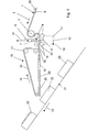
- an adhesive tape 1 which consists of a multi-layer composite, which consists in the embodiment shown of a film side 30, which may consist of paper or plastic, wherein the pressure takes place either in the space between the bottom of the film side and the glue side 8 or on the top of the film side 30 is present.
- This adhesive tape 1 is guided in the direction of arrow 3 over a first guide roller 2, and the large wrap angle, a good transport of the adhesive tape 1 is achieved.
- the guide roller 2 can be driven or not driven.
- deflection roller 2 is vertically offset and arranged above the upper roller of a first pair of rollers 4, results in a very large wrap angle for the uppermost role of the first pair of rollers 4. This undesirable slippage is substantially reduced.
- the first pair of rollers 4 thus forms the first nip 5, through which the adhesive tape 1 is transported therethrough.
- a second pair of rollers 14 is arranged, which in turn forms a second nip 13.
- the cutting device is now arranged according to the invention, which consists in the embodiment shown of a linear cutter, wherein a displaceable in the direction of arrows 31 driven cutting blade 7 is linearly movable and is guided against a fixed counter blade 6, which is arranged below the adhesive tape 1.
- the invention is not limited to the fact that the cutting blade 7 cuts on the paper side 30. It may be provided in another embodiment that counter blade and cutting blade are interchanged with each other, so that the cutting blade 7 intersects on the glue side 8 and the counter blade is arranged opposite to the paper side 30.
- all rolls of all pairs of rolls 4, 14 are driven synchronously with a single drive motor, but that the diameter of the rolls of the second roll pair 14 is slightly larger than the diameter of the rolls of the first roll pair 4.
- the diameter difference between the diameter of the rollers of the first pair of rollers 4 and the rollers of the second pair of rollers 14 is in the range of 0.1 to 5%.
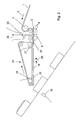
- the cut label 18 is further promoted in the direction of arrow 3 against a transfer device 15, which consists in the embodiment shown of a suction belt 32, which in Arrow direction 16 is driven and which is guided over the pulleys 17, 33, 34.
- suction belt operating with vacuum
- transfer belt operating with electrostatic attractive forces and the like.
- the drive speed at the deflection rollers 17, 33, 34 (in the direction of arrow 16) is selected to be slightly greater than the speed with which the cut-off label 18 leaves the second nip 14. This ensures that the cut-off label 18 is always pulled lightly during transfer to the transfer device and never pushed.
- the now cut label 20 is applied to a product 22, which is guided in the direction of arrow 23 on a conveyor belt 21.
- the sensor 35 detects the presence of the product 22 on the conveyor belt 21. It thus triggers the labeling process and the start of the drive of the transfer device 15.
- the leading edge of the foremost label 20 in FIG. 2 meets the top of the product 22 when the speed of the transfer device in the direction of arrow 16 is synchronous with the speed in the direction of arrow 23 on the conveyor belt 21.
- the drive of the transfer device 15 stops when the leading edge of the subsequent label 19 comes into the region of the sensor 28.
- the control of the drive for the transmission device 15 has incorporated a certain delay time.
- the sensor 25 detects a print mark on the adhesive tape 1 and upon detection of this print mark, the entire drive of the roller pairs 4, 14 is stopped. Immediately after stopping is cut, the cutting operation (movement of the cutting blade 7) is detected by the sensor 26.
- the sensor 26 has the task of recognizing the lowered cutting blade and starts the further feed drive of the roller pairs 4, 14, when the cutting blade 7 has been released from the adhesive tape 1 again.
- the sensor 25 does not only have to recognize a print mark, but other recognition features can also be provided on the adhesive tape 1, to which the sensor 25 reacts.
- a guide track 24 is provided for supporting storage of the cut-off label 18.
- Such guideways 24 may also be arranged at other locations of the transport process of the adhesive tape 1.
- such a guideway can also be provided upstream of the first pair of rollers 4.
- Such a guideway may also be arranged between the roller pairs in the region of the cutting device.
- the speed of the transmission device 15 is synchronized with the speed of the conveyor belt 21. If, for example, the speed of the conveyor belt 21 is reduced and thus the flow of the products 22 past the labeling device, then the speed of a transfer device 15 is also reduced in order to always achieve a synchronous movement when gluing a label 20 onto the product 22. This will prevent a label from being creased onto the product.
Abstract
Description
Gegenstand der Erfindung ist ein Etikettierautomat für Linerless-Etiketten nach dem Oberbegriff des Patentanspruchs 1.The invention relates to a labeller for linerless labels according to the preamble of patent claim 1.
Mit dem Gegenstand der
Es handelt sich hierbei jedoch nicht um Vorspannmittel zur Erzeugung einer Zugspannung in Längsrichtung des Klebebandes, sondern lediglich darum, dass ein Haltemittel vorgesehen wird, um ein unbeabsichtigtes und unerwünschtes Herausfallen des abgeschnittenen Etikettes nach unten zu verhindern.However, this is not to bias means for generating a tensile stress in the longitudinal direction of the adhesive tape, but only that a holding means is provided to prevent accidental and unwanted falling out of the cut label down.
Mit dem Gegenstand der
Die genannte Vorrichtung schneidet deshalb nicht im Stillstand, sondern während des Vorschubes des Etikettenbandes.Therefore, said device does not cut at a standstill, but during the advancement of the label tape.
Der gleiche Nachteil gilt im Übrigen auch für den Gegenstand der
Der Erfindung liegt deshalb ausgehend von der
Zur Lösung der gestellten Aufgabe ist die Erfindung durch die technische Lehre des Anspruches 1 gekennzeichnet.To solve the problem, the invention is characterized by the technical teaching of claim 1.
Wesentliches Merkmal der Erfindung ist, dass stromaufwärts und stromabwärts ein Walzenpaar angeordnet ist, so dass das Schneidmesser im Zwischenraum zwischen einem ersten und einem zweiten Walzenpaar angeordnet ist, und dass eine Zugspannung auf das abzuschneidende Klebeband im Bereich der Schneideinrichtung zwischen dem ersten und dem zweiten Walzenspalt des ersten und zweiten Walzenpaares erzeugt wird.An essential feature of the invention is that upstream and downstream of a pair of rollers is arranged so that the cutting blade is arranged in the space between a first and a second pair of rollers, and that a tensile stress on the cut off tape in the region of the cutting device between the first and the second nip of the first and second roller pair is generated.
Mit der gegebenen technischen Lehre ergibt sich der wesentliche Vorteil, dass nun erstmals auf rotierende Schneidmesser verzichtet werden kann und stattdessen ein linear bewegbares Schneidmesser verwendet werden kann, welches den Vorteil besitzt, dass bei stehendem Klebeband geschnitten werden kann. Damit ergibt sich ein besonders genauer präziser Schnitt, der zuverlässig an der gewünschten Stelle des Klebebandes erfolgt, ohne dass große Toleranzabstände gegeben sind.With the given technical teaching, there is the significant advantage that rotary cutting blades can now be dispensed with for the first time and instead a linearly movable cutting blade can be used, which has the advantage that it can be cut when the adhesive tape is stationary. This results in a particularly accurate precise cut, which takes place reliably at the desired location of the adhesive tape, without large tolerance intervals are given.
Damit ergibt sich eine hohe Schnittgenauigkeit und eine präzise Übergabe des geschnittenen Etikettes auf eine nachgeschaltete Übertragungsvorrichtung.This results in a high accuracy of cut and a precise transfer of the cut label on a downstream transfer device.
Damit ist es nun erstmals möglich, besonders präzise geschnittene Etiketten auf eine Übertragungsvorrichtung zu bringen.This now makes it possible for the first time to bring particularly precisely cut labels onto a transfer device.
Nach einem weiteren Merkmal der Erfindung ist es vorgesehen, dass die Übernahmegeschwindigkeit der Übertragungsvorrichtung geringfügig größer oder gleich der Abgabegeschwindigkeit des zweiten auslaufseitig der Schneideinrichtung angeordneten Walzenspaltes ist.According to a further feature of the invention, it is provided that the transfer speed of the transfer device is slightly greater than or equal to the delivery speed of the second outlet side of the cutting device arranged nip.
Damit wird gewährleistet, dass die Übertragungsvorrichtung die aus dem zweiten Walzenspalt auslaufenden, geschnittenen Etiketten ohne Gefahr des Aufstauens und Zerknitterns erhält und die Etiketten hierbei gleichzeitig noch auf Abstand aufgebracht werden, so dass ein bestimmter vordefinierter Abstand zwischen den einzelnen Etiketten an der Übertragungsvorrichtung gewährleistet ist.This ensures that the transfer device receives the discontinued from the second nip, cut labels without risk of damming and crumpling and the labels are hereby still applied at a distance, so that a certain predefined distance between the individual labels is ensured on the transmission device.
Wichtig hierbei ist, dass die Schneideinrichtung zwischen dem ersten und dem zweiten Walzenpaar angeordnet ist und im Stand geschnitten wird. Damit wird erreicht, dass das Etikett sich während des Schneidens nicht verkantet und verzieht, weil es durch den auslaufseitigen zweiten Walzenspalt gehalten und fixiert wird.It is important here that the cutting device is arranged between the first and the second roller pair and is cut in the state. This ensures that the label is not tilted and distorted during cutting, because it is held and fixed by the outlet side second nip.
Dies ist ein wesentlicher Vorteil gegenüber dem Stand der Technik, insbesondere der
Bei der vorliegenden Erfindung ist nicht entscheidend, wie die Zugspannung zwischen dem ersten und dem zweiten Walzenspalt erzeugt wird, mit dem Ziel, das abzuschneidende Klebeband im Bereich der Schneideinrichtung unter Zugspannung zu setzen. Es gibt hierbei verschiedene Möglichkeiten, die in Kombination oder in Einzelstellung untereinander als erfindungswesentlich beansprucht werden.In the present invention, it is not critical how the tensile stress is generated between the first and second nip, with the aim of tensioning the adhesive tape to be cut off in the region of the cutting device. There are various possibilities that are claimed in combination or in individual position with each other as essential to the invention.
Nach einer ersten Ausführungsform wird es bevorzugt, wenn lediglich der erste einlaufseitige Walzenspalt angetrieben ist, wobei es wiederum gleichgültig ist, ob von dem Walzenspalt lediglich eine Walze des Walzenpaares angetrieben ist oder beide Walzen dieses Walzenpaares synchron angetrieben sind.According to a first embodiment, it is preferred if only the first inlet side nip is driven, again it is irrelevant whether only one roller of the roller pair is driven by the roller nip or both rollers of this roller pair are driven synchronously.
Gleiches gilt auch für das auslaufseitig angeordnete zweite Walzenpaar, welches dem zweiten Walzenspalt dient.The same applies to the outlet side arranged second pair of rollers, which serves the second nip.
Hierbei kann es ebenso vorgesehen sein, dass dieses zweite Walzenpaar angetrieben ist und die Antriebsgeschwindigkeit dieses zweiten Walzenpaars geringfügig größer ist als die Antriebsgeschwindigkeit des ersten Walzenpaars.It can also be provided that this second pair of rollers is driven and the drive speed of this second pair of rollers is slightly larger than the drive speed of the first pair of rollers.
In einer weiteren Ausbildung der vorliegenden Erfindung ist es vorgesehen, dass alle vier Walzen der beiden Walzenpaare synchron durch einen einzigen Antriebsmotor angetrieben sind. Damit ergibt sich der Vorteil eines besonders kostengünstigen Antriebes und die gewünschte Zugspannung wird nun erfindungsgemäß dadurch erzielt, dass der Durchmesser der Walzen des zweiten Walzenspaltes geringfügig größer ist als der Durchmesser der Walzen des ersten Walzenspaltes.In a further embodiment of the present invention, it is provided that all four rollers of the two pairs of rollers are driven synchronously by a single drive motor. This results in the advantage of a particularly cost-effective drive and the desired tensile stress is now inventively achieved in that the diameter of the rollers of the second nip is slightly larger than the diameter of the rollers of the first nip.
Damit wird - wegen der erzielten größeren Umfangsgeschwindigkeit - eine Zugspannung auf das abzuschneidende Klebeband erzeugt, ohne dass es weiterer Antriebsmittel oder Regelungsmittel bedarf. Es handelt sich demzufolge um eine besonders einfache und betriebssichere Anordnung.This is - because of the achieved greater peripheral speed - a tensile stress on the tape to be cut off, without the need for further drive means or control means. It is therefore a particularly simple and reliable arrangement.
Nach einer Weiterbildung der vorliegenden Erfindung kann es auch vorgesehen sein, dass der einzige Antriebsmotor nicht alle vier Walzen der beiden Walzenpaare synchron antreibt, sondern lediglich nur beispielsweise die jeweilige obere Walze oder jeweilige untere Walze des jeweiligen Walzenpaares.According to a development of the present invention, it can also be provided that the single drive motor does not synchronously drive all four rollers of the two roller pairs, but only for example the respective upper roller or respective lower roller of the respective roller pair.
Der synchrone Antrieb aller vier Walzen wird jedoch bevorzugt, weil damit verhindert wird, dass der Leim, der über eine Walze jeweils eines Walzenpaares läuft, nicht zu einem unzulässigen und unerwünschten Schlupf am Klebeband führt.However, the synchronous drive of all four rolls is preferred because it prevents the glue, which passes over a roll, in each case one roll pair runs, does not lead to an unacceptable and unwanted slip on the tape.
Wenn nämlich - wie hier vorgesehen - im Start-Stop-Betrieb gearbeitet wird, könnte ein Schlupf einer nicht angetriebenen Walze im Bereich der Klebstoffschicht zu einer unerwünschten Veränderung der Struktur der Klebstoffschicht führen und damit eine optisch sichtbare und unerwünschte Markierung auf der Klebstoffschicht bei dem später aufgeklebten Etikett verursachen.Namely, if - as provided here - is used in start-stop operation, a slippage of a non-driven roller in the adhesive layer could lead to an undesirable change in the structure of the adhesive layer and thus an optically visible and undesirable mark on the adhesive layer in the later cause sticked label.
Mit der gegebenen technischen Lehre der Erfindung ergibt sich der Vorteil, dass nun erstmals ein Etikettierautomatt für Linerless-Etiketten mit einer Leistung von bis zu 240 Schneidvorgängen und Etikettierungen pro Minute erreicht werden kann. Durch zwei Doppelwalzen mit unterschiedlichem Durchmesser wird das Klebeband für das Schneiden gespannt. Bevorzugt sind alle vier Walzen angetrieben und der Schneidapparat kann bis zu 170 Millimeter breite Etiketten schneiden, wobei bisher nur 100 Millimeter breite Etiketten geschnitten werden konnten. Dies liegt daran, dass eben verkantungsfrei derartig breite Etiketten durch den zweiten auslaufseitig angeordneten Walzenspalt fixiert werden, wodurch eben auch breite Etiketten geschnitten werden können.With the given technical teaching of the invention there is the advantage that now for the first time a labeling machine for linerless labels with an output of up to 240 cutting operations and labeling per minute can be achieved. Two double rolls of different diameter stretch the adhesive tape for cutting. Preferably, all four rollers are driven and the cutting device can cut labels up to 170 millimeters in width, whereby previously only 100 millimeters wide labels could be cut. This is due to the fact that such wide labels are fixed without jamming by the second nip arranged on the outlet side, whereby even wide labels can be cut.
Durch die Verwendung eines linear bewegten Messers, das gegen ein festes Gegenmesser schneidet, ist das feste Gegenmesser freiliegend und daher besteht nur eine geringe Gefahr, dass sich dort Klebstoff anlagert, wodurch eine lange Betriebsdauer der Schneidvorrichtung gegeben ist.By using a linearly moving knife that cuts against a fixed counter knife, the fixed counter knife is exposed and therefore there is little risk that there adhesive attaches, whereby a long service life of the cutting device is given.
Der Erfindungsgegenstand der vorliegenden Erfindung ergibt sich nicht nur aus dem Gegenstand der einzelnen Patentansprüche, sondern auch aus der Kombination der einzelnen Patentansprüche untereinander.The subject of the present invention results not only from the subject matter of the individual claims, but also from the combination of the individual claims with each other.
Alle in den Unterlagen, einschließlich der Zusammenfassung offenbarten Angaben und Merkmale, insbesondere die in den Zeichnungen dargestellte räumliche Ausbildung, werden als erfindungswesentlich beansprucht, soweit sie einzeln oder in Kombination gegenüber dem Stand der Technik neu sind.All information and features disclosed in the documents, including the abstract, in particular the spatial design shown in the drawings, are claimed to be essential to the invention insofar as they are novel individually or in combination with respect to the prior art.
Im Folgenden wird die Erfindung anhand von lediglich einen Ausführungsweg darstellenden Zeichnungen näher erläutert. Hierbei gehen aus den Zeichnungen und ihrer Beschreibung weitere erfindungswesentliche Merkmale und Vorteile der Erfindung hervor.In the following the invention will be explained in more detail with reference to drawings showing only one embodiment. Here are from the drawings and their description further features essential to the invention and advantages of the invention.
- Figur 1:FIG. 1:
- schematisiert im Schnitt die Darstellung eines Etikettierautomaten nach der Erfindungschematically shows in section the representation of a labeling machine according to the invention
- Figur 2:FIG. 2:
-
die gleiche Darstellung wie
Figur 1 mit Eintragung weiterer Einzelheitenthe same representation asFIG. 1 with entry of further details
In den
Dieses Klebeband 1 wird in Pfeilrichtung 3 über eine erste Umlenkwalze 2 geführt, und durch den großen Umschlingungswinkel wird ein guter Transport des Klebebandes 1 erreicht.This adhesive tape 1 is guided in the direction of
Die Umlenkwalze 2 kann hierbei angetrieben oder nicht angetrieben ausgebildet sein.The
Dadurch, dass die Umlenkwalze 2 vertikal versetzt und oberhalb der oberen Rolle eines ersten Walzenpaares 4 angeordnet ist, ergibt sich ein sehr großer Umschlingungswinkel für die oberste Rolle des ersten Walzenpaares 4. Dadurch wird ein unerwünschter Schlupf wesentlich verringert.The fact that the
Das erste Walzenpaar 4 bildet somit den ersten Walzenspalt 5, durch den das Klebeband 1 hindurchtransportiert wird.The first pair of
Wichtig ist, dass nun stromab des ersten Walzenpaares 4 ein zweites Walzenpaar 14 angeordnet ist, welches wiederum einen zweiten Walzenspalt 13 ausbildet. Zwischen dem ersten Walzenpaar 4 und dem zweiten Walzenpaar 14 ist nun erfindungsgemäß die Schneideinrichtung angeordnet, die im gezeigten Ausführungsbeispiel aus einer linearen Schneideinrichtung besteht, wobei ein in den Pfeilrichtungen 31 verschiebbar angetriebenes Schneidmesser 7 linear bewegbar ist und hierbei gegen ein feststehendes Gegenmesser 6 geführt ist, welches unterhalb des Klebebandes 1 angeordnet ist.It is important that now downstream of the first pair of
Die Erfindung ist hierbei nicht darauf beschränkt, dass das Schneidmesser 7 auf der Papierseite 30 schneidet. Es kann in einer anderen Ausführungsform vorgesehen sein, dass Gegenmesser und Schneidmesser gegeneinander vertauscht sind, so dass das Schneidmesser 7 auf der Leimseite 8 schneidet und das Gegenmesser dem gegenüberliegend auf der Papierseite 30 angeordnet ist.The invention is not limited to the fact that the
Wichtig ist nun, dass bezüglich der Achsen der beiden Walzenpaare 4, 14 (gekennzeichnet durch die Positionen 10 und 11) eine Zugspannung 12 erzeugt wird.It is important now that with respect to the axes of the two
Nach einer bevorzugten Ausführungsform der Erfindung ist es hierbei vorgesehen, dass alle Walzen aller Walzenpaare 4, 14 synchron mit einem einzigen Antriebsmotor angetrieben sind, dass jedoch der Durchmesser der Walzen des zweiten Walzenpaares 14 geringfügig größer ist als der Durchmesser der Walzen des ersten Walzenpaares 4. Die Durchmesserdifferenz zwischen dem Durchmesser der Walzen des ersten Walzenpaares 4 und den Walzen des zweiten Walzenpaares 14 liegt hierbei im Bereich von 0,1 bis 5%.According to a preferred embodiment of the invention, it is provided here that all rolls of all pairs of
Bei Position 9 ist im Übrigen ein Sensor angeordnet, der im Zusammenhang mit
Nachdem das Etikett abgeschnitten wurde, wird das geschnittene Etikett 18 weiter in Pfeilrichtung 3 gegen eine Übertragungsvorrichtung 15 gefördert, die im gezeigten Ausführungsbeispiel aus einem Saugband 32 besteht, welches in Pfeilrichtung 16 angetrieben wird und welches über die Umlenkrollen 17, 33, 34 geführt ist.After the label has been cut, the
Statt einem mit Vakuum arbeitenden Saugband können auch andere Übertragungsvorrichtungen verwendet werden, insbesondere ein mit elektrostatischen Anziehungskräften arbeitendes Übertragungsband und dergleichen mehr.Instead of a suction belt operating with vacuum, other transmission devices may also be used, in particular a transfer belt operating with electrostatic attractive forces and the like.
Wichtig hierbei ist, dass die Antriebsgeschwindigkeit an den Umlenkrollen 17, 33, 34 (in Pfeilrichtung 16) geringfügig größer gewählt ist als die Geschwindigkeit mit der das abgeschnittene Etikett 18 den zweiten Walzenspalt 14 verlässt. Damit wird gewährleistet, dass das abgeschnittene Etikett 18 bei der Übergabe auf die Übertragungsvorrichtung immer leicht gezogen und nie gestoßen wird.It is important that the drive speed at the
Damit wird eine exakte Positionierung der Etikette 18 auf dem Saugband ohne seitliches Verschieben respektive Verkanten erreicht.Thus, an exact positioning of the
Durch die Wahl der Abnahmegeschwindigkeit der Übertragungsvorrichtung 15 im Vergleich zur Abgabegeschwindigkeit des zweiten Walzenspaltes 14 wird gewährleistet, dass die abgeschnittenen Etiketten 18-20 sich niemals auf dem Saugband 32 aufschieben.By choosing the rate of decrease of the
Es soll also stets dafür gesorgt werden, dass ein Abstand 29 zwischen den einzelnen aufeinanderfolgenden Etiketten 18-20 vorhanden ist.It should therefore always be ensured that a
Im Bereich der vorderen Umlenkrolle 34 wird das nun geschnittene Etikett 20 auf ein Produkt 22 appliziert, welches in Pfeilrichtung 23 auf einem Transportband 21 vorbeigeführt wird.In the area of the front deflection roller 34, the now cut
Es wird hierbei ein Gleichlauf der Applikation des geschnittenen Etiketts 20 mit dem Produkt 22 in Pfeilrichtung 23 erreicht. Dies wird anhand der
Der Sensor 35 erkennt die Anwesenheit des Produktes 22 auf dem Transportband 21. Er löst damit den Etikettierprozess und den Start des Antriebes der Übertragungsvorrichtung 15 aus. Die Vorderkante des vordersten Etikettes 20 in
Mit dem Sensor 27 erfolgt eine Stauüberwachung, d. h. damit wird der jeweilige Abstand 29 zwischen den einzelnen abgeschnittenen Etiketten überwacht.With the
Mit dem Sensor 25 wird die Schneideinrichtung angesteuert.With the
Der Sensor 25 erkennt eine Druckmarke auf dem Klebeband 1 und bei Erkennen dieser Druckmarke wird der gesamte Antrieb der Walzenpaare 4, 14 stillgesetzt. Unmittelbar nach dem Stillsetzen wird geschnitten, wobei der Schneidvorgang (Bewegung des Schneidmessers 7) durch den Sensor 26 erkannt wird.The
Der Sensor 26 hat die Aufgabe, das abgesenkte Schneidmesser zu erkennen und startet den weiteren Vorschubantrieb der Walzenpaare 4, 14 dann, wenn sich das Schneidmesser 7 aus dem Klebeband 1 wieder gelöst hat.The
Der Sensor 25 muss nicht nur eine Druckmarke erkennen, sondern es können auch andere Erkennungsmerkmale auf dem Klebeband 1 vorgesehen werden, auf die der Sensor 25 reagiert.The
Ebenso ist nur beispielhaft dargestellt, dass am Auslauf des zweiten Walzenpaares 14 eine Führungsbahn 24 zur unterstützenden Lagerung des abgeschnittenen Etikettes 18 vorgesehen ist.Likewise, it is only shown by way of example that at the outlet of the second pair of
Derartige Führungsbahnen 24 können auch an anderen Stellen des Transportablaufes des Klebebandes 1 angeordnet sein. Insbesondere kann eine solche Führungsbahn auch einlaufseitig vor dem ersten Walzenpaar 4 vorgesehen sein.
Ferner kann eine solche Führungsbahn auch zwischen den Walzenpaaren im Bereich der Schneideinrichtung angeordnet sein.Furthermore, such a guideway may also be arranged between the roller pairs in the region of the cutting device.
Nach einem weiteren bevorzugten Merkmal der Erfindung ist es vorgesehen, dass auch die Geschwindigkeit der Übertragungsvorrichtung 15 mit der Geschwindigkeit des Transportbandes 21 synchronisiert ist. Wird beispielsweise die Geschwindigkeit des Transportbandes 21 verringert und damit der Fluss der Produkte 22 an der Etikettiereinrichtung vorbei, dann wird somit auch die Geschwindigkeit einer Übertragungsvorrichtung 15 verringert, um stets eine synchrone Bewegung beim Aufkleben eines Etikettes 20 auf das Produkt 22 zu erreichen. Damit wird verhindert, dass ein Etikett unter Faltenbildung auf das Produkt aufgeklebt wird.According to a further preferred feature of the invention, it is provided that the speed of the
Im Übrigen wird in der vorliegenden Erfindung auch als erfindungswesentlich beansprucht, statt eines linear bewegten mechanischen Schneidmessers 7 mit einem Gegenmesser 6 auch andere Schneidvorrichtungen zu beanspruchen, nämlich insbesondere Laser-Schneideinrichtungen oder ein Rotationsmesser, unter der Voraussetzung, dass das Rotationsmesser im Zwischenraum zwischen einer eine Zugspannung ausübenden Einrichtung bestehend aus zwei voneinander beabstandeten Walzenpaaren angeordnet ist.Incidentally, claimed in the present invention as essential to the invention, instead of a linearly moving
- 11
- Klebebandduct tape
- 22
- Umlenkwalzedeflecting
- 33
- Pfeilrichtungarrow
- 44
- erstes Walzenpaarfirst pair of rollers
- 55
- Walzenspaltnip
- 66
- Gegenmesseragainst knife
- 77
- Schneidmessercutting blade
- 88th
- Leimseiteglue side
- 99
- Positionposition
- 1010
- Positionposition
- 1111
- Positionposition
- 1212
- Zugspannungtension
- 1313
- Walzenspaltnip
- 1414
- zweites Walzenpaarsecond pair of rollers
- 1515
- Übertragungsvorrichtungtransfer device
- 1616
- Pfeilrichtungarrow
- 1717
- Umlenkrolleidler pulley
- 1818
- geschnittenes Etikettcut label
- 1919
- geschnittenes Etikettcut label
- 2020
- geschnittenes Etikettcut label
- 2121
- Transportbandconveyor belt
- 2222
- Produktproduct
- 2323
- Pfeilrichtungarrow
- 2424
- Führungsbahnguideway
- 2525
- Sensorsensor
- 2626
- Sensorsensor
- 2727
- Sensorsensor
- 2828
- Sensorsensor
- 2929
- Abstanddistance
- 3030
- Folienseitefilm side
- 3131
- Pfeilrichtungarrow
- 3232
- Saugbandsuction belt
- 3333
- Umlenkrolleidler pulley
- 3434
- Umlenkrolleidler pulley
- 3535
- Sensorsensor
Claims (10)
Applications Claiming Priority (1)
| Application Number | Priority Date | Filing Date | Title |
|---|---|---|---|
| DE102007058765A DE102007058765A1 (en) | 2007-12-06 | 2007-12-06 | Labeling machine for linerless labels |
Publications (2)
| Publication Number | Publication Date |
|---|---|
| EP2067702A1 true EP2067702A1 (en) | 2009-06-10 |
| EP2067702B1 EP2067702B1 (en) | 2011-11-23 |
Family
ID=40418897
Family Applications (1)
| Application Number | Title | Priority Date | Filing Date |
|---|---|---|---|
| EP08019401A Revoked EP2067702B1 (en) | 2007-12-06 | 2008-11-06 | Automatic labelling machine for linerless labels |
Country Status (4)
| Country | Link |
|---|---|
| US (1) | US20090145558A1 (en) |
| EP (1) | EP2067702B1 (en) |
| AT (1) | ATE534580T1 (en) |
| DE (1) | DE102007058765A1 (en) |
Cited By (6)
| Publication number | Priority date | Publication date | Assignee | Title |
|---|---|---|---|---|
| EP2210814A3 (en) * | 2009-01-21 | 2011-03-23 | Seiko Instruments Inc. | Adhesive label manufacturing device and adhesive label manufacturing method |
| EP2679506A1 (en) * | 2012-06-26 | 2014-01-01 | MULTIVAC Marking & Inspection GmbH & Co. KG | Label transport belt |
| EP2679505A1 (en) * | 2012-06-26 | 2014-01-01 | MULTIVAC Marking & Inspection GmbH & Co. KG | Labelling device with conveyor belt |
| WO2015010868A1 (en) * | 2013-07-23 | 2015-01-29 | Khs Gmbh | Label-feeding apparatus and labelling apparatus |
| EP2634105B1 (en) | 2010-10-29 | 2017-01-04 | Fuji Seal International, Inc. | Label producing device |
| CN110603217A (en) * | 2017-03-22 | 2019-12-20 | 德莎欧洲股份公司 | Applicator for stamping parts |
Families Citing this family (11)
| Publication number | Priority date | Publication date | Assignee | Title |
|---|---|---|---|---|
| EP2442915A4 (en) * | 2009-06-14 | 2016-07-20 | Nulabel Technologies Inc | Liner-free label and systems |
| JP2011213407A (en) * | 2010-04-01 | 2011-10-27 | Toppan Tdk Label Co Ltd | Sticking apparatus |
| JP5591653B2 (en) * | 2010-10-27 | 2014-09-17 | 東和精工株式会社 | Label peeling machine |
| DE102012207321A1 (en) * | 2012-05-03 | 2013-11-07 | Robert Bosch Gmbh | Transport device with improved adhesive properties |
| BR112015024217A2 (en) | 2013-04-26 | 2017-07-18 | Avery Dennison Corp | apparatus for dispensing pressure sensitive adhesive labels onto a substrate |
| DE102014110144A1 (en) | 2014-07-18 | 2016-01-21 | Krones Ag | Labeling device for carrierless label strips |
| WO2016164717A1 (en) * | 2015-04-08 | 2016-10-13 | Jtco, Llc | Ground based label application apparatus and method |
| DE102017105154B4 (en) | 2017-03-10 | 2019-02-21 | Baumann Gmbh | Apparatus and method for severing a tape into a plurality of individual tape pieces |
| DE102018200439A1 (en) * | 2018-01-12 | 2019-07-18 | Tesa Se | Stamped part applicator and method for applying stamped parts to surfaces and a stamped part strip |
| US11249338B2 (en) * | 2019-07-08 | 2022-02-15 | Rockwell Collins, Inc. | Flexible to rigid integrated laminator |
| CN114506730B (en) * | 2022-01-20 | 2023-11-07 | 东台骏兴科技有限公司 | Automatic labeling, conveying and stacking machine |
Citations (7)
| Publication number | Priority date | Publication date | Assignee | Title |
|---|---|---|---|---|
| US3865671A (en) * | 1971-09-10 | 1975-02-11 | Hermann Kronseder | Labeling device for upright standing objects |
| EP0858422A1 (en) * | 1995-10-31 | 1998-08-19 | Moores Business Forms, Inc. | Separator for linerless labels |
| DE69617386T2 (en) | 1995-09-15 | 2002-07-25 | Moore Business Forms Inc | SEMI-AUTOMATIC DISPENSER FOR STRAPLESS LABELS |
| GB2379918A (en) * | 2001-09-21 | 2003-03-26 | Sovereign Labelling Sys Ltd | Labelling Machine |
| WO2005023654A1 (en) | 2003-09-11 | 2005-03-17 | Promark Produkcja Sp. Z O.O. | Method for labeling items |
| DE10351877A1 (en) | 2003-10-29 | 2005-06-09 | Bizerba Gmbh & Co. Kg | Cutting device for cutting off labels from a linerless adhesive band, especially for use with a print device, has a counter knife that is moved away from the adhesive label band during transport and moved against it during cutting |
| US7293592B1 (en) * | 2003-03-03 | 2007-11-13 | George Schmitt & Co., Inc | Forming and applying linerless labels |
Family Cites Families (15)
| Publication number | Priority date | Publication date | Assignee | Title |
|---|---|---|---|---|
| US2678748A (en) * | 1950-11-10 | 1954-05-18 | Mccain | Mailing machine |
| US3938698A (en) * | 1974-11-27 | 1976-02-17 | Avery Products Corporation | Apparatus for dispensing adhesive labels |
| US4397410A (en) * | 1978-07-07 | 1983-08-09 | Swingline Inc. | Burster |
| JPS56158000A (en) * | 1980-05-06 | 1981-12-05 | Nippon Telegraph & Telephone | Cutter for blank form |
| DE3509987A1 (en) * | 1985-03-20 | 1986-10-02 | Krones Ag Hermann Kronseder Maschinenfabrik, 8402 Neutraubling | Labelling apparatus for vessels or the like |
| EP0414056A3 (en) * | 1989-08-23 | 1991-06-12 | Dennison Danmark A/S | Process and device for labelling articles |
| CA2106714A1 (en) * | 1993-09-21 | 1995-03-22 | Robert S. Ring | Apparatus and methods for bursting interstacked longitudinally offset form sets from continuous webs |
| US5540369A (en) * | 1993-12-07 | 1996-07-30 | Moore Business Forms, Inc. | Detaching linerless labels |
| JP3859862B2 (en) * | 1998-04-20 | 2006-12-20 | セントラル硝子株式会社 | Adhesive tape application method and apparatus |
| JP2001328186A (en) * | 2000-03-17 | 2001-11-27 | Matsuzaki:Kk | Method and equipment for cutting original paper of label |
| FR2814839B1 (en) * | 2000-09-29 | 2003-02-28 | Neopost Ind | MULTIPURPOSE POSTAGE MACHINE |
| FR2817837B1 (en) * | 2000-12-13 | 2003-08-08 | Neopost Ind | STRIP LABEL DISTRIBUTOR |
| US20020144770A1 (en) * | 2001-04-06 | 2002-10-10 | Stephane Mabit | Carrier-less patch protection including cassette and separation process |
| JP2004175390A (en) * | 2002-11-26 | 2004-06-24 | Seiko Epson Corp | Thermosensitive adhesive activation device |
| DE102006019265A1 (en) * | 2006-04-26 | 2008-01-17 | Khs Ag | Device for dispensing labels, in particular self-adhesive labels, onto objects |
-
2007
- 2007-12-06 DE DE102007058765A patent/DE102007058765A1/en not_active Withdrawn
-
2008
- 2008-11-06 AT AT08019401T patent/ATE534580T1/en active
- 2008-11-06 EP EP08019401A patent/EP2067702B1/en not_active Revoked
- 2008-12-08 US US12/330,429 patent/US20090145558A1/en not_active Abandoned
Patent Citations (7)
| Publication number | Priority date | Publication date | Assignee | Title |
|---|---|---|---|---|
| US3865671A (en) * | 1971-09-10 | 1975-02-11 | Hermann Kronseder | Labeling device for upright standing objects |
| DE69617386T2 (en) | 1995-09-15 | 2002-07-25 | Moore Business Forms Inc | SEMI-AUTOMATIC DISPENSER FOR STRAPLESS LABELS |
| EP0858422A1 (en) * | 1995-10-31 | 1998-08-19 | Moores Business Forms, Inc. | Separator for linerless labels |
| GB2379918A (en) * | 2001-09-21 | 2003-03-26 | Sovereign Labelling Sys Ltd | Labelling Machine |
| US7293592B1 (en) * | 2003-03-03 | 2007-11-13 | George Schmitt & Co., Inc | Forming and applying linerless labels |
| WO2005023654A1 (en) | 2003-09-11 | 2005-03-17 | Promark Produkcja Sp. Z O.O. | Method for labeling items |
| DE10351877A1 (en) | 2003-10-29 | 2005-06-09 | Bizerba Gmbh & Co. Kg | Cutting device for cutting off labels from a linerless adhesive band, especially for use with a print device, has a counter knife that is moved away from the adhesive label band during transport and moved against it during cutting |
Cited By (8)
| Publication number | Priority date | Publication date | Assignee | Title |
|---|---|---|---|---|
| EP2210814A3 (en) * | 2009-01-21 | 2011-03-23 | Seiko Instruments Inc. | Adhesive label manufacturing device and adhesive label manufacturing method |
| US8616878B2 (en) | 2009-01-21 | 2013-12-31 | Seiko Instruments Inc. | Adhesive label manufacturing device and adhesive label manufacturing method |
| EP2634105B1 (en) | 2010-10-29 | 2017-01-04 | Fuji Seal International, Inc. | Label producing device |
| EP2679506A1 (en) * | 2012-06-26 | 2014-01-01 | MULTIVAC Marking & Inspection GmbH & Co. KG | Label transport belt |
| EP2679505A1 (en) * | 2012-06-26 | 2014-01-01 | MULTIVAC Marking & Inspection GmbH & Co. KG | Labelling device with conveyor belt |
| WO2015010868A1 (en) * | 2013-07-23 | 2015-01-29 | Khs Gmbh | Label-feeding apparatus and labelling apparatus |
| US10293967B2 (en) | 2013-07-23 | 2019-05-21 | Khs Gmbh | Label-feeding apparatus and labelling apparatus |
| CN110603217A (en) * | 2017-03-22 | 2019-12-20 | 德莎欧洲股份公司 | Applicator for stamping parts |
Also Published As
| Publication number | Publication date |
|---|---|
| EP2067702B1 (en) | 2011-11-23 |
| US20090145558A1 (en) | 2009-06-11 |
| ATE534580T1 (en) | 2011-12-15 |
| DE102007058765A1 (en) | 2009-06-25 |
Similar Documents
| Publication | Publication Date | Title |
|---|---|---|
| EP2067702B1 (en) | Automatic labelling machine for linerless labels | |
| EP1282510B1 (en) | Method and device for cutting a laminate | |
| EP1904390B1 (en) | Device and method for splicing strips of labels | |
| EP0031515B1 (en) | Apparatus for producing packaging blanks by separation from a continuously moving web | |
| EP0040831B1 (en) | Labelling machine | |
| DE3218304A1 (en) | DEVICE FOR SEPARATING CONTINUOUS FORM SETS OR THE LIKE. | |
| EP2093057B1 (en) | Method and apparatus for removing used stamping foil | |
| EP0557609B1 (en) | Apparatus for on line controlling of foldable box blanks | |
| EP0176789A2 (en) | Method and device for changing web rolls in connection with packaging machines | |
| DE2644462A1 (en) | LABELING SYSTEM | |
| EP2383117A1 (en) | Method and apparatus for coating a sheet-shaped carrier material | |
| EP0623458B1 (en) | Method and apparatus for applying adhesive on paper and/or plastic products | |
| WO1997011019A1 (en) | Process and device for producing printed matter | |
| DE2217032C3 (en) | Device for applying blanks made from a continuous web to objects | |
| DE19504219C1 (en) | Packaging machine | |
| EP2227428B1 (en) | Method and apparatus for transporting paper in a paper-handling system from a first transport means to a second transport means | |
| DE3002092A1 (en) | DEVICE FOR FEEDING BAND-SHAPED PACKING MATERIAL | |
| EP0384221B1 (en) | Device for applying reinforcement patches provided with glue to a web provided with transverse perforations | |
| DE19624277C2 (en) | Device for cutting paper webs | |
| EP2657142A1 (en) | Method and device for handling folded products | |
| EP2185329A1 (en) | Device and method for cutting a paper web | |
| EP0014858A1 (en) | Method and device for attaching tear strips or the like to a web of wrapping material | |
| EP2004529B1 (en) | Apparatus and method for spatially orienting blanks | |
| DE19654986C2 (en) | Paper strip cutter with loop buffer and oscillation damper | |
| DE102022109965A1 (en) | Method and reel changer for a flying reel change as well as substrate handling and/or processing machine with a reel changer |
Legal Events
| Date | Code | Title | Description |
|---|---|---|---|
| PUAI | Public reference made under article 153(3) epc to a published international application that has entered the european phase |
Free format text: ORIGINAL CODE: 0009012 |
|
| AK | Designated contracting states |
Kind code of ref document: A1 Designated state(s): AT BE BG CH CY CZ DE DK EE ES FI FR GB GR HR HU IE IS IT LI LT LU LV MC MT NL NO PL PT RO SE SI SK TR |
|
| AX | Request for extension of the european patent |
Extension state: AL BA MK RS |
|
| 17P | Request for examination filed |
Effective date: 20090827 |
|
| AKX | Designation fees paid |
Designated state(s): AT BE BG CH CY CZ DE DK EE ES FI FR GB GR HR HU IE IS IT LI LT LU LV MC MT NL NO PL PT RO SE SI SK TR |
|
| 17Q | First examination report despatched |
Effective date: 20110420 |
|
| GRAP | Despatch of communication of intention to grant a patent |
Free format text: ORIGINAL CODE: EPIDOSNIGR1 |
|
| GRAS | Grant fee paid |
Free format text: ORIGINAL CODE: EPIDOSNIGR3 |
|
| GRAA | (expected) grant |
Free format text: ORIGINAL CODE: 0009210 |
|
| AK | Designated contracting states |
Kind code of ref document: B1 Designated state(s): AT BE BG CH CY CZ DE DK EE ES FI FR GB GR HR HU IE IS IT LI LT LU LV MC MT NL NO PL PT RO SE SI SK TR |
|
| REG | Reference to a national code |
Ref country code: GB Ref legal event code: FG4D Free format text: NOT ENGLISH |
|
| REG | Reference to a national code |
Ref country code: CH Ref legal event code: EP |
|
| REG | Reference to a national code |
Ref country code: IE Ref legal event code: FG4D Free format text: LANGUAGE OF EP DOCUMENT: GERMAN |
|
| REG | Reference to a national code |
Ref country code: DE Ref legal event code: R096 Ref document number: 502008005643 Country of ref document: DE Effective date: 20120202 |
|
| REG | Reference to a national code |
Ref country code: CH Ref legal event code: NV Representative=s name: LUCHS & PARTNER AG PATENTANWAELTE |
|
| REG | Reference to a national code |
Ref country code: RO Ref legal event code: EPE |
|
| REG | Reference to a national code |
Ref country code: NL Ref legal event code: VDEP Effective date: 20111123 |
|
| LTIE | Lt: invalidation of european patent or patent extension |
Effective date: 20111123 |
|
| PG25 | Lapsed in a contracting state [announced via postgrant information from national office to epo] |
Ref country code: IS Free format text: LAPSE BECAUSE OF FAILURE TO SUBMIT A TRANSLATION OF THE DESCRIPTION OR TO PAY THE FEE WITHIN THE PRESCRIBED TIME-LIMIT Effective date: 20120323 Ref country code: LT Free format text: LAPSE BECAUSE OF FAILURE TO SUBMIT A TRANSLATION OF THE DESCRIPTION OR TO PAY THE FEE WITHIN THE PRESCRIBED TIME-LIMIT Effective date: 20111123 Ref country code: NO Free format text: LAPSE BECAUSE OF FAILURE TO SUBMIT A TRANSLATION OF THE DESCRIPTION OR TO PAY THE FEE WITHIN THE PRESCRIBED TIME-LIMIT Effective date: 20120223 |
|
| PG25 | Lapsed in a contracting state [announced via postgrant information from national office to epo] |
Ref country code: SI Free format text: LAPSE BECAUSE OF FAILURE TO SUBMIT A TRANSLATION OF THE DESCRIPTION OR TO PAY THE FEE WITHIN THE PRESCRIBED TIME-LIMIT Effective date: 20111123 Ref country code: LV Free format text: LAPSE BECAUSE OF FAILURE TO SUBMIT A TRANSLATION OF THE DESCRIPTION OR TO PAY THE FEE WITHIN THE PRESCRIBED TIME-LIMIT Effective date: 20111123 Ref country code: NL Free format text: LAPSE BECAUSE OF FAILURE TO SUBMIT A TRANSLATION OF THE DESCRIPTION OR TO PAY THE FEE WITHIN THE PRESCRIBED TIME-LIMIT Effective date: 20111123 Ref country code: GR Free format text: LAPSE BECAUSE OF FAILURE TO SUBMIT A TRANSLATION OF THE DESCRIPTION OR TO PAY THE FEE WITHIN THE PRESCRIBED TIME-LIMIT Effective date: 20120224 Ref country code: SE Free format text: LAPSE BECAUSE OF FAILURE TO SUBMIT A TRANSLATION OF THE DESCRIPTION OR TO PAY THE FEE WITHIN THE PRESCRIBED TIME-LIMIT Effective date: 20111123 Ref country code: HR Free format text: LAPSE BECAUSE OF FAILURE TO SUBMIT A TRANSLATION OF THE DESCRIPTION OR TO PAY THE FEE WITHIN THE PRESCRIBED TIME-LIMIT Effective date: 20111123 Ref country code: PT Free format text: LAPSE BECAUSE OF FAILURE TO SUBMIT A TRANSLATION OF THE DESCRIPTION OR TO PAY THE FEE WITHIN THE PRESCRIBED TIME-LIMIT Effective date: 20120323 |
|
| REG | Reference to a national code |
Ref country code: IE Ref legal event code: FD4D |
|
| PG25 | Lapsed in a contracting state [announced via postgrant information from national office to epo] |
Ref country code: CY Free format text: LAPSE BECAUSE OF FAILURE TO SUBMIT A TRANSLATION OF THE DESCRIPTION OR TO PAY THE FEE WITHIN THE PRESCRIBED TIME-LIMIT Effective date: 20111123 |
|
| PG25 | Lapsed in a contracting state [announced via postgrant information from national office to epo] |
Ref country code: BG Free format text: LAPSE BECAUSE OF FAILURE TO SUBMIT A TRANSLATION OF THE DESCRIPTION OR TO PAY THE FEE WITHIN THE PRESCRIBED TIME-LIMIT Effective date: 20120223 Ref country code: EE Free format text: LAPSE BECAUSE OF FAILURE TO SUBMIT A TRANSLATION OF THE DESCRIPTION OR TO PAY THE FEE WITHIN THE PRESCRIBED TIME-LIMIT Effective date: 20111123 Ref country code: CZ Free format text: LAPSE BECAUSE OF FAILURE TO SUBMIT A TRANSLATION OF THE DESCRIPTION OR TO PAY THE FEE WITHIN THE PRESCRIBED TIME-LIMIT Effective date: 20111123 Ref country code: IE Free format text: LAPSE BECAUSE OF FAILURE TO SUBMIT A TRANSLATION OF THE DESCRIPTION OR TO PAY THE FEE WITHIN THE PRESCRIBED TIME-LIMIT Effective date: 20111123 Ref country code: DK Free format text: LAPSE BECAUSE OF FAILURE TO SUBMIT A TRANSLATION OF THE DESCRIPTION OR TO PAY THE FEE WITHIN THE PRESCRIBED TIME-LIMIT Effective date: 20111123 Ref country code: SK Free format text: LAPSE BECAUSE OF FAILURE TO SUBMIT A TRANSLATION OF THE DESCRIPTION OR TO PAY THE FEE WITHIN THE PRESCRIBED TIME-LIMIT Effective date: 20111123 |
|
| PG25 | Lapsed in a contracting state [announced via postgrant information from national office to epo] |
Ref country code: PL Free format text: LAPSE BECAUSE OF FAILURE TO SUBMIT A TRANSLATION OF THE DESCRIPTION OR TO PAY THE FEE WITHIN THE PRESCRIBED TIME-LIMIT Effective date: 20111123 |
|
| PLBI | Opposition filed |
Free format text: ORIGINAL CODE: 0009260 |
|
| 26 | Opposition filed |
Opponent name: MULTIVAC MARKING & INSPECTION GMBH & CO. KG Effective date: 20120822 |
|
| PLAX | Notice of opposition and request to file observation + time limit sent |
Free format text: ORIGINAL CODE: EPIDOSNOBS2 |
|
| REG | Reference to a national code |
Ref country code: DE Ref legal event code: R026 Ref document number: 502008005643 Country of ref document: DE Effective date: 20120822 |
|
| PLBB | Reply of patent proprietor to notice(s) of opposition received |
Free format text: ORIGINAL CODE: EPIDOSNOBS3 |
|
| PG25 | Lapsed in a contracting state [announced via postgrant information from national office to epo] |
Ref country code: ES Free format text: LAPSE BECAUSE OF FAILURE TO SUBMIT A TRANSLATION OF THE DESCRIPTION OR TO PAY THE FEE WITHIN THE PRESCRIBED TIME-LIMIT Effective date: 20120305 |
|
| BERE | Be: lapsed |
Owner name: PAGO AG Effective date: 20121130 |
|
| PG25 | Lapsed in a contracting state [announced via postgrant information from national office to epo] |
Ref country code: FI Free format text: LAPSE BECAUSE OF FAILURE TO SUBMIT A TRANSLATION OF THE DESCRIPTION OR TO PAY THE FEE WITHIN THE PRESCRIBED TIME-LIMIT Effective date: 20111123 |
|
| PG25 | Lapsed in a contracting state [announced via postgrant information from national office to epo] |
Ref country code: BE Free format text: LAPSE BECAUSE OF NON-PAYMENT OF DUE FEES Effective date: 20121130 |
|
| PG25 | Lapsed in a contracting state [announced via postgrant information from national office to epo] |
Ref country code: MT Free format text: LAPSE BECAUSE OF FAILURE TO SUBMIT A TRANSLATION OF THE DESCRIPTION OR TO PAY THE FEE WITHIN THE PRESCRIBED TIME-LIMIT Effective date: 20111123 |
|
| PGFP | Annual fee paid to national office [announced via postgrant information from national office to epo] |
Ref country code: DE Payment date: 20131001 Year of fee payment: 6 Ref country code: GB Payment date: 20131108 Year of fee payment: 6 Ref country code: AT Payment date: 20131105 Year of fee payment: 6 Ref country code: CH Payment date: 20131030 Year of fee payment: 6 |
|
| PGFP | Annual fee paid to national office [announced via postgrant information from national office to epo] |
Ref country code: IT Payment date: 20131001 Year of fee payment: 6 Ref country code: RO Payment date: 20131105 Year of fee payment: 6 Ref country code: FR Payment date: 20131202 Year of fee payment: 6 |
|
| PG25 | Lapsed in a contracting state [announced via postgrant information from national office to epo] |
Ref country code: TR Free format text: LAPSE BECAUSE OF FAILURE TO SUBMIT A TRANSLATION OF THE DESCRIPTION OR TO PAY THE FEE WITHIN THE PRESCRIBED TIME-LIMIT Effective date: 20111123 Ref country code: MC Free format text: LAPSE BECAUSE OF NON-PAYMENT OF DUE FEES Effective date: 20121130 |
|
| PG25 | Lapsed in a contracting state [announced via postgrant information from national office to epo] |
Ref country code: LU Free format text: LAPSE BECAUSE OF NON-PAYMENT OF DUE FEES Effective date: 20121106 |
|
| PG25 | Lapsed in a contracting state [announced via postgrant information from national office to epo] |
Ref country code: HU Free format text: LAPSE BECAUSE OF FAILURE TO SUBMIT A TRANSLATION OF THE DESCRIPTION OR TO PAY THE FEE WITHIN THE PRESCRIBED TIME-LIMIT Effective date: 20081106 |
|
| RDAF | Communication despatched that patent is revoked |
Free format text: ORIGINAL CODE: EPIDOSNREV1 |
|
| REG | Reference to a national code |
Ref country code: DE Ref legal event code: R103 Ref document number: 502008005643 Country of ref document: DE Ref country code: DE Ref legal event code: R064 Ref document number: 502008005643 Country of ref document: DE |
|
| RDAG | Patent revoked |
Free format text: ORIGINAL CODE: 0009271 |
|
| STAA | Information on the status of an ep patent application or granted ep patent |
Free format text: STATUS: PATENT REVOKED |
|
| REG | Reference to a national code |
Ref country code: CH Ref legal event code: PLX |
|
| 27W | Patent revoked |
Effective date: 20140926 |
|
| GBPR | Gb: patent revoked under art. 102 of the ep convention designating the uk as contracting state |
Effective date: 20140926 |
|
| REG | Reference to a national code |
Ref country code: DE Ref legal event code: R107 Ref document number: 502008005643 Country of ref document: DE Effective date: 20150319 |
|
| PG25 | Lapsed in a contracting state [announced via postgrant information from national office to epo] |
Ref country code: CH Free format text: LAPSE BECAUSE OF THE APPLICANT RENOUNCES Effective date: 20111123 Ref country code: LI Free format text: LAPSE BECAUSE OF THE APPLICANT RENOUNCES Effective date: 20111123 |
|
| REG | Reference to a national code |
Ref country code: AT Ref legal event code: MA03 Ref document number: 534580 Country of ref document: AT Kind code of ref document: T Effective date: 20140926 |