EP2066871B1 - Dispositif de fixation d'une aube de turbine - Google Patents
Dispositif de fixation d'une aube de turbine Download PDFInfo
- Publication number
- EP2066871B1 EP2066871B1 EP07820448A EP07820448A EP2066871B1 EP 2066871 B1 EP2066871 B1 EP 2066871B1 EP 07820448 A EP07820448 A EP 07820448A EP 07820448 A EP07820448 A EP 07820448A EP 2066871 B1 EP2066871 B1 EP 2066871B1
- Authority
- EP
- European Patent Office
- Prior art keywords
- securing device
- pressure
- blade
- blade root
- displacement
- Prior art date
- Legal status (The legal status is an assumption and is not a legal conclusion. Google has not performed a legal analysis and makes no representation as to the accuracy of the status listed.)
- Not-in-force
Links
Images


Classifications
-
- F—MECHANICAL ENGINEERING; LIGHTING; HEATING; WEAPONS; BLASTING
- F01—MACHINES OR ENGINES IN GENERAL; ENGINE PLANTS IN GENERAL; STEAM ENGINES
- F01D—NON-POSITIVE DISPLACEMENT MACHINES OR ENGINES, e.g. STEAM TURBINES
- F01D5/00—Blades; Blade-carrying members; Heating, heat-insulating, cooling or antivibration means on the blades or the members
- F01D5/30—Fixing blades to rotors; Blade roots ; Blade spacers
- F01D5/32—Locking, e.g. by final locking blades or keys
- F01D5/323—Locking of axial insertion type blades by means of a key or the like parallel to the axis of the rotor
-
- F—MECHANICAL ENGINEERING; LIGHTING; HEATING; WEAPONS; BLASTING
- F05—INDEXING SCHEMES RELATING TO ENGINES OR PUMPS IN VARIOUS SUBCLASSES OF CLASSES F01-F04
- F05D—INDEXING SCHEME FOR ASPECTS RELATING TO NON-POSITIVE-DISPLACEMENT MACHINES OR ENGINES, GAS-TURBINES OR JET-PROPULSION PLANTS
- F05D2250/00—Geometry
- F05D2250/20—Three-dimensional
- F05D2250/28—Three-dimensional patterned
- F05D2250/281—Three-dimensional patterned threaded
-
- F—MECHANICAL ENGINEERING; LIGHTING; HEATING; WEAPONS; BLASTING
- F05—INDEXING SCHEMES RELATING TO ENGINES OR PUMPS IN VARIOUS SUBCLASSES OF CLASSES F01-F04
- F05D—INDEXING SCHEME FOR ASPECTS RELATING TO NON-POSITIVE-DISPLACEMENT MACHINES OR ENGINES, GAS-TURBINES OR JET-PROPULSION PLANTS
- F05D2260/00—Function
- F05D2260/30—Retaining components in desired mutual position
Definitions
- the invention relates to a securing device for the radial securing of a turbine blade, wherein a pressure means for exerting a compressive force on a turbine blade root is provided in the radial direction.
- Blade fasteners of the above type are typically used to secure blades to a rotor of a turbine which revolve at high speed as the rotor rotates. Due to the fast rotation of the rotor, the associated blades are subjected to high centrifugal force. The blade root of the blades is therefore exposed to high forces and is strongly forced radially outward in the groove on the blade holder. In addition, the blades are exposed to strong vibration loads, so that it can come to the groove to mechanical damage, material fatigue, corrosion and migration of the blade root within the groove. For fixing the blade root within the groove, various solutions such as metal wedges, spring washers or sealing pieces are known.
- the FR 2 323 908 discloses a blade guard with a wedge-shaped pressure means.
- JP 59 192801 discloses a movable over a screw blade guard.
- the US 2,846,183 discloses a blade armature acting by means of spring forces.
- the US 3,720,481 discloses a safety device for radial securing of a blade according to the preamble of claim 1.
- the invention has for its object to provide a blade mounting a turbine in which over a long period of operation, a precise and low-vibration mounting of blades is ensured in associated blade holders.
- a securing device for radial securing of a turbine blade wherein a pressure means for exerting a compressive force on a turbine blade root in the radial direction and a rotating means is provided and the securing device is designed such that by a rotational movement of the rotating means the pressure force is exercisable.
- two displacement means which are designed to be movable relative to one another. Since, as already mentioned, a high force can be transmitted via a rotary movement, it is advantageous if two displacement means can be provided, which can be formed by the rotational movement to each other. As a result, the transferable pressure force on the turbine blade root in the radial direction increases even further.
- the securing device is first inserted into a groove.
- the rotating means is set in a rotational movement. Due to the rotational movement of the rotating means, the pressure medium is enabled to exert a compressive force.
- the compressive force finally achieves the effect that the turbine blade in radial Direction is being moved. As the blade root is inserted into blade holders, counter forces occur. The combination of compressive force and counterforce causes the turbine blade to be effectively held in the blade holder.
- Another advantage of the invention is that by a rotational movement of the rotating means, which points in an opposite direction, the pressure force can be reduced again and thus the securing device can be released from the turbine blade, resulting in a non-destructive expansion of the securing device.
- the pressure medium has a movably arranged pressure bar. This makes it possible to design the securing device by a structurally simple construction.
- a displacement means is arranged on the rotation means such that a rotation of the rotation means leads to a displacement of the displacement means.
- This is a simple variant for moving a displacement means, which eventually leads to a movement of the pressure beam. Since very high forces can be transmitted via rotational movements, a very high force can be transmitted to the pressure medium via the displacement means and the rotation means, which in turn leads to a high pressure Compressive force on the turbine blade root in the radial direction leads.
- the pressure bar is designed to be elastic. This makes it possible for a pressure force to be exerted on the turbine blade root in the radial direction during operation. In general, a high centrifugal force acts on the turbine blade root in the radial direction during operation. This means that a rigidly set pressure force on the turbine blade root would be lower. By a resilient pressure beam, the pressure force on the turbine blade root is maintained over a certain distance, although the turbine blade root moves away from the pressure beam.
- the securing device is provided for installation in a groove in a blade root and / or in a rotor.
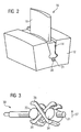
- a blade attachment 10 is shown by a turbine, not further illustrated, in which a blade root 14 is supported on a blade holder 12 on a rotor of the turbine.
- the blade root 14 is part of a blade 16, from which an airfoil 18 protrudes substantially radially from the shaft and thus perpendicularly from the blade root.
- the blade root 14 is designed with a fir tree-like profile 20 which is inserted into a curved groove 22 formed in the blade holder 12. At the bottom of the groove 22 is located between the inserted blade root 14 and the blade holder 12 a substantially over the entire length of the groove 22 extending recess 24 in the blade root 14, in which a securing device 30 is inserted.
- the securing device 30 comprises, as in FIG. 3
- the rotating means 31 can be moved in both rotational directions (clockwise or counterclockwise).
- the rotating means 31 further includes a first thread 32 and a second thread 33 counter-clockwise made to the first thread 32.
- On the first thread 32 a first displacement means 34 is arranged.
- the displacement means 34 has a bore into which the rotation means 31 projects.
- the displacement means 34 therefore comprises a complementary thread.
- a second displacement means 35 is arranged on the second thread 33, which, like the first displacement means 34 has a bore with a corresponding thread.
- the displacement means 34 and 35 are either moved toward or away from each other, depending on which rotational direction the rotation means 31 is moved in.
- a pressure medium designed as a pressure bar 36 is arranged between the first displacement means 34 and the second displacement means 35. Rotation of the rotating means 31 results in movement of the pressure means in a radial direction 37.
- the pressure bar 36 may be formed U-shaped, wherein the two legs can be arranged in each case left and right of the rotating means 31.
- a second pressure bar 38 which may also be U-shaped, is disposed between the first displacement means 34 and the second displacement means 35.
- the bucket 16 can be seen in the installed state.
- the securing device 30 is arranged in a groove 39, wherein of the securing device 30 substantially only the rotating means 31 can be seen.
- FIG. 4 a cross section through the blade 16 and the blade holder 12 is shown.
- the securing device 10 is mounted in a groove 39.
- the two pressure beams 38 and 36 are moved in the radial direction 37, whereby a force is exerted by the blade holder 12 on the blade root 14, thereby the turbine blade 16 is held firmly to the blade holder 12.
- FIG. 5 is an enlarged view of the securing device 30 of the FIG. 4 shown.
- the operation and assignment of the reference numerals applies accordingly.
- the pressure bars 36 and 38 may be disposed at their ends in retaining grooves 40 and 41. This prevents the safety device from slipping out of the groove 39.
- FIG. 6 is a perspective view of the securing device 30 can be seen.
- the rotating means 31 may be implemented as a square 44 at one end. As a result, tools can be easily arranged on the rotating means 31, so that a rotational movement can be transmitted to the rotating means 31.
- FIG. 7 is an alternative not belonging to the invention embodiment of the securing device 10 can be seen.
- the securing device 30 is executed so to speak as a jack.
- the securing device 30 has a first upper bar 50 and a second upper bar 51, which is connected at one end to the first displacement means 46 and the second upper bar 51 is connected to the second displacement means 48.
- the securing device 30 has a first lower rod 52 and a second lower rod 53.
- the first lower rod 52 is connected at one end to the first displacement means 46, whereas the second lower rod 53 is connected at one end to the second displacement means 48.
- the first upper rod 50 and the second upper rod 51 are connected at their other end together to a fitting key 54.
- the first lower rod 52 and the second lower rod 53 are connected at their end to a lower fitting wedge 55.
- a rotation of the rotating means 31 leads via the oppositely formed threads 32 and 33 to a movement of the displacement means 46 and 48 to each other or away from each other.
- the displacement means 46 and 48 are moved toward each other, the first upper rod 50 and the second upper rod 51 are moved in the radial direction, and the first lower rod 52 and the second lower rod 53 are moved in the radial direction 37.
- the pass wedges 54 and 55 will be Thus, on the one hand pressed against the blade root 14 and the other against the blade holder 12.
- the upper wedge 54 is located on the blade root 14 in a corresponding groove 56.
- the lower wedge 55 is applied to the blade holder in a corresponding groove 57 at. A displacement of the securing device 10 in the axial direction is thus effectively prevented.
- FIG. 8 is a perspective view of the securing device of the FIG. 7 to see.
- the same reference numerals have the same meaning and the effect described.
- the first upper bar 50, the second upper bar 51, the first lower bar 52, and the second lower bar 53 may be attached to the shifting means 46, shifting means 48, to the wedge 54, as well as to the lower fitting wedge 55, by conventional connecting means such as screws or rivets be attached.
Landscapes
- Engineering & Computer Science (AREA)
- Mechanical Engineering (AREA)
- General Engineering & Computer Science (AREA)
- Turbine Rotor Nozzle Sealing (AREA)
Claims (4)
- Dispositif ( 30 ) de fixation pour la fixation radiale d'une aube ( 16 ),
dans lequel il est prévu un moyen d'application d'une pression pour appliquer une force de pression à l'état monté sur une emplanture ( 14 ) de l'aube dans la direction ( 37 ) radiale, dans lequel il est prévu un moyen ( 31 ) de rotation et
le dispositif ( 30 ) de fixation est tel que par un mouvement de rotation du moyen ( 31 ) de rotation à l'aide d'un filetage ( 32, 33 ) la force de pression peut être appliquée, comprenant
deux moyens ( 34, 35 ) de déplacement mobiles l'un par rapport à l'autre,
caractérisé en ce que
le moyen d'application d'une pression comporte une poutre ( 36, 38 ) d'application d'une pression montée mobile,
dans lequel un moyen ( 34, 35 ) de déplacement est monté sur le moyen ( 31 ) de rotation,
de manière à ce qu'une rotation du moyen ( 31 ) de rotation provoque un déplacement du moyen ( 34, 35 ) de déplacement,
le déplacement du moyen ( 34, 35 ) de déplacement provoquant un mouvement de la poutre ( 36, 38 ) d'application d'un pression. - Dispositif ( 30 ) de fixation suivant la revendication 1, dans lequel le moyen ( 31 ) de rotation comporte un filetage ( 32, 33 ) et le moyen ( 34, 35 ) de déplacement comporte un filetage antagoniste.
- Dispositif ( 30 ) de fixation suivant la revendication 2, dans lequel la poutre ( 36, 38 ) d'application d'une pression est élastique.
- Dispositif ( 30 ) de fixation suivant l'une des revendications précédentes,
dans lequel le dispositif ( 30 ) de fixation est prévu pour le montage d'une rainure ( 39 ) dans une emplanture ( 14 ) d'aube et/ou dans un rotor.
Priority Applications (1)
| Application Number | Priority Date | Filing Date | Title |
|---|---|---|---|
| EP07820448A EP2066871B1 (fr) | 2006-09-27 | 2007-09-21 | Dispositif de fixation d'une aube de turbine |
Applications Claiming Priority (3)
| Application Number | Priority Date | Filing Date | Title |
|---|---|---|---|
| EP06020318A EP1905957A1 (fr) | 2006-09-27 | 2006-09-27 | Dispositif de fixation d'une aube de turbine |
| EP07820448A EP2066871B1 (fr) | 2006-09-27 | 2007-09-21 | Dispositif de fixation d'une aube de turbine |
| PCT/EP2007/060021 WO2008037661A1 (fr) | 2006-09-27 | 2007-09-21 | Dispositif de protection d'une aube de turbine |
Publications (2)
| Publication Number | Publication Date |
|---|---|
| EP2066871A1 EP2066871A1 (fr) | 2009-06-10 |
| EP2066871B1 true EP2066871B1 (fr) | 2011-10-26 |
Family
ID=37807898
Family Applications (2)
| Application Number | Title | Priority Date | Filing Date |
|---|---|---|---|
| EP06020318A Withdrawn EP1905957A1 (fr) | 2006-09-27 | 2006-09-27 | Dispositif de fixation d'une aube de turbine |
| EP07820448A Not-in-force EP2066871B1 (fr) | 2006-09-27 | 2007-09-21 | Dispositif de fixation d'une aube de turbine |
Family Applications Before (1)
| Application Number | Title | Priority Date | Filing Date |
|---|---|---|---|
| EP06020318A Withdrawn EP1905957A1 (fr) | 2006-09-27 | 2006-09-27 | Dispositif de fixation d'une aube de turbine |
Country Status (3)
| Country | Link |
|---|---|
| EP (2) | EP1905957A1 (fr) |
| AT (1) | ATE530734T1 (fr) |
| WO (1) | WO2008037661A1 (fr) |
Families Citing this family (6)
| Publication number | Priority date | Publication date | Assignee | Title |
|---|---|---|---|---|
| EP2090750A1 (fr) * | 2008-02-14 | 2009-08-19 | Siemens Aktiengesellschaft | Rotor de turbomachine, aube rotorique pour un tel rotor de turbomachine, languette de calage et procédé d'assemblage associé |
| ATE523659T1 (de) | 2008-07-30 | 2011-09-15 | Siemens Ag | Befestigungsanordnung zur befestigung von einer laufschaufel an einem rotor einer turbomaschine |
| EP2299060A1 (fr) | 2009-09-17 | 2011-03-23 | Siemens Aktiengesellschaft | Fixation des aubes avec dispositif de verrouillage pour aubes de turbines |
| GB201504182D0 (en) * | 2015-03-12 | 2015-04-29 | Rolls Royce Plc | Chocking and retaining device |
| FR3102206B1 (fr) * | 2019-10-18 | 2023-02-17 | Safran Aircraft Engines | Ensemble pour une aube de turbomachine comprenant une attache définissant une alvéole et une cale adaptée pour être reçue dans l’alvéole en même temps qu’un pied de l’aube |
| WO2022079360A1 (fr) * | 2020-10-16 | 2022-04-21 | Safran Aircraft Engines | Ensemble d'attache pour une aube de turbomachine |
Family Cites Families (7)
| Publication number | Priority date | Publication date | Assignee | Title |
|---|---|---|---|---|
| DE834408C (de) * | 1950-11-23 | 1952-03-20 | Maschf Augsburg Nuernberg Ag | Vorverspannte axiale Schaufelfussbefestigung fuer Dampf- und Gasturbinen |
| US2846183A (en) * | 1952-07-18 | 1958-08-05 | William C Morgan | Retaining devices for turbine blades |
| US3720481A (en) * | 1971-04-28 | 1973-03-13 | Avco Corp | Means for forming and securing turbine compressor blades |
| FR2323908A1 (fr) * | 1975-09-11 | 1977-04-08 | Alsthom Cgee | Dispositif de blocage d'une piece montee dans une rainure |
| JPS59192801A (ja) * | 1983-04-15 | 1984-11-01 | Hitachi Ltd | 着脱容易な動翼固定方法 |
| US5123813A (en) * | 1991-03-01 | 1992-06-23 | General Electric Company | Apparatus for preloading an airfoil blade in a gas turbine engine |
| EP1752611B1 (fr) * | 2005-08-12 | 2008-04-09 | Siemens Aktiengesellschaft | Turbine pour une centrale thermique avec dispositif de fixation |
-
2006
- 2006-09-27 EP EP06020318A patent/EP1905957A1/fr not_active Withdrawn
-
2007
- 2007-09-21 EP EP07820448A patent/EP2066871B1/fr not_active Not-in-force
- 2007-09-21 AT AT07820448T patent/ATE530734T1/de active
- 2007-09-21 WO PCT/EP2007/060021 patent/WO2008037661A1/fr active Application Filing
Also Published As
| Publication number | Publication date |
|---|---|
| EP1905957A1 (fr) | 2008-04-02 |
| WO2008037661A1 (fr) | 2008-04-03 |
| ATE530734T1 (de) | 2011-11-15 |
| EP2066871A1 (fr) | 2009-06-10 |
Similar Documents
| Publication | Publication Date | Title |
|---|---|---|
| EP2076656B1 (fr) | Fixation d'aube de turbine | |
| EP2399004B1 (fr) | Section de rotor pour un rotor d'une turbomachine, aube rotorique pour une turbomachine et élément de blocage | |
| EP2066871B1 (fr) | Dispositif de fixation d'une aube de turbine | |
| EP3212895B1 (fr) | Rotor comportant une aube de turbine avec un dispositif de verrouillage | |
| EP2478187B1 (fr) | Fixation des aubes avec dispositif de verrouillage pour aubes de turbines | |
| WO2007000326A1 (fr) | Rotor pour une turbine et procede et dispositif pour produire ce rotor | |
| CH698337B1 (de) | Anordnung mit einem Halterungssystem zur Halterung zweier Maschinenbauteile. | |
| DE102012023437A1 (de) | Rundlaufoptimiertes Werkzeugspannsystem für Dentalwinkelhandstücke und Dentalturbinen | |
| DE3320699A1 (de) | Vorrichtung zum veraendern des leitschaufelwinkels bei axialen stroemungsmaschinen | |
| EP2149677B1 (fr) | Dispositif de fixation destiné à la fixation d'une pale de rotor sur une turbomachine | |
| EP1643082A1 (fr) | Fixation d'aubes de turbine | |
| EP2682624B1 (fr) | Accouplement à friction avec compensation d'usure en fonction de la course | |
| EP3164604A1 (fr) | Dispositif de fixation et procédé pour fixer une roue à aubes d'un compresseur sur un arbre d'entrée | |
| EP3035503B1 (fr) | Machine dynamoélectrique dotée d'un frein | |
| DE60016048T2 (de) | Laufrad für axialventilator und schaufel-nabe verbindungsverfahren für einen solchen ventilator | |
| EP3230559B1 (fr) | Module final pour verrouiller une roue aubagée, organe de support d'aube, turbomachine et procédé d'insertion de module final associés | |
| EP3172409B1 (fr) | Agencement de disque de roue pourvu de tôles d'étanchéité | |
| EP2399005A1 (fr) | Groupe d'aubes d'une turbomachine | |
| EP1350924B1 (fr) | Attachement des éléments de stator dans une turbine à gaz | |
| CH624188A5 (en) | Device for securing a profiled shaft | |
| EP1707747A1 (fr) | Système de fixation des pieds d'aubes et procédé de montage correspondant | |
| DE10322728B3 (de) | Befestigungseinrichtung | |
| DE102019218196A1 (de) | Elektromotorisch angetriebenes Aggregat für ein Fahrzeug | |
| EP2246575A1 (fr) | Agencement d'aube mobile pour un compresseur axial | |
| DE3500975A1 (de) | Verbindungseinrichtung fuer zwei gehaeuseteile eines selbstschalters |
Legal Events
| Date | Code | Title | Description |
|---|---|---|---|
| PUAI | Public reference made under article 153(3) epc to a published international application that has entered the european phase |
Free format text: ORIGINAL CODE: 0009012 |
|
| 17P | Request for examination filed |
Effective date: 20090227 |
|
| AK | Designated contracting states |
Kind code of ref document: A1 Designated state(s): AT BE BG CH CY CZ DE DK EE ES FI FR GB GR HU IE IS IT LI LT LU LV MC MT NL PL PT RO SE SI SK TR |
|
| AX | Request for extension of the european patent |
Extension state: AL BA HR MK RS |
|
| 17Q | First examination report despatched |
Effective date: 20091012 |
|
| GRAP | Despatch of communication of intention to grant a patent |
Free format text: ORIGINAL CODE: EPIDOSNIGR1 |
|
| GRAS | Grant fee paid |
Free format text: ORIGINAL CODE: EPIDOSNIGR3 |
|
| GRAA | (expected) grant |
Free format text: ORIGINAL CODE: 0009210 |
|
| AK | Designated contracting states |
Kind code of ref document: B1 Designated state(s): AT BE BG CH CY CZ DE DK EE ES FI FR GB GR HU IE IS IT LI LT LU LV MC MT NL PL PT RO SE SI SK TR |
|
| DAX | Request for extension of the european patent (deleted) | ||
| REG | Reference to a national code |
Ref country code: GB Ref legal event code: FG4D Free format text: NOT ENGLISH |
|
| REG | Reference to a national code |
Ref country code: CH Ref legal event code: EP |
|
| REG | Reference to a national code |
Ref country code: IE Ref legal event code: FG4D |
|
| REG | Reference to a national code |
Ref country code: CH Ref legal event code: NV Representative=s name: SIEMENS SCHWEIZ AG |
|
| REG | Reference to a national code |
Ref country code: DE Ref legal event code: R096 Ref document number: 502007008554 Country of ref document: DE Effective date: 20111222 |
|
| REG | Reference to a national code |
Ref country code: NL Ref legal event code: VDEP Effective date: 20111026 |
|
| LTIE | Lt: invalidation of european patent or patent extension |
Effective date: 20111026 |
|
| PG25 | Lapsed in a contracting state [announced via postgrant information from national office to epo] |
Ref country code: IS Free format text: LAPSE BECAUSE OF FAILURE TO SUBMIT A TRANSLATION OF THE DESCRIPTION OR TO PAY THE FEE WITHIN THE PRESCRIBED TIME-LIMIT Effective date: 20120226 Ref country code: LT Free format text: LAPSE BECAUSE OF FAILURE TO SUBMIT A TRANSLATION OF THE DESCRIPTION OR TO PAY THE FEE WITHIN THE PRESCRIBED TIME-LIMIT Effective date: 20111026 |
|
| PG25 | Lapsed in a contracting state [announced via postgrant information from national office to epo] |
Ref country code: PT Free format text: LAPSE BECAUSE OF FAILURE TO SUBMIT A TRANSLATION OF THE DESCRIPTION OR TO PAY THE FEE WITHIN THE PRESCRIBED TIME-LIMIT Effective date: 20120227 Ref country code: NL Free format text: LAPSE BECAUSE OF FAILURE TO SUBMIT A TRANSLATION OF THE DESCRIPTION OR TO PAY THE FEE WITHIN THE PRESCRIBED TIME-LIMIT Effective date: 20111026 Ref country code: PL Free format text: LAPSE BECAUSE OF FAILURE TO SUBMIT A TRANSLATION OF THE DESCRIPTION OR TO PAY THE FEE WITHIN THE PRESCRIBED TIME-LIMIT Effective date: 20111026 Ref country code: SE Free format text: LAPSE BECAUSE OF FAILURE TO SUBMIT A TRANSLATION OF THE DESCRIPTION OR TO PAY THE FEE WITHIN THE PRESCRIBED TIME-LIMIT Effective date: 20111026 Ref country code: LV Free format text: LAPSE BECAUSE OF FAILURE TO SUBMIT A TRANSLATION OF THE DESCRIPTION OR TO PAY THE FEE WITHIN THE PRESCRIBED TIME-LIMIT Effective date: 20111026 Ref country code: SI Free format text: LAPSE BECAUSE OF FAILURE TO SUBMIT A TRANSLATION OF THE DESCRIPTION OR TO PAY THE FEE WITHIN THE PRESCRIBED TIME-LIMIT Effective date: 20111026 Ref country code: GR Free format text: LAPSE BECAUSE OF FAILURE TO SUBMIT A TRANSLATION OF THE DESCRIPTION OR TO PAY THE FEE WITHIN THE PRESCRIBED TIME-LIMIT Effective date: 20120127 |
|
| REG | Reference to a national code |
Ref country code: IE Ref legal event code: FD4D |
|
| PG25 | Lapsed in a contracting state [announced via postgrant information from national office to epo] |
Ref country code: CY Free format text: LAPSE BECAUSE OF FAILURE TO SUBMIT A TRANSLATION OF THE DESCRIPTION OR TO PAY THE FEE WITHIN THE PRESCRIBED TIME-LIMIT Effective date: 20111026 |
|
| PG25 | Lapsed in a contracting state [announced via postgrant information from national office to epo] |
Ref country code: EE Free format text: LAPSE BECAUSE OF FAILURE TO SUBMIT A TRANSLATION OF THE DESCRIPTION OR TO PAY THE FEE WITHIN THE PRESCRIBED TIME-LIMIT Effective date: 20111026 Ref country code: CZ Free format text: LAPSE BECAUSE OF FAILURE TO SUBMIT A TRANSLATION OF THE DESCRIPTION OR TO PAY THE FEE WITHIN THE PRESCRIBED TIME-LIMIT Effective date: 20111026 Ref country code: BG Free format text: LAPSE BECAUSE OF FAILURE TO SUBMIT A TRANSLATION OF THE DESCRIPTION OR TO PAY THE FEE WITHIN THE PRESCRIBED TIME-LIMIT Effective date: 20120126 Ref country code: IE Free format text: LAPSE BECAUSE OF FAILURE TO SUBMIT A TRANSLATION OF THE DESCRIPTION OR TO PAY THE FEE WITHIN THE PRESCRIBED TIME-LIMIT Effective date: 20111026 Ref country code: DK Free format text: LAPSE BECAUSE OF FAILURE TO SUBMIT A TRANSLATION OF THE DESCRIPTION OR TO PAY THE FEE WITHIN THE PRESCRIBED TIME-LIMIT Effective date: 20111026 Ref country code: SK Free format text: LAPSE BECAUSE OF FAILURE TO SUBMIT A TRANSLATION OF THE DESCRIPTION OR TO PAY THE FEE WITHIN THE PRESCRIBED TIME-LIMIT Effective date: 20111026 |
|
| PG25 | Lapsed in a contracting state [announced via postgrant information from national office to epo] |
Ref country code: RO Free format text: LAPSE BECAUSE OF FAILURE TO SUBMIT A TRANSLATION OF THE DESCRIPTION OR TO PAY THE FEE WITHIN THE PRESCRIBED TIME-LIMIT Effective date: 20111026 |
|
| PLBE | No opposition filed within time limit |
Free format text: ORIGINAL CODE: 0009261 |
|
| STAA | Information on the status of an ep patent application or granted ep patent |
Free format text: STATUS: NO OPPOSITION FILED WITHIN TIME LIMIT |
|
| 26N | No opposition filed |
Effective date: 20120727 |
|
| REG | Reference to a national code |
Ref country code: DE Ref legal event code: R097 Ref document number: 502007008554 Country of ref document: DE Effective date: 20120727 |
|
| BERE | Be: lapsed |
Owner name: SIEMENS A.G. Effective date: 20120930 |
|
| PG25 | Lapsed in a contracting state [announced via postgrant information from national office to epo] |
Ref country code: ES Free format text: LAPSE BECAUSE OF FAILURE TO SUBMIT A TRANSLATION OF THE DESCRIPTION OR TO PAY THE FEE WITHIN THE PRESCRIBED TIME-LIMIT Effective date: 20120206 Ref country code: MC Free format text: LAPSE BECAUSE OF NON-PAYMENT OF DUE FEES Effective date: 20120930 |
|
| PG25 | Lapsed in a contracting state [announced via postgrant information from national office to epo] |
Ref country code: FI Free format text: LAPSE BECAUSE OF FAILURE TO SUBMIT A TRANSLATION OF THE DESCRIPTION OR TO PAY THE FEE WITHIN THE PRESCRIBED TIME-LIMIT Effective date: 20111026 |
|
| PG25 | Lapsed in a contracting state [announced via postgrant information from national office to epo] |
Ref country code: BE Free format text: LAPSE BECAUSE OF NON-PAYMENT OF DUE FEES Effective date: 20120930 |
|
| REG | Reference to a national code |
Ref country code: AT Ref legal event code: MM01 Ref document number: 530734 Country of ref document: AT Kind code of ref document: T Effective date: 20120921 |
|
| PG25 | Lapsed in a contracting state [announced via postgrant information from national office to epo] |
Ref country code: MT Free format text: LAPSE BECAUSE OF FAILURE TO SUBMIT A TRANSLATION OF THE DESCRIPTION OR TO PAY THE FEE WITHIN THE PRESCRIBED TIME-LIMIT Effective date: 20111026 |
|
| PG25 | Lapsed in a contracting state [announced via postgrant information from national office to epo] |
Ref country code: AT Free format text: LAPSE BECAUSE OF NON-PAYMENT OF DUE FEES Effective date: 20120921 |
|
| PG25 | Lapsed in a contracting state [announced via postgrant information from national office to epo] |
Ref country code: TR Free format text: LAPSE BECAUSE OF FAILURE TO SUBMIT A TRANSLATION OF THE DESCRIPTION OR TO PAY THE FEE WITHIN THE PRESCRIBED TIME-LIMIT Effective date: 20111026 |
|
| PG25 | Lapsed in a contracting state [announced via postgrant information from national office to epo] |
Ref country code: LU Free format text: LAPSE BECAUSE OF NON-PAYMENT OF DUE FEES Effective date: 20120921 |
|
| PG25 | Lapsed in a contracting state [announced via postgrant information from national office to epo] |
Ref country code: HU Free format text: LAPSE BECAUSE OF FAILURE TO SUBMIT A TRANSLATION OF THE DESCRIPTION OR TO PAY THE FEE WITHIN THE PRESCRIBED TIME-LIMIT Effective date: 20070921 |
|
| REG | Reference to a national code |
Ref country code: FR Ref legal event code: PLFP Year of fee payment: 9 |
|
| PGFP | Annual fee paid to national office [announced via postgrant information from national office to epo] |
Ref country code: GB Payment date: 20150909 Year of fee payment: 9 |
|
| PGFP | Annual fee paid to national office [announced via postgrant information from national office to epo] |
Ref country code: FR Payment date: 20150910 Year of fee payment: 9 |
|
| PGFP | Annual fee paid to national office [announced via postgrant information from national office to epo] |
Ref country code: IT Payment date: 20150924 Year of fee payment: 9 |
|
| PGFP | Annual fee paid to national office [announced via postgrant information from national office to epo] |
Ref country code: DE Payment date: 20151120 Year of fee payment: 9 Ref country code: CH Payment date: 20151202 Year of fee payment: 9 |
|
| REG | Reference to a national code |
Ref country code: DE Ref legal event code: R119 Ref document number: 502007008554 Country of ref document: DE |
|
| REG | Reference to a national code |
Ref country code: CH Ref legal event code: PL |
|
| GBPC | Gb: european patent ceased through non-payment of renewal fee |
Effective date: 20160921 |
|
| REG | Reference to a national code |
Ref country code: FR Ref legal event code: ST Effective date: 20170531 |
|
| PG25 | Lapsed in a contracting state [announced via postgrant information from national office to epo] |
Ref country code: CH Free format text: LAPSE BECAUSE OF NON-PAYMENT OF DUE FEES Effective date: 20160930 Ref country code: GB Free format text: LAPSE BECAUSE OF NON-PAYMENT OF DUE FEES Effective date: 20160921 Ref country code: LI Free format text: LAPSE BECAUSE OF NON-PAYMENT OF DUE FEES Effective date: 20160930 Ref country code: FR Free format text: LAPSE BECAUSE OF NON-PAYMENT OF DUE FEES Effective date: 20160930 Ref country code: DE Free format text: LAPSE BECAUSE OF NON-PAYMENT OF DUE FEES Effective date: 20170401 |
|
| PG25 | Lapsed in a contracting state [announced via postgrant information from national office to epo] |
Ref country code: IT Free format text: LAPSE BECAUSE OF NON-PAYMENT OF DUE FEES Effective date: 20160921 |