EP2066871B1 - Securing apparatus of a turbine blade - Google Patents
Securing apparatus of a turbine blade Download PDFInfo
- Publication number
- EP2066871B1 EP2066871B1 EP07820448A EP07820448A EP2066871B1 EP 2066871 B1 EP2066871 B1 EP 2066871B1 EP 07820448 A EP07820448 A EP 07820448A EP 07820448 A EP07820448 A EP 07820448A EP 2066871 B1 EP2066871 B1 EP 2066871B1
- Authority
- EP
- European Patent Office
- Prior art keywords
- securing device
- pressure
- blade
- blade root
- displacement
- Prior art date
- Legal status (The legal status is an assumption and is not a legal conclusion. Google has not performed a legal analysis and makes no representation as to the accuracy of the status listed.)
- Not-in-force
Links
Images


Classifications
-
- F—MECHANICAL ENGINEERING; LIGHTING; HEATING; WEAPONS; BLASTING
- F01—MACHINES OR ENGINES IN GENERAL; ENGINE PLANTS IN GENERAL; STEAM ENGINES
- F01D—NON-POSITIVE DISPLACEMENT MACHINES OR ENGINES, e.g. STEAM TURBINES
- F01D5/00—Blades; Blade-carrying members; Heating, heat-insulating, cooling or antivibration means on the blades or the members
- F01D5/30—Fixing blades to rotors; Blade roots ; Blade spacers
- F01D5/32—Locking, e.g. by final locking blades or keys
- F01D5/323—Locking of axial insertion type blades by means of a key or the like parallel to the axis of the rotor
-
- F—MECHANICAL ENGINEERING; LIGHTING; HEATING; WEAPONS; BLASTING
- F05—INDEXING SCHEMES RELATING TO ENGINES OR PUMPS IN VARIOUS SUBCLASSES OF CLASSES F01-F04
- F05D—INDEXING SCHEME FOR ASPECTS RELATING TO NON-POSITIVE-DISPLACEMENT MACHINES OR ENGINES, GAS-TURBINES OR JET-PROPULSION PLANTS
- F05D2250/00—Geometry
- F05D2250/20—Three-dimensional
- F05D2250/28—Three-dimensional patterned
- F05D2250/281—Three-dimensional patterned threaded
-
- F—MECHANICAL ENGINEERING; LIGHTING; HEATING; WEAPONS; BLASTING
- F05—INDEXING SCHEMES RELATING TO ENGINES OR PUMPS IN VARIOUS SUBCLASSES OF CLASSES F01-F04
- F05D—INDEXING SCHEME FOR ASPECTS RELATING TO NON-POSITIVE-DISPLACEMENT MACHINES OR ENGINES, GAS-TURBINES OR JET-PROPULSION PLANTS
- F05D2260/00—Function
- F05D2260/30—Retaining components in desired mutual position
Definitions
- the invention relates to a securing device for the radial securing of a turbine blade, wherein a pressure means for exerting a compressive force on a turbine blade root is provided in the radial direction.
- Blade fasteners of the above type are typically used to secure blades to a rotor of a turbine which revolve at high speed as the rotor rotates. Due to the fast rotation of the rotor, the associated blades are subjected to high centrifugal force. The blade root of the blades is therefore exposed to high forces and is strongly forced radially outward in the groove on the blade holder. In addition, the blades are exposed to strong vibration loads, so that it can come to the groove to mechanical damage, material fatigue, corrosion and migration of the blade root within the groove. For fixing the blade root within the groove, various solutions such as metal wedges, spring washers or sealing pieces are known.
- the FR 2 323 908 discloses a blade guard with a wedge-shaped pressure means.
- JP 59 192801 discloses a movable over a screw blade guard.
- the US 2,846,183 discloses a blade armature acting by means of spring forces.
- the US 3,720,481 discloses a safety device for radial securing of a blade according to the preamble of claim 1.
- the invention has for its object to provide a blade mounting a turbine in which over a long period of operation, a precise and low-vibration mounting of blades is ensured in associated blade holders.
- a securing device for radial securing of a turbine blade wherein a pressure means for exerting a compressive force on a turbine blade root in the radial direction and a rotating means is provided and the securing device is designed such that by a rotational movement of the rotating means the pressure force is exercisable.
- two displacement means which are designed to be movable relative to one another. Since, as already mentioned, a high force can be transmitted via a rotary movement, it is advantageous if two displacement means can be provided, which can be formed by the rotational movement to each other. As a result, the transferable pressure force on the turbine blade root in the radial direction increases even further.
- the securing device is first inserted into a groove.
- the rotating means is set in a rotational movement. Due to the rotational movement of the rotating means, the pressure medium is enabled to exert a compressive force.
- the compressive force finally achieves the effect that the turbine blade in radial Direction is being moved. As the blade root is inserted into blade holders, counter forces occur. The combination of compressive force and counterforce causes the turbine blade to be effectively held in the blade holder.
- Another advantage of the invention is that by a rotational movement of the rotating means, which points in an opposite direction, the pressure force can be reduced again and thus the securing device can be released from the turbine blade, resulting in a non-destructive expansion of the securing device.
- the pressure medium has a movably arranged pressure bar. This makes it possible to design the securing device by a structurally simple construction.
- a displacement means is arranged on the rotation means such that a rotation of the rotation means leads to a displacement of the displacement means.
- This is a simple variant for moving a displacement means, which eventually leads to a movement of the pressure beam. Since very high forces can be transmitted via rotational movements, a very high force can be transmitted to the pressure medium via the displacement means and the rotation means, which in turn leads to a high pressure Compressive force on the turbine blade root in the radial direction leads.
- the pressure bar is designed to be elastic. This makes it possible for a pressure force to be exerted on the turbine blade root in the radial direction during operation. In general, a high centrifugal force acts on the turbine blade root in the radial direction during operation. This means that a rigidly set pressure force on the turbine blade root would be lower. By a resilient pressure beam, the pressure force on the turbine blade root is maintained over a certain distance, although the turbine blade root moves away from the pressure beam.
- the securing device is provided for installation in a groove in a blade root and / or in a rotor.
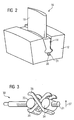
- a blade attachment 10 is shown by a turbine, not further illustrated, in which a blade root 14 is supported on a blade holder 12 on a rotor of the turbine.
- the blade root 14 is part of a blade 16, from which an airfoil 18 protrudes substantially radially from the shaft and thus perpendicularly from the blade root.
- the blade root 14 is designed with a fir tree-like profile 20 which is inserted into a curved groove 22 formed in the blade holder 12. At the bottom of the groove 22 is located between the inserted blade root 14 and the blade holder 12 a substantially over the entire length of the groove 22 extending recess 24 in the blade root 14, in which a securing device 30 is inserted.
- the securing device 30 comprises, as in FIG. 3
- the rotating means 31 can be moved in both rotational directions (clockwise or counterclockwise).
- the rotating means 31 further includes a first thread 32 and a second thread 33 counter-clockwise made to the first thread 32.
- On the first thread 32 a first displacement means 34 is arranged.
- the displacement means 34 has a bore into which the rotation means 31 projects.
- the displacement means 34 therefore comprises a complementary thread.
- a second displacement means 35 is arranged on the second thread 33, which, like the first displacement means 34 has a bore with a corresponding thread.
- the displacement means 34 and 35 are either moved toward or away from each other, depending on which rotational direction the rotation means 31 is moved in.
- a pressure medium designed as a pressure bar 36 is arranged between the first displacement means 34 and the second displacement means 35. Rotation of the rotating means 31 results in movement of the pressure means in a radial direction 37.
- the pressure bar 36 may be formed U-shaped, wherein the two legs can be arranged in each case left and right of the rotating means 31.
- a second pressure bar 38 which may also be U-shaped, is disposed between the first displacement means 34 and the second displacement means 35.
- the bucket 16 can be seen in the installed state.
- the securing device 30 is arranged in a groove 39, wherein of the securing device 30 substantially only the rotating means 31 can be seen.
- FIG. 4 a cross section through the blade 16 and the blade holder 12 is shown.
- the securing device 10 is mounted in a groove 39.
- the two pressure beams 38 and 36 are moved in the radial direction 37, whereby a force is exerted by the blade holder 12 on the blade root 14, thereby the turbine blade 16 is held firmly to the blade holder 12.
- FIG. 5 is an enlarged view of the securing device 30 of the FIG. 4 shown.
- the operation and assignment of the reference numerals applies accordingly.
- the pressure bars 36 and 38 may be disposed at their ends in retaining grooves 40 and 41. This prevents the safety device from slipping out of the groove 39.
- FIG. 6 is a perspective view of the securing device 30 can be seen.
- the rotating means 31 may be implemented as a square 44 at one end. As a result, tools can be easily arranged on the rotating means 31, so that a rotational movement can be transmitted to the rotating means 31.
- FIG. 7 is an alternative not belonging to the invention embodiment of the securing device 10 can be seen.
- the securing device 30 is executed so to speak as a jack.
- the securing device 30 has a first upper bar 50 and a second upper bar 51, which is connected at one end to the first displacement means 46 and the second upper bar 51 is connected to the second displacement means 48.
- the securing device 30 has a first lower rod 52 and a second lower rod 53.
- the first lower rod 52 is connected at one end to the first displacement means 46, whereas the second lower rod 53 is connected at one end to the second displacement means 48.
- the first upper rod 50 and the second upper rod 51 are connected at their other end together to a fitting key 54.
- the first lower rod 52 and the second lower rod 53 are connected at their end to a lower fitting wedge 55.
- a rotation of the rotating means 31 leads via the oppositely formed threads 32 and 33 to a movement of the displacement means 46 and 48 to each other or away from each other.
- the displacement means 46 and 48 are moved toward each other, the first upper rod 50 and the second upper rod 51 are moved in the radial direction, and the first lower rod 52 and the second lower rod 53 are moved in the radial direction 37.
- the pass wedges 54 and 55 will be Thus, on the one hand pressed against the blade root 14 and the other against the blade holder 12.
- the upper wedge 54 is located on the blade root 14 in a corresponding groove 56.
- the lower wedge 55 is applied to the blade holder in a corresponding groove 57 at. A displacement of the securing device 10 in the axial direction is thus effectively prevented.
- FIG. 8 is a perspective view of the securing device of the FIG. 7 to see.
- the same reference numerals have the same meaning and the effect described.
- the first upper bar 50, the second upper bar 51, the first lower bar 52, and the second lower bar 53 may be attached to the shifting means 46, shifting means 48, to the wedge 54, as well as to the lower fitting wedge 55, by conventional connecting means such as screws or rivets be attached.
Abstract
Description
Die Erfindung betrifft eine Sicherungsvorrichtung zur radialen Sicherung einer Turbinenschäufel, wobei ein Druckmittel zum Ausüben einer Druckkraft auf einen Turbinenschaufelfuß in radialer Richtung vorgesehen ist.The invention relates to a securing device for the radial securing of a turbine blade, wherein a pressure means for exerting a compressive force on a turbine blade root is provided in the radial direction.
Schaufelbefestigungen der oben genannten Art werden in der Regel zum Befestigen von Laufschaufeln an einem Rotor einer Turbine verwendet, die bei Rotation des Rotors mit hoher Geschwindigkeit umlaufen. Durch die schnelle Rotation des Rotors werden die zugehörigen Laufschaufeln einer hohen Fliehkraft unterworfen. Der Schaufelfuß der Schaufeln ist daher hohen Kräften ausgesetzt und wird in der Nut am Schaufelhalter stark radial nach außen gedrängt. Darüber hinaus sind die Schaufeln starken Schwingungsbelastungen ausgesetzt, so dass es an der Nut zu mechanischen Beschädigungen, Materialermüdungen, Korrosion und einer Wanderbewegung des Schaufelfußes innerhalb der Nut kommen kann. Zum Festlegen des Schaufelfußes innerhalb der Nut sind verschiedene Lösungen wie beispielsweise Metallkeile, Federringe oder Abdichtungsstücke bekannt. Metallkeile stellen zwar sowohl axial als auch radial eine Arretierung des zugehörigen Schaufelfußes innerhalb einer Nut her, bei großen Schaufeln ist es mit solchen Metallkeilen aber schwierig, dass während der Rotation der Schaufel ausreichend Haltekräfte in radialer Richtung erzeugt werden. Tellerfedern erzeugen lediglich radiale Haltekräfte und erfordern zusätzlichen Aufwand für eine Arretierung in Längsrichtung der zugehörigen Nut. Ferner sind für Tellerfedern während der Montage aufwendige Messungen erforderlich. Als Abdichtungsstücke müssen immer zwei Teile vorgesehen sein, deren Montage darüber hinaus teilweise die Bearbeitung der Teile von Hand bedarf.Blade fasteners of the above type are typically used to secure blades to a rotor of a turbine which revolve at high speed as the rotor rotates. Due to the fast rotation of the rotor, the associated blades are subjected to high centrifugal force. The blade root of the blades is therefore exposed to high forces and is strongly forced radially outward in the groove on the blade holder. In addition, the blades are exposed to strong vibration loads, so that it can come to the groove to mechanical damage, material fatigue, corrosion and migration of the blade root within the groove. For fixing the blade root within the groove, various solutions such as metal wedges, spring washers or sealing pieces are known. Although metal wedges produce locking of the associated blade root within a groove both axially and radially, with large blades it is difficult with such metal wedges that sufficient holding forces are generated in the radial direction during the rotation of the blade. Disc springs only generate radial holding forces and require additional effort for a locking in the longitudinal direction of the associated groove. Furthermore, complex measurements are required for disc springs during assembly. As a piece of sealing always two parts must be provided, the assembly beyond partially requires the processing of the parts by hand.
Die
In der
Die
Die
Der Erfindung liegt die Aufgabe zugrunde, eine Schaufelbefestigung einer Turbine bereitzustellen, bei der über einen lange Betriebszeitraum hinweg eine präzise und schwingungsarme Halterung von Schaufeln in zugehörigen Schaufelhaltern sichergestellt ist.The invention has for its object to provide a blade mounting a turbine in which over a long period of operation, a precise and low-vibration mounting of blades is ensured in associated blade holders.
Die Aufgabe wird gelöst durch die kennzeichnenden Merkmale des Anspruchs 1, indem eine Sicherungsvorrichtung zur radialen Sicherung einer Turbinenschaufel wird, wobei ein Druckmittel zum Ausüben einer Druckkraft auf einen Turbinenschaufelfuß in radialer Richtung und ein Drehmittel vorgesehen ist und die Sicherungsvorrichtung derart ausgebildet ist, dass durch eine rotatorische Bewegung des Drehmittels die Druckkraft ausübbar ist.The object is solved by the characterizing features of claim 1, by a securing device for radial securing of a turbine blade, wherein a pressure means for exerting a compressive force on a turbine blade root in the radial direction and a rotating means is provided and the securing device is designed such that by a rotational movement of the rotating means the pressure force is exercisable.
Es sind zwei Verschiebemittel vorgesehen, die zueinander bewegbar ausgebildet sind, vorgesehen. Da wie bereits erwähnt, über eine Drehbewegung eine hohe Kraft übertragen werden kann, ist es von Vorteil, wenn zwei Verschiebemittel vorgesehen werden können, die durch die Drehbewegung zueinander ausgebildet werden können. Dadurch erhöht sich die übertragbare Druckkraft auf den Turbinenschaufelfuß in radialer Richtung noch weiter.There are provided two displacement means which are designed to be movable relative to one another. Since, as already mentioned, a high force can be transmitted via a rotary movement, it is advantageous if two displacement means can be provided, which can be formed by the rotational movement to each other. As a result, the transferable pressure force on the turbine blade root in the radial direction increases even further.
Die Sicherungsvorrichtung wird zunächst in eine Nut eingeführt. In einem nächsten Schritt wird das Drehmittel in eine rotatorische Bewegung versetzt. Durch die rotatorische Bewegung des Drehmittels wird das Druckmittel in die Lage versetzt, eine Druckkraft auszuüben. Die Druckkraft schließlich erzielt die Wirkung, dass die Turbinenschaufel in radialer Richtung bewegt wird. Da der Schaufelfuß in Schaufelhaltern eingefügt wird, entstehen Gegenkräfte. Die Kombination aus Druckkraft und Gegenkraft bewirkt, dass die Turbinenschaufel wirksam im Schaufelhalter gehalten wird.The securing device is first inserted into a groove. In a next step, the rotating means is set in a rotational movement. Due to the rotational movement of the rotating means, the pressure medium is enabled to exert a compressive force. The compressive force finally achieves the effect that the turbine blade in radial Direction is being moved. As the blade root is inserted into blade holders, counter forces occur. The combination of compressive force and counterforce causes the turbine blade to be effectively held in the blade holder.
Erfindungsgemäß wird vorgeschlagen, die Druckkraft von außen durch eine rotatorische Bewegung des Drehmittels zu erzeugen. Dies ist ein bedeutender konstruktiver Vorteil, denn nun ist es möglich, eine Sicherungsvorrichtung ohne größere Widerstände in eine Nut einzufügen. Die Sicherungsvorrichtung kann dadurch exakt an vorgesehene Stellen bewegt werden. Die Druckkraft kann anschließend zwanglos durch eine rotatorische Drehbewegung des Drehmittels erzeugt werden.According to the invention it is proposed to generate the pressure force from the outside by a rotational movement of the rotating means. This is a significant design advantage, because now it is possible to insert a securing device without major resistance in a groove. The securing device can thereby be moved exactly to the intended places. The pressure force can then be generated easily by a rotary rotational movement of the rotating means.
Ein weiterer Vorteil der Erfindung ist es, dass durch eine rotatorische Bewegung des Drehmittels, die in eine Gegenrichtung zeigt, die Druckkraft wieder abgebaut werden kann und somit die Sicherungsvorrichtung von der Turbinenschaufel gelöst werden kann, was zu einem zerstörungsfreien Ausbau der Sicherungsvorrichtung führt.Another advantage of the invention is that by a rotational movement of the rotating means, which points in an opposite direction, the pressure force can be reduced again and thus the securing device can be released from the turbine blade, resulting in a non-destructive expansion of the securing device.
Vorteilhafte Weiterbildungen sind in den Unteransprüchen angegeben.Advantageous developments are specified in the subclaims.
Es ist erfindungswesentlich, dass das Druckmittel einen bewegbar angeordneten Druckbalken aufweiset. Dadurch ist es möglich, durch einen konstruktiv einfachen Aufbau die Sicherungsvorrichtung zu gestalten.It is essential to the invention that the pressure medium has a movably arranged pressure bar. This makes it possible to design the securing device by a structurally simple construction.
Des weiteren ist an dem Drehmittel ein Verschiebemittel derart angeordnet, dass eine Rotation des Drehmittels zu einer Verschiebung des Verschiebemittels führt. Dies ist eine einfache Variante, um ein Verschiebemittel zu bewegen, was schließlich zu einer Bewegung des Druckbalkens führt. Da über rotatorische Bewegungen sehr hohe Kräfte übertragen werden können, kann über das Verschiebemittel und das Drehmittel eine sehr hohe Kraft auf das Druckmittel übertragen werden, was wiederum zu einer hohen Druckkraft auf den Turbinenschaufelfuß in radialer Richtung führt.Furthermore, a displacement means is arranged on the rotation means such that a rotation of the rotation means leads to a displacement of the displacement means. This is a simple variant for moving a displacement means, which eventually leads to a movement of the pressure beam. Since very high forces can be transmitted via rotational movements, a very high force can be transmitted to the pressure medium via the displacement means and the rotation means, which in turn leads to a high pressure Compressive force on the turbine blade root in the radial direction leads.
In einer vorteilhaften Weiterbildung ist der Druckbalken elastisch ausgeführt. Dadurch ist es möglich, dass eine Druckkraft auf den Turbinenschaufelfuß in radialer Richtung aus im Betrieb ausgeübt wird. In der Regel wirkt im Betrieb eine hohe Zentrifugalkraft auf den Turbinenschaufelfuß in radialer Richtung. Das bedeutet, dass eine starr eingestellte Druckkraft auf den Turbinenschaufelfuß geringer würde. Durch einen elastischen Druckbalken bleibt die Druckkraft auf den Turbinenschaufelfuß über einen gewissen Weg erhalten, obwohl der Turbinenschaufelfuß sich weg von dem Druckbalken bewegt.In an advantageous development of the pressure bar is designed to be elastic. This makes it possible for a pressure force to be exerted on the turbine blade root in the radial direction during operation. In general, a high centrifugal force acts on the turbine blade root in the radial direction during operation. This means that a rigidly set pressure force on the turbine blade root would be lower. By a resilient pressure beam, the pressure force on the turbine blade root is maintained over a certain distance, although the turbine blade root moves away from the pressure beam.
In einer weiteren vorteilhaften Weiterbildung ist die Sicherungsvorrichtung zum Einbau in einer Nut in einem Schaufelfuß und/oder in einem Rotor vorgesehen.In a further advantageous development, the securing device is provided for installation in a groove in a blade root and / or in a rotor.
Nachfolgend wird ein Ausführungsbeispiel einer erfindungsgemäßen Schaufelbefestigung anhand der beigefügten schematischen Zeichnungen näher erläutert. Es zeigen:
- FIG 1
- eine teilweise aufgebrochene perspektivische Ansicht eines ersten Ausführungsbeispiels einer erfindungsgemäßen Schaufelbefestigung,
- FIG 2
- eine perspektivische Darstellung eines Turbinenschaufelfuß mit der Sicherungsvorrichtung,
- FIG 3
- eine perspektivische Darstellung der Sicherungsvorrichtung,
- FIG 4
- eine Querschnittsansicht eines Turbinenschaufelfußes mit der Sicherungsvorrichtung,
- FIG 5
- eine vergrößerte Darstellung der Sicherungsvorrichtung aus
FIG 4 , - FIG 6
- eine perspektivische Darstellung der Sicherungsvorrichtung,
- FIG 7
- eine Querschnittsansicht einer nicht zur Erfindung gehörenden alternativen Ausführungsform einer Sicherungsvorrichtung,
- FIG 8
- eine perspektivische Darstellung der alternativen Ausführungsform der Sicherungsvorrichtung.
- FIG. 1
- a partially broken perspective view of a first embodiment of a blade attachment according to the invention,
- FIG. 2
- a perspective view of a turbine blade root with the safety device,
- FIG. 3
- a perspective view of the securing device,
- FIG. 4
- a cross-sectional view of a turbine blade root with the safety device,
- FIG. 5
- an enlarged view of the securing device
FIG. 4 . - FIG. 6
- a perspective view of the securing device,
- FIG. 7
- a cross-sectional view of a not belonging to the invention alternative embodiment of a securing device,
- FIG. 8
- a perspective view of the alternative embodiment of the securing device.
In den Figuren ist eine Schaufelbefestigung 10 von einer weiter nicht veranschaulichten Turbine dargestellt, bei der an einem Schaufelhalter 12 an einem Rotor der Turbine ein Schaufelfuß 14 gehaltert ist. Der Schaufelfuß 14 ist Teil einer Schaufel 16, von der ein Schaufelblatt 18 im Wesentlichen radial von der Welle und damit senkrecht vom Schaufelfuß absteht.In the figures, a
Der Schaufelfuß 14 ist mit einem tannenbaumähnlichen Profil 20 gestaltet, welches in eine im Schaufelhalter 12 ausgeformte gebogene Nut 22 eingeschoben ist. Am Boden der Nut 22 befindet sich zwischen dem eingeschobenen Schaufelfuß 14 und dem Schaufelhalter 12 eine sich im Wesentlichen über die gesamte Länge der Nut 22 erstreckende Aussparung 24 in dem Schaufelfuß 14, in welche eine Sicherungsvorrichtung 30 eingeschoben ist.The
Die Sicherungsvorrichtung 30 umfasst, wie in
Dementsprechend ist auf dem zweiten Gewinde 33 ein zweites Verschiebemittel 35 angeordnet, das ebenso wie das erste Verschiebemittel 34 eine Bohrung mit einem entsprechenden Gewinde aufweist. Durch Drehen des Drehmittels 31 werden die Verschiebemittel 34 und 35 entweder aufeinander zu oder voneinander weg bewegt, je nach dem in welche rotatorische Richtung das Drehmittel 31 bewegt wird. Zwischen dem ersten Verschiebemittel 34 und dem zweiten Verschiebemittel 35 ist ein als Druckbalken 36 ausgebildetes Druckmittel angeordnet. Der Druckbalken 36 liegt zwischen dem ersten Verschiebemittel 34 und dem zweiten Verschiebemittel 35 an. Ein Drehen des Drehmittels 31 führt zu einer Bewegung des Druckmittels in einer radialen Richtung 37.Accordingly, a second displacement means 35 is arranged on the
Der Druckbalken 36 kann U-förmig ausgebildet sein, wobei die beiden Schenkel jeweils links und rechts des Drehmittels 31 angeordnet werden können. Zweckdienlich wird ein zweiter Druckbalken 38, der ebenso U-förmig ausgebildet sein kann, zwischen dem ersten Verschiebemittel 34 und dem zweiten Verschiebemittel 35 angeordnet.The
In der
In der
In der
In der
In der
Die erste obere Stange 50 und die zweite obere Stange 51 sind mit ihrem anderen Ende gemeinsam an einen Passkeil 54 verbunden. Entsprechend ist die erste untere Stange 52 und die zweite untere Stange 53 an ihrem Ende an einem unteren Passkeil 55 verbunden. Ein Drehen des Drehmittels 31 führt über die gegenläufig ausgebildeten Gewinde 32 und 33 zu einer Bewegung der Verschiebemittel 46 und 48 zueinander oder voneinander weg. Sofern die Verschiebemittel 46 und 48 zueinander zu bewegt werden, werden die erste obere Stange 50 und die zweite obere Stange 51 in radialer Richtung bewegt und die erste untere Stange 52 und die zweite untere Stange 53 in radialer Richtung 37 bewegt. Die Passkeile 54 und 55 werden somit zum einen gegen den Schaufelfuß 14 und zum anderen gegen den Schaufelhalter 12 gedrückt. Der obere Passkeil 54 liegt an dem Schaufelfuß 14 in einer entsprechenden Nut 56. Der untere Passkeil 55 liegt an dem Schaufelhalter in einer entsprechenden Nut 57 an. Eine Verschiebung der Sicherungsvorrichtung 10 in axialer Richtung ist somit wirksam verhindert.The first
In der
Claims (4)
- Securing device (30) for radially securing a blade (16), a pressure means being provided for exerting a pressure force in the installed state upon a blade root (14) in the radial direction (37), a rotation means (31) being provided, and the securing device (30) being designed in such a way that the pressure force can be exerted as a result of a rotational movement of the rotation means (31) by means of a thread (32, 33), with two displacement means (34, 35) designed to be movable with respect to one another, characterized in that the pressure means has a movably arranged pressure beam (36, 38), a displacement means (34, 35) being arranged on the rotation means (31) in such a way that rotation of the rotation means (31) leads to a displacement of the displacement means (34, 35), the displacement of the displacement means (34, 35) leading to a movement of the pressure beam (36, 38).
- Securing device (30) according to Claim 1, the rotation means (31) having a thread (32, 33) and the displacement means (34, 35) having a counterthread.
- Securing device (30) according to Claim 2, the pressure beam (36, 38) being elastic.
- Securing device (30) according to one of the preceding claims, the securing device (30) being intended to be installed in a groove (39) in a blade root (14) and/or in a rotor.
Priority Applications (1)
| Application Number | Priority Date | Filing Date | Title |
|---|---|---|---|
| EP07820448A EP2066871B1 (en) | 2006-09-27 | 2007-09-21 | Securing apparatus of a turbine blade |
Applications Claiming Priority (3)
| Application Number | Priority Date | Filing Date | Title |
|---|---|---|---|
| EP06020318A EP1905957A1 (en) | 2006-09-27 | 2006-09-27 | Locking device of a turbine blade |
| EP07820448A EP2066871B1 (en) | 2006-09-27 | 2007-09-21 | Securing apparatus of a turbine blade |
| PCT/EP2007/060021 WO2008037661A1 (en) | 2006-09-27 | 2007-09-21 | Securing apparatus of a turbine blade |
Publications (2)
| Publication Number | Publication Date |
|---|---|
| EP2066871A1 EP2066871A1 (en) | 2009-06-10 |
| EP2066871B1 true EP2066871B1 (en) | 2011-10-26 |
Family
ID=37807898
Family Applications (2)
| Application Number | Title | Priority Date | Filing Date |
|---|---|---|---|
| EP06020318A Withdrawn EP1905957A1 (en) | 2006-09-27 | 2006-09-27 | Locking device of a turbine blade |
| EP07820448A Not-in-force EP2066871B1 (en) | 2006-09-27 | 2007-09-21 | Securing apparatus of a turbine blade |
Family Applications Before (1)
| Application Number | Title | Priority Date | Filing Date |
|---|---|---|---|
| EP06020318A Withdrawn EP1905957A1 (en) | 2006-09-27 | 2006-09-27 | Locking device of a turbine blade |
Country Status (3)
| Country | Link |
|---|---|
| EP (2) | EP1905957A1 (en) |
| AT (1) | ATE530734T1 (en) |
| WO (1) | WO2008037661A1 (en) |
Families Citing this family (6)
| Publication number | Priority date | Publication date | Assignee | Title |
|---|---|---|---|---|
| EP2090750A1 (en) * | 2008-02-14 | 2009-08-19 | Siemens Aktiengesellschaft | Turbomachine rotor, rotor blade for such a turbomachine rotor, supporting strip for such a rotor blade in the turbomachine rotor and corresponding assembling method |
| EP2149677B1 (en) | 2008-07-30 | 2011-09-07 | Siemens Aktiengesellschaft | Attachment device for attaching a rotor blade to a rotor of a turbomachine |
| EP2299060A1 (en) * | 2009-09-17 | 2011-03-23 | Siemens Aktiengesellschaft | Blade fixation with locking device for turbine blades |
| GB201504182D0 (en) | 2015-03-12 | 2015-04-29 | Rolls Royce Plc | Chocking and retaining device |
| FR3102206B1 (en) * | 2019-10-18 | 2023-02-17 | Safran Aircraft Engines | Assembly for a turbomachine blade comprising a clip defining a cell and a wedge adapted to be received in the cell at the same time as a root of the blade |
| EP4228964A1 (en) * | 2020-10-16 | 2023-08-23 | Safran Aircraft Engines | Fastening assembly for a turbine engine blade |
Family Cites Families (7)
| Publication number | Priority date | Publication date | Assignee | Title |
|---|---|---|---|---|
| DE834408C (en) * | 1950-11-23 | 1952-03-20 | Maschf Augsburg Nuernberg Ag | Prestressed axial blade root attachment for steam and gas turbines |
| US2846183A (en) * | 1952-07-18 | 1958-08-05 | William C Morgan | Retaining devices for turbine blades |
| US3720481A (en) * | 1971-04-28 | 1973-03-13 | Avco Corp | Means for forming and securing turbine compressor blades |
| FR2323908A1 (en) * | 1975-09-11 | 1977-04-08 | Alsthom Cgee | Fan blade root locking - using taper headed bolt bearing on rod in radial hole communicating with root slot |
| JPS59192801A (en) * | 1983-04-15 | 1984-11-01 | Hitachi Ltd | Easily detachable moving blade fixing method |
| US5123813A (en) * | 1991-03-01 | 1992-06-23 | General Electric Company | Apparatus for preloading an airfoil blade in a gas turbine engine |
| DE602005005988T2 (en) * | 2005-08-12 | 2009-05-20 | Siemens Aktiengesellschaft | Turbine for a thermal power plant with holding device |
-
2006
- 2006-09-27 EP EP06020318A patent/EP1905957A1/en not_active Withdrawn
-
2007
- 2007-09-21 EP EP07820448A patent/EP2066871B1/en not_active Not-in-force
- 2007-09-21 WO PCT/EP2007/060021 patent/WO2008037661A1/en active Application Filing
- 2007-09-21 AT AT07820448T patent/ATE530734T1/en active
Also Published As
| Publication number | Publication date |
|---|---|
| ATE530734T1 (en) | 2011-11-15 |
| EP1905957A1 (en) | 2008-04-02 |
| EP2066871A1 (en) | 2009-06-10 |
| WO2008037661A1 (en) | 2008-04-03 |
Similar Documents
| Publication | Publication Date | Title |
|---|---|---|
| EP2076656B1 (en) | Blade fastening means of a turbine | |
| EP2399004B1 (en) | Rotor section for a rotor of a turbo machine, rotor blade for a turbo machine and blocking element | |
| EP2066871B1 (en) | Securing apparatus of a turbine blade | |
| EP3212895B1 (en) | Rotor comprising a turbine blade with a locking device | |
| EP2478187B1 (en) | Blade fixation with locking device for turbine blades | |
| WO2007000326A1 (en) | Turbine rotor and method for the production thereof | |
| CH698337B1 (en) | Arrangement with a mounting system to mount two machine components. | |
| DE102012023437A1 (en) | Concentricity-optimized tool clamping system for dental handpieces and dental turbines | |
| DE3320699A1 (en) | DEVICE FOR CHANGING THE GUIDE VANE IN AXIAL FLOWING MACHINES | |
| EP2149677B1 (en) | Attachment device for attaching a rotor blade to a rotor of a turbomachine | |
| EP1643082A1 (en) | Turbine blade retention system | |
| EP3164604A1 (en) | Securing device and method for securing a running wheel of a compressor on a driveshaft | |
| EP3035503B1 (en) | Dynamoelectric machine with a brake | |
| DE60016048T2 (en) | WHEEL FOR AXIAL FAN AND SHOVEL HUB CONNECTION PROCEDURE FOR SUCH A FAN | |
| EP2682624A1 (en) | Friction clutch with path-controlled wear compensation | |
| EP3230559B1 (en) | Final module to lock a bladed ring, corresponding blade carrier, turbomachine and method for inserting a final module | |
| EP3172409B1 (en) | Wheel disk assembly having sealing plates | |
| WO2010094540A1 (en) | Blade union of a turbo machine | |
| EP1350924B1 (en) | Fastening of nozzle segments in a gas turbine | |
| CH624188A5 (en) | Device for securing a profiled shaft | |
| EP1707747A1 (en) | Blade root fixation device and corresponding mounting method | |
| DE102019218196A1 (en) | Electric motor-driven unit for a vehicle | |
| EP2246575A1 (en) | Rotor blade assembly for an axial compressor | |
| DE3500975A1 (en) | Connecting device for two housing parts of an automatic switch | |
| DE102022114071A1 (en) | Guide vane device, as well as turbomachine and method for connecting and disconnecting the guide vane device |
Legal Events
| Date | Code | Title | Description |
|---|---|---|---|
| PUAI | Public reference made under article 153(3) epc to a published international application that has entered the european phase |
Free format text: ORIGINAL CODE: 0009012 |
|
| 17P | Request for examination filed |
Effective date: 20090227 |
|
| AK | Designated contracting states |
Kind code of ref document: A1 Designated state(s): AT BE BG CH CY CZ DE DK EE ES FI FR GB GR HU IE IS IT LI LT LU LV MC MT NL PL PT RO SE SI SK TR |
|
| AX | Request for extension of the european patent |
Extension state: AL BA HR MK RS |
|
| 17Q | First examination report despatched |
Effective date: 20091012 |
|
| GRAP | Despatch of communication of intention to grant a patent |
Free format text: ORIGINAL CODE: EPIDOSNIGR1 |
|
| GRAS | Grant fee paid |
Free format text: ORIGINAL CODE: EPIDOSNIGR3 |
|
| GRAA | (expected) grant |
Free format text: ORIGINAL CODE: 0009210 |
|
| AK | Designated contracting states |
Kind code of ref document: B1 Designated state(s): AT BE BG CH CY CZ DE DK EE ES FI FR GB GR HU IE IS IT LI LT LU LV MC MT NL PL PT RO SE SI SK TR |
|
| DAX | Request for extension of the european patent (deleted) | ||
| REG | Reference to a national code |
Ref country code: GB Ref legal event code: FG4D Free format text: NOT ENGLISH |
|
| REG | Reference to a national code |
Ref country code: CH Ref legal event code: EP |
|
| REG | Reference to a national code |
Ref country code: IE Ref legal event code: FG4D |
|
| REG | Reference to a national code |
Ref country code: CH Ref legal event code: NV Representative=s name: SIEMENS SCHWEIZ AG |
|
| REG | Reference to a national code |
Ref country code: DE Ref legal event code: R096 Ref document number: 502007008554 Country of ref document: DE Effective date: 20111222 |
|
| REG | Reference to a national code |
Ref country code: NL Ref legal event code: VDEP Effective date: 20111026 |
|
| LTIE | Lt: invalidation of european patent or patent extension |
Effective date: 20111026 |
|
| PG25 | Lapsed in a contracting state [announced via postgrant information from national office to epo] |
Ref country code: IS Free format text: LAPSE BECAUSE OF FAILURE TO SUBMIT A TRANSLATION OF THE DESCRIPTION OR TO PAY THE FEE WITHIN THE PRESCRIBED TIME-LIMIT Effective date: 20120226 Ref country code: LT Free format text: LAPSE BECAUSE OF FAILURE TO SUBMIT A TRANSLATION OF THE DESCRIPTION OR TO PAY THE FEE WITHIN THE PRESCRIBED TIME-LIMIT Effective date: 20111026 |
|
| PG25 | Lapsed in a contracting state [announced via postgrant information from national office to epo] |
Ref country code: PT Free format text: LAPSE BECAUSE OF FAILURE TO SUBMIT A TRANSLATION OF THE DESCRIPTION OR TO PAY THE FEE WITHIN THE PRESCRIBED TIME-LIMIT Effective date: 20120227 Ref country code: NL Free format text: LAPSE BECAUSE OF FAILURE TO SUBMIT A TRANSLATION OF THE DESCRIPTION OR TO PAY THE FEE WITHIN THE PRESCRIBED TIME-LIMIT Effective date: 20111026 Ref country code: PL Free format text: LAPSE BECAUSE OF FAILURE TO SUBMIT A TRANSLATION OF THE DESCRIPTION OR TO PAY THE FEE WITHIN THE PRESCRIBED TIME-LIMIT Effective date: 20111026 Ref country code: SE Free format text: LAPSE BECAUSE OF FAILURE TO SUBMIT A TRANSLATION OF THE DESCRIPTION OR TO PAY THE FEE WITHIN THE PRESCRIBED TIME-LIMIT Effective date: 20111026 Ref country code: LV Free format text: LAPSE BECAUSE OF FAILURE TO SUBMIT A TRANSLATION OF THE DESCRIPTION OR TO PAY THE FEE WITHIN THE PRESCRIBED TIME-LIMIT Effective date: 20111026 Ref country code: SI Free format text: LAPSE BECAUSE OF FAILURE TO SUBMIT A TRANSLATION OF THE DESCRIPTION OR TO PAY THE FEE WITHIN THE PRESCRIBED TIME-LIMIT Effective date: 20111026 Ref country code: GR Free format text: LAPSE BECAUSE OF FAILURE TO SUBMIT A TRANSLATION OF THE DESCRIPTION OR TO PAY THE FEE WITHIN THE PRESCRIBED TIME-LIMIT Effective date: 20120127 |
|
| REG | Reference to a national code |
Ref country code: IE Ref legal event code: FD4D |
|
| PG25 | Lapsed in a contracting state [announced via postgrant information from national office to epo] |
Ref country code: CY Free format text: LAPSE BECAUSE OF FAILURE TO SUBMIT A TRANSLATION OF THE DESCRIPTION OR TO PAY THE FEE WITHIN THE PRESCRIBED TIME-LIMIT Effective date: 20111026 |
|
| PG25 | Lapsed in a contracting state [announced via postgrant information from national office to epo] |
Ref country code: EE Free format text: LAPSE BECAUSE OF FAILURE TO SUBMIT A TRANSLATION OF THE DESCRIPTION OR TO PAY THE FEE WITHIN THE PRESCRIBED TIME-LIMIT Effective date: 20111026 Ref country code: CZ Free format text: LAPSE BECAUSE OF FAILURE TO SUBMIT A TRANSLATION OF THE DESCRIPTION OR TO PAY THE FEE WITHIN THE PRESCRIBED TIME-LIMIT Effective date: 20111026 Ref country code: BG Free format text: LAPSE BECAUSE OF FAILURE TO SUBMIT A TRANSLATION OF THE DESCRIPTION OR TO PAY THE FEE WITHIN THE PRESCRIBED TIME-LIMIT Effective date: 20120126 Ref country code: IE Free format text: LAPSE BECAUSE OF FAILURE TO SUBMIT A TRANSLATION OF THE DESCRIPTION OR TO PAY THE FEE WITHIN THE PRESCRIBED TIME-LIMIT Effective date: 20111026 Ref country code: DK Free format text: LAPSE BECAUSE OF FAILURE TO SUBMIT A TRANSLATION OF THE DESCRIPTION OR TO PAY THE FEE WITHIN THE PRESCRIBED TIME-LIMIT Effective date: 20111026 Ref country code: SK Free format text: LAPSE BECAUSE OF FAILURE TO SUBMIT A TRANSLATION OF THE DESCRIPTION OR TO PAY THE FEE WITHIN THE PRESCRIBED TIME-LIMIT Effective date: 20111026 |
|
| PG25 | Lapsed in a contracting state [announced via postgrant information from national office to epo] |
Ref country code: RO Free format text: LAPSE BECAUSE OF FAILURE TO SUBMIT A TRANSLATION OF THE DESCRIPTION OR TO PAY THE FEE WITHIN THE PRESCRIBED TIME-LIMIT Effective date: 20111026 |
|
| PLBE | No opposition filed within time limit |
Free format text: ORIGINAL CODE: 0009261 |
|
| STAA | Information on the status of an ep patent application or granted ep patent |
Free format text: STATUS: NO OPPOSITION FILED WITHIN TIME LIMIT |
|
| 26N | No opposition filed |
Effective date: 20120727 |
|
| REG | Reference to a national code |
Ref country code: DE Ref legal event code: R097 Ref document number: 502007008554 Country of ref document: DE Effective date: 20120727 |
|
| BERE | Be: lapsed |
Owner name: SIEMENS A.G. Effective date: 20120930 |
|
| PG25 | Lapsed in a contracting state [announced via postgrant information from national office to epo] |
Ref country code: ES Free format text: LAPSE BECAUSE OF FAILURE TO SUBMIT A TRANSLATION OF THE DESCRIPTION OR TO PAY THE FEE WITHIN THE PRESCRIBED TIME-LIMIT Effective date: 20120206 Ref country code: MC Free format text: LAPSE BECAUSE OF NON-PAYMENT OF DUE FEES Effective date: 20120930 |
|
| PG25 | Lapsed in a contracting state [announced via postgrant information from national office to epo] |
Ref country code: FI Free format text: LAPSE BECAUSE OF FAILURE TO SUBMIT A TRANSLATION OF THE DESCRIPTION OR TO PAY THE FEE WITHIN THE PRESCRIBED TIME-LIMIT Effective date: 20111026 |
|
| PG25 | Lapsed in a contracting state [announced via postgrant information from national office to epo] |
Ref country code: BE Free format text: LAPSE BECAUSE OF NON-PAYMENT OF DUE FEES Effective date: 20120930 |
|
| REG | Reference to a national code |
Ref country code: AT Ref legal event code: MM01 Ref document number: 530734 Country of ref document: AT Kind code of ref document: T Effective date: 20120921 |
|
| PG25 | Lapsed in a contracting state [announced via postgrant information from national office to epo] |
Ref country code: MT Free format text: LAPSE BECAUSE OF FAILURE TO SUBMIT A TRANSLATION OF THE DESCRIPTION OR TO PAY THE FEE WITHIN THE PRESCRIBED TIME-LIMIT Effective date: 20111026 |
|
| PG25 | Lapsed in a contracting state [announced via postgrant information from national office to epo] |
Ref country code: AT Free format text: LAPSE BECAUSE OF NON-PAYMENT OF DUE FEES Effective date: 20120921 |
|
| PG25 | Lapsed in a contracting state [announced via postgrant information from national office to epo] |
Ref country code: TR Free format text: LAPSE BECAUSE OF FAILURE TO SUBMIT A TRANSLATION OF THE DESCRIPTION OR TO PAY THE FEE WITHIN THE PRESCRIBED TIME-LIMIT Effective date: 20111026 |
|
| PG25 | Lapsed in a contracting state [announced via postgrant information from national office to epo] |
Ref country code: LU Free format text: LAPSE BECAUSE OF NON-PAYMENT OF DUE FEES Effective date: 20120921 |
|
| PG25 | Lapsed in a contracting state [announced via postgrant information from national office to epo] |
Ref country code: HU Free format text: LAPSE BECAUSE OF FAILURE TO SUBMIT A TRANSLATION OF THE DESCRIPTION OR TO PAY THE FEE WITHIN THE PRESCRIBED TIME-LIMIT Effective date: 20070921 |
|
| REG | Reference to a national code |
Ref country code: FR Ref legal event code: PLFP Year of fee payment: 9 |
|
| PGFP | Annual fee paid to national office [announced via postgrant information from national office to epo] |
Ref country code: GB Payment date: 20150909 Year of fee payment: 9 |
|
| PGFP | Annual fee paid to national office [announced via postgrant information from national office to epo] |
Ref country code: FR Payment date: 20150910 Year of fee payment: 9 |
|
| PGFP | Annual fee paid to national office [announced via postgrant information from national office to epo] |
Ref country code: IT Payment date: 20150924 Year of fee payment: 9 |
|
| PGFP | Annual fee paid to national office [announced via postgrant information from national office to epo] |
Ref country code: DE Payment date: 20151120 Year of fee payment: 9 Ref country code: CH Payment date: 20151202 Year of fee payment: 9 |
|
| REG | Reference to a national code |
Ref country code: DE Ref legal event code: R119 Ref document number: 502007008554 Country of ref document: DE |
|
| REG | Reference to a national code |
Ref country code: CH Ref legal event code: PL |
|
| GBPC | Gb: european patent ceased through non-payment of renewal fee |
Effective date: 20160921 |
|
| REG | Reference to a national code |
Ref country code: FR Ref legal event code: ST Effective date: 20170531 |
|
| PG25 | Lapsed in a contracting state [announced via postgrant information from national office to epo] |
Ref country code: CH Free format text: LAPSE BECAUSE OF NON-PAYMENT OF DUE FEES Effective date: 20160930 Ref country code: GB Free format text: LAPSE BECAUSE OF NON-PAYMENT OF DUE FEES Effective date: 20160921 Ref country code: LI Free format text: LAPSE BECAUSE OF NON-PAYMENT OF DUE FEES Effective date: 20160930 Ref country code: FR Free format text: LAPSE BECAUSE OF NON-PAYMENT OF DUE FEES Effective date: 20160930 Ref country code: DE Free format text: LAPSE BECAUSE OF NON-PAYMENT OF DUE FEES Effective date: 20170401 |
|
| PG25 | Lapsed in a contracting state [announced via postgrant information from national office to epo] |
Ref country code: IT Free format text: LAPSE BECAUSE OF NON-PAYMENT OF DUE FEES Effective date: 20160921 |