EP2066543B1 - Procédé d'entraînement d'une propulsion hybride de véhicule automobile - Google Patents
Procédé d'entraînement d'une propulsion hybride de véhicule automobile Download PDFInfo
- Publication number
- EP2066543B1 EP2066543B1 EP07787907.0A EP07787907A EP2066543B1 EP 2066543 B1 EP2066543 B1 EP 2066543B1 EP 07787907 A EP07787907 A EP 07787907A EP 2066543 B1 EP2066543 B1 EP 2066543B1
- Authority
- EP
- European Patent Office
- Prior art keywords
- torque
- emt
- electric machine
- max
- sub
- Prior art date
- Legal status (The legal status is an assumption and is not a legal conclusion. Google has not performed a legal analysis and makes no representation as to the accuracy of the status listed.)
- Active
Links
- 238000000034 method Methods 0.000 title claims abstract description 24
- 238000002485 combustion reaction Methods 0.000 claims abstract description 24
- 230000007774 longterm Effects 0.000 claims description 9
- 238000012423 maintenance Methods 0.000 claims description 9
- 230000007704 transition Effects 0.000 claims description 5
- 230000001052 transient effect Effects 0.000 abstract description 13
- 230000006870 function Effects 0.000 description 14
- 230000005540 biological transmission Effects 0.000 description 4
- 230000003111 delayed effect Effects 0.000 description 4
- 238000010586 diagram Methods 0.000 description 4
- 230000009467 reduction Effects 0.000 description 4
- 230000004044 response Effects 0.000 description 4
- 230000006399 behavior Effects 0.000 description 3
- 230000007423 decrease Effects 0.000 description 3
- 239000000446 fuel Substances 0.000 description 3
- 230000008569 process Effects 0.000 description 3
- 230000001105 regulatory effect Effects 0.000 description 3
- 238000004088 simulation Methods 0.000 description 3
- 230000001186 cumulative effect Effects 0.000 description 2
- 238000004146 energy storage Methods 0.000 description 2
- 239000013589 supplement Substances 0.000 description 2
- 230000001133 acceleration Effects 0.000 description 1
- 238000013459 approach Methods 0.000 description 1
- 230000033228 biological regulation Effects 0.000 description 1
- 230000008859 change Effects 0.000 description 1
- 238000006243 chemical reaction Methods 0.000 description 1
- 230000000295 complement effect Effects 0.000 description 1
- 230000000694 effects Effects 0.000 description 1
- 230000005284 excitation Effects 0.000 description 1
- 238000001914 filtration Methods 0.000 description 1
- 238000002347 injection Methods 0.000 description 1
- 239000007924 injection Substances 0.000 description 1
- 230000001172 regenerating effect Effects 0.000 description 1
- 230000036962 time dependent Effects 0.000 description 1
Images

Classifications
-
- B—PERFORMING OPERATIONS; TRANSPORTING
- B60—VEHICLES IN GENERAL
- B60L—PROPULSION OF ELECTRICALLY-PROPELLED VEHICLES; SUPPLYING ELECTRIC POWER FOR AUXILIARY EQUIPMENT OF ELECTRICALLY-PROPELLED VEHICLES; ELECTRODYNAMIC BRAKE SYSTEMS FOR VEHICLES IN GENERAL; MAGNETIC SUSPENSION OR LEVITATION FOR VEHICLES; MONITORING OPERATING VARIABLES OF ELECTRICALLY-PROPELLED VEHICLES; ELECTRIC SAFETY DEVICES FOR ELECTRICALLY-PROPELLED VEHICLES
- B60L50/00—Electric propulsion with power supplied within the vehicle
- B60L50/10—Electric propulsion with power supplied within the vehicle using propulsion power supplied by engine-driven generators, e.g. generators driven by combustion engines
- B60L50/16—Electric propulsion with power supplied within the vehicle using propulsion power supplied by engine-driven generators, e.g. generators driven by combustion engines with provision for separate direct mechanical propulsion
-
- B—PERFORMING OPERATIONS; TRANSPORTING
- B60—VEHICLES IN GENERAL
- B60W—CONJOINT CONTROL OF VEHICLE SUB-UNITS OF DIFFERENT TYPE OR DIFFERENT FUNCTION; CONTROL SYSTEMS SPECIALLY ADAPTED FOR HYBRID VEHICLES; ROAD VEHICLE DRIVE CONTROL SYSTEMS FOR PURPOSES NOT RELATED TO THE CONTROL OF A PARTICULAR SUB-UNIT
- B60W10/00—Conjoint control of vehicle sub-units of different type or different function
- B60W10/04—Conjoint control of vehicle sub-units of different type or different function including control of propulsion units
- B60W10/08—Conjoint control of vehicle sub-units of different type or different function including control of propulsion units including control of electric propulsion units, e.g. motors or generators
-
- B—PERFORMING OPERATIONS; TRANSPORTING
- B60—VEHICLES IN GENERAL
- B60K—ARRANGEMENT OR MOUNTING OF PROPULSION UNITS OR OF TRANSMISSIONS IN VEHICLES; ARRANGEMENT OR MOUNTING OF PLURAL DIVERSE PRIME-MOVERS IN VEHICLES; AUXILIARY DRIVES FOR VEHICLES; INSTRUMENTATION OR DASHBOARDS FOR VEHICLES; ARRANGEMENTS IN CONNECTION WITH COOLING, AIR INTAKE, GAS EXHAUST OR FUEL SUPPLY OF PROPULSION UNITS IN VEHICLES
- B60K6/00—Arrangement or mounting of plural diverse prime-movers for mutual or common propulsion, e.g. hybrid propulsion systems comprising electric motors and internal combustion engines ; Control systems therefor, i.e. systems controlling two or more prime movers, or controlling one of these prime movers and any of the transmission, drive or drive units Informative references: mechanical gearings with secondary electric drive F16H3/72; arrangements for handling mechanical energy structurally associated with the dynamo-electric machine H02K7/00; machines comprising structurally interrelated motor and generator parts H02K51/00; dynamo-electric machines not otherwise provided for in H02K see H02K99/00
-
- B—PERFORMING OPERATIONS; TRANSPORTING
- B60—VEHICLES IN GENERAL
- B60W—CONJOINT CONTROL OF VEHICLE SUB-UNITS OF DIFFERENT TYPE OR DIFFERENT FUNCTION; CONTROL SYSTEMS SPECIALLY ADAPTED FOR HYBRID VEHICLES; ROAD VEHICLE DRIVE CONTROL SYSTEMS FOR PURPOSES NOT RELATED TO THE CONTROL OF A PARTICULAR SUB-UNIT
- B60W10/00—Conjoint control of vehicle sub-units of different type or different function
- B60W10/24—Conjoint control of vehicle sub-units of different type or different function including control of energy storage means
- B60W10/26—Conjoint control of vehicle sub-units of different type or different function including control of energy storage means for electrical energy, e.g. batteries or capacitors
-
- B—PERFORMING OPERATIONS; TRANSPORTING
- B60—VEHICLES IN GENERAL
- B60W—CONJOINT CONTROL OF VEHICLE SUB-UNITS OF DIFFERENT TYPE OR DIFFERENT FUNCTION; CONTROL SYSTEMS SPECIALLY ADAPTED FOR HYBRID VEHICLES; ROAD VEHICLE DRIVE CONTROL SYSTEMS FOR PURPOSES NOT RELATED TO THE CONTROL OF A PARTICULAR SUB-UNIT
- B60W20/00—Control systems specially adapted for hybrid vehicles
- B60W20/10—Controlling the power contribution of each of the prime movers to meet required power demand
- B60W20/15—Control strategies specially adapted for achieving a particular effect
- B60W20/19—Control strategies specially adapted for achieving a particular effect for achieving enhanced acceleration
-
- B—PERFORMING OPERATIONS; TRANSPORTING
- B60—VEHICLES IN GENERAL
- B60L—PROPULSION OF ELECTRICALLY-PROPELLED VEHICLES; SUPPLYING ELECTRIC POWER FOR AUXILIARY EQUIPMENT OF ELECTRICALLY-PROPELLED VEHICLES; ELECTRODYNAMIC BRAKE SYSTEMS FOR VEHICLES IN GENERAL; MAGNETIC SUSPENSION OR LEVITATION FOR VEHICLES; MONITORING OPERATING VARIABLES OF ELECTRICALLY-PROPELLED VEHICLES; ELECTRIC SAFETY DEVICES FOR ELECTRICALLY-PROPELLED VEHICLES
- B60L2240/00—Control parameters of input or output; Target parameters
- B60L2240/40—Drive Train control parameters
- B60L2240/42—Drive Train control parameters related to electric machines
- B60L2240/423—Torque
-
- B—PERFORMING OPERATIONS; TRANSPORTING
- B60—VEHICLES IN GENERAL
- B60W—CONJOINT CONTROL OF VEHICLE SUB-UNITS OF DIFFERENT TYPE OR DIFFERENT FUNCTION; CONTROL SYSTEMS SPECIALLY ADAPTED FOR HYBRID VEHICLES; ROAD VEHICLE DRIVE CONTROL SYSTEMS FOR PURPOSES NOT RELATED TO THE CONTROL OF A PARTICULAR SUB-UNIT
- B60W2510/00—Input parameters relating to a particular sub-units
- B60W2510/08—Electric propulsion units
- B60W2510/083—Torque
-
- B—PERFORMING OPERATIONS; TRANSPORTING
- B60—VEHICLES IN GENERAL
- B60W—CONJOINT CONTROL OF VEHICLE SUB-UNITS OF DIFFERENT TYPE OR DIFFERENT FUNCTION; CONTROL SYSTEMS SPECIALLY ADAPTED FOR HYBRID VEHICLES; ROAD VEHICLE DRIVE CONTROL SYSTEMS FOR PURPOSES NOT RELATED TO THE CONTROL OF A PARTICULAR SUB-UNIT
- B60W2510/00—Input parameters relating to a particular sub-units
- B60W2510/24—Energy storage means
- B60W2510/242—Energy storage means for electrical energy
- B60W2510/244—Charge state
-
- B—PERFORMING OPERATIONS; TRANSPORTING
- B60—VEHICLES IN GENERAL
- B60W—CONJOINT CONTROL OF VEHICLE SUB-UNITS OF DIFFERENT TYPE OR DIFFERENT FUNCTION; CONTROL SYSTEMS SPECIALLY ADAPTED FOR HYBRID VEHICLES; ROAD VEHICLE DRIVE CONTROL SYSTEMS FOR PURPOSES NOT RELATED TO THE CONTROL OF A PARTICULAR SUB-UNIT
- B60W2710/00—Output or target parameters relating to a particular sub-units
- B60W2710/08—Electric propulsion units
- B60W2710/083—Torque
-
- Y—GENERAL TAGGING OF NEW TECHNOLOGICAL DEVELOPMENTS; GENERAL TAGGING OF CROSS-SECTIONAL TECHNOLOGIES SPANNING OVER SEVERAL SECTIONS OF THE IPC; TECHNICAL SUBJECTS COVERED BY FORMER USPC CROSS-REFERENCE ART COLLECTIONS [XRACs] AND DIGESTS
- Y02—TECHNOLOGIES OR APPLICATIONS FOR MITIGATION OR ADAPTATION AGAINST CLIMATE CHANGE
- Y02T—CLIMATE CHANGE MITIGATION TECHNOLOGIES RELATED TO TRANSPORTATION
- Y02T10/00—Road transport of goods or passengers
- Y02T10/60—Other road transportation technologies with climate change mitigation effect
- Y02T10/64—Electric machine technologies in electromobility
-
- Y—GENERAL TAGGING OF NEW TECHNOLOGICAL DEVELOPMENTS; GENERAL TAGGING OF CROSS-SECTIONAL TECHNOLOGIES SPANNING OVER SEVERAL SECTIONS OF THE IPC; TECHNICAL SUBJECTS COVERED BY FORMER USPC CROSS-REFERENCE ART COLLECTIONS [XRACs] AND DIGESTS
- Y02—TECHNOLOGIES OR APPLICATIONS FOR MITIGATION OR ADAPTATION AGAINST CLIMATE CHANGE
- Y02T—CLIMATE CHANGE MITIGATION TECHNOLOGIES RELATED TO TRANSPORTATION
- Y02T10/00—Road transport of goods or passengers
- Y02T10/60—Other road transportation technologies with climate change mitigation effect
- Y02T10/70—Energy storage systems for electromobility, e.g. batteries
-
- Y—GENERAL TAGGING OF NEW TECHNOLOGICAL DEVELOPMENTS; GENERAL TAGGING OF CROSS-SECTIONAL TECHNOLOGIES SPANNING OVER SEVERAL SECTIONS OF THE IPC; TECHNICAL SUBJECTS COVERED BY FORMER USPC CROSS-REFERENCE ART COLLECTIONS [XRACs] AND DIGESTS
- Y02—TECHNOLOGIES OR APPLICATIONS FOR MITIGATION OR ADAPTATION AGAINST CLIMATE CHANGE
- Y02T—CLIMATE CHANGE MITIGATION TECHNOLOGIES RELATED TO TRANSPORTATION
- Y02T10/00—Road transport of goods or passengers
- Y02T10/60—Other road transportation technologies with climate change mitigation effect
- Y02T10/7072—Electromobility specific charging systems or methods for batteries, ultracapacitors, supercapacitors or double-layer capacitors
Definitions
- the invention relates to a method according to the preamble of claim 1 for operating a hybrid drive of a motor vehicle having an internal combustion engine, at least one electric machine and at least one electrical storage, wherein the electrical machine and the electric storage belong to a vehicle electrical system of the motor vehicle.
- the hybrid drive is designed in particular as a parallel hybrid, in which a drive train of the motor vehicle consists of an internal combustion engine and an electric machine. These are fixed or connected to each other via a switchable disconnect clutch. If a disconnect clutch is present, the powertrain allows not only the modes of a hybrid driving, a boost operation and a recuperation operation but also a purely electric driving.
- Another object of the at least one electric machine is to provide an electrical storage and an electrical system of the motor vehicle with the required electrical energy. At high torque requirements by the driver of the internal combustion engine is supported by the electric machine.
- boost operation is only temporary (medium term) possible because the electrical energy storage while energy is removed.
- the electric machine enables a recuperation operation, in which during a deceleration of the vehicle kinetic energy is converted by regenerative operation of the electric machine into electrical energy.
- the electric machine is used to compensate for a delayed response of the internal combustion engine on a moment request. A delayed response occurs for example in the so-called turbo lag or by the limited dynamics of the air path of the Combustion engine.
- Internal combustion engines in particular Otto engines with intake manifold injection, usually have an electronic throttle for air mass flow regulation. The accelerator pedal is mechanically decoupled from this electronic throttle.
- the finite adjustment speed of the throttle actuator and dynamic filling effects in the intake manifold (air path) do not allow a highly dynamic adjustment of a given air mass flow and the combustion engine torque generated thereby.
- an intervention in the ignition angle and an associated reduction of the engine torque can take place almost instantaneously.
- the torque control of the electric machine has a dynamic, which is much greater compared to the turbo lag of a diesel engine or the intake manifold dynamics of a gasoline engine. Therefore, the electric machine is used in short and medium term operation to supplement the internal combustion engine. This supplement must be coordinated in such a way that the operation of the electrical system is guaranteed in the long term.
- a drive system of a hybrid vehicle is known in which the electric machine can act braking and driving (boosting).
- a method is known to control an electric machine so that it generates a total torque, which is composed of a first moment, which serves the drive of the vehicle, and a second moment, which serves for the supply and charging of the electrical system.
- a control unit information about individual components of a hybrid vehicle is supplied. Based on this information, the controller controls the components so that the driver's request, supply and safety criteria are met.
- the method according to the invention thus provides for a torque relationship or power coordination of a hybrid drive, which appropriately divides a desired torque or a nominal power of the hybrid drive into the internal combustion engine and the electric machine.
- a boost and / or Rekuperations safeguards against transient compensation operation allowed.
- the operating range of the electrical machine is subdivided into subregions (transient compensation operation, boost and / or recuperation operation and vehicle electrical system maintenance operation). At least two subregions are assigned individual torque and / or power limits of the electrical machine.
- the individual tasks of the electrical machine independent torque and / or power limits are set.
- the release and / or influencing of the respective torque and / or power limits of the subregions takes place as a function of the instantaneous state of the electrical memory.
- the state of the electrical machine for example, temperature
- the state of the vehicle electrical system for example, switching on a vehicle electrical system consumer
- the top priority is the long-term supply of the electrical system according to a charging strategy of the electrical storage.
- the individual moment and / or power limits of the other sub-ranges are enabled or denied and / or influenced.
- the method increases the driving dynamics in boost mode and increases ride comfort in transient compensation mode. All parameters related to moments can alternatively be referred to services.
- the transient compensation operation is a short-term operation
- the boost and / or recuperation operation is a medium-term operation
- the on-board network maintenance operation long-term operation is.
- short-term operation lasts for a maximum of two seconds, medium-term operation for a maximum of one minute, and long-term operation for more than one minute.
- the transient compensation operation generally requires a maximum operating time of two seconds, since the time constants of the dynamics of the internal combustion engine - for example, the intake manifold dynamics of a gasoline engine - significantly below this maximum operating time.
- the limitation of the operating time of the boost and / or recuperation operation results from the duration of a conventional acceleration process of a motor vehicle (for example, in an overtaking process) and the amount of energy stored in the electrical storage.
- the medium-term operation can be reduced to a maximum operating time dependent on the state of the electrical storage.
- At least one further subarea is provided, wherein the electric machine in this subarea is assigned a corresponding torque and / or power limit.
- this further sub-area is classified according to its operating time in the subdivision of the operating area.
- the further sub-area is an external operation, in which an external intervention takes place on the hybrid drive.
- a corresponding intervention can be made for example by an electronic stability program (ESP) or an automatic transmission.
- ESP electronic stability program
- the sequence of the release and / or the influencing of the respective torque and / or performance limits of the subregions takes place one after the other for subregions having ever greater moment and / or performance limits.
- the subregions are arranged in the order of the signal flow such that subregions with large moment and / or power limits are located further back than subregions with smaller torque and / or power limits.
- the torque and / or power limits of each subarea further in the order of the signal flow may additionally depend on signals of the subareas lying in front of it.
- the sequence of the release and / or the influencing of the respective torque and / or performance limits of the subregions takes place successively for subregions with ever shorter operating times.
- the operating time, during which the individual subarea influences the moments, preferably decreases in the order of the signal flow.
- the energy conversions influenced by the individual subregions and their corresponding coordination stages also decrease in the order of the signal flow. This happens in particular also for an order of release and / or influencing, in which the subregions in the sequence of the signal flow have ever larger torque and / or power limits.
- the transient compensation operation is preferably in the signal flow behind the boost and / or recuperation operation.
- the torque and / or power limits for transient balancing operation may still be open. This is possible because in the (short-term) instation equalization of the instationary operation, the converted energies are small compared to the (medium-term) boost and / or recuperation operation. Thus, the unsteady compensation operation remains active even with regulated booster and / or recuperation.
- the electric machine can be operated in the area of overload, while a (medium-term) boost operation only uses the continuous load limits.
- graded limits - depending on the duration of the load - may be required, for example, to improve or maintain the life of the electrical storage.
- the electric machine is used as a generator and as an electric motor of the hybrid drive.
- a separate generator for maintaining the electrical system and charging the electrical storage is not needed.
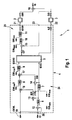
- the FIG. 1 shows a block diagram of a simulation of a hybrid drive 1 with two drive machines 2, 3, wherein the first drive machine is designed as an electric machine 2 and the second drive machine as an internal combustion engine 3.
- the drive machines 2, 3 are coordinated by means of a coordinating drive device 4 with a ride comfort filter 5, a plurality of comparison units 6, 7, 8, 9, 10, 11, a plurality of subtraction units 12, 13, 14, 15 and several adder units 16, 17.
- the comparison units 6, 8, 11 compare two input values and output the higher input value as the output value, the comparison units 7, 9, 10 the lower input value.
- the actual moments (internal combustion engine base torque EtB and actual electric machine torque EMt) are added via a transmission 18 to an output torque (hybrid drive cumulative torque) tS.
- the drive device 4 has an input 19, in which the signal enters a moment specification of the charging strategy in the on-board network maintenance operation tDEML. Furthermore, the drive device 4 has an input 20, in which a signal of a set torque tD is received. This target torque tD can come, for example, from an accelerator pedal with which the driver of the motor vehicle prescribes a driver's desired torque. At the output 21 of the control device 4, this outputs to the electric machine-desired torque tDEM proportional signal to the electric machine 2 and at the output 22 to the engine nominal torque tLE proportional signal to the engine 3 from. At the input 23, a signal proportional to the engine base torque A is fed back into the drive device 4.
- the driver Via the input 20, the driver specifies a setpoint torque tD for the hybrid drive summation torque tS.
- An ignition angle intervention in the internal combustion engine 3 is not carried out in the example considered, thus the actual torque of the internal combustion engine 3 corresponds to the engine base torque EtB, which is generated at an ideal ignition angle.
- the base torque EtB depends on the air charge and follows the target engine torque tLE delayed due to the limited dynamics of the air path.
- the transmission behavior from the target engine torque tLE to the base torque EtB is approximated by a series connection of a dead time element with a dead time of 80 ms and a PT1 element with a time constant of 200 ms in block 3 (internal combustion engine).
- the Torque control of the electric machine 2 takes place in comparison to the internal combustion engine 3 with high dynamics.
- the transmission behavior from the desired electrical machine torque tDEM to the actual electric machine torque EMt is approximately modeled in block 2 (electrical machine) by a PT1 element with a time constant of 20 ms.
- the actual engine torque EtB and the actual electric machine torque EMt add to the total torque tS.
- An operating / charging strategy determines depending on the energy requirements of the electrical system and other factors influencing a torque of a target torque tDEML for the electric machine 2.
- the operating / charging strategy works optimized for fuel consumption and with regard to low exhaust emissions and will not be further described here.
- the determination of the setpoint torque tDEML forms part of the first subarea of the operating range of the electrical machine (vehicle electrical system maintenance operation).
- a first set of (long-term) moment and / or performance limits can be taken into account.
- the torque specification of the charging strategy tDEML is added in a first coordination stage with the opposite sign to the desired torque tD of the driver, the sum results in a nominal torque for the internal combustion engine 3.
- the driver requests a very high target torque tD of the hybrid drive 1 , the determined target engine torque exceeds the maximum possible engine base torque EtB max at the current rotational speed and in stationary operation.
- the boosting torque tDB is additionally applied to the electric machine via the adder unit 17 via the illustrated transverse path.
- a further limitation limits the torque specification of the electric machine 2 determined in this way to the torque limit EMt max S valid for the boost operation (medium term).
- the torque specification tDEML of the charging strategy is not adhered to since the additional boost torque tDB is effective.
- the limited energy content of the electrical energy storage generally decreases.
- a reduction of the boost mode after the end of the operating time of the boost mode is provided.
- a corresponding procedure is provided for the recuperation of the boost and / or recuperation operation, with a valid for the recuperation (medium-term) torque limit EMt min S and a minimum engine base torque EtB min , resulting in a Rekuperationsmoment tDR. Measures for the coordinated transition to the Zündwinkels Georgtver ein or overrun fuel cut at a negative engine target torque are not shown.
- a second set of (medium-term) torque and / or power limits of the electric machine 2 consisting of EMt max S and EMt min S, applies in the FIG.
- the setpoint torque tDF deviates from the sum of the setpoint torque (tDEMS + tDES) output by the second coordination stage. Due to the pronounced dynamic behavior of the internal combustion engine 3 - the intake manifold dynamics - a specially adapted engine target torque tLE is determined with corresponding dynamic curve of the driving comfort filter.
- the instation equalization of the transient compensation mode takes place, in which the subtraction unit 15 generates the difference between the actual torque of the internal combustion engine EtB and the filtered sum-desired torque tDF.
- the third coordination stage 25 for the transient equalization operation thus formed has its own set of (short-term) torque and / or power limits (in which FIG. 1 only moments are considered) consisting of EMt max and EMt min , where: EMT min ⁇ EMT min ⁇ S ⁇ tDEML ⁇ EMT Max ⁇ S ⁇ EMT Max
- the FIG. 2 shows a diagram in which the functions of the target torque tDF, the actual engine torque EtB, the actual electric motor torque EMt and the total hybrid driving torque tS are shown, wherein the abscissa represents the time in seconds (s) and the ordinate the torques in Newton meters (Nm) are removed. It shows the FIG. 2 a positive jump of the driver-determined set torque tD from 50 Nm to 300 Nm.
- the actual torque of the internal combustion engine EtB increases according to the intake manifold dynamics (simulated by assuming a dead time and the curve of a PT1 element) to 200 Nm and approaches asymptotically to the target torque (the target value) tDES.
- the sum torque tS corresponds to a good approximation to the filtered sum-desired torque tDF. It is achieved a high dynamic.
- the resulting engine base torque EtB (function 27) and the actual electric machine torque EMt (function 28) are complementary to the hybrid drive cumulative torque tS (function 29).
- the function 29 essentially corresponds to the course of the filtered desired torque tDF (function 30).
- FIG. 3 shows a corresponding jump of the driver specified torque tD (function 31), but in istregeiiem boost operation.
- the engine base torque EtB corresponds to function 27 of the diagram of FIG. 2
- the actual electric motor torque EMt (function 33) increases only for instation equalization (short-term), then goes back to -10 Nm, so that the resulting hybrid drive summation torque tS (function 34), which is substantially the target torque after filtering tDF (function 35) increases to 190 Nm according to the transient compensation operation.
- the FIG. 3 shows that the Instationäraus GmbH according to the invention also takes place in saucetem boost operation.
Landscapes
- Engineering & Computer Science (AREA)
- Chemical & Material Sciences (AREA)
- Combustion & Propulsion (AREA)
- Transportation (AREA)
- Mechanical Engineering (AREA)
- Automation & Control Theory (AREA)
- Power Engineering (AREA)
- Electric Propulsion And Braking For Vehicles (AREA)
- Hybrid Electric Vehicles (AREA)
- Control Of Vehicle Engines Or Engines For Specific Uses (AREA)
Claims (9)
- Procédé d'entraînement d'une propulsion hybride (1) de véhicule automobile comportant un moteur à combustion interne (3), au moins un moteur électrique (2) et au moins un accumulateur électrique, le moteur électrique (2) et l'accumulateur électrique appartenant à un réseau de bord du véhicule automobile, le procédé comprenant les étapes suivantes :division du fonctionnement du moteur électrique (2) en sous-zones connexes ;caractérisé par les étapes suivantes :a) mode de fonctionnement de compensation non stationnaire ;b) mode de fonctionnement d'élan et/ou de récupération ;c) mode de fonctionnement de maintien du réseau de bord ;affectation de limites de couple et/ou de puissance (EMtmaxS, EMtminS) individuelles du moteur électrique (2) dans au moins deux sous-zones ; etvalidation et/ou influencement des limites de couple et/ou de puissance (EmtmaxS, EMtminS) respectives des sous-zones en fonction de l'état momentané de l'accumulateur électrique et/ou du moteur électrique (2) et/ou du réseau de bord.
- Procédé selon la revendication 1, caractérisé en ce que le mode de fonctionnement de compensation non stationnaire est un mode de fonctionnement à court terme, que le mode de fonctionnement d'élan et/ou de récupération est un mode de fonctionnement à moyen terme et que le mode de fonctionnement de maintien du réseau de bord est un mode de fonctionnement à long terme.
- Procédé selon l'une quelconque des revendications précédentes, caractérisé en ce que le mode de fonctionnement à court terme dure au maximum deux secondes, que le mode de fonctionnement à moyen terme dure au maximum une minute et que le mode de fonctionnement à long terme dure plus longuement qu'une minute.
- Procédé selon l'une quelconque des revendications précédentes, caractérisé en ce qu'une transition de la limite de couple et/ou de puissance (EMtmaxS, EMtminS) se produit en continu pour atteindre une limite de couple et/ou de puissance (EMtmaxS, EMtminS) inférieure ou supérieure.
- Procédé selon l'une quelconque des revendications précédentes, caractérisé en ce qu'au moins une sous-zone supplémentaire est prévue, le moteur électrique (2) se voyant affecté dans cette sous-zone une limite de couple et/ou de puissance (EMtmaxS. EMtminS) correspondante.
- Procédé selon l'une quelconque des revendications précédentes, caractérisé en ce que la sous-zone supplémentaire est un mode de fonctionnement extérieur dans lequel une intervention externe se produit sur la propulsion hybride (1).
- Procédé selon l'une quelconque des revendications précédentes, caractérisé en ce que la séquence de validation et/ou d'influencement des limites de couple et/ou de puissance (EMtmaxS, EMtminS) des sous-zones se produit successivement pour les sous-zones avec des limites de couple et/ou de puissance (EMtmaxS, EMtminS) toujours plus importantes.
- Procédé selon l'une quelconque des revendications précédentes, caractérisé en ce que la séquence de validation et/ou d'influencement des limites de couple et/ou de puissance (EMtmaxS, EMtminS) respectives des sous-zones se produit successivement pour les sous-zones avec des durées de fonctionnement toujours plus courtes.
- Procédé selon l'une quelconque des revendications précédentes, caractérisé en ce que le moteur électrique (2) prend la forme du générateur et du moteur électrique de la propulsion hybride (1).
Applications Claiming Priority (2)
| Application Number | Priority Date | Filing Date | Title |
|---|---|---|---|
| DE102006044427A DE102006044427A1 (de) | 2006-09-21 | 2006-09-21 | Verfahren zum Betreiben eines Hybridantriebs eines Kraftfahrzeugs |
| PCT/EP2007/057681 WO2008034661A1 (fr) | 2006-09-21 | 2007-07-25 | procédé d'utilisation d'un entraînement hybride sur un véhicule automobile |
Publications (2)
| Publication Number | Publication Date |
|---|---|
| EP2066543A1 EP2066543A1 (fr) | 2009-06-10 |
| EP2066543B1 true EP2066543B1 (fr) | 2013-09-11 |
Family
ID=38606670
Family Applications (1)
| Application Number | Title | Priority Date | Filing Date |
|---|---|---|---|
| EP07787907.0A Active EP2066543B1 (fr) | 2006-09-21 | 2007-07-25 | Procédé d'entraînement d'une propulsion hybride de véhicule automobile |
Country Status (7)
| Country | Link |
|---|---|
| US (1) | US8419590B2 (fr) |
| EP (1) | EP2066543B1 (fr) |
| JP (1) | JP2010503581A (fr) |
| KR (1) | KR20090064545A (fr) |
| CN (1) | CN101516702B (fr) |
| DE (1) | DE102006044427A1 (fr) |
| WO (1) | WO2008034661A1 (fr) |
Families Citing this family (24)
| Publication number | Priority date | Publication date | Assignee | Title |
|---|---|---|---|---|
| DE102007042350A1 (de) | 2007-09-06 | 2009-03-12 | Robert Bosch Gmbh | Verfahren zur dynamischen Momentenkoordination von Aggregaten eines Hybridantriebs eines Fahrzeugs und entsprechende Vorrichtung |
| DE102008041897A1 (de) * | 2008-09-09 | 2010-03-11 | Robert Bosch Gmbh | Verfahren zum Betreiben eines Antriebs eines Kraftfahrzeugs sowie Antriebsvorrichtung und elektronisches Steuergerät |
| DE102008042056A1 (de) | 2008-09-12 | 2010-03-18 | Robert Bosch Gmbh | Vorrichtung und Verfahren zum Betrieb eines Antriebes mit einer elektrisch antreibbaren Achse |
| JP4726966B2 (ja) | 2009-01-30 | 2011-07-20 | エンパイア テクノロジー ディベロップメント エルエルシー | ハイブリッド車両用駆動装置、ハイブリッド車両及び駆動方法 |
| US8698437B2 (en) * | 2009-05-15 | 2014-04-15 | Siemens Industry, Inc. | System and method for providing auxiliary power by regeneration power management in mobile mining equipment |
| DE102009057174A1 (de) | 2009-12-05 | 2011-06-09 | Volkswagen Ag | Verfahren und Vorrichtung zur Steuerung von Hybrid-Funktionen in einem Kraftfahrzeug |
| DE102010006305B4 (de) | 2010-01-30 | 2015-02-05 | Audi Ag | Verfahren zum Betreiben eines Hybridantriebs eines Fahrzeugs |
| DE102010030382A1 (de) * | 2010-06-23 | 2011-12-29 | Zf Friedrichshafen Ag | Verfahren zum Betreiben eines Antriebsstrangs |
| DE102010031545A1 (de) * | 2010-07-20 | 2012-01-26 | Sb Limotive Company Ltd. | Verfahren zur Zustandsüberwachung von Antriebssystemen, Batterie mit einem Modul zur Zustandsüberwachung sowie ein Kraftfahrzeug mit einer entsprechenden Batterie |
| DE102011002541A1 (de) * | 2011-01-12 | 2012-07-12 | Zf Friedrichshafen Ag | Verfahren zum Betreiben eines Hybridantriebs sowie Steuerungseinrichtung eines Hybridantriebs |
| US9126587B2 (en) | 2011-12-15 | 2015-09-08 | Ford Global Technologies, Llc | Hybrid vehicle drive control system and method for providing motor torque boost compensating for engine delay and torque exceeding maximum engine torque |
| US20130297125A1 (en) * | 2012-05-07 | 2013-11-07 | Ford Global Technologies, Llc | Torque filling and torque coordination during transients in a hybrid vehicle |
| FR2994404B1 (fr) * | 2012-08-13 | 2014-08-08 | Peugeot Citroen Automobiles Sa | Procede de limitation de couple d'une machine electrique de vehicule hybride, comportant des limites de couple nominal et crete |
| FR2994545B1 (fr) * | 2012-08-14 | 2014-08-08 | Peugeot Citroen Automobiles Sa | Procede de limitation de couple d'une machine electrique de vehicule hybride, dans le cas d'une forte demande en couple |
| DE102013000379A1 (de) * | 2013-01-07 | 2014-07-10 | Getrag Getriebe- Und Zahnradfabrik Hermann Hagenmeyer Gmbh & Cie Kg | Vorrichtung und Verfahren zum schlupffreien Übertragen eines maximalen Antriebsmoments |
| GB2511829B (en) * | 2013-03-14 | 2015-11-25 | Jaguar Land Rover Ltd | Vehicle speed control system |
| WO2014158827A1 (fr) * | 2013-03-14 | 2014-10-02 | Allison Transmission, Inc. | Système et procédé de compensation du temps de réponse du turbo dans les véhicules hybrides |
| US20150039172A1 (en) * | 2013-08-05 | 2015-02-05 | Parker-Hannifin Corporation | Hybrid drive behicle control method and system |
| ITBO20130446A1 (it) * | 2013-08-06 | 2015-02-07 | Magneti Marelli Spa | Metodo di controllo di un veicolo ibrido |
| KR101664708B1 (ko) * | 2015-06-17 | 2016-10-12 | 현대자동차주식회사 | 하이브리드 차량의 제어 방법 |
| DE102016225953A1 (de) * | 2016-10-14 | 2018-04-19 | Continental Automotive Gmbh | Vereinfachte Regelstrategie für ein Hybrid-Fahrzeug für verringerte Emissionswerte |
| DE102016223632A1 (de) * | 2016-11-29 | 2018-05-30 | Bayerische Motoren Werke Aktiengesellschaft | Verfahren zur Steuerung eines Hybridantriebs eines Kraftfahrzeugs sowie Hybridantrieb eines Kraftfahrzeugs |
| US11794566B2 (en) * | 2019-01-16 | 2023-10-24 | Saudi Arabian Oil Company | System and method for employing gasoline compression ignition in a hybrid electric vehicle |
| KR102422145B1 (ko) * | 2021-04-06 | 2022-07-19 | 현대자동차주식회사 | 전동화 차량의 런치 컨트롤 방법 및 전동화 차량 |
Family Cites Families (12)
| Publication number | Priority date | Publication date | Assignee | Title |
|---|---|---|---|---|
| EP0846065B1 (fr) | 1995-08-31 | 2001-11-07 | Continental ISAD Electronic Systems GmbH & Co. oHG | Systeme anti-patinage utilisant un moteur electrique, destine a une automobile |
| US6116368A (en) * | 1997-11-21 | 2000-09-12 | Lockheed Martin Corp. | Electric vehicle with battery regeneration dependent on battery charge state |
| US6196344B1 (en) | 1999-09-10 | 2001-03-06 | Ford Global Technologies, Inc. | Control system and method for a hybrid electric vehicle |
| JP3745309B2 (ja) * | 2001-06-12 | 2006-02-15 | 本田技研工業株式会社 | 燃料電池自動車の制御装置 |
| JP3904192B2 (ja) * | 2001-11-05 | 2007-04-11 | 本田技研工業株式会社 | 車両駆動装置 |
| JP3956796B2 (ja) * | 2001-12-26 | 2007-08-08 | アイシン・エィ・ダブリュ株式会社 | ハイブリッド型車両駆動制御装置、ハイブリッド型車両駆動制御方法及びそのプログラム |
| DE10261278B4 (de) | 2002-12-27 | 2018-12-13 | Volkswagen Ag | Verfahren und Vorrichtung zur Drehmomentänderung |
| JP4013905B2 (ja) * | 2003-05-21 | 2007-11-28 | トヨタ自動車株式会社 | 動力出力装置およびその制御方法並びに自動車 |
| JP3665060B2 (ja) * | 2003-07-04 | 2005-06-29 | 本田技研工業株式会社 | ハイブリッド車両の制御装置 |
| US7305873B2 (en) * | 2004-05-15 | 2007-12-11 | General Motors Corporation | Method for dynamically determining peak output torque in an electrically variable transmission |
| DE102004048606B4 (de) | 2004-10-06 | 2019-05-09 | Robert Bosch Gmbh | Hybrider Antriebsstrang für ein Kraftfahrzeug |
| US8145375B2 (en) * | 2007-11-01 | 2012-03-27 | GM Global Technology Operations LLC | System constraints method of determining minimum and maximum torque limits for an electro-mechanical powertrain system |
-
2006
- 2006-09-21 DE DE102006044427A patent/DE102006044427A1/de not_active Withdrawn
-
2007
- 2007-07-25 US US12/442,398 patent/US8419590B2/en active Active
- 2007-07-25 WO PCT/EP2007/057681 patent/WO2008034661A1/fr active Application Filing
- 2007-07-25 KR KR1020097005717A patent/KR20090064545A/ko not_active Application Discontinuation
- 2007-07-25 CN CN2007800353209A patent/CN101516702B/zh not_active Expired - Fee Related
- 2007-07-25 JP JP2009528659A patent/JP2010503581A/ja active Pending
- 2007-07-25 EP EP07787907.0A patent/EP2066543B1/fr active Active
Also Published As
| Publication number | Publication date |
|---|---|
| JP2010503581A (ja) | 2010-02-04 |
| CN101516702B (zh) | 2012-09-26 |
| EP2066543A1 (fr) | 2009-06-10 |
| KR20090064545A (ko) | 2009-06-19 |
| US8419590B2 (en) | 2013-04-16 |
| DE102006044427A1 (de) | 2008-04-03 |
| US20100062896A1 (en) | 2010-03-11 |
| CN101516702A (zh) | 2009-08-26 |
| WO2008034661A1 (fr) | 2008-03-27 |
Similar Documents
| Publication | Publication Date | Title |
|---|---|---|
| EP2066543B1 (fr) | Procédé d'entraînement d'une propulsion hybride de véhicule automobile | |
| EP1966021B1 (fr) | Procede pour faire fonctionner un vehicule hybride | |
| EP1791711B1 (fr) | Procede pour faire fonctionner un entrainement de vehicule et dispositif pour mettre en oeuvre le procede | |
| DE102015222690A1 (de) | Steuern einer Antriebseinrichtung eines Hybridfahrzeuges und Hybridfahrzeug | |
| EP1968839B1 (fr) | Procédé de surveillance de systèmes d'entraînement multimoteur | |
| DE10162017A1 (de) | Vorrichtung und Verfahren zur Regelung der Fahrgeschwindigkeit eines Fahrzeugs | |
| DE102010006305B4 (de) | Verfahren zum Betreiben eines Hybridantriebs eines Fahrzeugs | |
| WO2008122392A1 (fr) | Procédé de commande d'un système d'entraînement de véhicule à moteur | |
| DE102006001201A1 (de) | Verfahren zur Steuerung eines Batterieladungsvorgangs | |
| DE102012212156A1 (de) | System und Verfahren zum Steuern des Drehmoments in einem Hybridfahrzeug | |
| DE102010062337A1 (de) | Verfahren und Vorrichtung zur Änderung der mechanischen Ankopplung eines Antriebaggregates an einen Triebstrang eines Kraftfahrzeuges, dessen Triebstrang mit mindestens zwei Antriebsaggregaten ausgerüstet ist | |
| WO2009053152A1 (fr) | Procédé de fonctionnement d'un dispositif d'entraînement, en particulier d'un dispositif d'entraînement hybride | |
| DE102017116567A1 (de) | Drehmomentänderungen während eines hochschaltens in einem hybridfahrzeug | |
| EP1966018B1 (fr) | Vehicule a entrainement hybride et procede d'utilisation d'un entrainement hybride | |
| WO2007113288A1 (fr) | point de positionnement de la pédale d'accélérateur de véhiculees hybrides | |
| EP3592588B1 (fr) | Procédé de commande d'un véhicule à moteur et véhicule à moteur | |
| DE102005012931A1 (de) | Verfahren zur Steuerung eines Momentenaufbaus eines Hybridfahrzeugs sowie Hybridfahrzeug | |
| DE10037184B4 (de) | Hybridfahrzeug-Steuer/Regel-Vorrichtung | |
| EP2033865B1 (fr) | Procédé de coordination de couple dynamique d'agrégats d'un entraînement hybride d'un véhicule et dispositif correspondant | |
| WO2009053213A2 (fr) | Procédé pour faire fonctionner un dispositif d'entraînement hybride d'un véhicule, et dispositif d'entraînement hybride. | |
| DE102007012303B4 (de) | Verfahren zum Betreiben eines Hybridantriebs eines Fahrzeugs | |
| DE10261278B4 (de) | Verfahren und Vorrichtung zur Drehmomentänderung | |
| EP1539525B1 (fr) | Chaine cinematique d'un vehicule automobile et procede pour commander une chaine cinematique de vehicule automobile | |
| DE102006013677A1 (de) | Verfahren zum Betreiben einer Antriebseinheit eines Hybridfahrzeugs | |
| DE102012014462B4 (de) | Drehzahlregler und Drehzahlregelung für einen Hybridantrieb |
Legal Events
| Date | Code | Title | Description |
|---|---|---|---|
| PUAI | Public reference made under article 153(3) epc to a published international application that has entered the european phase |
Free format text: ORIGINAL CODE: 0009012 |
|
| 17P | Request for examination filed |
Effective date: 20090421 |
|
| AK | Designated contracting states |
Kind code of ref document: A1 Designated state(s): AT BE BG CH CY CZ DE DK EE ES FI FR GB GR HU IE IS IT LI LT LU LV MC MT NL PL PT RO SE SI SK TR |
|
| AX | Request for extension of the european patent |
Extension state: AL BA HR MK RS |
|
| 17Q | First examination report despatched |
Effective date: 20090925 |
|
| DAX | Request for extension of the european patent (deleted) | ||
| REG | Reference to a national code |
Ref country code: DE Ref legal event code: R079 Ref document number: 502007012278 Country of ref document: DE Free format text: PREVIOUS MAIN CLASS: B60W0010080000 Ipc: B60W0020000000 |
|
| GRAP | Despatch of communication of intention to grant a patent |
Free format text: ORIGINAL CODE: EPIDOSNIGR1 |
|
| RIC1 | Information provided on ipc code assigned before grant |
Ipc: B60W 10/26 20060101ALI20130423BHEP Ipc: B60W 10/08 20060101ALI20130423BHEP Ipc: B60W 20/00 20060101AFI20130423BHEP |
|
| INTG | Intention to grant announced |
Effective date: 20130514 |
|
| GRAS | Grant fee paid |
Free format text: ORIGINAL CODE: EPIDOSNIGR3 |
|
| GRAA | (expected) grant |
Free format text: ORIGINAL CODE: 0009210 |
|
| AK | Designated contracting states |
Kind code of ref document: B1 Designated state(s): AT BE BG CH CY CZ DE DK EE ES FI FR GB GR HU IE IS IT LI LT LU LV MC MT NL PL PT RO SE SI SK TR |
|
| REG | Reference to a national code |
Ref country code: GB Ref legal event code: FG4D Free format text: NOT ENGLISH |
|
| REG | Reference to a national code |
Ref country code: CH Ref legal event code: EP |
|
| REG | Reference to a national code |
Ref country code: AT Ref legal event code: REF Ref document number: 631449 Country of ref document: AT Kind code of ref document: T Effective date: 20130915 |
|
| REG | Reference to a national code |
Ref country code: IE Ref legal event code: FG4D Free format text: LANGUAGE OF EP DOCUMENT: GERMAN |
|
| REG | Reference to a national code |
Ref country code: DE Ref legal event code: R096 Ref document number: 502007012278 Country of ref document: DE Effective date: 20131107 |
|
| REG | Reference to a national code |
Ref country code: SE Ref legal event code: TRGR |
|
| PG25 | Lapsed in a contracting state [announced via postgrant information from national office to epo] |
Ref country code: LT Free format text: LAPSE BECAUSE OF FAILURE TO SUBMIT A TRANSLATION OF THE DESCRIPTION OR TO PAY THE FEE WITHIN THE PRESCRIBED TIME-LIMIT Effective date: 20130911 Ref country code: CY Free format text: LAPSE BECAUSE OF FAILURE TO SUBMIT A TRANSLATION OF THE DESCRIPTION OR TO PAY THE FEE WITHIN THE PRESCRIBED TIME-LIMIT Effective date: 20130731 |
|
| REG | Reference to a national code |
Ref country code: NL Ref legal event code: VDEP Effective date: 20130911 |
|
| REG | Reference to a national code |
Ref country code: LT Ref legal event code: MG4D |
|
| PG25 | Lapsed in a contracting state [announced via postgrant information from national office to epo] |
Ref country code: LV Free format text: LAPSE BECAUSE OF FAILURE TO SUBMIT A TRANSLATION OF THE DESCRIPTION OR TO PAY THE FEE WITHIN THE PRESCRIBED TIME-LIMIT Effective date: 20130911 Ref country code: FI Free format text: LAPSE BECAUSE OF FAILURE TO SUBMIT A TRANSLATION OF THE DESCRIPTION OR TO PAY THE FEE WITHIN THE PRESCRIBED TIME-LIMIT Effective date: 20130911 Ref country code: SI Free format text: LAPSE BECAUSE OF FAILURE TO SUBMIT A TRANSLATION OF THE DESCRIPTION OR TO PAY THE FEE WITHIN THE PRESCRIBED TIME-LIMIT Effective date: 20130911 Ref country code: GR Free format text: LAPSE BECAUSE OF FAILURE TO SUBMIT A TRANSLATION OF THE DESCRIPTION OR TO PAY THE FEE WITHIN THE PRESCRIBED TIME-LIMIT Effective date: 20131212 |
|
| PG25 | Lapsed in a contracting state [announced via postgrant information from national office to epo] |
Ref country code: CY Free format text: LAPSE BECAUSE OF FAILURE TO SUBMIT A TRANSLATION OF THE DESCRIPTION OR TO PAY THE FEE WITHIN THE PRESCRIBED TIME-LIMIT Effective date: 20130911 |
|
| PG25 | Lapsed in a contracting state [announced via postgrant information from national office to epo] |
Ref country code: EE Free format text: LAPSE BECAUSE OF FAILURE TO SUBMIT A TRANSLATION OF THE DESCRIPTION OR TO PAY THE FEE WITHIN THE PRESCRIBED TIME-LIMIT Effective date: 20130911 Ref country code: SK Free format text: LAPSE BECAUSE OF FAILURE TO SUBMIT A TRANSLATION OF THE DESCRIPTION OR TO PAY THE FEE WITHIN THE PRESCRIBED TIME-LIMIT Effective date: 20130911 Ref country code: CZ Free format text: LAPSE BECAUSE OF FAILURE TO SUBMIT A TRANSLATION OF THE DESCRIPTION OR TO PAY THE FEE WITHIN THE PRESCRIBED TIME-LIMIT Effective date: 20130911 Ref country code: NL Free format text: LAPSE BECAUSE OF FAILURE TO SUBMIT A TRANSLATION OF THE DESCRIPTION OR TO PAY THE FEE WITHIN THE PRESCRIBED TIME-LIMIT Effective date: 20130911 Ref country code: RO Free format text: LAPSE BECAUSE OF FAILURE TO SUBMIT A TRANSLATION OF THE DESCRIPTION OR TO PAY THE FEE WITHIN THE PRESCRIBED TIME-LIMIT Effective date: 20130911 Ref country code: IS Free format text: LAPSE BECAUSE OF FAILURE TO SUBMIT A TRANSLATION OF THE DESCRIPTION OR TO PAY THE FEE WITHIN THE PRESCRIBED TIME-LIMIT Effective date: 20140111 |
|
| PG25 | Lapsed in a contracting state [announced via postgrant information from national office to epo] |
Ref country code: PL Free format text: LAPSE BECAUSE OF FAILURE TO SUBMIT A TRANSLATION OF THE DESCRIPTION OR TO PAY THE FEE WITHIN THE PRESCRIBED TIME-LIMIT Effective date: 20130911 Ref country code: ES Free format text: LAPSE BECAUSE OF FAILURE TO SUBMIT A TRANSLATION OF THE DESCRIPTION OR TO PAY THE FEE WITHIN THE PRESCRIBED TIME-LIMIT Effective date: 20130911 |
|
| REG | Reference to a national code |
Ref country code: DE Ref legal event code: R097 Ref document number: 502007012278 Country of ref document: DE |
|
| PG25 | Lapsed in a contracting state [announced via postgrant information from national office to epo] |
Ref country code: PT Free format text: LAPSE BECAUSE OF FAILURE TO SUBMIT A TRANSLATION OF THE DESCRIPTION OR TO PAY THE FEE WITHIN THE PRESCRIBED TIME-LIMIT Effective date: 20140113 |
|
| PLBE | No opposition filed within time limit |
Free format text: ORIGINAL CODE: 0009261 |
|
| STAA | Information on the status of an ep patent application or granted ep patent |
Free format text: STATUS: NO OPPOSITION FILED WITHIN TIME LIMIT |
|
| 26N | No opposition filed |
Effective date: 20140612 |
|
| REG | Reference to a national code |
Ref country code: DE Ref legal event code: R097 Ref document number: 502007012278 Country of ref document: DE Effective date: 20140612 |
|
| PG25 | Lapsed in a contracting state [announced via postgrant information from national office to epo] |
Ref country code: DK Free format text: LAPSE BECAUSE OF FAILURE TO SUBMIT A TRANSLATION OF THE DESCRIPTION OR TO PAY THE FEE WITHIN THE PRESCRIBED TIME-LIMIT Effective date: 20130911 |
|
| PG25 | Lapsed in a contracting state [announced via postgrant information from national office to epo] |
Ref country code: LU Free format text: LAPSE BECAUSE OF FAILURE TO SUBMIT A TRANSLATION OF THE DESCRIPTION OR TO PAY THE FEE WITHIN THE PRESCRIBED TIME-LIMIT Effective date: 20140725 |
|
| REG | Reference to a national code |
Ref country code: CH Ref legal event code: PL |
|
| REG | Reference to a national code |
Ref country code: IE Ref legal event code: MM4A |
|
| PG25 | Lapsed in a contracting state [announced via postgrant information from national office to epo] |
Ref country code: CH Free format text: LAPSE BECAUSE OF NON-PAYMENT OF DUE FEES Effective date: 20140731 Ref country code: LI Free format text: LAPSE BECAUSE OF NON-PAYMENT OF DUE FEES Effective date: 20140731 |
|
| PG25 | Lapsed in a contracting state [announced via postgrant information from national office to epo] |
Ref country code: IE Free format text: LAPSE BECAUSE OF NON-PAYMENT OF DUE FEES Effective date: 20140725 |
|
| REG | Reference to a national code |
Ref country code: AT Ref legal event code: MM01 Ref document number: 631449 Country of ref document: AT Kind code of ref document: T Effective date: 20140725 |
|
| PG25 | Lapsed in a contracting state [announced via postgrant information from national office to epo] |
Ref country code: AT Free format text: LAPSE BECAUSE OF NON-PAYMENT OF DUE FEES Effective date: 20140725 |
|
| PG25 | Lapsed in a contracting state [announced via postgrant information from national office to epo] |
Ref country code: MC Free format text: LAPSE BECAUSE OF FAILURE TO SUBMIT A TRANSLATION OF THE DESCRIPTION OR TO PAY THE FEE WITHIN THE PRESCRIBED TIME-LIMIT Effective date: 20130911 |
|
| PG25 | Lapsed in a contracting state [announced via postgrant information from national office to epo] |
Ref country code: BG Free format text: LAPSE BECAUSE OF FAILURE TO SUBMIT A TRANSLATION OF THE DESCRIPTION OR TO PAY THE FEE WITHIN THE PRESCRIBED TIME-LIMIT Effective date: 20130911 |
|
| PG25 | Lapsed in a contracting state [announced via postgrant information from national office to epo] |
Ref country code: MT Free format text: LAPSE BECAUSE OF FAILURE TO SUBMIT A TRANSLATION OF THE DESCRIPTION OR TO PAY THE FEE WITHIN THE PRESCRIBED TIME-LIMIT Effective date: 20130911 |
|
| REG | Reference to a national code |
Ref country code: FR Ref legal event code: PLFP Year of fee payment: 10 |
|
| PG25 | Lapsed in a contracting state [announced via postgrant information from national office to epo] |
Ref country code: BE Free format text: LAPSE BECAUSE OF FAILURE TO SUBMIT A TRANSLATION OF THE DESCRIPTION OR TO PAY THE FEE WITHIN THE PRESCRIBED TIME-LIMIT Effective date: 20140731 Ref country code: TR Free format text: LAPSE BECAUSE OF FAILURE TO SUBMIT A TRANSLATION OF THE DESCRIPTION OR TO PAY THE FEE WITHIN THE PRESCRIBED TIME-LIMIT Effective date: 20130911 Ref country code: HU Free format text: LAPSE BECAUSE OF FAILURE TO SUBMIT A TRANSLATION OF THE DESCRIPTION OR TO PAY THE FEE WITHIN THE PRESCRIBED TIME-LIMIT; INVALID AB INITIO Effective date: 20070725 |
|
| REG | Reference to a national code |
Ref country code: FR Ref legal event code: PLFP Year of fee payment: 11 |
|
| REG | Reference to a national code |
Ref country code: FR Ref legal event code: PLFP Year of fee payment: 12 |
|
| PGFP | Annual fee paid to national office [announced via postgrant information from national office to epo] |
Ref country code: FR Payment date: 20200727 Year of fee payment: 14 Ref country code: GB Payment date: 20200724 Year of fee payment: 14 |
|
| PGFP | Annual fee paid to national office [announced via postgrant information from national office to epo] |
Ref country code: IT Payment date: 20200731 Year of fee payment: 14 Ref country code: SE Payment date: 20200724 Year of fee payment: 14 |
|
| GBPC | Gb: european patent ceased through non-payment of renewal fee |
Effective date: 20210725 |
|
| PG25 | Lapsed in a contracting state [announced via postgrant information from national office to epo] |
Ref country code: GB Free format text: LAPSE BECAUSE OF NON-PAYMENT OF DUE FEES Effective date: 20210725 |
|
| PG25 | Lapsed in a contracting state [announced via postgrant information from national office to epo] |
Ref country code: SE Free format text: LAPSE BECAUSE OF NON-PAYMENT OF DUE FEES Effective date: 20210726 Ref country code: FR Free format text: LAPSE BECAUSE OF NON-PAYMENT OF DUE FEES Effective date: 20210731 |
|
| PG25 | Lapsed in a contracting state [announced via postgrant information from national office to epo] |
Ref country code: IT Free format text: LAPSE BECAUSE OF NON-PAYMENT OF DUE FEES Effective date: 20210725 |
|
| PGFP | Annual fee paid to national office [announced via postgrant information from national office to epo] |
Ref country code: DE Payment date: 20230922 Year of fee payment: 17 |