EP2065786B1 - Mobiles Endgerät und Tasteneingabeverfahren dafür - Google Patents
Mobiles Endgerät und Tasteneingabeverfahren dafür Download PDFInfo
- Publication number
- EP2065786B1 EP2065786B1 EP08009805A EP08009805A EP2065786B1 EP 2065786 B1 EP2065786 B1 EP 2065786B1 EP 08009805 A EP08009805 A EP 08009805A EP 08009805 A EP08009805 A EP 08009805A EP 2065786 B1 EP2065786 B1 EP 2065786B1
- Authority
- EP
- European Patent Office
- Prior art keywords
- display unit
- mobile terminal
- display
- controller
- touchscreen
- Prior art date
- Legal status (The legal status is an assumption and is not a legal conclusion. Google has not performed a legal analysis and makes no representation as to the accuracy of the status listed.)
- Active
Links
Images


Classifications
-
- H—ELECTRICITY
- H04—ELECTRIC COMMUNICATION TECHNIQUE
- H04B—TRANSMISSION
- H04B1/00—Details of transmission systems, not covered by a single one of groups H04B3/00 - H04B13/00; Details of transmission systems not characterised by the medium used for transmission
- H04B1/38—Transceivers, i.e. devices in which transmitter and receiver form a structural unit and in which at least one part is used for functions of transmitting and receiving
-
- G—PHYSICS
- G06—COMPUTING; CALCULATING OR COUNTING
- G06F—ELECTRIC DIGITAL DATA PROCESSING
- G06F1/00—Details not covered by groups G06F3/00 - G06F13/00 and G06F21/00
- G06F1/16—Constructional details or arrangements
- G06F1/1613—Constructional details or arrangements for portable computers
- G06F1/1633—Constructional details or arrangements of portable computers not specific to the type of enclosures covered by groups G06F1/1615 - G06F1/1626
- G06F1/1684—Constructional details or arrangements related to integrated I/O peripherals not covered by groups G06F1/1635 - G06F1/1675
- G06F1/1686—Constructional details or arrangements related to integrated I/O peripherals not covered by groups G06F1/1635 - G06F1/1675 the I/O peripheral being an integrated camera
-
- G—PHYSICS
- G06—COMPUTING; CALCULATING OR COUNTING
- G06F—ELECTRIC DIGITAL DATA PROCESSING
- G06F1/00—Details not covered by groups G06F3/00 - G06F13/00 and G06F21/00
- G06F1/16—Constructional details or arrangements
- G06F1/1613—Constructional details or arrangements for portable computers
- G06F1/1615—Constructional details or arrangements for portable computers with several enclosures having relative motions, each enclosure supporting at least one I/O or computing function
- G06F1/1616—Constructional details or arrangements for portable computers with several enclosures having relative motions, each enclosure supporting at least one I/O or computing function with folding flat displays, e.g. laptop computers or notebooks having a clamshell configuration, with body parts pivoting to an open position around an axis parallel to the plane they define in closed position
-
- G—PHYSICS
- G06—COMPUTING; CALCULATING OR COUNTING
- G06F—ELECTRIC DIGITAL DATA PROCESSING
- G06F1/00—Details not covered by groups G06F3/00 - G06F13/00 and G06F21/00
- G06F1/16—Constructional details or arrangements
- G06F1/1613—Constructional details or arrangements for portable computers
- G06F1/1633—Constructional details or arrangements of portable computers not specific to the type of enclosures covered by groups G06F1/1615 - G06F1/1626
- G06F1/1637—Details related to the display arrangement, including those related to the mounting of the display in the housing
- G06F1/1647—Details related to the display arrangement, including those related to the mounting of the display in the housing including at least an additional display
- G06F1/1649—Details related to the display arrangement, including those related to the mounting of the display in the housing including at least an additional display the additional display being independently orientable, e.g. for presenting information to a second user
-
- G—PHYSICS
- G06—COMPUTING; CALCULATING OR COUNTING
- G06F—ELECTRIC DIGITAL DATA PROCESSING
- G06F1/00—Details not covered by groups G06F3/00 - G06F13/00 and G06F21/00
- G06F1/16—Constructional details or arrangements
- G06F1/1613—Constructional details or arrangements for portable computers
- G06F1/1633—Constructional details or arrangements of portable computers not specific to the type of enclosures covered by groups G06F1/1615 - G06F1/1626
- G06F1/1662—Details related to the integrated keyboard
- G06F1/1671—Special purpose buttons or auxiliary keyboards, e.g. retractable mini keypads, keypads or buttons that remain accessible at closed laptop
-
- G—PHYSICS
- G06—COMPUTING; CALCULATING OR COUNTING
- G06F—ELECTRIC DIGITAL DATA PROCESSING
- G06F1/00—Details not covered by groups G06F3/00 - G06F13/00 and G06F21/00
- G06F1/16—Constructional details or arrangements
- G06F1/1613—Constructional details or arrangements for portable computers
- G06F1/1633—Constructional details or arrangements of portable computers not specific to the type of enclosures covered by groups G06F1/1615 - G06F1/1626
- G06F1/1675—Miscellaneous details related to the relative movement between the different enclosures or enclosure parts
- G06F1/1677—Miscellaneous details related to the relative movement between the different enclosures or enclosure parts for detecting open or closed state or particular intermediate positions assumed by movable parts of the enclosure, e.g. detection of display lid position with respect to main body in a laptop, detection of opening of the cover of battery compartment
-
- G—PHYSICS
- G06—COMPUTING; CALCULATING OR COUNTING
- G06F—ELECTRIC DIGITAL DATA PROCESSING
- G06F3/00—Input arrangements for transferring data to be processed into a form capable of being handled by the computer; Output arrangements for transferring data from processing unit to output unit, e.g. interface arrangements
- G06F3/01—Input arrangements or combined input and output arrangements for interaction between user and computer
- G06F3/048—Interaction techniques based on graphical user interfaces [GUI]
- G06F3/0487—Interaction techniques based on graphical user interfaces [GUI] using specific features provided by the input device, e.g. functions controlled by the rotation of a mouse with dual sensing arrangements, or of the nature of the input device, e.g. tap gestures based on pressure sensed by a digitiser
- G06F3/0488—Interaction techniques based on graphical user interfaces [GUI] using specific features provided by the input device, e.g. functions controlled by the rotation of a mouse with dual sensing arrangements, or of the nature of the input device, e.g. tap gestures based on pressure sensed by a digitiser using a touch-screen or digitiser, e.g. input of commands through traced gestures
Definitions
- the present invention relates to a mobile terminal, computer program product and method for making key inputs in a multi-input manner by pressing mechanical buttons, and performing touch screen inputs while holding the mobile terminal.
- Mobile terminals may be configured to perform various functions. Such functions may include a data and voice communications, capturing images or videos through a camera, voice or other audio storage, music file reproduction, image or video displays, and the like. Some mobile terminals may be capable of executing games while others may be implemented as multimedia devices. Recently, mobile terminals have been configured to receive broadcast or multicast signals to allow users to watch video or television programs.
- buttons such as for text inputting
- the user when performing key inputting by pressing buttons (such as for text inputting), the user typically holds his mobile terminal in both hands and uses both thumbs to press buttons on a keypad
- the user when performing key inputting via touch screen inputs, the user typically holds his mobile phone in one hand and uses his other hand to make touch screen inputs (e.g., using his finger tips or a stylus to touch on-screen buttons, using a stylus to write text, etc.).
- the present invention is related to a method, device and computer program product for transferring a currently displayed first display from a first touchscreen of a first display unit on an outer surface of a first body of a device to a second display unit on an inner surface of the first body of the device when the device is opened, and subsequently executing a predetermined function upon receiving a first touch input to the first touchscreen.
- a mobile terminal allowing a user to input keys in a multi-input manner, for example, both by pressing buttons and by performing a touch operation while holding the mobile terminal in his hand, and its key input method are provided.
- a mobile terminal allowing a user to perform touch inputs with fingers that are not currently used for performing key button inputs, while holding the mobile terminal having a Qwerty keyboard, and its key input method are provided herein.
- a mobile terminal having displays on front and rear surfaces of a folder which is opened and closed in a foldable manner, wherein an output is changed from the front display to the rear display according to whether or not the folder is opened and a touch input is performed through the front display, and its key input method are provided herein.
- a mobile terminal having displays on front and rear surface of a folder, wherein the same or different information are displayed on the both displays when the folder is opened, and a touch input is received through at least one display and a particular function outputted to the other display is executed, and its key input method are provided.
- a mobile terminal includes: a first body including first and second display units on front and rear surfaces thereof and having at least one side opened with respect to a second body; and a controller that changes an output from the first to the second display when the first body is opened, and executing a particular function upon receiving a touch input to the first display.
- a mobile terminal including a first body having at least one side opened with respect to a second body and including first and second display units on front and rear surfaces thereof, wherein when the first body is opened, a controller changes an output of the first display to the second display, detects a touch input on the first display to display the touch input information on the second display, and executes a particular function displayed on the second display according to a touch input position or a touch method.
- the present invention has the following advantages.
- the user when performing key inputs in the mobile terminal, the user can perform key inputs in a multi-manner by using buttons or touches while maintaining the way the user holds the mobile terminal, to thus improve user convenience.
- an output can be changed from the front display to the rear display according to whether or not the folder is opened, and a touch input can be received through the front display to execute a particular function outputted on the rear display, thus improving user convenience.
- the same or different information may be displayed on both displays, and a touch input can be received through at least one display to execute a particular function outputted on the other display.
- FIG. 1 is a block diagram of a mobile terminal according to an embodiment of the present invention.
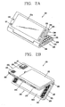
- FIG. 2A is a front perspective view of the mobile terminal according to an embodiment of the present invention.
- FIG. 2B is a rear view of the mobile terminal of FIG. 2A ;
- FIG. 3 is an exemplary view of a wireless communication system operable with the mobile terminal according to an embodiment of the present invention
- FIG. 4A is a front perspective view for explaining a holding pattern when a keypad of the mobile terminal is manipulated according to an embodiment of the present invention
- FIG. 4B is a rear perspective view for explaining a holding pattern when a touch is inputted to the mobile terminal according to an embodiment of the present invention
- FIG. 5 is a flow chart illustrating the process of an operation of the mobile terminal according to an embodiment of the present invention.
- FIG. 6 is an exemplary view for explaining an operation for dividing and controlling a screen area of the mobile terminal according to an embodiment of the present invention.
- FIG. 7 is an exemplary view for explaining an operation of controlling a plurality of displays of the mobile terminal according to an embodiment of the present invention.
- FIG. 1 is a block diagram of a mobile terminal according to an embodiment of the present invention.
- the mobile terminal may be implemented in various forms.
- the terminals according to the exemplary embodiment of the present invention may include mobile phones, smart phones, notebook computers, DMB (Digital Multimedia Broadcasting) terminals, PDAs (Personal Digital Assistants), PMPs (Portable Multimedia Players), navigation, and the like.
- DMB Digital Multimedia Broadcasting
- PDAs Personal Digital Assistants
- PMPs Portable Multimedia Players
- the mobile terminal 100 as shown in FIG. 1 may comprise a wireless communication unit 110, an audio/video (A/V) input unit 120, a user input unit 130, a sensing unit 140, an output unit 150, a memory 160, an interface unit 170, a controller 180, and a power supply unit 190, and the like.
- A/V audio/video
- the mobile terminal as shown in FIG. 1 includes various elements. However, it is understood that implementing all the illustrated elements is not a requirement. Namely, the mobile terminal may be implemented with greater or fewer elements.
- the wireless communication unit 110 may include one or more components which permits wireless communication between the mobile terminal 100 and a wireless communication system or a network in which the mobile terminal is located.
- the wireless communication unit may include a broadcast receiving module 111, a mobile communication module 112, a wireless internet module 113, a short-range communication module 114 and a location information module 115.
- the broadcast receiving module 111 receives a broadcast signal and/or broadcast associated information from an external broadcast management server via a broadcast channel.
- the broadcast channel may include a satellite channel and a terrestrial channel.
- the broadcast management server may refer to a server that generates and transmits a broadcast signal and/or broadcast associated information or a server that receives a pre-generated broadcast signal and/or broadcast associated information and sends them to the mobile terminal.
- the broadcast associated information may include information associated with a broadcast channel, a broadcast program, or a broadcast service provider, etc.
- the broadcast signal may include not only a TV broadcast signal, a radio broadcast signal, and a data broadcast signal, but also a broadcast signal obtained by combining the data broadcast signal to the TV broadcast signal or the radio broadcast signal.
- the broadcast associated information may be provided via a mobile communication network, and in this case, it may be received by the mobile communication module 112.
- the broadcast associated information may exist in various formats.
- the broadcast associated information may exist in such formats as Electronic Program Guide (EPG) of Digital Multimedia Broadcasting (DMB), Electronic Service Guide (ESG) of Digital Video Broadcast-Handheld (DVB-H), and the like.
- EPG Electronic Program Guide
- DMB Digital Multimedia Broadcasting
- ESG Electronic Service Guide
- DVD-H Digital Video Broadcast-Handheld
- the broadcast receiving module 111 receives broadcast signals by using various types of broadcast systems.
- the broadcast receiving module 111 may receive digital broadcast signals by using digital broadcast systems such as Digital Multimedia Broadcasting-terrestrial (DMB-T), Digital Multimedia Broadcasting-satellite (DMB-S), Media Forward Link Only (MediaFLO TM ), Digital Video Broadcast-handheld (DVB-H), Integrated Services Digital Broadcast-Terrestrial (ISDB-T), and the like.
- the broadcast receiving module 111 may be configured to be suitable for certain broadcast systems that provide broadcast signals, as well as for the digital broadcasting systems.
- Broadcast signals and/or broadcast associated information received via the broadcast receiving module 111 may be stored in the memory 160.
- the mobile communication module 112 transmits/receives radio signals to/from at least one of a base station, an external mobile terminal and a server in a mobile communication network, and the like.
- the radio signals may include a voice call signal, a video call signal, or various formats of data according to transmission/reception of text/multimedia messages.
- the wireless Internet module 113 supports wireless network access. This module may be internally or externally coupled to the mobile terminal.
- the short-range communication module 114 refers to a module for supporting short range communications.
- Some examples of short-range communication technology includes Bluetooth TM , Radio Frequency IDentification (RFID), Infrared Data Association (IrDA), Ultra-WideBand (UWB), ZigBee TM , and the like.
- the location information module 115 is a module for checking or acquiring a location of the mobile terminal.
- the location information module 115 may be embodied by using a GPS (Global Positioning System) module that receives location information from a plurality of artificial satellites.
- the location information may include coordinate information represented by the latitude and longitude.
- the GPS module may measure an accurate time and distance from three or more satellites and accurately calculate a current location of the mobile terminal according to trigonometry based on the three different distances. A method of acquiring distance and time information from three satellites and correcting an error with a single satellite may be used.
- the GPS module may acquire an accurate time together with three-dimensional speed information as well as the location of the latitude, longitude and altitude from the location information received from the satellites.
- the AN input unit 120 is configured to input an audio or video signal.
- the A/V input unit 120 may include a camera 121 and a microphone 122.
- the camera 121 processes image data of still pictures or videos obtained by an image capture device in a video capturing mode or an image capturing mode.
- the processed image frames may be displayed on a display unit 151.
- the image frames processed by the camera 121 may be stored in the memory 160 or transmitted via the wireless communication unit 110. Two or more cameras 121 may be provided according to the configuration of the mobile terminal.
- the microphone 122 may receive sounds (audible data) via a microphone (or the like) in a phone call mode, a recording mode, a voice recognition mode, and the like, and process it into audio data.
- the processed audio (voice) data may be converted for output into a format transmittable to a mobile communication base station via the mobile communication module 112 in case of the phone call mode.
- the microphone 122 may include various types of noise canceling (or suppression) algorithms to cancel (or suppress) noise generated in the course of receiving and transmitting audio signals.
- the user input unit 130 may generate key input data inputted by a user to control various operations of the mobile terminal.
- the user input unit 130 may include a keypad, a dome switch, a touch pad (e.g., a touch sensitive member that detects changes in resistance, pressure, capacitance, etc.), a jog wheel, a jog switch, and the like.
- a touch pad e.g., a touch sensitive member that detects changes in resistance, pressure, capacitance, etc.
- the sensing unit 140 detects a current status (or state) of the mobile terminal 100 such as an open/close state of the mobile terminal 100, a location of the mobile terminal 100, presence or absence of user contact with the mobile terminal, orientation of the mobile terminal 100, acceleration/deceleration of the mobile terminal 100, etc., and generates commands or signals for controlling the operation of the mobile terminal 100.
- a current status or state
- the sensing unit 140 may sense whether the slide phone is opened or closed.
- the sensing unit 140 can detect whether or not the power supply unit 190 supplies power or whether or not the interface unit 170 is coupled with an external device.
- the interface unit 170 serves as an interface with at least one external device connected with the mobile terminal 100.
- the external devices may include wired/wireless headset ports, external power charger ports, wired/wireless data ports, memory card ports, ports for connecting a device having an identification module, audio input/output (I/O) ports, video I/O ports, earphone ports, or the like.
- the identification module may be a chip that stores various information for authenticating the authority of using the mobile terminal 100 and may include a user identity module (UIM), a subscriber identity module (SIM) a universal subscriber identity module (USIM), and the like.
- the device having the identification module (referred to as 'identifying device', hereinafter) may be fabricated in the form of a smart card. Accordingly, the identifying device may be connected with the terminal 100 via a port.
- the interface unit 170 may be used to receive inputs (e.g., data, information, power, etc.) from an external device and transfer the received inputs to one or more elements within the mobile terminal 100 or may be used to transfer data from the mobile terminal to an external device.
- the output unit 150 is configured to provide outputs in a visual, audible, and/or tactile manner (e.g., audio signal, video signal, alarm signal, etc.).
- the output unit 150 may include the display unit 151, an audio output module 152, an alarm unit 153, and the like.
- the display unit 151 may output information processed in the mobile terminal 100.
- the display unit 151 may display a User Interface (UI) or a Graphic User Interface (GUI) associated with a call or other communication.
- UI User Interface
- GUI Graphic User Interface
- the display unit 151 may display a captured and/or received image, a UI, a GUI, and the like.
- the display unit 151 may function as both an input device and an output device.
- the display unit 151 may include at least one of a Liquid Crystal Display (LCD), a Thin Film Transistor-LCD (TFT-LCD), an Organic Light Emitting Diode (OLED), a flexible display, a three-dimensional (3D) display, or the like.
- the mobile terminal 100 may include two or more display units (or other display means) according to its embodiment.
- the mobile terminal may include an external display unit 151 a and an internal display unit 151 b.
- the audio output module 152 may output audio data received from the wireless communication unit 110 or stored in the memory 160 in a call signal reception mode, a call mode, a record mode, a voice recognition mode, a broadcast reception mode, and the like. Also, the audio output module 152 may provide audible outputs related to a particular function (e.g., a call signal reception sound, a message reception sound, etc.) performed by the mobile terminal 100.
- the audio output module 152 may include a speaker, a buzzer, or the like.
- the alarm unit 153 may provide outputs to inform about an occurrence of an event of the mobile terminal 100. Typical events may include a call signal reception, a message reception, a key signal input, etc. In addition to audio or video outputs, the alarm unit 153 may provide outputs in a different manner to inform about an occurrence of an event.
- the alarm unit 153 may provide outputs in the form of vibrations (or other tactile means).
- the alarm unit 153 may provide tactile outputs (i.e., vibrations) to inform the user.
- tactile outputs i.e., vibrations
- the user can recognize the occurrence of various events.
- Outputs informing about the occurrence of an event may be also provided via the display unit 151 or the audio output module 152.
- the memory 160 may store software programs or the like used for the processing and controlling performed by the controller 180, or may temporarily store inputted/outputted data (e.g., a phonebook, messages, still images, video, etc.).
- inputted/outputted data e.g., a phonebook, messages, still images, video, etc.
- the memory 160 may include at least one type of storage medium including a flash memory type, a hard disk type, a multimedia card type, a card-type memory (e.g., SD or DX memory, etc), a Random Access Memory (RAM), a Static Random Access Memory (SRAM), a Read-Only Memory (ROM), an Electrically Erasable Programmable Read-Only Memory (EEPROM), a Programmable Read-Only memory (PROM) magnetic memory, a magnetic disk, an optical disk, and the like.
- the mobile terminal 100 may cooperate with a network storage device that performs the storage function of the memory 160 over a network connection.
- the controller 180 typically controls the general operations of the mobile terminal. For example, the controller 180 performs controlling and processing associated with voice calls, data communications, video calls, and the like.
- the controller 180 may include a multimedia module 181 for reproducing (or playing back) multimedia data.
- the multimedia module 181 may be configured within the controller 180 or may be configured to be separated from the controller 180.
- the power supply unit 190 receives external or internal power and supplies power required for the operations of the respective elements under the control of the controller 180.
- the embodiments described herein may be implemented by using at least one of application specific integrated circuits (ASICs), digital signal processors (DSPs), digital signal processing devices (DSPDs), programmable logic devices (PLDs), field programmable gate arrays (FPGAs), processors, controllers, micro-controllers, microprocessors, electronic units designed to perform the functions described herein. In some cases, such embodiments are implemented by the controller 180.
- ASICs application specific integrated circuits
- DSPs digital signal processors
- DSPDs digital signal processing devices
- PLDs programmable logic devices
- FPGAs field programmable gate arrays
- processors controllers, micro-controllers, microprocessors, electronic units designed to perform the functions described herein.
- controller 180 such embodiments are implemented by the controller 180.
- the embodiments such as procedures or functions may be implemented together with separate software modules that allow performing of at least one function or operation.
- Software codes can be implemented by a software application written in any suitable programming language. The software codes may be stored in the memory 160 and executed by the controller 180.
- the mobile terminal may be implemented in a variety of different configurations, including a folder-type, a bar-type, a swing-type, a slide-type, or the like.
- the slide-type mobile terminal will be used as an example in the following description.
- the concepts and features described herein should not be limited to the slide-type mobile terminal, but can be applicable to any type of mobile terminal or other electronic device including the ones as mentioned above.
- FIG. 2A is a front view of the mobile terminal according to an exemplary embodiment.
- the mobile terminal may comprise a first body 200, and a second body configured to be opened from one side of the first body.
- a state in which the first body 200 is disposed to overlap with the second body 205 may be called a closed configuration, and as shown in FIG. 2A , a state in which the first body 200 exposes at least a portion of the second body 205 may be called an open configuration.
- the mobile terminal may usually operate in a standby mode in the closed configuration, but this mode can be released by user manipulation. Also, the mobile terminal may mainly function in a call mode in the open configuration, but may be changed to the standby mode according to user manipulation or after the lapse of a certain time.
- At least one case (housing, casing, cover, etc.) constituting the external appearance of the first body 200 comprises a first front case 220 and a first rear case 225.
- Various electronic components may be installed inside the first front case 220 and the first rear case 225.
- One or more intermediate cases may be additionally disposed between the first front case 220 and the first rear case 225.
- the cases can be formed by injection-molding a synthetic resin, or made of a metallic material such as stainless steel (STS) or titanium (Ti), or some other appropriate materials.
- STS stainless steel
- Ti titanium
- the first display unit 151 a, the second display unit 151b, the audio output module 152, a camera 121 or a first user input unit 210 may be located on the first front case 220 and the first rear case 225 of the first body 200.
- the first display unit 151 a and the second display unit 151 b may have the same size or may have each different size.
- the display units 151 a and 151 b may include LCD, OLED, and the like, that visually displays information.
- a touch pad may be overlaid in a layered manner on the display units 151 a and 151 b to allow the display units 151 a and 151 a to function as a touch screen to input information by the user's touches.
- the controller 180 may output information to the first display unit 151a, and when the first body 200 is opened, the controller 180 may transfer the image(s) displayed on the first display unit 151a from the first display unit 151a to the second display unit 151 b.
- the controller 180 may receive a touch input via the first display unit 151 a and display the touch input information as an indicator (pointer) in a particular shape.
- a particular function may be executed upon receiving the touch input. For example, a game may be displayed on the second display unit 151 b, with a cursor displayed on the game controlled by touch inputs to the first display unit 151a.
- a spreadsheet or document may be displayed on the second display unit 151 b, with a cursor displayed on the spreadsheet or document controlled by touch inputs to the first display unit 151 a.
- a list of music or multimedia files may be displayed on the second display unit 151 b, with a cursor displayed on the list of music or multimedia files controlled by touch inputs to the first display unit 151a.
- a camera display or camera control screen may be displayed on the second display unit 151 b, with a cursor displayed on the camera display or camera control screen controlled by touch inputs to the first display unit 151a.
- the controller 180 may output the same information on the first and second display units 151 a and 151 b.
- the controller 180 may output the same information on the first and second display units 151 a and 151 b.
- two users may conveniently view the same games, document, or movie images with the mobile terminal.
- a camera or video display may be simultaneously displayed on the first and second display units 151 a and 151 b.
- the controller 180 may output different information to the first and second display units 151 a and 151 b.
- a game image may be outputted on the first display unit 151 a and a game setting screen image may be outputted on the second display unit 151 b.
- the game screen image outputted on the first display unit 151a may be controlled by controlling setting outputted on the display unit 151b.
- first display unit 151 a it is not necessary for the touchscreen of first display unit 151 a to control a cursor or pointer on the second display unit 151b. That is, actions relative to data displayed on the second display unit 151 b may be initiated by a touch to the first display unit 151 a, without use of cursor/pointer, or in concert with a cursor/pointer controlled by another element of the device.
- the previously described touch input may be a touch, swipe or drag input.
- buttons may be installed on the face of the device encompassing the first display unit 151 a in areas not occupied by the touchscreen.
- the second display unit 151b may display a background image and a foreground image (i.e., a pop-up window).
- a cursor may also be displayed on the second display unit 151b, with the location of the cursor controlled by touches to the first display unit 151a. Functions may be executed on items beneath the cursor upon receiving a touch input to the first display unit 151a or to a button located on the device. Whether the touch input is correlated to the background or foreground image depending on where the cursor is located.
- the audio output unit 152 may be implemented in the form of a speaker or in a form allowing an ear jack may be inserted.
- the audio output modules 152 may be provided at both sides of the display unit 151a or 151b. At least one output thereof may be selectively controlled by the controller 180. For example, during call communication, voice may be outputted only via the audio output module provided at one side of the display unit 151 a or 151 b. Alternatively, the audio output modules may be configured to output sound related to respective output screen images of the display unit 151 a and 151 b. Of course, in this case, preferably, the sound may be outputted via separated ear jacks, and two users may view different images via the display units provided on front and rear surfaces.
- the camera 121 may be implemented to be suitable for capturing images or video with respect to the user and so on.
- the camera 121 may be implemented at least one of the front surface and the rear surface, and may be implemented on the second body 205 as necessary. Namely, when the first body is in the closed configuration, camera capturing or video call communication can be performed, and even while the first body is in an open configuration, camera capturing and video call communication can be performed.
- the case constituting the external appearance of the second body 205 is formed by a second front case 230 and a second rear case 235.
- a second user input unit 215 may be disposed on a front surface of the second body 205, specifically, on the second front case 230.
- the second user input unit 215 may be implemented as a keypad formed as a Qwerty key arrangement as shown.
- the keypad may be displayed on display including a touchscreen or may be a set of electro-mechanical push buttons.
- the touchpad of the first display unit 151a may control a cursor on the second user input unit 215.
- another display may reside in the inner surface of the lower body. This display residing in the inner surface of the lower body may be in place of or in addition to the second display unit 151b.
- the touchpad of the first display unit 151a may control a cursor on the display residing in the inner surface of the lower body. If the display residing in the inner surface of the lower body is in addition to the second display unit 151b, the touchpad of the first display unit 151 a may control a cursor that moves between the two screens on the interior of the device.
- a third user input unit 245, the short-range communication module 114, the microphone 122, the interface unit 170 may be disposed on at least one of the second front case 230 and the second rear case 235.
- the microphone 122 may be implemented also on the first body 200 in a form suitable for receiving voice of the user or other sounds.
- the first to third user input units 210, 215 and 245 may be generally called the manipulating unit 130, and various methods can be employed for the manipulation unit so long as they can be operated by the user in a tactile manner.
- the user input units 130 can be implemented as a button, a dome switch or touch pad that can receive user commands or information according to user's pressing, pushing or touching, or implemented in the form of a wheel that rotates a key, a jog element, a joystick, or the like.
- the first user input unit 210 is used for inputting commands such as start, end, scroll or the like
- the second user input unit 215 is used for inputting numbers, characters, symbols, or the like
- the third user input unit 245 may operate as a hot key for activating a particular function within the mobile terminal.
- the interface unit 170 may be used as a link (passage or path) through which the terminal can exchange data or the like with an external device.
- the interface unit 170 may be implemented as one of a connection port for connecting an earphone to the mobile terminal via a fixed or wireless means, a port for short-range communications (e.g., an Infrared Data Association (IrDA) port, a Bluetooth TM port, a wireless LAN port, etc.), power supply ports for providing power to the mobile terminal, or the like.
- IrDA Infrared Data Association
- the interface unit 170 may be a card socket for accommodating an external card such as a memory card for storing information.
- the power supply unit 190 for supplying power to the terminal is located at the side portion of the second rear case 235.
- the power supply unit 190 may be, for example, a rechargeable battery that can be detached.
- FIG. 2B is a rear perspective view of the mobile terminal of FIG. 2A according to an exemplary embodiment.
- a camera 121 may additionally be disposed on a rear surface of the second rear case 235 of the second body 205.
- the camera 121 of the second body 205 may have an image capture direction which is substantially the opposite to that of the camera 121 of the first body 200, and may support a different number of pixels as that of the camera 121 of the first body.
- the camera 121 of the first body 200 may be used for low resolution (i.e., supporting a relatively small number of pixels) to quickly capture an image (or video) of the user's face and immediately transmit the same to the other party during video conferencing or the like.
- the camera 121 of the second body 205 may be used for high resolution (i.e., supporting a relatively large number of pixels) in order to capture more detailed (higher quality) images (or video) which typically do not need to be transmitted immediately.
- a flash 250 and a mirror 255 may be additionally disposed adjacent to the camera 121.
- the flash 250 illuminates the subject.
- the mirror 255 allows the user to see himself when he wants to capture his own image (self-image capturing) by using the camera 121 of the second body 205.
- the second camera 121 and so on is disposed on the second body 205, but such configuration is not meant to be limited.
- one or more of the elements which are disposed on the second rear case 235 in the above description, may be mounted on the first body 200, mainly, on the first rear case 225.
- those elements disposed on the first rear case 225 can be protected (or covered) by the second body 205 in the closed configuration.
- the camera module 121 may be configured to rotate (or otherwise be moved) to thus allow image capturing in various directions.
- the second rear case 235 may further include an audio output module 152.
- the audio output module 152 may implement a stereophonic sound function in conjunction with the audio output module 152 of the first body 200, and may be also used for sending and receiving calls in a speaker phone mode.
- a broadcast signal receiving antenna 260 may be disposed at one side or region of the second rear case 235, in addition to an antenna that supports mobile communications.
- the antenna 260 can be configured to be retractable from the second body 205.
- a hinge module 265 may be provided at one side of the first body 200 or the second body 205 to open the first body 200 or the second body 205 and may have such a form that is not exposed.
- a slide mechanism may also be provided at one side of the first body 200 or the second body 205 to open the first body 200 or the second body 205 and may have such a form that is not exposed.
- the mobile terminal 100 as shown in FIGs. 1 to 2B may be configured to operate within a communication system which transmits data via frames or packets, including wired/wireless communication systems and satellite-based communication systems.
- Such communication systems may use different air interfaces and/or physical layers.
- air interfaces utilized by the communication systems include example, frequency division multiple access (FDMA), time division multiple access (TDMA), code division multiple access (CDMA), and universal mobile telecommunications system (UMTS) (in particular, long term evolution (LTE)), and the global system for mobile communications (GSM), and the like.
- FDMA frequency division multiple access
- TDMA time division multiple access
- CDMA code division multiple access
- UMTS universal mobile telecommunications system
- LTE long term evolution
- GSM global system for mobile communications
- a CDMA wireless communication system may include a plurality of mobile terminals 100, a plurality of base stations (BSs) 270, base station controllers (BSCs) 275, and a mobile switching center (MSC) 280.
- the MSC 280 is configured to interface with a public switch telephone network (PSTN) 290.
- PSTN public switch telephone network
- the MSC 280 is also configured to interface with the BSCs 275.
- the BSCs 275 may be coupled to the base stations 270 via backhaul lines.
- the backhaul lines may be configured in accordance with any of several known interfaces including, for example, E1/T1, ATM, IP, PPP, Frame Relay, HDSL, ADSL, or xDSL. It is to be understood that the system as shown in FIG. 3 may include a plurality of BSCs 275.
- Each BS 270 may include one or more sectors, each sector having an omni-directional antenna or an antenna pointed in a particular direction radially away from the BS 270. Alternatively, each sector may include two or more antennas for diversity reception. Each BS 270 may be configured to support a plurality of frequency assignments, and each frequency assignment has a particular spectrum (e.g., 1.25 MHz, 5 MHz, etc).
- the intersection of a sector and frequency assignment may be referred to as a CDMA channel.
- the BS 270 may also be referred to as base station transceiver subsystems (BTSs).
- BTSs base station transceiver subsystems
- the term "base station” may be used to refer collectively to a single BSC 275 and at least one BS 270.
- the BSs may also denote "cell sites". Alternatively, individual sectors of a particular BS 270 may be referred to as a plurality of cell sites.
- a broadcasting transmitter (BT) 295 transmits a broadcast signal to the mobile terminals 100 operating within the system.
- the broadcast receiving module 111 as shown in FIG. 1 is provided within the terminal 100 to receive broadcast signals transmitted by the BT 295.
- FIG. 3 shows several global positioning system (GPS) satellites 300.
- GPS global positioning system
- the GPS module 115 as shown in FIG. 1 is typically configured to cooperate with the satellites 300 to obtain desired position information.
- any technologies that may track the location of the mobile terminals may be used to track the location of the mobile terminals.
- at least one of the GPS satellites 300 may selectively or additionally handle satellite DMB transmission.
- the BSs 270 receive reverse-link signals from various mobile terminals 100.
- the mobile terminals 100 are engaging in calls, messaging, and other communications.
- Each reverse-link signal received by a particular base station 270 is processed within the particular BS 270.
- the resulting data is forwarded to an associated BSC 275.
- the BSC provides call resource allocation and mobility management functionality including the orchestration of soft handoffs between BSs 270.
- the BSCs 275 also route the received data to the MSC 280, which provides additional routing services for interfacing with the PSTN 290.
- the PSTN 290 interfaces with the MSC 280
- the MSC interfaces with the BSCs 275
- the BSCs 275 in turn control the BSs 270 to transmit forward-link signals to the mobile terminals 100.
- FIG. 4A is a front perspective view for explaining a holding pattern when a keypad of the mobile terminal is manipulated according to an embodiment of the present invention
- FIG. 4B is a rear perspective view for explaining a holding pattern when a touch is inputted to the mobile terminal according to an embodiment of the present invention.
- the second user input unit 215 disposed on the front surface of the second front case 230 of the second body 205 may have a keypad.
- the keypad may be configured to have a button for inputting a phone number and a button for inputting a particular function.
- the keypad may be configured as a Qwerty keyboard as shown in FIGs. 2A and 4A .
- the user may open the first body 200 of the mobile terminal and easily and stably hold the second body 205 with both hands as shown in FIG. 4A , whereby the user can simply and quickly manipulated the keypad with both thumbs.
- Key input information inputted via the keypad may be outputted to the second display unit 151 b disposed on the first rear case 225.
- the controller 180 of the mobile terminal may change an output of information, which has been outputted on the first display unit 151 in the closed configuration of the first body 200, to the second display unit 151b.
- the index fingers of both hands are positioned on the front case 220 as shown in FIG. 4B . Specifically, the index fingers of both hands are positioned on the first display unit 151 a.
- the controller 180 may activate the touch input function of the first display unit 151 a and receive a touch by using the index fingers.
- the controller 180 may display the touch input information as pointers 410 of a particular shape on the second display unit 151 b.
- the controller 180 may detect a multi-touch. Namely, the controller 180 may display at least two touch input information inputted with the index fingers of both hands of the user. Or, the controller 180 may selectively recognize the first touch-input finger among the two fingers and may not recognize the later touch-input finger.
- the user may execute a particular menu or a particular function linked to a particular item displayed on the second display unit 151 b through a touch input onto the first display unit 151 a.
- a particular key button of the keypad may be pressed or double touches may be performed with the index fingers positioned on the first display unit 151 a to execute a particular function.
- the double touches refer to successively touching a particular point on the touch screen twice within a particular time.
- the controller 180 may perform multitasking by vertically (up/down) or horizontally (left/right) dividing the screen of the first display unit 151a or the second display unit 151b.
- the screen of the second display unit 151 b may be horizontally divided to output different task screen images (e.g., multimedia contents reproducing, broadcast outputting, message outputting, call information outputting) on each divided screen and control each divided screen upon receiving control inputs from both hands.
- FIG. 5 is a flow chart illustrating the process of an operation of the mobile terminal according to an embodiment of the present invention.
- the controller 180 of the mobile terminal detects whether the mobile terminal including the first and second bodies 200 and 205 is opened, according to which the controller 180 controls the first and second display units 151 a and 151 b provided on the front and rear surfaces of the first body 200.
- the controller 180 While an execution screen image of a particular function is being outputted on the display unit 151a or 151b, if a function related to call communication (e.g., a voice call, a video call, a message reception) or multimedia contents reproducing, as shown in FIG. 6 , the controller 180 divides the single screen into two regions 510 and 520 and outputs the screen image related to the call communication or contents reproducing to one region 520 and the execution screen image of the particular function to another region 510.
- a function related to call communication e.g., a voice call, a video call, a message reception
- multimedia contents reproducing as shown in FIG. 6
- the controller 180 divides the single screen into two regions 510 and 520 and outputs the screen image related to the call communication or contents reproducing to one region 520 and the execution screen image of the particular function to another region 510.
- the functions outputted on the divided screens may be controlled with both hands of the user, respectively.
- different function execution screen images may be outputted on the first and second display units 151 a and 151 b.
- a video reproducing screen image may be outputted on the first display unit 151 a and a game screen image may be outputted on the second display unit 151 b.
- the controller 180 when the first body 200 is in the closed configuration (S101), the controller 180 outputs an execution screen image of a particular function onto the first display unit 151 a (S102).
- the user may manipulate the first user input unit 210 provided on the first front case or may execute a particular function by touching the first display unit 151 a.
- the controller 180 may change the executed screen image of the particular function outputted from the display unit 151 a to the second display unit 151 b so that the second display unit 151 b may output the executed screen image of the particular function (S104).
- step S104 is not performed, and the process continues from step S103 to step S105 described below. That is, when the first body 200 is opened (S103), the controller 180 may not change the screen output but output the same information as that of first display unit 151 a on to the second display unit 151 b.
- each display unit 151a or 151b may output different information.
- the first display unit 151a may output multimedia contents reproducing screen image while the second display unit 151 b may output a screen image related to call communication.
- the controller 180 may maintain the touch input function in an active state as it is (S105).
- the controller 180 may detect a touch input to the first display unit 151 a and display the pointers 410 of a particular shape on the second display unit 151 b (S106).
- the controller 180 may detect a touch inputted through the first display unit 151a and execute a particular function linked to an item on which the pointer 410 is positioned on a screen image outputted from the second display unit 151b (S107).
- the user when performing key inputs in the mobile terminal, the user can perform key inputs in a multi-manner by using buttons or touches while maintaining the way the user holds the mobile terminal, to thus improve user convenience.
- an output can be changed from the front display to the rear display according to whether or not the folder is opened, and a touch input can be received through the front display to execute a particular function outputted on the rear display, thus improving user convenience.
- the same or different information may be displayed on both displays, and a touch input can be received through at least one display to execute a particular function outputted on the other display.
Claims (20)
- Mobiles Endgerät, umfassend:einen ersten Aufbau mit einer Außenfläche und einer Innenfläche;eine erste Anzeigeeinheit an der Außenfläche des ersten Aufbaus, die einen ersten Berührungsbildschirm aufweist;eine zweite Anzeigeeinheit an der Innenfläche des ersten Aufbaus;einen zweiten Aufbau;eine Scharnier- oder Schiebeverbindung, die den ersten und zweiten Aufbau verbindet und dazu ausgebildet ist, einen Benutzer in die Lage zu versetzen, das mobile Endgerät zu öffnen und zu schließen; undeine Steuereinheit, die betriebsmäßig mit der ersten und zweiten Anzeigeeinheit verbunden ist, wobei die Steuereinheit dazu ausgebildet ist, ein Öffnen oder Schließen des mobilen Endgeräts festzustellen, wobei die Steuereinheit weiter dazu ausgebildet ist, eine aktuell gezeigte erste Anzeige von der ersten Anzeigeeinheit zur zweiten Anzeigeeinheit zu übertragen, wenn der erste Aufbau geöffnet wird, und anschließend nach dem Erhalt einer ersten Berührungseingabe am ersten Berührungsbildschirm eine vorbestimmte Funktion auszuführen.
- Mobiles Endgerät nach Anspruch 1, wobei die zweite Anzeigeeinheit umfasst:einen zweiten Berührungsbildschirm.
- Mobiles Endgerät nach Anspruch 1, weiter umfassend:ein elektromechanisches Tastenfeld am zweiten Aufbau; odereine dritte Anzeigeeinheit.
- Mobiles Endgerät nach Anspruch 3, wobei die dritte Anzeigeeinheit umfasst:einen dritten Berührungsbildschirm.
- Mobiles Endgerät nach Anspruch 1, wobei die Steuereinheit dazu ausgebildet ist,
einen ersten Zeiger mit einer vorbestimmten Form auf der zweiten Anzeigeeinheit als vorbestimmte Funktion anzuzeigen und zu steuern, und
eine andere vorbestimmte Funktion an einem auf der zweiten Anzeigeeinheit angegebenen Element nach dem Erhalt einer zweiten Berührungseingabe am ersten Berührungsbildschirm durch den ersten Zeiger zur Ausführung zu bringen. - Mobiles Endgerät nach Anspruch 1, wobei die Steuereinheit dazu ausgebildet ist, gleichzeitig einen ersten und zweiten Zeiger auf der zweiten Anzeigeeinheit in Reaktion auf erste und zweite Berührungseingaben an entsprechenden ersten und zweiten Bereichen des ersten Berührungsbildschirms als vorbestimmte Funktion anzuzeigen und zu steuern.
- Mobiles Endgerät nach Anspruch 1, wobei die Steuereinheit dazu ausgebildet ist, selektiv einen ersten und zweiten Zeiger auf der zweiten Anzeigeeinheit in Reaktion auf erste und zweite Berührungseingaben an entsprechenden ersten und zweiten Bereichen des ersten Berührungsbildschirms als vorbestimmte Funktion anzuzeigen und zu steuern.
- Mobiles Endgerät nach Anspruch 1, wobei die Steuereinheit dazu ausgebildet ist, die erste Anzeige auf der ersten Anzeigeeinheit beizubehalten oder eine andere Anzeige auf der ersten Anzeigeeinheit anzuzeigen, wenn die Steuereinheit die erste Anzeige von der ersten Anzeigeeinheit auf die zweite Anzeigeeinheit überträgt.
- Mobiles Endgerät nach Anspruch 1, weiter umfassend:eine Akustikausgabeeinrichtung an mindestens einem der Seitenabschnitte der ersten Anzeigeeinheit und Seitenabschnitte der zweiten Anzeigeeinheit,wobei die Steuereinheit dazu ausgebildet ist, die Akustikausgabeeinrichtung zu steuern, um Audiodaten in Bezug auf Daten, die auf der ersten oder zweiten Anzeigeeinheit angezeigt sind, selektiv auszugeben.
- Mobiles Endgerät nach Anspruch 1, weiter umfassend:einen Steuerknopf, der am zweiten Aufbau angeordnet ist,wobei die Steuereinheit dazu ausgebildet ist,einen ersten Zeiger mit einer vorbestimmten Form auf der zweiten Anzeigeeinheit als vorbestimmte Funktion anzuzeigen und zu steuern, undeine zweite vorbestimmte Funktion an einem auf der zweiten Anzeigeeinheit angegebenen Element nach dem Erhalt einer Eingabe vom Steuerknopf durch den ersten Zeiger auszuführen.
- Mobiles Endgerät nach Anspruch 1, wobei die Steuereinheit dazu ausgebildet ist, einen Bildschirm der ersten oder der zweiten Anzeigeeinheit in einen ersten und zweiten Bildschirmabschnitt zu teilen und
Anzeigen jeweils auf den ersten und zweiten Bildschirmabschnitten selektiv zu steuern. - Mobiles Endgerät nach Anspruch 1, wobei die Steuereinheit dazu ausgebildet ist, die vorbestimmte Funktion nach dem Erhalt einer Einzelberührungseingabe, Mehrfachberührungseingabe, Swipe- bzw. Wisch-Eingabe oder Drag-Eingabe als erste Berührungseingabe am ersten Berührungsbildschirm auszuführen.
- Verfahren zum Steuern einer Anzeige auf einem mobilen Endgerät, wobei das mobile Endgerät einen ersten Aufbau mit einer Außenfläche und einer Innenfläche, eine erste Anzeigeeinheit an der Außenfläche des ersten Aufbaus, die einen ersten Berührungsbildschirm umfasst, eine zweite Anzeigeeinheit an der Innenfläche des ersten Aufbaus, einen zweiten Aufbau und eine Scharnier- oder Schiebeverbindung aufweist, die den ersten und den zweiten Aufbau verbindet und dazu ausgebildet ist, einen Benutzer in die Lage zu versetzen, das mobile Endgerät zu öffnen und zu schließen, wobei das Verfahren umfasst:Feststellen, wenn das mobile Endgerät geöffnet oder geschlossen wird;Übertragen einer aktuell gezeigten ersten Anzeige von der ersten Anzeigeeinheit zur zweiten Anzeigeeinheit, wenn der erste Aufbau geöffnet wird; undanschließendes Ausführen einer vorbestimmten Funktion nach dem Erhalt einer ersten Berührungseingabe am ersten Berührungsbildschirm.
- Verfahren nach Anspruch 13, weiter umfassend:Anzeigen und Steuern eines ersten Zeigers mit einer vorbestimmten Form auf der zweiten Anzeigeeinheit als vorbestimmte Funktion, undAusführen einer anderen vorbestimmten Funktion an einem auf der zweiten Anzeigeeinheit angegebenen Element durch den ersten Zeiger nach dem Erhalt einer zweiten Berührungseingabe am ersten Berührungsbildschirm.
- Verfahren nach Anspruch 13, weiter umfassend:gleichzeitiges Zeigen und Steuern eines ersten und zweiten Zeigers auf der zweiten Anzeigeeinheit in Reaktion auf erste und zweite Berührungseingaben an entsprechenden ersten und zweiten Bereichen des ersten Berührungsbildschirms als vorbestimmte Funktion.
- Verfahren nach Anspruch 13, weiter umfassend:selektives Anzeigen und Steuern eines ersten und zweiten Zeigers auf der zweiten Anzeigeeinheit in Reaktion auf erste und zweite Berührungseingaben an entsprechenden ersten und zweiten Bereichen des ersten Berührungsbildschirms als vorbestimmte Funktion.
- Verfahren nach Anspruch 13, weiter umfassend:Beibehalten der ersten Anzeige auf der ersten Anzeigeeinheit, wenn die Steuereinheit die erste Anzeige von der ersten Anzeigeeinheit auf die zweite Anzeigeeinheit überträgt; oderAnzeigen einer anderen Anzeige auf der ersten Anzeigeeinheit, wenn die Steuereinheit die erste Anzeige von der ersten Anzeigeeinheit auf die zweite Anzeigeeinheit überträgt.
- Verfahren nach Anspruch 13, wobei ein Bedienknopf am zweiten Aufbau angeordnet ist, wobei das Verfahren umfasst:Anzeigen und Steuern eines ersten Zeigers mit einer vorbestimmten Form auf der zweiten Anzeigeeinheit als vorbestimmte Funktion undAusführen einer anderen vorbestimmten Funktion an einem auf der zweiten Anzeigeeinheit angegebenen Element durch den ersten Zeiger nach dem Erhalt einer Eingabe vom Bedienknopf.
- Verfahren nach Anspruch 13, weiter umfassend:Teilen eines Bildschirms der ersten oder zweiten Anzeigeeinheit in einen ersten und zweiten Bildschirmabschnitt undselektives Steuern von Anzeigen jeweils auf den ersten und zweiten Bildschirmabschnitten.
- Verfahren nach Anspruch 13, weiter umfassend:Ausführen der vorbestimmten Funktion nach dem Erhalt einer Einzelberührungseingabe, Mehrfachberührungseingabe, Swipe- bzw. Wisch-Eingabe oder Drag-Eingabe als erste Berührungseingabe am ersten Berührungsbildschirm.
Applications Claiming Priority (1)
| Application Number | Priority Date | Filing Date | Title |
|---|---|---|---|
| KR1020070118844A KR101413473B1 (ko) | 2007-11-20 | 2007-11-20 | 이동 단말기 및 그의 키 입력 방법 |
Publications (2)
| Publication Number | Publication Date |
|---|---|
| EP2065786A1 EP2065786A1 (de) | 2009-06-03 |
| EP2065786B1 true EP2065786B1 (de) | 2010-07-07 |
Family
ID=40445627
Family Applications (1)
| Application Number | Title | Priority Date | Filing Date |
|---|---|---|---|
| EP08009805A Active EP2065786B1 (de) | 2007-11-20 | 2008-05-29 | Mobiles Endgerät und Tasteneingabeverfahren dafür |
Country Status (6)
| Country | Link |
|---|---|
| US (1) | US8116824B2 (de) |
| EP (1) | EP2065786B1 (de) |
| KR (1) | KR101413473B1 (de) |
| CN (1) | CN101442570B (de) |
| AT (1) | ATE473480T1 (de) |
| DE (1) | DE602008001707D1 (de) |
Cited By (1)
| Publication number | Priority date | Publication date | Assignee | Title |
|---|---|---|---|---|
| US9081542B2 (en) | 2012-08-28 | 2015-07-14 | Google Technology Holdings LLC | Systems and methods for a wearable touch-sensitive device |
Families Citing this family (44)
| Publication number | Priority date | Publication date | Assignee | Title |
|---|---|---|---|---|
| KR100845862B1 (ko) * | 2006-04-25 | 2008-07-14 | 엘지전자 주식회사 | 이동 단말기 |
| KR200450989Y1 (ko) | 2008-07-25 | 2010-11-16 | 이노디지털 주식회사 | 양면 터치스크린을 구비한 플랫 패널 형상의 모바일 장치 |
| KR101537683B1 (ko) * | 2008-09-02 | 2015-07-20 | 엘지전자 주식회사 | 휴대 단말기 |
| TWI352276B (en) * | 2008-10-31 | 2011-11-11 | Asustek Comp Inc | Foldable mobile computing device and operating met |
| US20100164745A1 (en) * | 2008-12-29 | 2010-07-01 | Microsoft Corporation | Remote control device with multiple active surfaces |
| KR20100083641A (ko) * | 2009-01-14 | 2010-07-22 | 삼성전자주식회사 | 단말장치, 방송수신장치 및 그 제어 방법 |
| KR101544364B1 (ko) * | 2009-01-23 | 2015-08-17 | 삼성전자주식회사 | 듀얼 터치 스크린을 구비한 휴대 단말기 및 그 컨텐츠 제어방법 |
| KR101566379B1 (ko) * | 2009-05-07 | 2015-11-13 | 삼성전자주식회사 | 입력 신호 종류 별 사용자 기능 활성화 방법 및 이를 지원하는 휴대 단말기 |
| US8319700B2 (en) * | 2009-06-25 | 2012-11-27 | Ncr Corporation | Multiple-display device |
| US8265717B2 (en) * | 2009-06-26 | 2012-09-11 | Motorola Mobility Llc | Implementation of touchpad on rear surface of single-axis hinged device |
| US8497884B2 (en) * | 2009-07-20 | 2013-07-30 | Motorola Mobility Llc | Electronic device and method for manipulating graphic user interface elements |
| US8462126B2 (en) * | 2009-07-20 | 2013-06-11 | Motorola Mobility Llc | Method for implementing zoom functionality on a portable device with opposing touch sensitive surfaces |
| JP5330934B2 (ja) * | 2009-08-27 | 2013-10-30 | 京セラ株式会社 | 携帯電子機器及び携帯電子機器の表示方法 |
| KR101024403B1 (ko) * | 2009-09-09 | 2011-03-23 | 유인오 | 멀티 포인터 이동 감지 장치 및 그 방법 |
| KR20110044424A (ko) * | 2009-10-23 | 2011-04-29 | 엘지전자 주식회사 | 이동 단말기 및 그 제어방법 |
| KR20110054527A (ko) * | 2009-11-18 | 2011-05-25 | 삼성전자주식회사 | 적어도 두 개의 표시부들을 이용한 휴대단말 운용 방법 및 장치 |
| EP2360665A3 (de) * | 2009-11-26 | 2012-03-28 | LG Electronics | Mobiles Endgerät und Steuerungsverfahren dafür |
| DE102009056186B4 (de) * | 2009-11-27 | 2012-04-19 | Audi Ag | Bedieneinrichtung in einem Kraftfahrzeug |
| KR101107422B1 (ko) * | 2009-12-22 | 2012-01-19 | 성균관대학교산학협력단 | 전면부 및 후면부에 터치스크린 패널이 구비된 휴대형 정보단말기 |
| CN102147672A (zh) * | 2010-02-04 | 2011-08-10 | 英华达(上海)科技有限公司 | 手持式电子装置 |
| CN101866200A (zh) * | 2010-04-23 | 2010-10-20 | 鸿富锦精密工业(深圳)有限公司 | 双屏电子装置 |
| US8698761B2 (en) * | 2010-04-30 | 2014-04-15 | Blackberry Limited | Electronic device |
| US8749484B2 (en) | 2010-10-01 | 2014-06-10 | Z124 | Multi-screen user interface with orientation based control |
| US9430122B2 (en) * | 2010-10-01 | 2016-08-30 | Z124 | Secondary single screen mode activation through off-screen gesture area activation |
| CN102637061A (zh) * | 2011-02-10 | 2012-08-15 | 鸿富锦精密工业(深圳)有限公司 | 电子装置及输入信息至该电子装置的方法 |
| JP5801493B2 (ja) * | 2011-09-09 | 2015-10-28 | インテル コーポレイション | 球形の3次元コントローラ |
| US20130080932A1 (en) | 2011-09-27 | 2013-03-28 | Sanjiv Sirpal | Secondary single screen mode activation through user interface toggle |
| EP2799954B1 (de) * | 2011-12-28 | 2020-01-15 | Hiroyuki Ikeda | Tragbares endgerät |
| CN103369070A (zh) * | 2012-04-04 | 2013-10-23 | 朱洪来 | 三屏翻盖智能手机 |
| JP6071107B2 (ja) | 2012-06-14 | 2017-02-01 | 裕行 池田 | 携帯端末 |
| KR102003255B1 (ko) * | 2012-06-29 | 2019-07-24 | 삼성전자 주식회사 | 다중 입력 처리 방법 및 장치 |
| WO2014094205A1 (en) * | 2012-12-17 | 2014-06-26 | Intel Corporation | Receiving input from multiple touch sensors |
| TWD161011S (zh) * | 2013-01-16 | 2014-06-11 | 宏達國際電子股份有限公司 | 可攜式電子裝置之部分 |
| US20150193096A1 (en) * | 2014-01-07 | 2015-07-09 | Samsung Electronics Co., Ltd. | Electronic device and method for operating the electronic device |
| US10474409B2 (en) * | 2014-09-19 | 2019-11-12 | Lenovo (Beijing) Co., Ltd. | Response control method and electronic device |
| CN105491184B (zh) * | 2014-10-13 | 2018-09-25 | 富泰华工业(深圳)有限公司 | 具有键盘的手机套 |
| US9686384B2 (en) * | 2014-12-09 | 2017-06-20 | Sukjun Song | Electronic device with rotating input unit and method for operating the same |
| KR102543912B1 (ko) | 2015-10-05 | 2023-06-15 | 삼성전자 주식회사 | 복수의 디스플레이를 구비한 전자장치 및 그 제어 방법 |
| KR102660947B1 (ko) * | 2016-10-05 | 2024-04-25 | 삼성전자주식회사 | 양면 디스플레이를 갖는 전자 장치 및 어플리케이션 제어 방법 |
| GB201703099D0 (en) * | 2017-02-27 | 2017-04-12 | Therefore Ltd | Neo |
| US11138912B2 (en) * | 2019-10-01 | 2021-10-05 | Microsoft Technology Licensing, Llc | Dynamic screen modes on a bendable computing device |
| US11599158B2 (en) | 2020-03-27 | 2023-03-07 | Lepton Computing Llc | Peripheral enclosure mechanism for a flexible display device |
| US20220197342A1 (en) * | 2020-11-08 | 2022-06-23 | Lepton Computing Llc | Map Navigation Interface Through a Foldable Mobile Device |
| US20220212096A1 (en) * | 2020-11-30 | 2022-07-07 | Lepton Computing Llc | Gaming Motion Control Interface Using Foldable Device Mechanics |
Family Cites Families (17)
| Publication number | Priority date | Publication date | Assignee | Title |
|---|---|---|---|---|
| US9292111B2 (en) * | 1998-01-26 | 2016-03-22 | Apple Inc. | Gesturing with a multipoint sensing device |
| DE10014166C2 (de) * | 2000-03-23 | 2002-10-02 | Gisela Uhlemann | Mobilfunkgerät mit umklappbarer Tastatur |
| KR100416749B1 (ko) * | 2001-10-22 | 2004-01-31 | 엘지전자 주식회사 | 듀얼 액정 표시화면을 가진 이동통신 단말기 |
| CA2469692C (en) * | 2001-12-19 | 2012-04-17 | Sanyo Electric Co., Ltd. | Folding communication terminal apparatus |
| JP2004128909A (ja) * | 2002-10-03 | 2004-04-22 | Hitachi Ltd | 携帯端末 |
| GB0223456D0 (en) * | 2002-10-09 | 2002-11-13 | Nec Technologies Uk Ltd | Touch-pad technology for use on a portable electronic device |
| JP2004135177A (ja) | 2002-10-11 | 2004-04-30 | Sharp Corp | 携帯電話機 |
| KR20040039530A (ko) * | 2002-11-02 | 2004-05-12 | 에스케이텔레텍주식회사 | 멀티 스크린 기능이 구비된 휴대폰 |
| CN2641957Y (zh) * | 2003-05-16 | 2004-09-15 | 北京赛福同舟科技有限公司 | 无键盘双屏手机 |
| CN1627767A (zh) | 2003-12-09 | 2005-06-15 | 摩托罗拉公司 | 可合上的无线通信设备 |
| JP4241484B2 (ja) | 2004-04-14 | 2009-03-18 | 日本電気株式会社 | 携帯端末装置、着信応答メッセージ送信方法およびサーバ装置 |
| DE602005022037D1 (de) | 2004-12-09 | 2010-08-12 | Lg Electronics Inc | Scharniergelenk und mobiles Endgerät, welches dieses beinhaltet |
| JP2006166339A (ja) * | 2004-12-10 | 2006-06-22 | Kyocera Corp | 携帯端末装置 |
| EP1865725A4 (de) * | 2005-03-29 | 2012-01-25 | Nec Corp | Mobiles endgerät |
| JP4034796B2 (ja) | 2005-06-17 | 2008-01-16 | 株式会社東芝 | 携帯端末装置 |
| US20080004082A1 (en) * | 2006-06-29 | 2008-01-03 | Sony Ericsson Mobile Communications Ab | Method and apparatus for displaying user information on an external display |
| KR100810252B1 (ko) * | 2006-07-04 | 2008-03-06 | 삼성전자주식회사 | 이축 회전 유형 휴대 통신 단말기 및 그의 제어방법 |
-
2007
- 2007-11-20 KR KR1020070118844A patent/KR101413473B1/ko active IP Right Grant
-
2008
- 2008-05-27 US US12/127,398 patent/US8116824B2/en active Active
- 2008-05-29 DE DE602008001707T patent/DE602008001707D1/de active Active
- 2008-05-29 EP EP08009805A patent/EP2065786B1/de active Active
- 2008-05-29 AT AT08009805T patent/ATE473480T1/de not_active IP Right Cessation
- 2008-06-20 CN CN2008101290491A patent/CN101442570B/zh active Active
Cited By (2)
| Publication number | Priority date | Publication date | Assignee | Title |
|---|---|---|---|---|
| US9081542B2 (en) | 2012-08-28 | 2015-07-14 | Google Technology Holdings LLC | Systems and methods for a wearable touch-sensitive device |
| US10042388B2 (en) | 2012-08-28 | 2018-08-07 | Google Technology Holdings LLC | Systems and methods for a wearable touch-sensitive device |
Also Published As
| Publication number | Publication date |
|---|---|
| KR20090052243A (ko) | 2009-05-25 |
| KR101413473B1 (ko) | 2014-07-01 |
| EP2065786A1 (de) | 2009-06-03 |
| CN101442570A (zh) | 2009-05-27 |
| US20090131117A1 (en) | 2009-05-21 |
| CN101442570B (zh) | 2012-10-17 |
| ATE473480T1 (de) | 2010-07-15 |
| US8116824B2 (en) | 2012-02-14 |
| DE602008001707D1 (de) | 2010-08-19 |
Similar Documents
| Publication | Publication Date | Title |
|---|---|---|
| EP2065786B1 (de) | Mobiles Endgerät und Tasteneingabeverfahren dafür | |
| US8565828B2 (en) | Mobile terminal having touch sensor-equipped input device and control method thereof | |
| US8265704B2 (en) | Character input method of mobile terminal | |
| US8456847B2 (en) | Mobile terminal | |
| US8169448B2 (en) | Mobile terminal and display method thereof | |
| US9588645B2 (en) | Mobile terminal and fan-shaped icon arrangement method thereof | |
| EP2034399B1 (de) | Verfahren zur Verschiebung der Anzeige eines mobilen Endgeräts | |
| US8170620B2 (en) | Mobile terminal and keypad displaying method thereof | |
| US9182911B2 (en) | Menu display method of mobile terminal | |
| US8244294B2 (en) | Character input apparatus and method for mobile terminal | |
| US20100058182A1 (en) | Mobile terminal and method of combining contents | |
| KR20100003621A (ko) | 이동단말기 및 그의 키패드 표시방법 | |
| US8443018B2 (en) | Mobile terminal and unit converting method thereof | |
| KR20090070050A (ko) | 이동 단말기 및 그의 사용자 인터페이스 메뉴 제어 방법 | |
| US20090184808A1 (en) | Method for controlling vibration mechanism of a mobile communication terminal | |
| KR101480451B1 (ko) | 가상 키보드 변환기능을 구비한 이동 단말기 및 변환방법 | |
| KR20090111040A (ko) | 이동 단말기 및 이동 단말기의 기능 수행 방법 | |
| KR101474464B1 (ko) | 메뉴바를 구비한 이동 단말기 및 그의 메뉴바 표시방법 | |
| KR101495167B1 (ko) | 이동 단말기 및 그 키패드 표시 방법 | |
| KR20100106675A (ko) | 촬상 장치 및 촬상 방법 | |
| KR20090075552A (ko) | 이동 단말기 및 그의 문자 입력방법 | |
| KR20090060853A (ko) | 이동단말기 및 그 문자 입력 방법 | |
| KR20090046470A (ko) | 휴대단말기 및 그 제어 방법 | |
| KR20100083267A (ko) | 이동 단말기 및 이를 이용한 오디오 제어 방법 | |
| KR20100052020A (ko) | 단말기 및 그 제어 방법 |
Legal Events
| Date | Code | Title | Description |
|---|---|---|---|
| PUAI | Public reference made under article 153(3) epc to a published international application that has entered the european phase |
Free format text: ORIGINAL CODE: 0009012 |
|
| 17P | Request for examination filed |
Effective date: 20080529 |
|
| AK | Designated contracting states |
Kind code of ref document: A1 Designated state(s): AT BE BG CH CY CZ DE DK EE ES FI FR GB GR HR HU IE IS IT LI LT LU LV MC MT NL NO PL PT RO SE SI SK TR |
|
| AX | Request for extension of the european patent |
Extension state: AL BA MK RS |
|
| GRAP | Despatch of communication of intention to grant a patent |
Free format text: ORIGINAL CODE: EPIDOSNIGR1 |
|
| AKX | Designation fees paid |
Designated state(s): AT BE BG CH CY CZ DE DK EE ES FI FR GB GR HR HU IE IS IT LI LT LU LV MC MT NL NO PL PT RO SE SI SK TR |
|
| RAP1 | Party data changed (applicant data changed or rights of an application transferred) |
Owner name: LG ELECTRONICS INC. |
|
| GRAS | Grant fee paid |
Free format text: ORIGINAL CODE: EPIDOSNIGR3 |
|
| GRAA | (expected) grant |
Free format text: ORIGINAL CODE: 0009210 |
|
| AK | Designated contracting states |
Kind code of ref document: B1 Designated state(s): AT BE BG CH CY CZ DE DK EE ES FI FR GB GR HR HU IE IS IT LI LT LU LV MC MT NL NO PL PT RO SE SI SK TR |
|
| REG | Reference to a national code |
Ref country code: GB Ref legal event code: FG4D |
|
| REG | Reference to a national code |
Ref country code: CH Ref legal event code: EP |
|
| REG | Reference to a national code |
Ref country code: IE Ref legal event code: FG4D |
|
| REF | Corresponds to: |
Ref document number: 602008001707 Country of ref document: DE Date of ref document: 20100819 Kind code of ref document: P |
|
| REG | Reference to a national code |
Ref country code: NL Ref legal event code: VDEP Effective date: 20100707 |
|
| PG25 | Lapsed in a contracting state [announced via postgrant information from national office to epo] |
Ref country code: SI Free format text: LAPSE BECAUSE OF FAILURE TO SUBMIT A TRANSLATION OF THE DESCRIPTION OR TO PAY THE FEE WITHIN THE PRESCRIBED TIME-LIMIT Effective date: 20100707 |
|
| LTIE | Lt: invalidation of european patent or patent extension |
Effective date: 20100707 |
|
| PG25 | Lapsed in a contracting state [announced via postgrant information from national office to epo] |
Ref country code: NO Free format text: LAPSE BECAUSE OF FAILURE TO SUBMIT A TRANSLATION OF THE DESCRIPTION OR TO PAY THE FEE WITHIN THE PRESCRIBED TIME-LIMIT Effective date: 20101007 Ref country code: AT Free format text: LAPSE BECAUSE OF FAILURE TO SUBMIT A TRANSLATION OF THE DESCRIPTION OR TO PAY THE FEE WITHIN THE PRESCRIBED TIME-LIMIT Effective date: 20100707 Ref country code: FI Free format text: LAPSE BECAUSE OF FAILURE TO SUBMIT A TRANSLATION OF THE DESCRIPTION OR TO PAY THE FEE WITHIN THE PRESCRIBED TIME-LIMIT Effective date: 20100707 Ref country code: LT Free format text: LAPSE BECAUSE OF FAILURE TO SUBMIT A TRANSLATION OF THE DESCRIPTION OR TO PAY THE FEE WITHIN THE PRESCRIBED TIME-LIMIT Effective date: 20100707 Ref country code: NL Free format text: LAPSE BECAUSE OF FAILURE TO SUBMIT A TRANSLATION OF THE DESCRIPTION OR TO PAY THE FEE WITHIN THE PRESCRIBED TIME-LIMIT Effective date: 20100707 |
|
| PG25 | Lapsed in a contracting state [announced via postgrant information from national office to epo] |
Ref country code: BG Free format text: LAPSE BECAUSE OF FAILURE TO SUBMIT A TRANSLATION OF THE DESCRIPTION OR TO PAY THE FEE WITHIN THE PRESCRIBED TIME-LIMIT Effective date: 20101007 Ref country code: CY Free format text: LAPSE BECAUSE OF FAILURE TO SUBMIT A TRANSLATION OF THE DESCRIPTION OR TO PAY THE FEE WITHIN THE PRESCRIBED TIME-LIMIT Effective date: 20100707 Ref country code: HR Free format text: LAPSE BECAUSE OF FAILURE TO SUBMIT A TRANSLATION OF THE DESCRIPTION OR TO PAY THE FEE WITHIN THE PRESCRIBED TIME-LIMIT Effective date: 20100707 Ref country code: IS Free format text: LAPSE BECAUSE OF FAILURE TO SUBMIT A TRANSLATION OF THE DESCRIPTION OR TO PAY THE FEE WITHIN THE PRESCRIBED TIME-LIMIT Effective date: 20101107 Ref country code: PL Free format text: LAPSE BECAUSE OF FAILURE TO SUBMIT A TRANSLATION OF THE DESCRIPTION OR TO PAY THE FEE WITHIN THE PRESCRIBED TIME-LIMIT Effective date: 20100707 |
|
| PG25 | Lapsed in a contracting state [announced via postgrant information from national office to epo] |
Ref country code: GR Free format text: LAPSE BECAUSE OF FAILURE TO SUBMIT A TRANSLATION OF THE DESCRIPTION OR TO PAY THE FEE WITHIN THE PRESCRIBED TIME-LIMIT Effective date: 20101008 Ref country code: LV Free format text: LAPSE BECAUSE OF FAILURE TO SUBMIT A TRANSLATION OF THE DESCRIPTION OR TO PAY THE FEE WITHIN THE PRESCRIBED TIME-LIMIT Effective date: 20100707 Ref country code: BE Free format text: LAPSE BECAUSE OF FAILURE TO SUBMIT A TRANSLATION OF THE DESCRIPTION OR TO PAY THE FEE WITHIN THE PRESCRIBED TIME-LIMIT Effective date: 20100707 Ref country code: SE Free format text: LAPSE BECAUSE OF FAILURE TO SUBMIT A TRANSLATION OF THE DESCRIPTION OR TO PAY THE FEE WITHIN THE PRESCRIBED TIME-LIMIT Effective date: 20100707 |
|
| PG25 | Lapsed in a contracting state [announced via postgrant information from national office to epo] |
Ref country code: DK Free format text: LAPSE BECAUSE OF FAILURE TO SUBMIT A TRANSLATION OF THE DESCRIPTION OR TO PAY THE FEE WITHIN THE PRESCRIBED TIME-LIMIT Effective date: 20100707 |
|
| PLBE | No opposition filed within time limit |
Free format text: ORIGINAL CODE: 0009261 |
|
| STAA | Information on the status of an ep patent application or granted ep patent |
Free format text: STATUS: NO OPPOSITION FILED WITHIN TIME LIMIT |
|
| PG25 | Lapsed in a contracting state [announced via postgrant information from national office to epo] |
Ref country code: SK Free format text: LAPSE BECAUSE OF FAILURE TO SUBMIT A TRANSLATION OF THE DESCRIPTION OR TO PAY THE FEE WITHIN THE PRESCRIBED TIME-LIMIT Effective date: 20100707 Ref country code: CZ Free format text: LAPSE BECAUSE OF FAILURE TO SUBMIT A TRANSLATION OF THE DESCRIPTION OR TO PAY THE FEE WITHIN THE PRESCRIBED TIME-LIMIT Effective date: 20100707 Ref country code: EE Free format text: LAPSE BECAUSE OF FAILURE TO SUBMIT A TRANSLATION OF THE DESCRIPTION OR TO PAY THE FEE WITHIN THE PRESCRIBED TIME-LIMIT Effective date: 20100707 Ref country code: RO Free format text: LAPSE BECAUSE OF FAILURE TO SUBMIT A TRANSLATION OF THE DESCRIPTION OR TO PAY THE FEE WITHIN THE PRESCRIBED TIME-LIMIT Effective date: 20100707 Ref country code: IT Free format text: LAPSE BECAUSE OF FAILURE TO SUBMIT A TRANSLATION OF THE DESCRIPTION OR TO PAY THE FEE WITHIN THE PRESCRIBED TIME-LIMIT Effective date: 20100707 |
|
| 26N | No opposition filed |
Effective date: 20110408 |
|
| PG25 | Lapsed in a contracting state [announced via postgrant information from national office to epo] |
Ref country code: ES Free format text: LAPSE BECAUSE OF FAILURE TO SUBMIT A TRANSLATION OF THE DESCRIPTION OR TO PAY THE FEE WITHIN THE PRESCRIBED TIME-LIMIT Effective date: 20101018 |
|
| REG | Reference to a national code |
Ref country code: DE Ref legal event code: R097 Ref document number: 602008001707 Country of ref document: DE Effective date: 20110408 |
|
| PG25 | Lapsed in a contracting state [announced via postgrant information from national office to epo] |
Ref country code: MT Free format text: LAPSE BECAUSE OF FAILURE TO SUBMIT A TRANSLATION OF THE DESCRIPTION OR TO PAY THE FEE WITHIN THE PRESCRIBED TIME-LIMIT Effective date: 20100707 Ref country code: MC Free format text: LAPSE BECAUSE OF NON-PAYMENT OF DUE FEES Effective date: 20110531 |
|
| REG | Reference to a national code |
Ref country code: IE Ref legal event code: MM4A |
|
| PG25 | Lapsed in a contracting state [announced via postgrant information from national office to epo] |
Ref country code: IE Free format text: LAPSE BECAUSE OF NON-PAYMENT OF DUE FEES Effective date: 20110529 |
|
| REG | Reference to a national code |
Ref country code: CH Ref legal event code: PL |
|
| PG25 | Lapsed in a contracting state [announced via postgrant information from national office to epo] |
Ref country code: LI Free format text: LAPSE BECAUSE OF NON-PAYMENT OF DUE FEES Effective date: 20120531 Ref country code: CH Free format text: LAPSE BECAUSE OF NON-PAYMENT OF DUE FEES Effective date: 20120531 |
|
| PG25 | Lapsed in a contracting state [announced via postgrant information from national office to epo] |
Ref country code: LU Free format text: LAPSE BECAUSE OF NON-PAYMENT OF DUE FEES Effective date: 20110529 |
|
| PG25 | Lapsed in a contracting state [announced via postgrant information from national office to epo] |
Ref country code: PT Free format text: LAPSE BECAUSE OF NON-PAYMENT OF DUE FEES Effective date: 20100707 |
|
| PG25 | Lapsed in a contracting state [announced via postgrant information from national office to epo] |
Ref country code: TR Free format text: LAPSE BECAUSE OF FAILURE TO SUBMIT A TRANSLATION OF THE DESCRIPTION OR TO PAY THE FEE WITHIN THE PRESCRIBED TIME-LIMIT Effective date: 20100707 |
|
| PG25 | Lapsed in a contracting state [announced via postgrant information from national office to epo] |
Ref country code: HU Free format text: LAPSE BECAUSE OF FAILURE TO SUBMIT A TRANSLATION OF THE DESCRIPTION OR TO PAY THE FEE WITHIN THE PRESCRIBED TIME-LIMIT Effective date: 20100707 |
|
| REG | Reference to a national code |
Ref country code: FR Ref legal event code: PLFP Year of fee payment: 9 |
|
| REG | Reference to a national code |
Ref country code: FR Ref legal event code: PLFP Year of fee payment: 10 |
|
| REG | Reference to a national code |
Ref country code: FR Ref legal event code: PLFP Year of fee payment: 11 |
|
| PGFP | Annual fee paid to national office [announced via postgrant information from national office to epo] |
Ref country code: FR Payment date: 20230405 Year of fee payment: 16 Ref country code: DE Payment date: 20230405 Year of fee payment: 16 |
|
| PGFP | Annual fee paid to national office [announced via postgrant information from national office to epo] |
Ref country code: GB Payment date: 20230405 Year of fee payment: 16 |