EP2065558A2 - Vorrichtung zur Extraktion einer Halterung zum schnellen Wechsel eines Werkzeugs - Google Patents
Vorrichtung zur Extraktion einer Halterung zum schnellen Wechsel eines Werkzeugs Download PDFInfo
- Publication number
- EP2065558A2 EP2065558A2 EP08253839A EP08253839A EP2065558A2 EP 2065558 A2 EP2065558 A2 EP 2065558A2 EP 08253839 A EP08253839 A EP 08253839A EP 08253839 A EP08253839 A EP 08253839A EP 2065558 A2 EP2065558 A2 EP 2065558A2
- Authority
- EP
- European Patent Office
- Prior art keywords
- tool holder
- tool
- hook
- elongate member
- shank
- Prior art date
- Legal status (The legal status is an assumption and is not a legal conclusion. Google has not performed a legal analysis and makes no representation as to the accuracy of the status listed.)
- Withdrawn
Links
- 238000000605 extraction Methods 0.000 claims abstract description 23
- 238000000034 method Methods 0.000 claims description 6
- 239000002184 metal Substances 0.000 description 6
- 230000000717 retained effect Effects 0.000 description 4
- 230000006378 damage Effects 0.000 description 3
- 208000027418 Wounds and injury Diseases 0.000 description 2
- 239000010426 asphalt Substances 0.000 description 2
- 208000014674 injury Diseases 0.000 description 2
- 238000012986 modification Methods 0.000 description 2
- 230000004048 modification Effects 0.000 description 2
- 230000006835 compression Effects 0.000 description 1
- 238000007906 compression Methods 0.000 description 1
- 230000009193 crawling Effects 0.000 description 1
- 230000002093 peripheral effect Effects 0.000 description 1
- 238000003466 welding Methods 0.000 description 1
Images


Classifications
-
- E—FIXED CONSTRUCTIONS
- E21—EARTH OR ROCK DRILLING; MINING
- E21C—MINING OR QUARRYING
- E21C35/00—Details of, or accessories for, machines for slitting or completely freeing the mineral from the seam, not provided for in groups E21C25/00 - E21C33/00, E21C37/00 or E21C39/00
- E21C35/18—Mining picks; Holders therefor
- E21C35/19—Means for fixing picks or holders
-
- B—PERFORMING OPERATIONS; TRANSPORTING
- B28—WORKING CEMENT, CLAY, OR STONE
- B28D—WORKING STONE OR STONE-LIKE MATERIALS
- B28D1/00—Working stone or stone-like materials, e.g. brick, concrete or glass, not provided for elsewhere; Machines, devices, tools therefor
- B28D1/18—Working stone or stone-like materials, e.g. brick, concrete or glass, not provided for elsewhere; Machines, devices, tools therefor by milling, e.g. channelling by means of milling tools
- B28D1/186—Tools therefor, e.g. having exchangeable cutter bits
- B28D1/188—Tools therefor, e.g. having exchangeable cutter bits with exchangeable cutter bits or cutter segments
-
- E—FIXED CONSTRUCTIONS
- E21—EARTH OR ROCK DRILLING; MINING
- E21C—MINING OR QUARRYING
- E21C35/00—Details of, or accessories for, machines for slitting or completely freeing the mineral from the seam, not provided for in groups E21C25/00 - E21C33/00, E21C37/00 or E21C39/00
- E21C35/18—Mining picks; Holders therefor
- E21C35/188—Mining picks; Holders therefor characterised by adaptations to use an extraction tool
-
- E—FIXED CONSTRUCTIONS
- E21—EARTH OR ROCK DRILLING; MINING
- E21C—MINING OR QUARRYING
- E21C35/00—Details of, or accessories for, machines for slitting or completely freeing the mineral from the seam, not provided for in groups E21C25/00 - E21C33/00, E21C37/00 or E21C39/00
- E21C35/18—Mining picks; Holders therefor
- E21C35/19—Means for fixing picks or holders
- E21C35/191—Means for fixing picks or holders for fixing holders
Definitions
- the present application relates to cutting machines having quick-change tool holders for retaining cutting tools, and to a device for extracting a worn quick-change tool holder from a base block mounting on a machine.
- the upper surface of the worn pavement is removed by a machine having a rotating drum and a plurality of rotatable tools mounted on the drum.
- Each tool is mounted by first welding to the drum a base block mounting having a bore suitable for receiving the shank of a removable quick-change tool holder. Fitted into the bore of the base block mounting is the shank of a replaceable quick-change tool holder having a retaining bore at the forward end for retaining the shank of a tool.
- the tools retained in the quick-change tool holder must rotate to wear evenly around their circumference and thereby maximize their useful life.
- a hard surface engaged by such tools nonetheless wears the tool rapidly.
- the hard surface that causes the tool to become rapidly worn also wears the tool holder that receives the rotatable shank of the tools.
- a quick-change tool holder generally has a tapered forward end and extending axially rearwardly of the tapered forward end is a shank that is received in the complementarily shaped bore of the base block mounting on the machine.
- the quick-change tool holder is the type disclosed in my previously issued US 6371567 B1 and US 6585326 B2 , which are incorporated herein by reference.
- worn quick-change tool holders are removed from the base blocks of the machine using a punch and hammer to withdraw the shank from the bore of the base block mounting.
- the strong forces that are applied to the tools are also applied to the tool holders and the base block mountings as the machine cuts the hard surfaces, and those forces cause the various parts to become deformed such that the shank and quick-change tool holders cannot be easily extracted from the bore of the base block mounting.
- the problem becomes more complicated for tool holders mounted near the peripheral edges of the drum because several of such end mounted tool holders are oriented at an angle with respect to the drum that allows little or no access to the rearward end of the shank thereof. It is therefore difficult or nearly impossible to remove such quick-change tool holders from the retaining bore, and it is often necessary to use a torch to cut away portions of the worn tool holder in order to replace it.
- the present invention provides a tool for extracting a shank of a tool holder from a retaining bore of a base block mounting, the tool holder having a forward end and an axial hole for receiving the shank of a tool, and a receptacle at a forward end thereof, said receptacle for receiving a removal device thereto, said tool comprising an elongate member having a first end, a second end and a length, said elongate member having a threading on at least said first end, said first end sized to be received in said axial hole, a hook having a transverse threaded hole for threadedly receiving said threading of said elongate member, said hook having a hook end for grasping said receptacle, a stop on said elongate member spaced from said first end, and a hammer longitudinally moveable along said elongate member between said hook and said stop wherein impact of said hammer against said stop will remove said tool holder sh
- the present invention provides a combination comprising :
- the present invention provides a method of removing a shank of a tool holder from a retaining bore of a base bock mounting, the tool holder having an enlarged forward end with a receptacle therein for attaching a removal device thereto, said method comprising the steps of: providing an elongate member having a first end, a second end having an enlarged stop, a length, a threading on at least said first end, and a diameter less than a diameter of said axial hole; providing a hook having a transverse threaded hole for threadedly receiving said elongate member and a hook end; providing a hammer that is longitudinally moveable along said elongate member; positioning said hammer on said elongate member and moveable against said stop; positioning said hook end in said receptacle; threading said threads on said first end into said threaded hole of said hook and into said axial hole; and moving said hammer along said length to impact against said stop to apply
- the present invention provides a tool for extracting a shank of a tool holder from a retaining bore of a base block mounting, the tool holder having a forward end and an axial hole therein for receiving the shank of a tool, said tool comprising: an elongate member having a first end, a second end, a length, and a threading on at least said first end; said first end sized for extending through said axial hole of said tool holder; a nut for attachment to said first end for retaining said elongate member within said axial hole; a stop on said elongate member spaced from said first end; and a hammer longitudinally moveable along said elongate member between said tool holder and said stop wherein movement of said hammer against said stop will apply force to remove said tool holder shank from said base block mounting bore.
- the present invention provides a tool holder for retaining a tool having a cylindrical shank with a given diameter wherein said tool holder is removably received in a bore of a base block mounting, said tool holder comprising :
- the present invention is embodied in an extraction device for removing a quick-change tool holder from a base block mounting.
- the quick-change tool holder to be removed is of the type having a generally planar forward surface behind which is an enlarged forward end behind which is a tubular shank that is receivable in the bore of a base block mounting.
- the quick-change tool holder has an axial hole extending through the enlarged forward end and through the shank with the diameter of the axial bore sized to receive the shank of a tool.
- the enlarged forward end of the tool holder also has a receptacle to which a hook of a retraction tool in accordance with the invention is attachable.
- the receptacle is a second cylindrical hole that extends into the outer surface of the enlarged forward end with the axis of the second hole being at an angle of least forty-five degrees, preferably seventy-eight degrees, with the axial hole and with the axis of the second hole intersecting the longitudinal axis of the axial hole.
- the device for removing such a quick-change tool holder from its associated base block mounting includes an elongate member having a first end, a second, and a length with the first end sized to be slideably received in the axial hole of the quick-change tool holder. At least a portion of the first end is threaded and threaded on the first end is a hook that includes an elongate arm and a hook end shaped and oriented so as to extend around a portion of the enlarged forward end of a quick-change tool holder and grasp the receptacle thereon.
- the hook end includes a dowel pin the free end of which is directed toward the axis of the elongate threaded member and makes an angle between 45 degrees and 90 degrees with the axial hole.
- the pin has an outer diameter sized to be received within the second hole to thereby grasp and hold the forward end of the tool holder.
- an enlarged stop member Positioned at or near the second end of the elongate member is an enlarged stop member, which preferably is a nut that is threadedly engaged to the second end of the elongate member and welded thereto.
- a hammer Positioned along the elongate member between the hook and the stop member is a hammer that is slideable along the length of the elongate member between the hook and the stop member.
- the hammer is made of metal and has sufficient mass such that quick movement of the hammer along the elongate member until it impacts against the stop member at the second end will remove the quick-change tool holder from the base block mounting.
- the hook end of the hook is engaged with the receptacle and the elongate member is extended into the axial hole of the quick-change holder. Thereafter, the hammer is pounded against the stop to remove the quick-change holder.
- the receptacle is preferably formed as a bore directed into the outer surface of the enlarged forward end and having a diameter sized to receive the shank of one of the worn tools of the type received in the bore of the quick-change tool holder.
- a technician is replacing the tools of a machine, he soon has several worn tools scattered on the ground around him.
- the receptacle hole of a tool holder is sized to receive the shank of one of those tools, he can grasp one of the worn tools off the floor and insert the shank thereof into the receptacle. He can then use a hammer to pound against the projecting tool body to force the worn tool holder from the base block mounting, thus providing the technician with an optional removal technique.
- an embodiment of the extraction device 10 of the present invention is employed to remove a quick-change tool holder 12 from a base block mounting 14 which in turn is mounted on a rotating drum, not shown, of a machine.
- the base block mounting 14 includes a mounting portion 16 suitable for attachment to the drum of a machine and a body 18 having a forward surface 20 and an axial bore 22. Fitted into the axial bore 22 is a shank 24 of the quick-change tool holder 12.
- the quick-change tool holder 12 further has an enlarged forward end 26 that diverges rearwardly from a transverse planar forward surface 28 and having a planar rearward surface 30 that abuts against the planar surface 20 of the base block mounting 14. Extending longitudinally through the length of the enlarged forward end 26 and the shank 24 is an axial hole 32 having an inner diameter sized to receive the shank of a tool (shown in Fig. 8 ).
- the quick-change holder also includes a receptacle 36 for attachment thereto by means of a hook as is further described below.
- the receptacle 36 is configured as a second hole 36 extending into the outer surface 34 of the enlarged forward end 26, the second hole having an axis 38 that intersects and is at an angle 42 with the longitudinal axis 40 of the axial hole 32.
- the angle 42 is at least forty-five degrees but no more than ninety degrees (see Fig. 8 ). I have found that an angle 42 of approximately seventy-eight degrees is most desirable for use with the tool 10.
- the receptacle 36 may have many other configurations that are suitable for being grasped by a hook as is described below.
- the receptacle may be an annular groove around the circumference of the enlarged forward end 26, or a pair of diametrically opposed notches, either configuration of which is suitable for receiving a removable attachment device.
- the receptacle 36 is a cylindrical hole as depicted in all the drawings and described above, and with the hole having a diameter sized to receive the shank 42 of a cutting tool 45 (depicted in Fig. 8 ) of the type received in the axial hole 32 of the quick-change tool holder 12.
- the device 10 To remove the quick-change tool holder 12 from the bore 22 of the base block mounting 14, the device 10 includes an elongate shaft 44 having a first end 46 and a second end 48. At least a portion of the first end 46 is threaded. Since long lengths of threaded shafts are readily available the invention is most easily constructed using a shaft threaded along its entire length as shown in the drawings. Threaded onto the first end 46 is a hooked arm 50 having a first arm portion 52 with a transverse threaded hole 54 therein for threadedly receiving the threads of the elongate member 44. The hooked arm 50 also includes an angled second portion 56 having a surface 58 shaped to extend around the outer surface of the enlarged forward end 26 of the quick-change tool holder 12.
- a hook end 62 suitable for grasping the receptacle 36 on the quick-change holder 12.
- the hook end 62 is an elongate pin having one end welded into a second transverse hole 60 in the second arm portion 56.
- the pin 62 has an outer diameter that is a slightly smaller than the inner diameter of the second cylindrical hole (the receptacle 36) of the quick-change tool holder 12.
- the axis 64 of the cylindrical pin 62 is oriented at an angle 66 that is equal to the angle 42 between the axis of the second hole 36 and the longitudinal axis 40 of the quick-change tool holder 12 so as to be attachable to the receptacle 36 as is further described below.
- the hook end 62 may have any of a number of configurations depending on the configuration of the receptacle 36.
- the receptacle 36 is an annular groove around the forward end 26 of the quick-change tool holder 12, or is a pair of diametrically spaced apart notches
- the hook end 62 may be configured as a yoke having spaced apart opposing ends sized and shaped to fit within the annular groove, or fit within the notches to thereby hold the hook end 62 to the quick-change tool holder 12.
- a first threaded nut 68 Fitted on the elongate member 44 behind the hooked arm 50 is a first threaded nut 68.
- a stop 70 Attached to the second end 48 of the elongate member 44 is a stop 70. Where the elongate member 44 is threaded along its entire length as shown the stop 70 may be a second threaded nut as shown. If the stop is a nut a weldement 72 firmly attaches the stop 70 to the second end 48 locking it to the elongate member such that a wrench, not shown, can engage the hex head of the second nut to rotate the elongate member 44.
- a slideable hammer 74 Fitted around the elongate member 44 between the first nut 68 and the stop 70 is a slideable hammer 74 having a body 76 with a transverse hole 78 therein having a diameter large enough to slideably receive the elongate member 44. Extending from opposite sides of the body 76 are handles 80, 82 with the longitudinal axis of the handles 80, 82 oriented perpendicular to the longitudinal axis of the elongate member 44.
- the elongate member has an overall length of about 0.45m (18 inches) and the hammer 74 has a slideable range of movement of about 0.3m (twelve inches).
- the hook end 62 in this embodiment the hook end is the end of the cylindrical pin 62, is engaged into the receptacle 36, which in this embodiment is the second cylindrical hole of the quick-change tool holder 12.
- the stop 70, or second threaded nut, attached to the elongate member 44 is rotated to thread the elongate member 44 through the threaded hole 54 on the hook 50 and into the axial hole 32 of the quick-change tool holder 12.
- the elongate member 44 is extended into the axial hole 32 until the end 46 of the elongate member 44 contacts the distal end of the pin 62.
- the parts are then locked into position by hand tightening the first threaded nut 68 against the rearward surface of the hook arm 50.
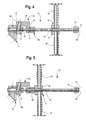
- one operates the device by grasping the handles 80, 82 with his hands and longitudinally moving the hammer 74 from a position against the first nut 68 (as shown in Fig. 5 ) along the length thereof and causing it to impact against the stop 70 (as shown in Fig. 6 ) to thereby disengage the shank 24 of the quick-change holder 12 from the axial bore 22 of the base block mounting 14.
- the quick-change tool holder 12 will remain connected to the end 46 of the elongate member 44 and will not drop so as to cause personal injury or property damage.
- portions of the device 10 may be used to extract a quick-change tool holder 84 from a base block mounting 86 which does not have a plunger therein, or the plunger has been removed.
- the hook arm 50 is unnecessary and is unthreaded from the first end 46 of the elongate member 44.
- the first end of the elongate member 44 is then extended through the axial hole 88 of the quick-change tool holder 84 until a portion thereof extends outward of the rearward end 90 thereof.
- a third threaded nut 92 is fitted on the first end 46 and the quick-change tool holder 84 is then snugly retained between the first and third threaded nuts 68, 92.
- the hammer 74 is moved along the elongate member 44 as described above to strike the stop 76 to force the shank 94 of the quick-change tool holder 84 out of the bore of the base block mounting 86.
- the threads of the elongate member 44 have a flat and wide outer surface so as not to become worn as a result of the movement of the hammer 74.
- the threads are 3 ⁇ 4 - 5 ACME threads.
- the threads in the threaded hole 54 of the hook arm 50 and in the various nuts 68, 70, 92 are female 3 ⁇ 4 - 5 ACME threads.
- a machine used for cutting hard surfaces retains a cutting tool 45 having a cutting portion 96 and extending axially rearward of the cutting portion 96 is a generally cylindrical shank 43.
- the generally cylindrical shank 43 is received within the axial bore 32 of the quick-change tool holder 12 substantially as described above.
- a wear ring 98 Positioned between the forward surface 28 of the quick-change tool holder 12 and a rearwardly facing annular flange of the cutting portion 96 of the cutting tool 45 is a wear ring 98 that protects the forward surface 28 from becoming worn away as a result of rotation of the cutting tool 45 in the axial bore 32.
- the cylindrical shank 43 of the cutting tool 45 is retained within the axial bore 32 by a generally tubular retaining sleeve 100 that engages an annular shoulder (unnumbered) on the shank 43 thereby preventing forward movement of the cutting 45 and also applies a radially outward pressure against the inner surface of the cylindrical axial bore 32 of the quick-change tool holder 12 to retain the cutting tool 45 within the quick-change tool holder 12.
- the receptacle bore 36 of the quick-change tool holder 12 has a diameter that is equal to or a little greater than the axial bore 32, the receptacle bore 36 will receive the shank 43 of a typical cutting tool 45 used by the machine. It should be appreciated that while the quick-change tool holders 12 are infrequently replaced, perhaps twice each working season, the cutting tools 45 are replaced on a more frequent basis, perhaps more than once during each work day. As a result, an operating technician will have access to many worn tools that have fallen to the ground after removal or have been collected in boxes. The operator can readily obtain one of the worn tools and, as shown in Fig.
- a worn tool be used for this purpose because a new tool may become damaged during the extraction process. If for some reason a worn tool is not available, a drive pin of the type used to insert a tool holder into a base block mounting has a shank the outer diameter of which is sized to fit within the bore of the tool holder and can also fit into the transverse hole.
- a disc shaped metal plug 104 is inserted into the hole 36 near the outer surface of the tool holder 12.
- a cylindrical counterbore 58 is provided around the mouth of the hole 54 adjacent the outer surface 50 with the counterbore 105 having a diameter a little larger than the diameter of the receptacle hole 36 so as to form an annular shoulder 106 that is recessed a short distance from the outer surface.
- the counterbore 105 is preferably angled so that the outer surface of the plug 104 will conform as nearly as possible to the adjacent portions of the outer surface of the tool holder 12. The outer circumference of the disc shaped plug 104 rests against the annular shoulder 106.
- the plug 104 is manufactured with concave and convex surfaces 107, 108 respectively opposite each other such that the surfaces of the plug 104 are partially spherical.
- the outer circumference of the plug 104 is made a little smaller than the inner circumference of the counterbore 105 but larger that the inner circumference of the receptacle hole 36 such that the outer edge of the plug 104 will rest upon the shoulder 106 formed by the counterbore 105.
- a tool 110 having a circular substantially planar end surface 112 having a diameter approximately equal to the diameter of the metal plug 104 is pounded against the radially outwardly bowed outer surface 108 of the plug 104 causing the plug 104 to deform and causing the cylindrical outer surface thereof to be compressed against the cylindrical inner surface of the counterbore 105 as shown in Fig. 8 , thereby locking the plug in place.
- the plug 104 has a thickness of about 0.2 cm (0.080 inches) and is carburized about 0.05 cm (0.020 inches) deep and hardened to a hardness of between Rc 55 and Rc 67 on the Rockwell "C" scale of hardness.
- the outer circumference of the plug 104 will then be harder than the metal forming the wall of the counterbore.
- the lower circumference of the plug 104 will be more radially extended and will bite into the wall of the counterbore 105 to retain the plug 104.
- a quick-change tool holder 12 having a sealed receptacle hole 36 Another advantage of a quick-change tool holder 12 having a sealed receptacle hole 36 is that the cavity adjacent the axial bore 32 and underneath the plug 104 becomes a collection box for debris that enters the space between the cutting tool shank 43 and the axial bore 32 allowing better rotation of the cutting tool 45 and thereby increasing tool life.
- a second embodiment of a quick-change tool holder 120 has an enlarged forward end 122, a rearwardly directed generally cylindrical shank 128 and an axial bore 118 extending from a forward surface 124 to a planar rearward end 130.
- a receptacle hole 154 has a longitudinal axis 153 that intersects the longitudinal axis 126 of the tool holder 120.
- Near the outer surface 150 of the tool holder 120 and surrounding the receptacle hole 154 is a cylindrical counterbore 158 into which a plug 156 is fitted.
- the described parts are all similar to that described above with respect to tool holder 12.
- elongate notch 170 that extends into the wall of the counterbore 158 and the wall of the receptacle hole 154.
- the plug 256 can be retained against the annular surface 259 of a counterbore 258 around a receptacle hole 244 by deforming the rim 272 of the counterbore 258 and causing portions of the metal of the tool holder 220 to fold over the outer surface 262 of the plug 256.
- a tool 280 having a generally cylindrical body 282 with a diameter approximately equal to that of the plug 256 is provided.
- the tool 280 has a plurality of parallel ribs extending along the outer surface of the body 282, two of which bearing indicia numbers 284, 285 are visible.
- the lower end of ribs 284, 285 extend at least to the lower end of the tool body 282.
- the lower end of the ribs 284, 285 are positioned against the surface 250 of the tool holder 220 forming the rim 272.
- the opposite end of the tool body 282 is then struck with a hammer, not shown, causing the ribs 284, 285 to deform portions 286, 287, 288, 289 of the rim 272 to lock the plug 256 in place.
Landscapes
- Engineering & Computer Science (AREA)
- Mining & Mineral Resources (AREA)
- Mechanical Engineering (AREA)
- Life Sciences & Earth Sciences (AREA)
- General Life Sciences & Earth Sciences (AREA)
- Geochemistry & Mineralogy (AREA)
- Geology (AREA)
- Percussive Tools And Related Accessories (AREA)
- Drilling Tools (AREA)
Applications Claiming Priority (2)
| Application Number | Priority Date | Filing Date | Title |
|---|---|---|---|
| US11/998,676 US20090142151A1 (en) | 2007-11-30 | 2007-11-30 | Quick-change tool holder |
| US12/193,866 US8069544B2 (en) | 2008-08-19 | 2008-08-19 | Device for extracting a quick-change tool holder |
Publications (1)
| Publication Number | Publication Date |
|---|---|
| EP2065558A2 true EP2065558A2 (de) | 2009-06-03 |
Family
ID=40394061
Family Applications (1)
| Application Number | Title | Priority Date | Filing Date |
|---|---|---|---|
| EP08253839A Withdrawn EP2065558A2 (de) | 2007-11-30 | 2008-11-28 | Vorrichtung zur Extraktion einer Halterung zum schnellen Wechsel eines Werkzeugs |
Country Status (4)
| Country | Link |
|---|---|
| EP (1) | EP2065558A2 (de) |
| AU (1) | AU2008249198A1 (de) |
| CA (1) | CA2644627A1 (de) |
| MX (1) | MX2008014996A (de) |
Cited By (3)
| Publication number | Priority date | Publication date | Assignee | Title |
|---|---|---|---|---|
| KR101022348B1 (ko) | 2009-08-28 | 2011-03-22 | 삼보중공업(주) | 노면 파쇄기용 공구 홀더 장치의 재생방법 |
| CN107508180A (zh) * | 2017-09-18 | 2017-12-22 | 国网福建省电力有限公司 | 断路器机构主轴快速更换工装及更换方法 |
| CN117532301A (zh) * | 2024-01-10 | 2024-02-09 | 太原理工大学 | 一种用于快速连接与拆卸矿用截齿的超声传递装置 |
Citations (1)
| Publication number | Priority date | Publication date | Assignee | Title |
|---|---|---|---|---|
| US6371567B1 (en) | 1999-03-22 | 2002-04-16 | The Sollami Company | Bit holders and bit blocks for road milling, mining and trenching equipment |
-
2008
- 2008-11-24 CA CA002644627A patent/CA2644627A1/en not_active Abandoned
- 2008-11-25 MX MX2008014996A patent/MX2008014996A/es not_active Application Discontinuation
- 2008-11-25 AU AU2008249198A patent/AU2008249198A1/en not_active Abandoned
- 2008-11-28 EP EP08253839A patent/EP2065558A2/de not_active Withdrawn
Patent Citations (2)
| Publication number | Priority date | Publication date | Assignee | Title |
|---|---|---|---|---|
| US6371567B1 (en) | 1999-03-22 | 2002-04-16 | The Sollami Company | Bit holders and bit blocks for road milling, mining and trenching equipment |
| US6585326B2 (en) | 1999-03-22 | 2003-07-01 | The Sollami Company | Bit holders and bit blocks for road milling, mining and trenching equipment |
Cited By (4)
| Publication number | Priority date | Publication date | Assignee | Title |
|---|---|---|---|---|
| KR101022348B1 (ko) | 2009-08-28 | 2011-03-22 | 삼보중공업(주) | 노면 파쇄기용 공구 홀더 장치의 재생방법 |
| CN107508180A (zh) * | 2017-09-18 | 2017-12-22 | 国网福建省电力有限公司 | 断路器机构主轴快速更换工装及更换方法 |
| CN117532301A (zh) * | 2024-01-10 | 2024-02-09 | 太原理工大学 | 一种用于快速连接与拆卸矿用截齿的超声传递装置 |
| CN117532301B (zh) * | 2024-01-10 | 2024-03-22 | 太原理工大学 | 一种用于快速连接与拆卸矿用截齿的超声传递装置 |
Also Published As
| Publication number | Publication date |
|---|---|
| AU2008249198A1 (en) | 2009-06-18 |
| MX2008014996A (es) | 2009-09-03 |
| CA2644627A1 (en) | 2009-05-30 |
Similar Documents
| Publication | Publication Date | Title |
|---|---|---|
| US8069544B2 (en) | Device for extracting a quick-change tool holder | |
| US7891084B1 (en) | Extraction device for removing a quick-change tool holder from a base block mounting | |
| JP3271980B2 (ja) | 壊れたボルト等の抜き取り用工具 | |
| US7152509B2 (en) | Fastener extractor | |
| EP0724505B1 (de) | Werkzeug zum herausziehen von ringförmigen einsätzen | |
| US8601662B1 (en) | Bit puller | |
| WO2012012160A2 (en) | Cutter assembly configured to allow tool rotation | |
| US7185563B2 (en) | Impact driver and fastener removal device | |
| AU2019323774A1 (en) | Fastener extractor device | |
| US4669341A (en) | Extraction device | |
| US5058275A (en) | Chisel | |
| EP2065558A2 (de) | Vorrichtung zur Extraktion einer Halterung zum schnellen Wechsel eines Werkzeugs | |
| US20170173770A1 (en) | Device for extracting cutting bit from holder | |
| JPH09507171A (ja) | 拡張ジョー式の破断ボルト取り除き器 | |
| US4572035A (en) | Tool constructions for removing frozen nuts | |
| US9352459B2 (en) | Broken bolt extractor | |
| US4872231A (en) | Impact blade tool | |
| US11105356B2 (en) | Drop-in anchor setting tool | |
| JP7340865B2 (ja) | 突き刺し具 | |
| US8201893B1 (en) | Quick-change tool holder with transverse hole | |
| US20190076998A1 (en) | Bit driver and method for its use | |
| US8281474B2 (en) | Tool and method of use for extraction of failed wheel bearings | |
| JPH01503128A (ja) | ねじ切り用工具 | |
| US20090142151A1 (en) | Quick-change tool holder | |
| US20090241313A1 (en) | Pin Removal and Insertion Tool |
Legal Events
| Date | Code | Title | Description |
|---|---|---|---|
| PUAI | Public reference made under article 153(3) epc to a published international application that has entered the european phase |
Free format text: ORIGINAL CODE: 0009012 |
|
| AK | Designated contracting states |
Kind code of ref document: A2 Designated state(s): AT BE BG CH CY CZ DE DK EE ES FI FR GB GR HR HU IE IS IT LI LT LU LV MC MT NL NO PL PT RO SE SI SK TR |
|
| AX | Request for extension of the european patent |
Extension state: AL BA MK RS |
|
| STAA | Information on the status of an ep patent application or granted ep patent |
Free format text: STATUS: THE APPLICATION HAS BEEN WITHDRAWN |
|
| 18W | Application withdrawn |
Effective date: 20091110 |