EP2065113A1 - Cutting assembly for an impact cutting device and method for separating a workpiece - Google Patents
Cutting assembly for an impact cutting device and method for separating a workpiece Download PDFInfo
- Publication number
- EP2065113A1 EP2065113A1 EP08020668A EP08020668A EP2065113A1 EP 2065113 A1 EP2065113 A1 EP 2065113A1 EP 08020668 A EP08020668 A EP 08020668A EP 08020668 A EP08020668 A EP 08020668A EP 2065113 A1 EP2065113 A1 EP 2065113A1
- Authority
- EP
- European Patent Office
- Prior art keywords
- workpiece
- support
- separated
- cutting
- arrangement according
- Prior art date
- Legal status (The legal status is an assumption and is not a legal conclusion. Google has not performed a legal analysis and makes no representation as to the accuracy of the status listed.)
- Withdrawn
Links
Images
Classifications
-
- B—PERFORMING OPERATIONS; TRANSPORTING
- B23—MACHINE TOOLS; METAL-WORKING NOT OTHERWISE PROVIDED FOR
- B23D—PLANING; SLOTTING; SHEARING; BROACHING; SAWING; FILING; SCRAPING; LIKE OPERATIONS FOR WORKING METAL BY REMOVING MATERIAL, NOT OTHERWISE PROVIDED FOR
- B23D21/00—Machines or devices for shearing or cutting tubes
- B23D21/14—Machines or devices for shearing or cutting tubes cutting inside the tube
Definitions
- the invention relates to a cutting arrangement for a cutting device, in particular for a percussion cutting device, for cutting, in particular for adiabatic cutting, of workpieces and a method for cutting, in particular for cutting, workpieces thereof.
- a high pulse is transmitted to a moving die, which is laterally displaced by the pulse against a rigid die.
- the workpiece is clamped in a passage through the matrices, the cross section of which corresponds to that of the workpiece to be separated.
- a cutting arrangement on at least two die elements for receiving a workpiece to be separated, in particular for receiving and separating hollow material such as pipes.
- At least one die element is movably mounted with respect to the or the other Matrizenium.
- a support device is arranged, such as a support mandrel, bolt or the like, to support and stabilize a workpiece to be machined in the tool holder.
- the workpiece can be stabilized, for example, by arranging a mandrel inside a tube to be cut in the workpiece holder and supporting the tube from the inside.
- the support device has at least a first and a second support element, which are interconnected by means of a connecting device.
- Workpieces to be cut may be any type of hollow material of any cross-section, e.g. Pipe material with a round, rectangular or an irregular shaped cross-section, but remains the same along the feed direction or in the axial direction of the material.
- the interior of a hollow material can also be subdivided by one or more partition walls, wherein the support device then has a number of elements corresponding to the number of partial interiors in order to respectively stabilize or support the respective interior spaces.
- an angular offset between the two elements may occur. Since the support device is arranged in the tool holder of the die elements can also occur an angular offset between the at least two support elements of the support device, especially if at least one support element is arranged in the movable die element and a contact surface between the support elements in the parting plane. As a result, contaminants can penetrate between the support elements, which would reduce the separation precision after repeated repeats. Since the connecting device connects the individual support elements with each other, in particular connects tightly against each other, arises when moving, or when separating, no or almost no angular offset between the support elements, and thus in particular no gap between the displaced when separating end faces.
- the connecting device is arranged inside or substantially inside the supporting device, in particular in at least one passage or bore of the supporting device.
- the connecting device has at least one tension element, in particular a cable pull, such as a Bowden cable.
- the tension element is under tension to transmit tensile forces when connecting the support elements. Any material with a sufficiently high tensile strength or stability is suitable, e.g. Stole. Also possible is the arrangement of several tension elements, e.g. in order to distribute the tensile forces to be distributed among several elements so that overall the individual elements are less stressed.
- a tension element constantly exerts a nearly constant tensile force on the connecting element, so that the support elements are pressed against each other.
- a gap between the individual support elements can therefore almost not occur or a gap is closed immediately after the occurrence of the tensile force of the compensating element again.
- the connecting device advantageously has a tensioning device for tensioning the tension element.
- a tensioning device for tensioning the tension element.
- a cable may be tensioned by means of a ratchet, the tensioning device advantageously having corresponding fasteners for holding a set tension, e.g. Locknuts or similar.
- the connecting device advantageously has at least one compensating element for compensating the tensile load, such as spiral springs.
- the compensating element simultaneously forms or is the tensioning device, such as a spring which keeps the tension element under tension and at the same time at an expansion of the Tensile element at least so far yields that an overload of the tension element is avoided.
- the tension member is perpendicular or substantially perpendicular to the parting plane of the cutting assembly, i. the tensile force for holding together the support elements is applied perpendicular to the parting plane.
- the support device has at least one passage or passage in which the connection device is arranged. Through the passage, the at least one tension element can be guided, wherein a plurality of passages can also be provided for a plurality of tension elements.
- the number and diameter of the passage or the passages depends on the cross section of the support device. Despite the passages, the supporting device must have a sufficiently high stability in order to withstand a blow when separating without deformation.
- the support device has at least one at least partially beveled end or end region.
- the openings of the support elements in particular openings facing each other, at least partially chamfered to ensure a contact-free course of the one or more tension elements in the respective passage during the displacement or displacement.
- the cutting arrangement has a movable positioning device with which the support device can be positioned in the tool holder.
- the support device By the positioning device, such as a movable carriage, on which a stop such as a rod or mandrel is arranged, the support device can be repeatedly pushed to the exact same location in the tool holders of the die elements. In particular, in a position in which one surface of the support device, eg a contact surface of the support elements or an end surface of the support device, lies in a plane with the parting plane.
- the positioning device is axially or substantially axially movable to the receptacles of the die elements, in particular horizontally movable.
- the positioning device in a percussion cutting machine with vertically extending parting plane and thus horizontal supply of the to be separated Workpiece at least horizontally movable.
- a separate workpiece part from the movable die can be removed or received by means of the positioning device, in particular the separate workpiece part with the positioning of a conveyor can be delivered.
- At least part of the outer circumference of the supporting device rests on an inner circumference of a workpiece to be separated, in particular in the region of the parting plane.
- the pulse transmitted to the workpiece is thereby transmitted directly to the support device.
- the support stabilizes the inner contour or cross-section of the workpiece to be separated, so that it is not or almost not deformed.
- At least one first support element is arranged in the movable die element and an adjoining second support element in the or the other die elements.
- a (front) surface of the first support element, which adjoins a (front) surface of the at least second support element lies in the parting plane of the cutting device. The exact position of the end face (s) in the parting plane is ensured by the positioning of the support device with the positioning device.
- the support device has at least one adaptation or tolerance element.
- an outer periphery of the support device on a tolerance ring, a disc spring or the like This ensures a secure fit of the support device in a workpiece to be separated.
- At least one end portion of the support device is chamfered.
- a damping device is arranged between the side opposite the impact side of the movable die and the support structure.
- the cutting arrangement has a workpiece conveying device for feeding a workpiece, in particular rod material, of a predetermined length into the receptacles of the at least two die elements.
- the workpiece conveying device has a clamping device for temporarily clamping the workpiece to be supplied.
- a method for separating workpieces can be carried out in particular with the cutting arrangement described above.
- the workpiece holder of the cutting assembly becomes a workpiece, such as a workpiece.
- Pipe material supplied.
- the support device With the movable positioning device, the support device is positioned in the workpiece holder so that a surface of the support device is aligned flush with the parting plane of the cutting assembly, i. the area lies in the dividing plane.
- the surface can be an end face of the guide arrangement or, preferably, a contact surface can be in contact with one end face of the first support element with an end face of the at least one second support element.
- the support device abuts at least partially on an inner circumference of the workpiece to be separated, so that the pulse is transmitted directly to the support device during separation.
- a part of the support device may lie flat on the inner circumference or the support device has a profile on the circumference, such. Grooves that support the workpiece sufficiently to prevent or reduce deformation of the workpiece during separation.
- the separated workpiece is ejected or ejected from the workpiece holder, in particular a stop element of the positioning device.
- the movable positioning device can then subsequently be used for transporting the cut workpiece.
- the separated workpiece for example, can also be ejected directly onto a conveyor or into a collecting container.
- the position of the support device in the workpiece holder during further feeding of a workpiece ie the Orientation of the front or contact surface of the support device to the parting plane, is held during or after further feeding the support device again by means of the positioning device in this position or moved into this position.
- the positioning device bears against the supporting device in order to secure the position of the supporting device in the tool holders.
- a feed device for feeding and / or further feeding a workpiece to be separated, at least during the separation of the workpiece to be separated is decoupled.
- at least part of the outer circumference of the supporting device is at least partly located on the inner circumference of the workpiece blank to be separated, at least during the separation, in particular the supporting device abuts adjacent to or near the region of the parting plane.
- the cutting arrangement on a clamping device with which the position of a arranged in the tool holders of the die elements to be machined workpiece is secured.
- the clamping device is arranged so that the movable die element is slightly offset from the one or more other die elements, whereby a workpiece arranged in the tool receptacles of the movable and the at least one further die element is clamped and secured.
- the clamping device can be used advantageously in a cutting arrangement without the described supporting device.
- the movable die element relative to the or the other die elements displaceable, in particular by means of at least one wedge-shaped clamping member of the clamping device.
- a cutting device with the clamping device can be provided as follows: Cutting device for a cutting device for separating workpieces, in particular hollow material or tubular material, with at least two die elements each having a receptacle for receiving a workpiece to be separated, wherein at least one of the die elements relative to is movably mounted on the one or more other Matrizenimplantationn; with a workpiece conveying device for feeding a workpiece, in particular rod material, of a predetermined length into the receptacles of the at least two die elements; and with a clamping device for securing a position of a workpiece arranged and to be separated in the workpiece holders.
- the workpiece conveying device of the cutting device has a clamping device for temporarily clamping the workpiece to be supplied.
- the clamping device acts on the displaceable die and has a tracking device, so that the clamping effect for securing the position of the workpiece to be separated also acts on a displacement of the displaceable die.
- the clamping device acts on the displaceable die and the displaceable die is displaceable by means of a return device against the action of the clamping device in a basic position, in particular in a normal position in which the receptacles of the rigid and movable die are aligned.
- a cutting device with the clamping device can be operated according to the following method: A method for securing a workpiece to be separated in a cutting unit with a movable and a movable die, in particular cutting unit or assembly as described in the claims, wherein the dies each have a receptacle for Have receiving the workpiece to be separated, and the method comprises the following steps: a) advancing the workpiece to be separated, in particular of rod material, by means of a workpiece clamping or clamping the workpiece conveyor; b) securing the workpiece to be separated in the mounts of the matrices by exerting a displacement force between the matrices, wherein the displacement force has at least one component acting perpendicular to the axes of the receptacles and wherein the displacement force can act at least temporarily during the displacement of the workpiece to be separated in particular, the displacement force acts on the displaceable die; c) releasing the gripping or the clamping of the workpiece by the workpiece conveyor;
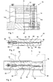
- Fig. 1 shows a side view of a die block 10, which is used in the preferred embodiment of the cutting assembly.
- the die block has a movable die 12 and an adjoining, fixed die 11.
- a blow or pulse on the upper side of the movable die 12 this is moved against the stationary die 11 and arranged in a workpiece holder 14 of the die block 10 workpiece 38, 39 (see. Fig. 3 ) is separated in the cutting or cutting plane A.
- the workpiece holder 14 is subdivided into a first receptacle 14a in the movable matrix 12 and a second receptacle 14b in the rigid matrix 11.
- Fig. 2 shows a preferred embodiment of a support dome 15, which when used in the tool holder 14 of the die block 10 of Fig. 1 is arranged.
- the Guide or support mandrel 15 has two support elements 16, 18, which are connected by means of a connecting device 20-28.
- the connecting device 20-28 has a cable 20 arranged in a passage 34, whose end is fastened to the element 16 with a bolt 26 and whose other end is fastened to the second element 18 on a fastening head 28.
- the passage 34 is divided into a first passage 34a in the movable die and a second passage 34b in the rigid die 11.
- the cable 20 is held under tension by a spring 22 disposed in a recess of the second element 18.
- the two mutually facing ends or end faces of the support elements 16, 18 are pressed together and ensures a connection of the two elements perpendicular to a contact surface 40, wherein a displacement parallel to the contact surface 40 is made possible.
- a beveled end 42 of the support dome 15 of the dome 15 can be easily inserted into the tool holder 14 and in the hollow workpiece. Likewise, an axial displacement in the workpiece 39 is facilitated.
- Fig. 3 shows the support device 15 of Fig. 1 wherein the first element 16 is offset with a cut workpiece 38 after separation against the second element 18.
- the separated workpiece 38 has been separated from the present as rod material workpiece 39 by the separation impact.
- the bar stock is pushed in from the left for the next separation process (cf. Figs 4-7 ).
- the positions of the movable and the fixed die 11, 12 are indicated by dash-dotted lines.
- the openings 30, 32 bevels to (edge) free guidance of the cable 20 from one element to another. In this case, despite the offset between the two support elements 16, 18, the tensile force of the connecting device between the two elements 16, 18 and the same are still pressed together, so that no gap on the contact surface 40 is formed.
- the support mandrel 15 has an adaptation element 36. This ensures that the position of the support dome 15 is secured after insertion into the workpiece.
- This version uses a tolerance ring preloaded with O-rings.
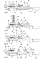
- Figs. 4-7 show stepwise a preferred method for separating workpieces 39 with a cutting assembly in the manner described above with respect to Figs. 1-3 described elements are used.
- Fig. 4 shows a side view of a preferred embodiment of a cutting assembly.
- a positioning device 48 is arranged in addition to the die block 10.
- a stop pin 46 is arranged on a horizontally (direction B) movable carriage 49.
- the workpiece to be separated 39 can be fed by means of a feed gun 44.
- the workpiece 39 is already fed by means of the feed gun 44 by a desired length of the workpiece holder (corresponding to the length of the workpiece to be separated 38).
- the mandrel 15 is positioned in the workpiece holder, that the contact surface 40 of the two support members 16, 18 is located in the parting plane A of the cutting assembly, or the contact surface 40 is aligned with the parting plane 40.
- the position of the support dome 15 in the workpiece holder 14 is secured by the stopper pin 46, which abuts opposite to the feed at one end of the support pin 15.
- Fig. 5 For example, the cutting assembly is shown during or shortly after a beat from the hammer 52 on the movable die 12.
- the movable die 12 By moving the movable die 12 with respect to the rigid die 11 down the workpiece 39 is cut in the parting plane A.
- the pulse or during the execution of the stroke of the stop pin 46 is retracted by a few tenths of a millimeter from the mandrel 15, so that the positioning device 48 is not damaged by shock or impulse transmission. While the stop pin 46 is retracted, the position of the support dome 15 within the workpiece holder 14 or inside the workpiece 39 is secured by the adapter 36.
- the adjustment element 36 ensures that the support mandrel 15 rests against the inner circumference of the workpiece 39 and does not slip and thus in particular the alignment between the contact surface 40 and the parting plane A is maintained.
- the advancing forceps 44 is preferably decoupled from the workpiece to be machined, or no longer grips the workpiece 39, so that the forceps 44 are not damaged by impulse transmission.
- the position of the workpiece 39 with the above-described clamping device 62-70 see FIG. Figs. 8 and 9
- the movable die 12 is slightly offset from the fixed die 11 and thus clamps the workpiece 39 in the position predetermined by the positioning device 48.
- the movable die 12 can easily tilt against the stationary die 11, which in turn can cause a gap in the parting plane A.
- a gap in which contaminants can penetrate can therefore likewise arise between the support elements 16, 18.
- such a gap is immediately closed again by the connecting device, or such a gap only occurs to a lesser extent (for example, size of the gap or frequency) owing to the prestressing of the support elements 16, 18 by the connecting device, or does not occur at all.
- the movable die 12 is returned to its starting position by means of the damping piston 54, so that the workpiece receivers 14a, 14b of the dies 11, 12 are again aligned with one another.
- the stopper mandrel 46 is brought back into contact with the end of the mandrel 15. If the mandrel 15 has been displaced due to the pulse from its position (contact surface 40 is located in parting plane A), the position can be corrected again by means of the positioning device. While the stop pin 46 is applied by means of the feed tong 44 further rod material 39 of the tool holder 14a of the movable die 12 is supplied. By feeding the pipe material by the length of the separate workpiece 38, the cut workpiece 38 is ejected onto the stopper mandrel 46.
- the cut workpiece 38 is shorter than the first support element 16 of the support mandrel 15, or shorter than the receptacle 14a of the movable die 12, the cut workpiece is ejected or pushed onto the stop mandrel 46 only at the next further feeding or subsequent feeding , After ejection of the mounted on a carriage 49 stop mandrel 46 is moved horizontally away from the die block 10. As a result, the workpiece 38 is delivered to a scraper 50.
- the scraper 50 is a block, would also be sufficient individual rods, brushes or the like to strip a lying on the stop pin 46 workpiece.
- the cut workpiece 38 is dropped on a conveyor belt 56 and can be transported to other processing equipment or a collection container (not shown). In this embodiment, on the conveyor belt 56, a switch 58 is arranged, which, e.g. sorted out the first bleed of a rod material or other unusable parts.
- Fig. 7 shows the cutter during stripping.
- the cut workpiece 38 falls onto the conveyor belt 56 and is delivered to further processing steps.
- the feed gun 44 can return to "nachgreif" so that there is sufficient material for feeding during further feeding.
- the position of the already supplied workpiece 39 is secured in the workpiece holder 14 by the clamping device, despite the driven away abutment mandrel 46 of the positioning device 48. With the stop pin 46 of the mandrel 15 is then correctly positioned again and it follows a separation of the workpiece 39 as already described above.
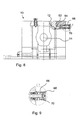
- Fig. 8 shows a front view of the die block 10 of Fig. 1 with a partial section in the region of the clamping device 62-70.
- the clamping device 62-70 has a wedge 62 which is arranged between the die block 10 and the movable die 12.
- the wedge 62 can be withdrawn or pushed further into the die block 10.
- the wedge shape displaces the movable die 12 downwards against the stationary die 11 by a few tenths of a millimeter, so that a workpiece 39 arranged in the workpiece receivers 14a, 14b is clamped.
- the clamping device 62-70 is held by a spring 66 which abuts a head 68 of the clamping device 62-70, even without actuator or in case of failure of the device in a retracted position, so that the movable die 12 can be pushed back into an initial position, in the images 14a, 14b of the matrices 11, 12 are aligned, see also Fig. 9 ,
- the wedge 62 is not fixed rigidly to the bolt 64, but is loosely "suspended". Since the clamping device 62-70 also during or at least until shortly before the separation on the movable die 12 is applied, a momentum transfer to the clamping device 62-70 occur. In addition, when moving the movable die 12 downwards, the clamping device 62-70 or the wedge 62 can slide further into the die block 10, and when the movable die 12 is returned, a shock or pressure on the clamping device 62-70 can likewise occur.
- the wedge 62 Since the wedge 62 is at least partially decoupled from the bolt 64 and the other parts by being loosely suspended, the wedge 62 can at least partially compensate for a shock and keep any impulse transmission or vibration away from the other parts of the clamping device. As a result, these parts of the clamping device are spared and maintenance times are reduced. By hanging in addition, in case of damage to the wedge 62, the wedge 62 can be easily replaced.
Landscapes
- Engineering & Computer Science (AREA)
- Mechanical Engineering (AREA)
- Perforating, Stamping-Out Or Severing By Means Other Than Cutting (AREA)
Abstract
Description
Die Erfindung betrifft eine Schneidanordnung für eine Schneidevorrichtung, insbesondere für eine Schlagschneidevorrichtung, zum Trennen, insbesondere zum adiabatischen Trennen, von Werkstücken und ein Verfahren zum Trennen, insbesondere zum Schneiden, von Werkstücken hierfür.The invention relates to a cutting arrangement for a cutting device, in particular for a percussion cutting device, for cutting, in particular for adiabatic cutting, of workpieces and a method for cutting, in particular for cutting, workpieces thereof.
Beim Hochgeschwindigkeits-Schlagschneiden wird ein hoher Impuls auf eine bewegliche Matrize übertragen, die durch den Impuls lateral gegen eine starre Matrize verschoben wird. Zwischen den Matrizen ist in einem Durchgang durch die Matrizen das Werkstück eingespannt, wobei deren Querschnitt dem des zu trennenden Werkstücks entspricht. Die Beobachtungen zeigen, dass das zu schneidende Werkstück, insbesondere bei Vollmaterial, bei sehr kurz, aber heftig einwirkendem Impuls nahezu ohne plastische Verformung trennbar ist. Dabei wird die verschiebbare Matrize lediglich um wenige zehntel Millimeter gegenüber der starren Matrize versetzt.In high-speed impact cutting, a high pulse is transmitted to a moving die, which is laterally displaced by the pulse against a rigid die. Between the matrices, the workpiece is clamped in a passage through the matrices, the cross section of which corresponds to that of the workpiece to be separated. The observations show that the workpiece to be cut, especially in the case of solid material, can be separated almost without any plastic deformation in the case of a pulse that is very short but violently acting. The displaceable die is only offset by a few tenths of a millimeter from the rigid die.
In der
Es ist Aufgabe der Erfindung, eine Schneidanordnung und ein Verfahren zum Trennen vorzusehen, die beim Schlagschneiden eine hohe Trennpräzision auch bei häufiger Schlagwiederholung gewährleisten.It is an object of the invention to provide a cutting assembly and a method for separating, which ensure a high separation precision even with frequent repeating blow the cutting.
Diese Aufgabe wird mit den Merkmalen des Anspruchs 1 bzw. 13 gelöst. Vorteilhafte Ausgestaltungen sind Gegenstand von Unteransprüchen.This object is achieved with the features of
Gemäß Anspruch 1 weist eine Schneidanordnung zumindest zwei Matrizenelemente zum Aufnehmen eines zu trennenden Werkstücks auf, insbesondere zum Aufnehmen und Trennen von Hohlmaterial wie z.B. Rohren. Zumindest ein Matrizenelement ist bezüglich des oder der anderen Matrizenelemente beweglich gelagert. In der Werkstückaufnahme der Matrizenelemente ist eine Stützvorrichtung angeordnet, wie z.B. ein Stützdorn, -bolzen oder ähnliches, um ein zu bearbeitendes Werkstück in der Werkzeugaufnahme zu stützen und zu stabilisieren. Das Werkstück kann z.B. dadurch stabilisiert werden, dass ein Stützdorn im Inneren eines in der Werkstückaufnahme zu schneidenden Rohres angeordnet ist und das Rohr von Innen stützt. Beim Trennen des Werkstücks wird so durch die Stützvorrichtung verhindert, dass sich der Querschnitt des Werkstücks beim Trennvorgang verformt. Die Stützvorrichtung weist dabei zumindest ein erstes und ein zweites Stützelement auf, die mittels einer Verbindungseinrichtung miteinander verbunden sind.According to
Zu trennende Werkstücke können jede Art von Hohlmaterial mit beliebigem Querschnitt sein, wie z.B. Rohrmaterial mit rundem, rechteckigen oder einem unregelmäßig geformten Querschnitt, der jedoch entlang der Zufuhrrichtung bzw. in axialer Richtung des Materials gleich bleibt. Zum Beispiel kann auch der Innenraum eines Hohlmaterials durch ein oder mehrere Trennwände unterteilt sein wobei die Stützvorrichtung dann eine der Anzahl der Teil-Innenräume entsprechende Anzahl an Elementen aufweist, um die jeweiligen Innenräume entsprechend zu stabilisieren bzw. zu stützen.Workpieces to be cut may be any type of hollow material of any cross-section, e.g. Pipe material with a round, rectangular or an irregular shaped cross-section, but remains the same along the feed direction or in the axial direction of the material. For example, the interior of a hollow material can also be subdivided by one or more partition walls, wherein the support device then has a number of elements corresponding to the number of partial interiors in order to respectively stabilize or support the respective interior spaces.
Beim Verschieben des beweglichen Matrizenelements gegen ein angrenzendes Matrizenelement kann ein Winkelversatz zwischen den beiden Elementen auftreten. Da die Stützvorrichtung in der Werkzeugaufnahme der Matrizenelemente angeordnet ist kann ebenso ein Winkelversatz zwischen den zumindest zwei Stützelementen der Stützvorrichtung auftreten, insbesondere wenn zumindest ein Stützelement im beweglichen Matrizenelement angeordnet ist und eine Kontaktfläche zwischen den Stützelementen in der Trennebene liegt. Dadurch können Verunreinigungen zwischen die Stützelemente eindringen, wodurch sich nach häufiger Schlagwiederholung die Trennpräzision verringern würde. Da die Verbindungseinrichtung die einzelnen Stützelemente miteinander verbindet, insbesondere dicht aneinander anliegend verbindet, entsteht beim Verschieben, bzw. beim Trennen, kein oder nahezu kein Winkelversatz zwischen den Stützelementen und damit insbesondere kein Spalt zwischen den beim Trennen zueinander verschobenen Stirnflächen. Das bedeutet, dass nahezu keine Verunreinigungen zwischen die Stützelemente eindringen können, woraus sich ein geringerer Verschleiß der Stützelemente, insbesondere von gegeneinander bewegten Kontaktflächen der Stützelemente ergibt. Durch Verwendung der Verbindungseinrichtung ergibt sich demnach eine hohe Trennpräzision und ebenso eine hohe Standzeit der Schneidanordnung auch nach häufiger Schlagwiederholung.When moving the movable die element against an adjacent die element, an angular offset between the two elements may occur. Since the support device is arranged in the tool holder of the die elements can also occur an angular offset between the at least two support elements of the support device, especially if at least one support element is arranged in the movable die element and a contact surface between the support elements in the parting plane. As a result, contaminants can penetrate between the support elements, which would reduce the separation precision after repeated repeats. Since the connecting device connects the individual support elements with each other, in particular connects tightly against each other, arises when moving, or when separating, no or almost no angular offset between the support elements, and thus in particular no gap between the displaced when separating end faces. This means that almost no contamination can penetrate between the support elements, resulting in a lower wear of the support elements, in particular of mutually moving contact surfaces of the support elements. By using the Connecting device thus results in a high separation precision and also a long service life of the cutting assembly even after repeated repeating beat.
Bei einer Ausgestaltung ist die Verbindungseinrichtung innerhalb oder im Wesentlichen innerhalb der Stützvorrichtung angeordnet, insbesondere in zumindest einem Durchgang oder Bohrung der Stützvorrichtung.In one embodiment, the connecting device is arranged inside or substantially inside the supporting device, in particular in at least one passage or bore of the supporting device.
Vorteilhaft weist die Verbindungseinrichtung zumindest ein Zugelement auf, insbesondere ein Seilzug, wie ein Bowdenzug. Vorteilhaft steht das Zugelement unter Zugspannung, um Zugkräfte beim Verbinden der Stützelemente zu übertragen. Jedes Material mit einer genügend hohen Reißfestigkeit bzw. Stabilität ist dazu geeignet, z.B. Stahl. Ebenfalls möglich ist die Anordnung von mehreren Zugelementen, z.B. um die auszuübenden Zugkräfte auf mehrere Elemente zu verteilen, damit insgesamt die einzelnen Elemente weniger stark beansprucht werden.Advantageously, the connecting device has at least one tension element, in particular a cable pull, such as a Bowden cable. Advantageously, the tension element is under tension to transmit tensile forces when connecting the support elements. Any material with a sufficiently high tensile strength or stability is suitable, e.g. Stole. Also possible is the arrangement of several tension elements, e.g. in order to distribute the tensile forces to be distributed among several elements so that overall the individual elements are less stressed.
Ganz besonders vorteilhaft übt ein Zugelement ständig eine nahezu konstante Zugkraft auf das Verbindungselement aus, so dass die Stützelemente aneinander gepresst werden. Ein Spalt zwischen den einzelnen Stützelementen kann daher nahezu nicht auftreten oder ein Spalt wird sofort nach dem Auftreten durch die Zugkraft des Ausgleichselements wieder geschlossen.Very particularly advantageous, a tension element constantly exerts a nearly constant tensile force on the connecting element, so that the support elements are pressed against each other. A gap between the individual support elements can therefore almost not occur or a gap is closed immediately after the occurrence of the tensile force of the compensating element again.
Die Verbindungseinrichtung weist vorteilhaft eine Spanneinrichtung zum Spannen des Zugelements auf. Zum Beispiel kann ein Seilzug mit Hilfe einer Ratsche unter Zugspannung gesetzt werden, wobei die Spanneinrichtung vorteilhaft entsprechende Befestigungen zum Halten einer eingestellten Spannung aufweist, wie z.B. Kontermuttern oder ähnliches.The connecting device advantageously has a tensioning device for tensioning the tension element. For example, a cable may be tensioned by means of a ratchet, the tensioning device advantageously having corresponding fasteners for holding a set tension, e.g. Locknuts or similar.
Beim Verschieben der Stützelemente gegeneinander entsteht eine Zugbelastung auf das Zugelement, da das Zugelement durch das Verschieben gedehnt wird. Um eine Überbelastung des Zugelements zu vermeiden, weist die Verbindungseinrichtung vorteilhaft zumindest ein Ausgleichselement zum Ausgleichen der Zugbelastung auf, wie z.B. Spiralfedern. Durch die Vermeidung von Überlastung des Zugelements wird die Lebensdauer des Zugelements und damit der Stütz- bzw. Schneidanordnung erhöht und Wartungszeiten verringern sich. Besonders vorteilhaft bildet oder ist das Ausgleichselement gleichzeitig die Spanneinrichtung, wie z.B. eine Feder, die das Zugelement unter Zugspannung hält und gleichzeitig bei einer Dehnung des Zugelements zumindest soweit nachgibt, dass eine Überlastung des Zugelements vermieden wird.When moving the support elements against each other creates a tensile load on the tension element, since the tension element is stretched by the displacement. In order to avoid overloading of the tension element, the connecting device advantageously has at least one compensating element for compensating the tensile load, such as spiral springs. By avoiding overloading of the tension element, the service life of the tension element and thus of the support or cutting arrangement is increased and maintenance times are reduced. Particularly advantageously, the compensating element simultaneously forms or is the tensioning device, such as a spring which keeps the tension element under tension and at the same time at an expansion of the Tensile element at least so far yields that an overload of the tension element is avoided.
Besonders vorteilhaft verläuft das Zugelement senkrecht oder im Wesentlichen senkrecht zur Trennebene der Schneidanordnung, d.h. die Zugkraft zum Zusammenhalten der Stützelemente wird senkrecht zur Trennebene ausgeübt.Particularly advantageously, the tension member is perpendicular or substantially perpendicular to the parting plane of the cutting assembly, i. the tensile force for holding together the support elements is applied perpendicular to the parting plane.
Vorteilhaft weist die Stützvorrichtung zumindest einen Durchlass bzw. Durchgang auf in dem die Verbindungseinrichtung angeordnet ist. Durch den Durchlass kann das zumindest eine Zugelement geführt werden, wobei ebenso mehrere Durchlässe für mehrere Zugelemente vorgesehen sein können. Die Anzahl und der Durchmesser des Durchlasses oder der Durchlässe ist abhängig vom Querschnitt der Stützvorrichtung. Die Stützvorrichtung muss trotz der Durchlässe eine genügend hohe Stabilität aufweisen, um einem Schlag beim Trennen ohne Verformung standzuhalten.Advantageously, the support device has at least one passage or passage in which the connection device is arranged. Through the passage, the at least one tension element can be guided, wherein a plurality of passages can also be provided for a plurality of tension elements. The number and diameter of the passage or the passages depends on the cross section of the support device. Despite the passages, the supporting device must have a sufficiently high stability in order to withstand a blow when separating without deformation.
Vorteilhaft weist die Stützvorrichtung zumindest einen zumindest teilweise gefasten End- oder Stirnbereich auf. Beim Verschieben der Stützelemente gegeneinander wird bzw. werden ebenfalls der Durchlass oder die Durchlässe gegeneinander verschoben. Die im Durchlass liegenden Zugelemente können dadurch an den Kanten einer Öffnung der jeweiligen Stützelemente anliegen und evtl. beschädigt werden. Daher sind vorteilhaft die Öffnungen der Stützelemente, insbesondere einander zugewandte Öffnungen, zumindest teilweise gefast, um einen kontaktfreien Verlauf des oder der Zugelemente im jeweiligen Durchlass auch während der Verschiebens oder Versetzens zu gewährleisten.
Besonders vorteilhaft weist die Schneidanordnung eine verfahrbare Positioniervorrichtung auf, mit der die Stützvorrichtung in der Werkzeugaufnahme positionierbar ist. Durch die Positioniervorrichtung, wie z.B. einen verfahrbaren Schlitten, auf dem ein Anschlag wie ein Stab oder Dorn angeordnet ist, kann die Stützvorrichtung immer wieder an die exakt gleiche Stelle in den Werkzeugaufnahmen der Matrizenelemente geschoben werden. Insbesondere in eine Stellung in der eine Fläche der Stützvorrichtung, z.B. eine Kontaktfläche der Stützelemente oder eine Endfläche der Stützvorrichtung, in einer Ebene mit der Trennebene liegt.Advantageously, the support device has at least one at least partially beveled end or end region. When moving the support elements against each other is also or the passage or the passages are shifted from each other. The lying in the traction elements can thereby rest against the edges of an opening of the respective support elements and possibly damaged. Therefore, advantageously, the openings of the support elements, in particular openings facing each other, at least partially chamfered to ensure a contact-free course of the one or more tension elements in the respective passage during the displacement or displacement.
Particularly advantageously, the cutting arrangement has a movable positioning device with which the support device can be positioned in the tool holder. By the positioning device, such as a movable carriage, on which a stop such as a rod or mandrel is arranged, the support device can be repeatedly pushed to the exact same location in the tool holders of the die elements. In particular, in a position in which one surface of the support device, eg a contact surface of the support elements or an end surface of the support device, lies in a plane with the parting plane.
Vorteilhaft ist die Positioniervorrichtung axial oder im Wesentlichen axial zu den Aufnahmen der Matrizenelemente verfahrbar ist, insbesondere horizontal verfahrbar ist. Insbesondere ist die Positioniervorrichtung bei einer Schlagschneidemaschine mit vertikal verlaufender Trennebene und damit horizontaler Zufuhr des zu trennenden Werkstücks zumindest horizontal verfahrbar. Um Werkstücke unter verschiedenen Winkeln zu Schneiden, bzw. Anzuschneiden, ist auch eine Zufuhr des Werkstücks unter verschiedenen Winkeln zur Trennebene möglich. Bei einer Ausgestaltung ist mittels der Positioniervorrichtung ein getrenntes Werkstückteil aus der beweglichen Matrize entnehmbar oder aufnehmbar, insbesondere ist das getrennte Werkstückteil mit der Positioniervorrichtung einer Fördereinrichtung zustellbar.Advantageously, the positioning device is axially or substantially axially movable to the receptacles of the die elements, in particular horizontally movable. In particular, the positioning device in a percussion cutting machine with vertically extending parting plane and thus horizontal supply of the to be separated Workpiece at least horizontally movable. In order to cut or cut workpieces at different angles, it is also possible to feed the workpiece at different angles to the parting plane. In one embodiment, a separate workpiece part from the movable die can be removed or received by means of the positioning device, in particular the separate workpiece part with the positioning of a conveyor can be delivered.
Vorteilhaft liegt zumindest ein Teil des Außenumfangs der Stützvorrichtung an einem Innenumfang eines zu trennenden Werkstücks an, insbesondere im Bereich der Trennebene. Beim Trennen wird dadurch der auf das Werkstück übertragene Impuls direkt weiter auf die Stützvorrichtung übertragen. Die Stützvorrichtung stabilisiert die Innenkontur bzw. -querschnitt des zu trennenden Werkstücks, so dass dieses nicht oder nahezu nicht verformt wird.Advantageously, at least part of the outer circumference of the supporting device rests on an inner circumference of a workpiece to be separated, in particular in the region of the parting plane. During separation, the pulse transmitted to the workpiece is thereby transmitted directly to the support device. The support stabilizes the inner contour or cross-section of the workpiece to be separated, so that it is not or almost not deformed.
Besonders vorteilhaft ist zumindest ein erstes Stützelement im beweglichen Matrizenelement angeordnet und ein daran anschließendes zweites Stützelement in dem oder den anderen Matrizenelementen. Vorteilhaft liegt dabei eine (Stirn-)Fläche des ersten Stützelements, die an eine (Stirn-)Fläche des zumindest zweiten Stützelements anschließt, in der Trennebene der Schneidvorrichtung. Die exakte Position der Stirnfläche(n) in der Trennebene wird durch das Positionieren der Stützvorrichtung mit der Positioniervorrichtung gewährleistet.Particularly advantageously, at least one first support element is arranged in the movable die element and an adjoining second support element in the or the other die elements. Advantageously, a (front) surface of the first support element, which adjoins a (front) surface of the at least second support element, lies in the parting plane of the cutting device. The exact position of the end face (s) in the parting plane is ensured by the positioning of the support device with the positioning device.
Zum Ausgleichen von Toleranzen eines zu trennenden Werkstücks, insbesondere von Toleranzen des Innendurchmessers, weist die Stützvorrichtung zumindest ein Anpassungs- bzw. Toleranzelement auf. Beispielsweise weist ein Außenumfang der Stützvorrichtung einen Toleranzring, eine Scheibenfeder oder ähnliches auf. Damit wird ein sicherer Sitz der Stützvorrichtung in einem zu trennenden Werkstück gewährleistet.To compensate for tolerances of a workpiece to be separated, in particular tolerances of the inner diameter, the support device has at least one adaptation or tolerance element. For example, an outer periphery of the support device on a tolerance ring, a disc spring or the like. This ensures a secure fit of the support device in a workpiece to be separated.
Zum leichteren Einführen der Stützvorrichtung in die Werkstückaufnahme bzw. in ein zu trennendes Werkstück ist zumindest ein Endbereich der Stützvorrichtung gefast.For easier insertion of the support device in the workpiece holder or in a workpiece to be separated at least one end portion of the support device is chamfered.
Besonders vorteilhaft ist zwischen dem beweglichen Matrizenelement und einer Stützstruktur für die Schneidanordnung eine Dämpfungseinrichtung zwischen der der Schlagseite der beweglichen Matrize gegenüberliegenden Seite und der Stützstruktur angeordnet. Mit dem Dämpfungselement wird überschüssige Energie vom Schlag gedämpft, falls die Schlagenergie nicht vollständig in Trennenergie und Wärmeenergie überführt werden konnte. Somit wird die Ausbreitung überschüssiger Schlagenergie, die gerade bei toleranzbehafteten Werkstücken von Schlag zu Schlag stark variieren kann, auf einen möglichst kleinen Teilbereich des Trennwerkzeugs begrenzt und eine Ausbreitung auf die Schneidanordnung weitgehend verhindert.Particularly advantageously, between the movable die element and a support structure for the cutting assembly, a damping device is arranged between the side opposite the impact side of the movable die and the support structure. With the damping element excess energy is damped by the impact, if the impact energy could not be completely converted into separation energy and heat energy. Thus, the spread of excess impact energy, the especially with toleranced workpieces can vary greatly from beat to beat, limited to the smallest possible portion of the cutting tool and largely prevents propagation to the cutting assembly.
Vorteilhaft weist die Schneidanordnung eine Werkstückfördereinrichtung zum Zuführen eines Werkstücks, insbesondere von Stangenmaterial, einer vorgegebenen Länge in die Aufnahmen der zumindest zwei Matrizenelemente auf. In Ausgestaltung weist die Werkstückfördereinrichtung eine Spanneinrichtung zum zeitweisen Spannen des zuzuführenden Werkstücks auf.Advantageously, the cutting arrangement has a workpiece conveying device for feeding a workpiece, in particular rod material, of a predetermined length into the receptacles of the at least two die elements. In an embodiment, the workpiece conveying device has a clamping device for temporarily clamping the workpiece to be supplied.
Ein Verfahren zum Trennen von Werkstücken kann insbesondere mit der oben beschriebenen Schneidanordnung durchgeführt werden. In einem ersten Schritt wird der Werkstückaufnahme der Schneidanordnung ein Werkstück, wie z.B. Rohrmaterial, zugeführt. Mit der verfahrbaren Positioniereinrichtung wird die Stützvorrichtung in der Werkstückaufnahme so positioniert, dass eine Fläche der Stützvorrichtung bündig mit der Trennebene der Schneidanordnung ausgerichtet ist, d.h. die Fläche liegt in der Trennebene. Die Fläche kann eine Stirnfläche der Führungsanordnung sein oder bevorzugt eine Kontaktfläche über die eine Stirnfläche des ersten Stützelements mit einer Stirnfläche des zumindest einen zweiten Stützelements miteinander in Kontakt stehen. Damit wird gewährleistet, dass ein Werkstück beim anschließenden Trennen direkt an der Trennkante unterstützt wird und sich durch den hohen Impuls beim Trennen nicht oder kaum verformt. Bevorzugt liegt während des Trennens die Stützvorrichtung zumindest teilweise an einem Innenumfang des zu trennenden Werkstücks an, damit der Impuls beim Trennen direkt auf die Stützvorrichtung übertragen wird. Dabei kann ein Teil der Stützvorrichtung plan am Innenumfang anliegen oder die Stützvorrichtung weist am Umfang ein Profil auf, wie z.B. Rillen, die das Werkstück ausreichend stützen, um eine Verformung des Werkstücks beim Trennen zu verhindern bzw. zu verringern.A method for separating workpieces can be carried out in particular with the cutting arrangement described above. In a first step, the workpiece holder of the cutting assembly becomes a workpiece, such as a workpiece. Pipe material supplied. With the movable positioning device, the support device is positioned in the workpiece holder so that a surface of the support device is aligned flush with the parting plane of the cutting assembly, i. the area lies in the dividing plane. The surface can be an end face of the guide arrangement or, preferably, a contact surface can be in contact with one end face of the first support element with an end face of the at least one second support element. This ensures that a workpiece is supported during the subsequent separation directly at the separating edge and does not deform or hardly deforms due to the high momentum during separation. Preferably, during the separation, the support device abuts at least partially on an inner circumference of the workpiece to be separated, so that the pulse is transmitted directly to the support device during separation. In this case, a part of the support device may lie flat on the inner circumference or the support device has a profile on the circumference, such. Grooves that support the workpiece sufficiently to prevent or reduce deformation of the workpiece during separation.
Bevorzugt wird nach dem Trennen eines Werkstücks durch das weitere Zuführen eines zu trennenden Werkstücks das abgetrennte Werkstück aus der Werkstückaufnahme ausgeworfen bzw. ausgeschoben, insbesondere auf ein Anschlagelement der Positioniervorrichtung. Die verfahrbare Positioniervorrichtung kann dann anschließend zum Transportieren des geschnittenen Werkstücks verwendet werden. Jedoch kann das abgetrennte Werkstück z.B. auch direkt auf eine Fördereinrichtung oder in einen Sammelbehälter ausgeworfen werden. Um beim weiteren Zuführen eines Werkstücks die Position der Stützvorrichtung in der Werkstückaufnahme zu sichern, d.h. die Ausrichtung der Stirn- oder Kontakt-Fläche der Stützvorrichtung zur Trennebene, wird während oder nach dem weiteren Zuführen die Stützvorrichtung wieder mittels der Positioniervorrichtung in dieser Position gehalten oder in diese Position verschoben. So wird bei jedem Trennvorgang gewährleistet, dass die Stirn- oder Kontakt-Fläche der Stützvorrichtung genau mit der Trennebene ausgerichtet ist und beim Trennen kaum Verschleiß an der oder den Flächen der Stützvorrichtung auftritt. Daher bleibt die Präzision beim Trennen auch nach häufiger Schlagwiederholung konstant hoch und Wartungszeiten verringern sich.Preferably, after the separation of a workpiece by the further feeding of a workpiece to be separated, the separated workpiece is ejected or ejected from the workpiece holder, in particular a stop element of the positioning device. The movable positioning device can then subsequently be used for transporting the cut workpiece. However, the separated workpiece, for example, can also be ejected directly onto a conveyor or into a collecting container. In order to secure the position of the support device in the workpiece holder during further feeding of a workpiece, ie the Orientation of the front or contact surface of the support device to the parting plane, is held during or after further feeding the support device again by means of the positioning device in this position or moved into this position. Thus, it is ensured in each separation process that the front or contact surface of the support device is aligned exactly with the parting plane and when separating hardly any wear occurs on the or the surfaces of the support device. Therefore, the precision of separation remains constant even after repeated repeats and maintenance times are reduced.
Vorteilhaft liegt während des Zuführens und/oder des weiteren Zuführens des zu trennenden Werkstückrohlings die Positioniervorrichtung an der Stützvorrichtung anliegt, um die Position der Stützvorrichtung in den Werkzeugaufnahmen zu sichern. Bei einer alternativen oder zusätzlichen Ausgestaltung ist eine Vorschubvorrichtung zum Zuführen und/oder weiteren Zuführen eines zu trennenden Werkstücks zumindest während des Trennens von dem zu trennenden Werkstück entkoppelt. In weiterer oder alternativer Ausgestaltung liegt zumindest während des Trennens zumindest ein Teil des Außenumfangs der Stützvorrichtung zumindest teilweise am Innenumfang des zu trennenden Werkstückrohlings an, insbesondere liegt die Stützvorrichtung angrenzend an oder nahe des Bereichs der Trennebene an.Advantageously, during the feeding and / or the further feeding of the workpiece blank to be separated, the positioning device bears against the supporting device in order to secure the position of the supporting device in the tool holders. In an alternative or additional embodiment, a feed device for feeding and / or further feeding a workpiece to be separated, at least during the separation of the workpiece to be separated is decoupled. In a further or alternative refinement, at least part of the outer circumference of the supporting device is at least partly located on the inner circumference of the workpiece blank to be separated, at least during the separation, in particular the supporting device abuts adjacent to or near the region of the parting plane.
Vorteilhaft weist die Schneidanordnung eine Klemmvorrichtung auf, mit der die Position eines in den Werkzeugaufnahmen der Matrizenelemente angeordneten zu bearbeitenden Werkstücks gesichert wird. So wird insbesondere gewährleistet, dass nach dem Zuführen eines zu trennenden Werkstücks, das Werkstück vor und während dem Trennen seine Position beibehält und nicht verrutscht. Die Präzision bei der Bearbeitung wird dadurch weiter erhöht. Die Klemmvorrichtung ist dabei so angeordnet, dass das bewegliche Matrizenelement gegenüber dem oder den anderen Matrizenelementen leicht versetzt wird, wodurch ein in den Werkzeugaufnahmen des beweglichen und des zumindest einen weiteren Matrizenelements angeordnetes Werkstück eingeklemmt und gesichert wird. Die Klemmvorrichtung kann vorteilhaft in einer Schneidanordnung ohne die beschriebene Stützvorrichtung verwendet werden.Advantageously, the cutting arrangement on a clamping device, with which the position of a arranged in the tool holders of the die elements to be machined workpiece is secured. This ensures in particular that after feeding a workpiece to be separated, the workpiece maintains its position and does not slip before and during the separation. The precision in the processing is thereby further increased. The clamping device is arranged so that the movable die element is slightly offset from the one or more other die elements, whereby a workpiece arranged in the tool receptacles of the movable and the at least one further die element is clamped and secured. The clamping device can be used advantageously in a cutting arrangement without the described supporting device.
Vorzugsweise ist mittels der Klemmvorrichtung das bewegliche Matrizenelement gegenüber dem oder den anderen Matrizenelementen versetzbar, insbesondere mittels zumindest eines keilförmigen Klemmelements der Klemmvorrichtung.Preferably, by means of the clamping device, the movable die element relative to the or the other die elements displaceable, in particular by means of at least one wedge-shaped clamping member of the clamping device.
Dabei kann eine Schneideinrichtung mit der Klemmvorrichtung wie folgt vorgesehen sein: Schneideinrichtung für eine Schneidevorrichtung zum Trennen von Werkstücken, insbesondere von Hohlmaterial oder rohrförmigem Material, mit zumindest zwei Matrizenelementen mit jeweils einer Aufnahme zum Aufnehmen eines zu trennenden Werkstücks, wobei zumindest eines der Matrizenelemente relativ zu dem oder den anderen Matrizenelementen beweglich gelagert ist; mit einer Werkstückfördereinrichtung zum Zuführen eines Werkstücks, insbesondere von Stangenmaterial, einer vorgegebenen Länge in die Aufnahmen der zumindest zwei Matrizenelemente; und mit einer Klemmvorrichtung zum Sichern einer Position eines in den Werkstückaufnahmen angeordneten und zu trennenden Werkstücks.
In einer Ausgestaltung weist die Werkstückfördereinrichtung der Schneideinrichtung eine Spanneinrichtung zum zeitweisen Spannen des zuzuführenden Werkstücks auf. In weiterer zusätzlicher oder alternativer Ausgestaltung wirkt die Klemmvorrichtung auf die verschiebbare Matrize und weist eine Nachführeinrichtung auf, so dass die Klemmwirkung zum Sichern der Position des zu trennenden Werkstücks auch bei einer Verschiebung der verschiebbaren Matrize wirkt. In weiterer alternativer oder zusätzlicher Ausgestaltung wirkt die Klemmvorrichtung auf die verschiebbare Matrize wirkt und die verschiebbare Matrize ist mittels einer Rückstelleinrichtung entgegen der Wirkung der Klemmvorrichtung in eine Grundstellung überführbar, insbesondere in eine Grundstellung, bei der die Aufnahmen der starren und beweglichen Matrize zueinander ausgerichtet sind.In this case, a cutting device with the clamping device can be provided as follows: Cutting device for a cutting device for separating workpieces, in particular hollow material or tubular material, with at least two die elements each having a receptacle for receiving a workpiece to be separated, wherein at least one of the die elements relative to is movably mounted on the one or more other Matrizenelementen; with a workpiece conveying device for feeding a workpiece, in particular rod material, of a predetermined length into the receptacles of the at least two die elements; and with a clamping device for securing a position of a workpiece arranged and to be separated in the workpiece holders.
In one embodiment, the workpiece conveying device of the cutting device has a clamping device for temporarily clamping the workpiece to be supplied. In a further additional or alternative embodiment, the clamping device acts on the displaceable die and has a tracking device, so that the clamping effect for securing the position of the workpiece to be separated also acts on a displacement of the displaceable die. In a further alternative or additional embodiment, the clamping device acts on the displaceable die and the displaceable die is displaceable by means of a return device against the action of the clamping device in a basic position, in particular in a normal position in which the receptacles of the rigid and movable die are aligned.
Dabei kann eine Schneideinrichtung mit der Klemmvorrichtung nach dem folgenden Verfahren betrieben werden: Verfahren zum Sichern eines zu trennenden Werkstücks in einer Schneideeinheit mit einer verschiebbaren und einer beweglichen Matrize, insbesondere Schneideeinheit oder -anordnung wie in den Ansprüche beschrieben, wobei die Matrizen jeweils eine Aufnahme zum Aufnehmen des zu trennenden Werkstücks aufweisen, und das Verfahren die folgenden Schritte aufweist: a) Vorschieben des zu trennenden Werkstücks, insbesondere von Stangematerial, mittels einer das Werkstück greifenden oder klemmenden Werkstück-Fördereinrichtung; b) Sichern des zu trennenden Werkstücks in den Aufnahmen der Matrizen durch Ausüben einer Verschiebungskraft zwischen den Matrizen, wobei die Verschiebungskraft zumindest eine senkrecht zu den Achsen der Aufnahmen wirkende Komponente aufweist und wobei die Verschiebungskraft zumindest zeitweise auch während des Verschiebens des zu trennenden Werkstücks wirken kann, wobei insbesondere die Verschiebungskraft auf die verschiebbare Matrize wirkt; c) Lösen des Greifens oder der Klemmung des Werkstücks durch die Werkstück-Fördereinrichtung; d) Trennen des gesicherten Werkstücks durch Versetzen der verschiebbaren Matrize; e) Rückstellen der verschiebbaren Matrize unter Ausrichtung der Aufnahmen der Matrizen; und f) Wiederholen der obigen Schritte. Gemäß einer Ausgestaltung wirkt eine Rückstelleinrichtung zum Rückstellen der verschiebbaren Matrize zumindest während des Trennens nicht auf die verschiebbare Matrize, insbesondere ist die Rückstelleinrichtung von der verschiebbaren Matrize beabstandet.In this case, a cutting device with the clamping device can be operated according to the following method: A method for securing a workpiece to be separated in a cutting unit with a movable and a movable die, in particular cutting unit or assembly as described in the claims, wherein the dies each have a receptacle for Have receiving the workpiece to be separated, and the method comprises the following steps: a) advancing the workpiece to be separated, in particular of rod material, by means of a workpiece clamping or clamping the workpiece conveyor; b) securing the workpiece to be separated in the mounts of the matrices by exerting a displacement force between the matrices, wherein the displacement force has at least one component acting perpendicular to the axes of the receptacles and wherein the displacement force can act at least temporarily during the displacement of the workpiece to be separated in particular, the displacement force acts on the displaceable die; c) releasing the gripping or the clamping of the workpiece by the workpiece conveyor; d) disconnecting the secured workpiece by moving the movable die; e) resetting the displaceable matrix while aligning the receptacles of the matrices; and f) repeating the above steps. According to one embodiment, a return device for returning the displaceable die does not act on the displaceable die at least during the separation, in particular the return device is spaced from the displaceable die.
Anhand von Zeichnungen werden Ausführungsformen der Erfindung näher erläutert. Es zeigen:
- Fig. 1
- eine Seitenansicht eines Matrizenblocks ohne Stützvorrichtung im Schnitt,
- Fig. 2
- eine Seitenansicht einer Stützvorrichtung im Schnitt,
- Fig. 3
- eine Schnittdarstellung der Seitenansicht der Stützvorrichtung von
Fig. 2 mit gegeneinander verschobenen Stützelementen, - Fig. 4-7
- schrittweise Darstellungen eines Verfahrensablaufs zum Trennen von Werkstücken,
- Fig. 8
- eine Vorderansicht des Matrizenblocks von
Fig. 1 mit einer Darstellung einer Klemmvorrichtung im Schnitt, und - Fig. 9
- ein Detail der Klemmvorrichtung von
Fig. 8 .
- Fig. 1
- a side view of a die block without support device in section,
- Fig. 2
- a side view of a support device in section,
- Fig. 3
- a sectional view of the side view of the support device of
Fig. 2 with mutually displaced support elements, - Fig. 4-7
- step-by-step illustrations of a procedure for separating workpieces,
- Fig. 8
- a front view of the matrix block of
Fig. 1 with an illustration of a clamping device in section, and - Fig. 9
- a detail of the clamping device of
Fig. 8 ,
Zum Ausgleichen von Toleranzen des Innenumfangs bzw. -durchmessers des zu trennenden Werkstücks 39 weist der Stützdorn 15 ein Anpassungselement 36 auf. Dadurch wird gewährleistet, dass die Position des Stützdoms 15 nach dem Einführen im Werkstück gesichert ist. In dieser Ausführung wird ein Toleranzring verwendet, der mit O-Ringen vorgespannt ist.To compensate for tolerances of the inner circumference or diameter of the
Die
In
Während des Verschiebens bzw. der Impulsübertragung kann aufgrund der hohen wirkenden Kräfte die beweglichen Matrize 12 gegen die feststehende Matrize 11 leicht verkippen, wodurch wiederum ein Spalt in der Trennebene A entstehen kann. Ein Spalt, in den Verunreinigungen eindringen können, kann daher ebenfalls zwischen den Stützelementen 16, 18 entstehen. Durch die Verbindungseinrichtung wird jedoch ein solcher Spalt sofort wieder geschlossen, bzw. ein solcher Spalt tritt aufgrund der Vorspannung der Stützelemente 16, 18 durch die Verbindungseinrichtung nur in geringerem Umfang auf (z.B. Größe des Spalts oder Häufigkeit) oder tritt gar nicht auf.During the displacement or the impulse transmission, due to the high forces, the
Nach dem Impuls bzw. dem Trennen wird die bewegliche Matrize 12 mittels des Dämpfungskolbens 54 wieder in ihre Ausgangsposition gebracht, so dass die Werkstückaufnahmen 14a, 14b der Matrizen 11, 12 wieder miteinander fluchten. Der Anschlagdorn 46 wird wieder in Kontakt mit dem Ende des Stützdorns 15 gebracht. Falls der Stützdorn 15 aufgrund des Impulses aus seiner Position (Kontaktfläche 40 liegt in Trennebene A) verschoben wurde, kann die Position wieder mittels der Positioniervorrichtung korrigiert werden. Während der Anschlagdorn 46 anliegt wird mittels der Vorschubzange 44 weiteres Stangenmaterial 39 der Werkzeugaufnahme 14a der beweglichen Matrize 12 zugeführt. Durch den Vorschub des Rohrmaterials um die Länge des getrennten Werkstücks 38 wird das geschnittene Werkstück 38 auf den Anschlagdorn 46 ausgeworfen. Falls das geschnittene Werkstück 38 kürzer ist als das erste Stützelement 16 des Stützdorns 15, bzw. kürzer ist als die Aufnahme 14a der beweglichen Matrize 12, wird das geschnittene Werkstück erst beim nächsten weiteren Zuführen oder einem nachfolgenden Zuführen auf den Anschlagdorn 46 ausgeworfen bzw. geschoben. Nach dem Auswerfen wird der auf einem Schlitten 49 gelagerte Anschlagdorn 46 horizontal von dem Matrizenblock 10 weggefahren. Dadurch wird das Werkstück 38 einem Abstreifer 50 zugestellt. In dieser Ausgestaltung ist der Abstreifer 50 ein Block, ausreichend wären ebenfalls einzelne Stäbe, Bürsten oder ähnliches, um ein auf dem Anschlagdorn 46 liegendes Werkstück abzustreifen. Das geschnittene Werkstück 38 wird auf ein Förderband 56 abgeworfen bzw. -gelegt und kann zu weiteren Bearbeitungseinrichtungen oder einem Sammelbehälter (nicht dargestellt) transportiert werden. In dieser Ausgestaltung ist am Förderband 56 eine Weiche 58 angeordnet, die z.B. den ersten Anschnitt eines Stangenmaterials oder sonstige unbrauchbare Teile aussortiert.After the pulse or the separation, the
Vorteilhaft ist der Keil 62 am Bolzen 64 nicht starr befestigt sonder lose "eingehängt". Da die Klemmvorrichtung 62-70 auch während oder zumindest bis kurz vor dem Trennen an der beweglichen Matrize 12 anliegt kann ein Impulsübertrag auf die Klemmvorrichtung 62-70 auftreten. Zudem kann beim Verschieben der beweglichen Matrize 12 nach unten die Klemmvorrichtung 62-70 bzw. der Keil 62 weiter in den Matrizenblock 10 hineinrutschen und beim Zurückstellen der beweglichen Matrize 12 kann ebenfalls ein Schlag oder Druck auf die Klemmvorrichtung 62-70 auftreten. Da der Keil 62 zumindest teilweise vom Bolzen 64 und den anderen Teilen durch das lose einhängen entkoppelt ist, kann der Keil 62 einen Schlag zumindest teilweise kompensieren und ein eventuelle Impulsübertragung oder Erschütterung von den anderen Teilen der Klemmvorrichtung fern halten. Dadurch werden diese Teile der Klemmvorrichtung geschont und Wartungszeiten werden verringert. Durch das Einhängen kann zudem bei einer evtl. Beschädigung des Keils 62, der Keil 62 leicht ausgewechselt werden.Advantageously, the
- 1010
- Matrizenblockdie block
- 1111
- feststehende Matrizefixed die
- 1212
- bewegliche Matrizemovable die
- 1414
- WerkstückaufnahmeWorkpiece holder
- 14a, 14b14a, 14b
- erste, zweite Werkstückaufnahmefirst, second workpiece holder
- 1515
- Stützdornmandrel
- 1616
- erstes Stützelementfirst support element
- 1818
- zweites Stützelementsecond support element
- 2020
- Seilzugcable
- 2222
- Federfeather
- 2626
- Bolzenbolt
- 2828
- Befestigungskopffastening head
- 30, 3230, 32
- Öffnungopening
- 3434
- Durchgangpassage
- 34a, 34b34a, 34b
- erster, zweiter Durchgangfirst, second passage
- 3636
- Anpassungselementmatching element
- 38, 3938, 39
- Werkstückworkpiece
- 4040
- Kontaktflächecontact area
- 4242
- gefastes Endefasted end
- 4444
- Vorschubzangefeeder chuck
- 4646
- Anschlagdornstop Dorn
- 4848
- Positioniervorrichtungpositioning
- 4949
- Schlittencarriage
- 5050
- Abstreiferscraper
- 5252
- Hammerhammer
- 5454
- Dämpfungskolbendamping piston
- 5656
- Förderbandconveyor belt
- 5858
- Weicheswitch
- 6060
- Klemmvorrichtungclamping device
- 6262
- Keilwedge
- 6464
- Befestigungattachment
- 6666
- Federfeather
- 6868
- Kopfhead
- 7070
- Bolzenbolt
- AA
- Trennebeneparting plane
- BB
- Fahrrichtungdriving direction
Claims (15)
Applications Claiming Priority (1)
| Application Number | Priority Date | Filing Date | Title |
|---|---|---|---|
| DE200710057639 DE102007057639A1 (en) | 2007-11-30 | 2007-11-30 | Cutting arrangement for a percussion cutting device and method for separating a workpiece |
Publications (1)
| Publication Number | Publication Date |
|---|---|
| EP2065113A1 true EP2065113A1 (en) | 2009-06-03 |
Family
ID=40409840
Family Applications (1)
| Application Number | Title | Priority Date | Filing Date |
|---|---|---|---|
| EP08020668A Withdrawn EP2065113A1 (en) | 2007-11-30 | 2008-11-28 | Cutting assembly for an impact cutting device and method for separating a workpiece |
Country Status (2)
| Country | Link |
|---|---|
| EP (1) | EP2065113A1 (en) |
| DE (1) | DE102007057639A1 (en) |
Citations (11)
| Publication number | Priority date | Publication date | Assignee | Title |
|---|---|---|---|---|
| US2038255A (en) * | 1933-03-08 | 1936-04-21 | Worthington Warren | Apparatus for and method of shearing hollow pieces |
| US2397048A (en) * | 1944-08-16 | 1946-03-19 | John L Pratt | Pipe-shearing mechanism |
| US2856997A (en) * | 1955-04-28 | 1958-10-21 | Kelsey Hayes Co | Tube cutting apparatus |
| DD52272A1 (en) * | 1966-02-08 | 1966-12-20 | Device for trashless single or multi-section separation of hollow profiles by means of support mandrels, preferably for producing the blanks for rolling bearing rings | |
| GB1379896A (en) * | 1970-12-30 | 1975-01-08 | Univ Birmingham | Billet production |
| GB1411321A (en) * | 1973-06-13 | 1975-10-22 | Ti Group Services Ltd | Shearing tubes |
| US4003278A (en) * | 1975-03-14 | 1977-01-18 | Jackes-Evans Manufacturing Company | Tube cutting apparatus |
| GB1537045A (en) * | 1976-07-09 | 1978-12-29 | T I Ltd | Shearing hollow stock |
| US4470330A (en) * | 1983-02-22 | 1984-09-11 | Lindell Lennart J | Tooling assembly for an impact press |
| US20040149099A1 (en) * | 1997-09-30 | 2004-08-05 | Borzym John J. | Supported shear with reversible drive and method of operating same |
| WO2004078396A1 (en) | 2003-03-04 | 2004-09-16 | Helmut Schuster | Impact cutting device and cutting unit therefor |
-
2007
- 2007-11-30 DE DE200710057639 patent/DE102007057639A1/en not_active Withdrawn
-
2008
- 2008-11-28 EP EP08020668A patent/EP2065113A1/en not_active Withdrawn
Patent Citations (11)
| Publication number | Priority date | Publication date | Assignee | Title |
|---|---|---|---|---|
| US2038255A (en) * | 1933-03-08 | 1936-04-21 | Worthington Warren | Apparatus for and method of shearing hollow pieces |
| US2397048A (en) * | 1944-08-16 | 1946-03-19 | John L Pratt | Pipe-shearing mechanism |
| US2856997A (en) * | 1955-04-28 | 1958-10-21 | Kelsey Hayes Co | Tube cutting apparatus |
| DD52272A1 (en) * | 1966-02-08 | 1966-12-20 | Device for trashless single or multi-section separation of hollow profiles by means of support mandrels, preferably for producing the blanks for rolling bearing rings | |
| GB1379896A (en) * | 1970-12-30 | 1975-01-08 | Univ Birmingham | Billet production |
| GB1411321A (en) * | 1973-06-13 | 1975-10-22 | Ti Group Services Ltd | Shearing tubes |
| US4003278A (en) * | 1975-03-14 | 1977-01-18 | Jackes-Evans Manufacturing Company | Tube cutting apparatus |
| GB1537045A (en) * | 1976-07-09 | 1978-12-29 | T I Ltd | Shearing hollow stock |
| US4470330A (en) * | 1983-02-22 | 1984-09-11 | Lindell Lennart J | Tooling assembly for an impact press |
| US20040149099A1 (en) * | 1997-09-30 | 2004-08-05 | Borzym John J. | Supported shear with reversible drive and method of operating same |
| WO2004078396A1 (en) | 2003-03-04 | 2004-09-16 | Helmut Schuster | Impact cutting device and cutting unit therefor |
Also Published As
| Publication number | Publication date |
|---|---|
| DE102007057639A1 (en) | 2009-06-04 |
Similar Documents
| Publication | Publication Date | Title |
|---|---|---|
| DE1565557A1 (en) | Device for feeding pins, bolts or the like. | |
| DE102017110922B4 (en) | Device for cutting a pipe; Method for cutting a pipe | |
| DE102017110923B3 (en) | Device for cutting a pipe; Method for cutting a pipe | |
| DE3103973A1 (en) | DEVICE FOR HOLDING A WORKPIECE WHILE CUTTING IN A CUTTING MACHINE | |
| DE2610467A1 (en) | DEVICE FOR CUTTING PIPES | |
| DE3634529C2 (en) | Device for conveying, positioning and locking workpieces in a group processing machine | |
| DE19636701B4 (en) | Device for clamping objects for the spindle of a machine tool | |
| DE1931621A1 (en) | Device for blind riveting | |
| DE3542496A1 (en) | METHOD AND DEVICE FOR FEEDING ASSEMBLY PARTS | |
| DE102007009139B3 (en) | Method and device for operating a plate stretcher | |
| DE3120093A1 (en) | RIVETING MACHINE, IN PARTICULAR FOR RIVETING THE BRAKE PADS ON THE PAD BRAKE PAD | |
| EP0462923A2 (en) | Device for applying soft-elastic grommets on electric cable ends | |
| EP3743240B1 (en) | Device for braking and holding a processing element | |
| EP0076419A2 (en) | Method and device for clamping work pieces | |
| DE3300227A1 (en) | Device for the releasable connection of feed-bar parts of the feed bars in a transfer press | |
| CH680992A5 (en) | ||
| EP2065113A1 (en) | Cutting assembly for an impact cutting device and method for separating a workpiece | |
| DE102010061191A1 (en) | Method for splitting copper pipe into two pipe members that are utilized for manufacturing e.g. lug, involves arranging unconnected mandrel parts in pipe such that mandrel parts remains in pipe members after splitting process | |
| DE9210167U1 (en) | Device for breaking connecting rods | |
| DE2829681A1 (en) | METHOD AND DEVICE FOR CONTINUOUS PUNCHING HOLES IN ROD-SHAPED HOLLOW BODIES | |
| DE2602313C2 (en) | Method for pulling out a long, tubular component from a fitting bore and for reshaping this fitting bore and broaching tool for this purpose | |
| WO1985004290A1 (en) | Machine for providing by crimping the ends of cable conductors with end sleeves or other connection elements | |
| DE10145522B4 (en) | Device for cutting profiles | |
| DE3508354A1 (en) | Machine for fitting cable wire ends with wire end sleeves or similar connecting elements by crimping | |
| DE69005575T2 (en) | Attachment of a tool for ejecting or severing parts or a similar tool. |
Legal Events
| Date | Code | Title | Description |
|---|---|---|---|
| PUAI | Public reference made under article 153(3) epc to a published international application that has entered the european phase |
Free format text: ORIGINAL CODE: 0009012 |
|
| AK | Designated contracting states |
Kind code of ref document: A1 Designated state(s): AT BE BG CH CY CZ DE DK EE ES FI FR GB GR HR HU IE IS IT LI LT LU LV MC MT NL NO PL PT RO SE SI SK TR |
|
| AX | Request for extension of the european patent |
Extension state: AL BA MK RS |
|
| 17P | Request for examination filed |
Effective date: 20091127 |
|
| AKX | Designation fees paid |
Designated state(s): AT BE BG CH CY CZ DE DK EE ES FI FR GB GR HR HU IE IS IT LI LT LU LV MC MT NL NO PL PT RO SE SI SK TR |
|
| RAP1 | Party data changed (applicant data changed or rights of an application transferred) |
Owner name: SCHUSTER MASCHINENBAU GMBH |
|
| RIN1 | Information on inventor provided before grant (corrected) |
Inventor name: SCHUSTER, HELMUT |
|
| 17Q | First examination report despatched |
Effective date: 20100209 |
|
| STAA | Information on the status of an ep patent application or granted ep patent |
Free format text: STATUS: THE APPLICATION IS DEEMED TO BE WITHDRAWN |
|
| 18D | Application deemed to be withdrawn |
Effective date: 20110601 |