EP2064468B1 - Soupape d'arrêt avec fonction de fuite - Google Patents
Soupape d'arrêt avec fonction de fuite Download PDFInfo
- Publication number
- EP2064468B1 EP2064468B1 EP07788534A EP07788534A EP2064468B1 EP 2064468 B1 EP2064468 B1 EP 2064468B1 EP 07788534 A EP07788534 A EP 07788534A EP 07788534 A EP07788534 A EP 07788534A EP 2064468 B1 EP2064468 B1 EP 2064468B1
- Authority
- EP
- European Patent Office
- Prior art keywords
- valve
- leakage
- channel
- shut
- pinch
- Prior art date
- Legal status (The legal status is an assumption and is not a legal conclusion. Google has not performed a legal analysis and makes no representation as to the accuracy of the status listed.)
- Not-in-force
Links
Images


Classifications
-
- F—MECHANICAL ENGINEERING; LIGHTING; HEATING; WEAPONS; BLASTING
- F16—ENGINEERING ELEMENTS AND UNITS; GENERAL MEASURES FOR PRODUCING AND MAINTAINING EFFECTIVE FUNCTIONING OF MACHINES OR INSTALLATIONS; THERMAL INSULATION IN GENERAL
- F16K—VALVES; TAPS; COCKS; ACTUATING-FLOATS; DEVICES FOR VENTING OR AERATING
- F16K1/00—Lift valves or globe valves, i.e. cut-off apparatus with closure members having at least a component of their opening and closing motion perpendicular to the closing faces
- F16K1/32—Details
- F16K1/34—Cutting-off parts, e.g. valve members, seats
- F16K1/44—Details of seats or valve members of double-seat valves
- F16K1/443—Details of seats or valve members of double-seat valves the seats being in series
- F16K1/446—Details of seats or valve members of double-seat valves the seats being in series with additional cleaning or venting means between the two seats
-
- F—MECHANICAL ENGINEERING; LIGHTING; HEATING; WEAPONS; BLASTING
- F16—ENGINEERING ELEMENTS AND UNITS; GENERAL MEASURES FOR PRODUCING AND MAINTAINING EFFECTIVE FUNCTIONING OF MACHINES OR INSTALLATIONS; THERMAL INSULATION IN GENERAL
- F16K—VALVES; TAPS; COCKS; ACTUATING-FLOATS; DEVICES FOR VENTING OR AERATING
- F16K7/00—Diaphragm valves or cut-off apparatus, e.g. with a member deformed, but not moved bodily, to close the passage ; Pinch valves
- F16K7/12—Diaphragm valves or cut-off apparatus, e.g. with a member deformed, but not moved bodily, to close the passage ; Pinch valves with flat, dished, or bowl-shaped diaphragm
- F16K7/123—Diaphragm valves or cut-off apparatus, e.g. with a member deformed, but not moved bodily, to close the passage ; Pinch valves with flat, dished, or bowl-shaped diaphragm the seat being formed on the bottom of the fluid line
Definitions
- the invention relates to a shut-off valve with leakage function for shutting off a flow channel.
- Such valves are used, for example, in the food or beverage industry to ensure that in the case of a leaking valve seat, contamination can not occur in a product line that is temporarily uncoupled. For example, when serving beer, it is necessary to rinse the beer line from the keg to the tap after a certain period of time with a cleaning liquid. The cleaning liquid is fed as close to the barrel in the riser and it must be prevented under all circumstances that the cleaning fluid contaminates the connected barrel.
- shut-off valves with leakage function have long been known and used. These are usually so-called double-seat valves, wherein between the two valve seats a leakage chamber is arranged, which can be flushed depending on the application area with cleaning liquid, or under certain circumstances also serves as a blocking space, which can be set with a barrier medium under pressure.
- a double seat valve is for example by the DE 2009697 U1 known.
- the two concentrically guided valve stems are surrounded by a bellows.
- the sealing elements of the valve are formed integrally with the Fallenbalg.
- these are mostly massive shut-off valves with valve plates and valve seats made of steel and with a sometimes complex drive system. Such shut-off valves are not suitable for smaller systems that are also operated by a layman, such as the aforementioned beer tapping point.
- a flushing channel leads to the leakage chamber, which has a flushing valve, which is also designed as a pinch valve with a blocking means. In this way, the leakage chamber can be cleaned with a detergent before the flow channel is released again for products.
- the leakage channel and the flushing channel are guided as concentrically or eccentrically nested channels into the leakage chamber, the inlet openings of which are separately closable by means of the membrane. This allows the targeted release of individual shut-off valves for flushing the leakage space. In addition, results a very advantageous and compact design.
- the blocking means for the leakage valve and for the flushing valve are two concentrically or eccentrically guided one another plunger, which can be pressed alternately or jointly against the Quetschmembran.
- the leakage channel and the flushing channel are guided as adjacent channels in the leakage chamber, the inlet openings are closed separately by means of the Quetschmembran. It is evident that it is necessary that also for the leakage valve and the flush valve side by side arranged locking means are used, which can be pressed alternately or together against the Quetschmembran.
- the shut-off valve according to the invention can be operated particularly advantageously as a three-way valve if at least one second outlet channel is provided with a second outlet valve and with a second leakage chamber arranged between the inlet valve and the second outlet valve, from which a second leakage channel leads away with a second leakage valve the second outlet valve and the second leakage valve are also alternately actuated pinch valves, each with a blocking means.
- two different product lines can be supplied from the same product source, wherein during normal operation of the one product line, the second product line can be flushed leak-proof.
- other multi-port valves with multiple inputs and with multiple outputs can be provided on the same principle.
- a flushing channel which has a flushing valve, which is likewise designed as a pinch valve with a blocking means, leads to the leakage chamber and to the second leakage chamber, the leakage chamber can be flushed independently of the product flow.
- a further advantage can be achieved if the leakage channel and the flushing channel are arranged in such a way that there are no non-permeable dead spaces with respect to the flushing liquid flowing through. This requires, for example, that there are no undercuts or recesses that can not be flowed through by the rinsing liquid.
- the blocking means for the pinch valves are preferably pneumatically and / or electromechanically activated. Also electromagnetic actuators would be conceivable in principle.
- the blocking means prefferably be defined in such a way that the leakage valve is open in a first operating position with the inlet valve closed and the outlet valve closed, and that in a second operating position with the inlet valve open and the outlet valve open, the leakage valve is closed, wherein when switching between the two operating positions always in an intermediate operating position, the inlet valve, the outlet valve and the leakage valve is closed.
- a viewing window is arranged in the leakage channel and / or in the leakage chamber.
- leakage is also conceivable to arrange suitable leakage sensors either in each individual shut-off valve or in a leakage manifold.
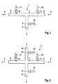
- FIG. 1 has a purely schematically illustrated shut-off valve 1 to a flow line 2 through which in the direction of arrow, for example beer is transportable.
- the valve has an inlet channel 3, which can be shut off with an inlet valve 4.
- the valve has an outlet channel 5, which can be shut off with an outlet valve 6.
- a leakage chamber 7 is formed, from which a leakage channel 8 leads away.
- the leakage channel can be locked with a leakage valve 9.
- All valves are pinch valves, which can be actuated or squeezed together via suitable blocking means 10, 11, 12.
- the simplest version of such a shut-off valve consists of a T-shaped flexible hose, which is integrated in the flow line 2.
- the wall of the hose forms the actual valve at the inlet channel, at the outlet channel and at the leakage channel.
- This valve is relatively simple. When uncoupling the flow line 2, for example, for rinsing with cleaning liquid in the flow direction after the outlet valve 6, the inlet valve 4 and the outlet valve 6 are closed while the leakage valve 9 is opened. Cleaning liquid, which nevertheless penetrate the outlet valve 6 could, can not get into the inlet channel, but is discharged through the leakage channel 8.
- the shut-off valve 1 is substantially the same as in accordance with FIG. 1 ,
- the leakage chamber 7 is also connected to a flushing channel 14, which can be shut off via a flush valve 15.
- This has its own blocking means 13.
- both the leakage valve 9 and the flush valve 15 are closed, while the inlet valve 4 and the outlet valve 6 are opened.
- the flush valve 15 can also be opened in order to flush the leakage chamber 9 with a neutral flushing liquid, before the flow line 2 is again released.
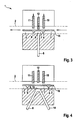
- FIG. 3 The same functional principle as in FIG. 1 but with a common crush diaphragm for the different valves is in FIG. 3 shown.
- the Quetschmembran 16 extends oblong over the entire leakage space and partially into the inlet channel 3 and in the outlet channel 5.
- the valve seats for the inlet valve 4, the outlet valve 6 and the leakage valve 9 are shown to lie on a common plane, so that the Quetschmembran 16th can be squeezed with the alternately operable locking means 10, 11 and 12.
- These locking means are rams that can be raised or lowered by means of a controller not shown here.
- the locking means 10 and 11 are raised, while the locking means 12 is lowered, and it is evident that the leakage valve 9 closes.
- the two locking means 10 and 11 is lowered, so that the inlet valve 4 and the outlet valve 6 close, while the locking means 12 is raised and the Quetschmembran 16 thus the leakage valve 9 and the leakage channel 8 releases.
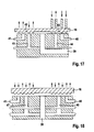
- the shut-off valve is similar in function FIG. 4 , Here, however, still leads a flushing channel 14 in the leakage chamber 7, wherein the inlet opening of the flushing channel coincides with the outlet opening of the leakage channel 8. These common openings thereby form a common leakage valve 9 or a flushing valve 15, which can be closed by lowering the blocking means 12.
- the function of the inlet valve 4 and the outlet valve 6 is the same as in the embodiment according to FIG. 3 , Evidently, it is not possible here, for example, to shut off the flushing channel 14 independently of the leakage channel 8 with respect to the leakage chamber.
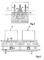
- the flushing channel 14 is guided concentrically in the leakage channel 8 to the leakage chamber 7, so that the leakage channel 8 forms an annular orifice.
- a concentric double ram is arranged, which forms the blocking means 12 for the leakage valve 9 and the blocking means for the flush valve 15.
- the flushing channel can thus be closed separately by pressing the inner plunger 13 against the quenching membrane.
- the leakage valve 9 remains open so that leakage can be dissipated when the inlet valve 4 and the outlet valve 6 are closed.
- the flushing channel 14 can also be opened, which allows a flushing of the leakage chamber 7.
- the leakage space can also be compared Seal the flow channel 2 separately so that product is feasible while the leakage chamber is flushed. If the two plungers 12 and 13 lowered together, both the leakage channel 8 and the purge passage 14 is shut off from the leakage chamber 7 and with open inlet valve 4 and outlet valve 6 can flow normally product through the flow line.
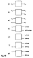
- FIG. 6 a whole battery of shut-off valves 1a and 1b are coupled together in series. As shown, a common, past all shut-off valves guided leakage channel 8 and a common flushing channel 14 is formed. Nevertheless, it is not absolutely necessary that all shut-off valves must be flushed together and in series. Rather, it allows the individual shut-off possibility of leakage channel 8 and flushing channel 14 at each shut-off valve to make a selective flushing. For example, it could be seen in the shut-off valve 1 in a viewing window 21 that leakage penetrates into the leakage channel 8. For rinsing the respective leakage chamber 7a, the flushing valve 15a can be opened, while the shut-off valve 1b is not flushed. The presence of leakage in the leakage channel 8 could be determined, for example, by a suitable sensor 22.
- FIGS. 3 to 6 described embodiments with the common Quetschmembran have the considerable advantage that no dead space remains in which bacterial herds could settle. This is achieved primarily by the arrangement of the valve seats on a common plane.
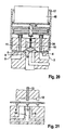
- FIGS. 7 to 9 is a further embodiment of a shut-off valve shown, which is substantially the embodiment according to FIG. 5 equivalent. Shown here is primarily how the individual locking means for the valves in the common valve housing 17 cooperate.
- the common Quetschmembran 16 act as a blocking means, the two plungers 10 and 11 for the actuation of the inlet valve 4 and the outlet valve 6. These two plungers are acted upon by a common control plate 19 so that they can be raised or lowered according to their function.
- the two concentric rams 12 and 13 are arranged, which are each operable separately.
- a acted upon by a spring 23 piston 20 has a piston rod 24 which is guided in a fixedly anchored in the valve housing 17 support plate 18.
- the inlet valve 4 and the outlet valve 6 are closed, while the leakage chamber 7 is opened.
- the purge valve 15 is closed.
- the inlet valve 4 and the outlet valve 6 are opened and normal product flows through the flow line 2 while the flushing valve remains open.
- the leakage valve 9 is closed and the leakage space sealed by the flow line, so that it is individually flushable.
- the opening of the purge valve 15 is effected in that the piston rod 24 lifts from the spring-loaded spool 28, so that the concentric inner plunger 13 can lift under spring preload.
- shut-off valve is shown in the same operating position as at FIG. 9 , In this design, however, a defined relief is possible, with an additional pressure chamber 29 and a connecting channel 30 is provided to the small pressure chamber 26. When pressure build-up in the small pressure chamber 26 can thus also flow compressed air into the additional pressure chamber 29.
- the additional pressure chamber is again closed because it is separated from the connecting channel. Leakage valve 9 and flush valve 15 are then closed.
- the additional pressure chamber 29 is released only when the inlet valve 4 and the outlet valve 6 are closed, because only when completely lowered piston rod 24, the connecting channel is released again. This ensures that the leakage valve 9 opens only when the product line is closed. This security feature when relieving could also be achieved purely mechanically.
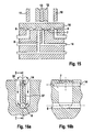
- FIGS. 11 to 13 a mechanical solution provided in FIG. 14 is shown in more detail.
- the actuation of the purge valve takes place via a locking pusher 31, which is mounted vertically displaceably on an actuating spindle 32.
- a driver 33 at the end of the spindle 32 can raise or release the pawl 31 either against the force of a compression spring 36, so that it is pressed against the Quetschmembran 16.
- shut-off valve In the first operating position according to FIG. 11 the shut-off valve is pneumatically depressurized, that is, the compression spring 23 presses the piston 20 with its piston rod 24 down, the spindle 32, the locking pestle 31 releases.
- the rocker 34 is moved to a position in which it raises the buckle 35. In this position, the purge valve 15 is closed and the leakage valve 9 is opened. At the same time inlet valve 4 and outlet valve 6 are closed.
- FIG. 15 is functionally comparable to that according to FIG. 5 , however, the flushing channel 14 and the leakage channel 8 open not concentric in the leakage chamber 7, but next to each other. However, the locking means 12 and 13 may still be formed as a concentric nested plunger.
- FIGS. 16a and 16b show how the leakage channel 8 and the flushing channel 14 can be arranged to avoid dead spaces despite concentric arrangement.
- the two channels lie one above the other on a vertical plane, wherein a block of material connects the channel walls together.
- Starting from the annular leakage chamber 7 lead lateral pockets or cavities 38 on both sides of the material block 37 down and open on both sides in the leakage channel 8.
- Leakage flows even in the pressureless state always down in the vertical leakage channel 8 and can not accumulate on undercuts , whereby bacterial herds could form.
- rinsing the leakage chamber 7 rinsing liquid flows through the rinsing channel 14 under pressure and residual leakage is flushed away through the leakage channel 8.
- the embodiment according to FIG. 17 shows according to the principle described so far, a three-way valve, starting from a Product main 39 allows the supply of a first outlet line 40 and a second outlet line 41. Accordingly, a first leakage space 42 and a second leakage space 43 are provided. These leakage chambers also have separate leakage channels 44 and 45, which, however, lead to a common collection channel. The operation of the inlet valve, the outlet valve and the leakage valve is carried out separately for each outlet channel in the same or similar manner as in the described embodiments.
- the embodiment according to FIG. 18 shows a three-way valve analogous to the embodiment according to FIG. 17 , but still with an additional flushing option via a first flushing channel 46 and a second flushing channel 47. These two flushing channels in turn lead to a common manifold. Accordingly, each again a separate flush valve is required to shut off the associated flushing channel.
- FIG. 21 another similar valve arrangement for the leakage valve and the purge valve as at FIG. 5
- the flushing channel 14 is not concentric, but eccentrically guided in the leakage channel 8. Accordingly eccentric is the arrangement of the two plungers 12 and 13th
Landscapes
- Engineering & Computer Science (AREA)
- General Engineering & Computer Science (AREA)
- Mechanical Engineering (AREA)
- Multiple-Way Valves (AREA)
- Details Of Valves (AREA)
- Pipeline Systems (AREA)
Claims (13)
- Soupape d'arrêt (1) avec fonction de fuite pour le blocage d'un canal d'écoulement (2), comprenant :- un canal d'entrée (3) avec une soupape d'entrée (4),- un canal de sortie (5) avec une soupape de sortie (6),- un espace de fuite (7) disposé entre la soupape d'entrée et la soupape de sortie,- et au moins un canal de fuite (8) conduisant hors de l'espace de fuite, avec une soupape de fuite (9),
caractérisée en ce que- les soupapes sont des soupapes à pince pouvant être actionnées en alternance constituées d'un tuyau flexible ou d'une membrane à pince flexible, chaque soupape à pince présentant un moyen d'arrêt (10, 11, 12) qui peut être pressé contre le tuyau ou contre la membrane à pince. - Soupape d'arrêt selon la revendication 1, caractérisée en ce qu'un canal de rinçage (14) conduit vers l'espace de fuite (7), lequel présente une soupape de rinçage (15) qui est réalisée également sous forme de soupape à pince avec un moyen d'arrêt (13).
- Soupape d'arrêt selon la revendication 1 ou 2, caractérisée en ce que les sièges de soupape de toutes les soupapes à pince se situent approximativement dans le même plan et en ce que les soupapes à pince peuvent être actionnées par le biais d'une membrane à pince commune (16).
- Soupape d'arrêt selon la revendication 2 et la revendication 3, caractérisée en ce que le canal de fuite (8) et le canal de rinçage (14) sont guidés, en tant que canaux disposés concentriquement ou excentriquement l'un dans l'autre, dans l'espace de fuite (7), dont les ouvertures d'entrée peuvent être fermées séparément au moyen de la membrane à pince.
- Soupape d'arrêt selon la revendication 4, caractérisée en ce que les moyens d'arrêt pour la soupape de fuite (9) et pour la soupape de rinçage (15) sont deux poussoirs guidés concentriquement ou excentriquement l'un dans l'autre, qui peuvent être pressés en alternance ou en commun contre la membrane à pince.
- Soupape d'arrêt selon la revendication 2 et la revendication 3, caractérisée en ce que le canal de fuite (8) et le canal de rinçage (14) sont guidés, en tant que canaux juxtaposés, dans l'espace de fuite (7), dont les ouvertures d'entrée peuvent être fermée séparément au moyen de la membrane à pince (16).
- Soupape d'arrêt selon la revendication 1, caractérisée en ce qu'au moins un deuxième canal de sortie avec une deuxième soupape de sortie et avec un deuxième espace de fuite disposé entre la soupape d'entrée et la deuxième soupape de sortie est prévu, depuis lequel part un deuxième canal de fuite avec une deuxième soupape de fuite, la deuxième soupape de sortie et la deuxième soupape de fuite étant également des soupapes à pince à actionnement en alternance ayant chacune un moyen d'arrêt.
- Soupape d'arrêt selon la revendication 7, caractérisée en ce qu'un canal de rinçage respectif conduit vers l'espace de fuite et vers le deuxième espace de fuite, lequel canal de rinçage présente une soupape de rinçage qui est réalisée également sous forme de soupape à pince avec un moyen d'arrêt.
- Soupape d'arrêt selon la revendication 4, caractérisée en ce que le canal de fuite et le canal de rinçage sont disposés de telle sorte qu'il n'existe aucun espace mort ne pouvant pas être parcouru par un écoulement de liquide de rinçage.
- Soupape d'arrêt selon l'une quelconque des revendications 1 à 9, caractérisée en ce qu'une fenêtre de vision est disposée dans le canal de fuite (8) et/ou dans l'espace de fuite (7).
- Soupape d'arrêt selon l'une quelconque des revendications 1 à 10, caractérisée en ce que les moyens d'arrêt pour les soupapes à pince peuvent être activés de manière pneumatique et/ou électromécanique.
- Soupape d'arrêt selon la revendication 11, caractérisée en ce que les moyens d'arrêt peuvent être commandés de manière définie de telle sorte que dans une première position de fonctionnement, lorsque la soupape d'entrée est fermée et que la soupape de sortie est fermée, la soupape de fuite est ouverte, et que, dans une deuxième position de fonctionnement, lorsque la soupape d'entrée est ouverte et que la soupape de sortie est ouverte, la soupape de fuite est fermée, et en cas d'inversion entre les deux positions de fonctionnement, à chaque fois dans une position de fonctionnement intermédiaire, la soupape d'entrée, la soupape de sortie et la soupape de fuite sont toutes fermées.
- Agencement de soupape d'arrêt, caractérisé en ce que les canaux de fuite et les canaux de rinçage de plusieurs soupapes d'arrêt (1a, 1b) selon la revendication 2 et l'une quelconque des revendications 3 à 12, sont raccordés les uns aux autres.
Applications Claiming Priority (3)
| Application Number | Priority Date | Filing Date | Title |
|---|---|---|---|
| CH15042006 | 2006-09-18 | ||
| CH15712006 | 2006-10-03 | ||
| PCT/EP2007/058837 WO2008034686A1 (fr) | 2006-09-18 | 2007-08-24 | Soupape d'arrêt avec fonction de fuite |
Publications (2)
| Publication Number | Publication Date |
|---|---|
| EP2064468A1 EP2064468A1 (fr) | 2009-06-03 |
| EP2064468B1 true EP2064468B1 (fr) | 2011-07-06 |
Family
ID=38694932
Family Applications (1)
| Application Number | Title | Priority Date | Filing Date |
|---|---|---|---|
| EP07788534A Not-in-force EP2064468B1 (fr) | 2006-09-18 | 2007-08-24 | Soupape d'arrêt avec fonction de fuite |
Country Status (3)
| Country | Link |
|---|---|
| EP (1) | EP2064468B1 (fr) |
| AT (1) | ATE515654T1 (fr) |
| WO (1) | WO2008034686A1 (fr) |
Families Citing this family (3)
| Publication number | Priority date | Publication date | Assignee | Title |
|---|---|---|---|---|
| US9322482B2 (en) | 2012-07-20 | 2016-04-26 | Itt Manufacturing Enterprises Llc. | Temperature compensating flanged joint for a teflon diaphragm valve |
| US9157534B2 (en) | 2012-07-20 | 2015-10-13 | Itt Manufacturing Enterprises Llc. | Two-stud diaphragm for diaphragm valves |
| US9016307B2 (en) | 2012-07-20 | 2015-04-28 | Itt Manufacturing Enterprises Llc. | Quick connect, post energized flanged joint for a diaphragm valve |
Family Cites Families (3)
| Publication number | Priority date | Publication date | Assignee | Title |
|---|---|---|---|---|
| JP2660188B2 (ja) * | 1990-11-08 | 1997-10-08 | ティ・エフ・シィ株式会社 | 三方切替弁 |
| SE501377C2 (sv) * | 1993-06-17 | 1995-01-30 | Ingvar Baecklund | Trevägs membranventilanordning |
| DE20009697U1 (de) * | 2000-05-31 | 2000-08-24 | Rieger Gmbh & Co Kg Geb | Ventil, insbesondere für nahrungsmittelverarbeitende und kosmetische Anlagen |
-
2007
- 2007-08-24 WO PCT/EP2007/058837 patent/WO2008034686A1/fr active Application Filing
- 2007-08-24 EP EP07788534A patent/EP2064468B1/fr not_active Not-in-force
- 2007-08-24 AT AT07788534T patent/ATE515654T1/de active
Also Published As
| Publication number | Publication date |
|---|---|
| EP2064468A1 (fr) | 2009-06-03 |
| ATE515654T1 (de) | 2011-07-15 |
| WO2008034686A1 (fr) | 2008-03-27 |
Similar Documents
| Publication | Publication Date | Title |
|---|---|---|
| EP0381069B1 (fr) | Manchon d'accouplement pour lignes d'interconnexion hydraulique | |
| DE3717341C2 (fr) | ||
| EP1357325B1 (fr) | Raccord rapide | |
| EP2397732B1 (fr) | Dispositif d'entraînement d'une soupape à double siège | |
| DE102011077717B4 (de) | Doppelsitzventil-Vorrichtung mit Festkörperkontakt | |
| EP1952046B1 (fr) | Soupape a double siege | |
| EP3535509B1 (fr) | Robinet à boisseau sphérique pour un système de conduites acheminant des fluides liquides ou gazeux | |
| DE102015221940B3 (de) | Ventilanordnung | |
| EP2501969B1 (fr) | Vanne pour condensat | |
| EP2064468B1 (fr) | Soupape d'arrêt avec fonction de fuite | |
| EP3087279B1 (fr) | Ensemble de soupapes | |
| EP1032375A1 (fr) | Distributeur hydraulique | |
| DE4129755C2 (de) | Doppelsitz-Ventilanordnung | |
| EP3070383B1 (fr) | Servo-soupape | |
| DE102014101339B4 (de) | Membranventil | |
| DE3637345C2 (fr) | ||
| DE19822424C2 (de) | Doppelsitzventil mit Leckkontrolle | |
| EP0100330B1 (fr) | Dispositif de commande hydraulique | |
| WO1989005382A1 (fr) | Clapet de non-retour, notamment pour conduits d'eau potable | |
| WO2014008880A2 (fr) | Système de conduites pour le transport de liquides | |
| DE2143653C (de) | Ventil, bestehend aus einem Hauptventil und einem Hilfsventil | |
| DE4129352A1 (de) | Systemtrenngeraet | |
| DE19654254C2 (de) | Mehrfach-Sitzventil | |
| DE2536784B2 (de) | Hydraulische Ventileinrichtung zur Wegesteuerung des Arbeitsdruckmittels für einen hydraulischen Servomotor | |
| AT16375U1 (de) | Ventil |
Legal Events
| Date | Code | Title | Description |
|---|---|---|---|
| PUAI | Public reference made under article 153(3) epc to a published international application that has entered the european phase |
Free format text: ORIGINAL CODE: 0009012 |
|
| 17P | Request for examination filed |
Effective date: 20090312 |
|
| AK | Designated contracting states |
Kind code of ref document: A1 Designated state(s): AT BE BG CH CY CZ DE DK EE ES FI FR GB GR HU IE IS IT LI LT LU LV MC MT NL PL PT RO SE SI SK TR |
|
| AX | Request for extension of the european patent |
Extension state: AL BA HR MK RS |
|
| 17Q | First examination report despatched |
Effective date: 20090810 |
|
| GRAP | Despatch of communication of intention to grant a patent |
Free format text: ORIGINAL CODE: EPIDOSNIGR1 |
|
| DAX | Request for extension of the european patent (deleted) | ||
| GRAS | Grant fee paid |
Free format text: ORIGINAL CODE: EPIDOSNIGR3 |
|
| GRAA | (expected) grant |
Free format text: ORIGINAL CODE: 0009210 |
|
| AK | Designated contracting states |
Kind code of ref document: B1 Designated state(s): AT BE BG CH CY CZ DE DK EE ES FI FR GB GR HU IE IS IT LI LT LU LV MC MT NL PL PT RO SE SI SK TR |
|
| REG | Reference to a national code |
Ref country code: GB Ref legal event code: FG4D Free format text: NOT ENGLISH |
|
| REG | Reference to a national code |
Ref country code: CH Ref legal event code: EP |
|
| REG | Reference to a national code |
Ref country code: IE Ref legal event code: FG4D Free format text: LANGUAGE OF EP DOCUMENT: GERMAN |
|
| REG | Reference to a national code |
Ref country code: DE Ref legal event code: R096 Ref document number: 502007007617 Country of ref document: DE Effective date: 20110901 |
|
| REG | Reference to a national code |
Ref country code: NL Ref legal event code: VDEP Effective date: 20110706 |
|
| PG25 | Lapsed in a contracting state [announced via postgrant information from national office to epo] |
Ref country code: SI Free format text: LAPSE BECAUSE OF FAILURE TO SUBMIT A TRANSLATION OF THE DESCRIPTION OR TO PAY THE FEE WITHIN THE PRESCRIBED TIME-LIMIT Effective date: 20110706 |
|
| REG | Reference to a national code |
Ref country code: CH Ref legal event code: NV Representative=s name: HEPP WENGER RYFFEL AG |
|
| PG25 | Lapsed in a contracting state [announced via postgrant information from national office to epo] |
Ref country code: MT Free format text: LAPSE BECAUSE OF FAILURE TO SUBMIT A TRANSLATION OF THE DESCRIPTION OR TO PAY THE FEE WITHIN THE PRESCRIBED TIME-LIMIT Effective date: 20110706 |
|
| PG25 | Lapsed in a contracting state [announced via postgrant information from national office to epo] |
Ref country code: SE Free format text: LAPSE BECAUSE OF FAILURE TO SUBMIT A TRANSLATION OF THE DESCRIPTION OR TO PAY THE FEE WITHIN THE PRESCRIBED TIME-LIMIT Effective date: 20110706 Ref country code: IS Free format text: LAPSE BECAUSE OF FAILURE TO SUBMIT A TRANSLATION OF THE DESCRIPTION OR TO PAY THE FEE WITHIN THE PRESCRIBED TIME-LIMIT Effective date: 20111106 Ref country code: LT Free format text: LAPSE BECAUSE OF FAILURE TO SUBMIT A TRANSLATION OF THE DESCRIPTION OR TO PAY THE FEE WITHIN THE PRESCRIBED TIME-LIMIT Effective date: 20110706 Ref country code: NL Free format text: LAPSE BECAUSE OF FAILURE TO SUBMIT A TRANSLATION OF THE DESCRIPTION OR TO PAY THE FEE WITHIN THE PRESCRIBED TIME-LIMIT Effective date: 20110706 Ref country code: FI Free format text: LAPSE BECAUSE OF FAILURE TO SUBMIT A TRANSLATION OF THE DESCRIPTION OR TO PAY THE FEE WITHIN THE PRESCRIBED TIME-LIMIT Effective date: 20110706 Ref country code: PT Free format text: LAPSE BECAUSE OF FAILURE TO SUBMIT A TRANSLATION OF THE DESCRIPTION OR TO PAY THE FEE WITHIN THE PRESCRIBED TIME-LIMIT Effective date: 20111107 |
|
| REG | Reference to a national code |
Ref country code: IE Ref legal event code: FD4D |
|
| BERE | Be: lapsed |
Owner name: LOCHER, KARL Effective date: 20110831 |
|
| PG25 | Lapsed in a contracting state [announced via postgrant information from national office to epo] |
Ref country code: LV Free format text: LAPSE BECAUSE OF FAILURE TO SUBMIT A TRANSLATION OF THE DESCRIPTION OR TO PAY THE FEE WITHIN THE PRESCRIBED TIME-LIMIT Effective date: 20110706 Ref country code: GR Free format text: LAPSE BECAUSE OF FAILURE TO SUBMIT A TRANSLATION OF THE DESCRIPTION OR TO PAY THE FEE WITHIN THE PRESCRIBED TIME-LIMIT Effective date: 20111007 Ref country code: CY Free format text: LAPSE BECAUSE OF FAILURE TO SUBMIT A TRANSLATION OF THE DESCRIPTION OR TO PAY THE FEE WITHIN THE PRESCRIBED TIME-LIMIT Effective date: 20110706 Ref country code: PL Free format text: LAPSE BECAUSE OF FAILURE TO SUBMIT A TRANSLATION OF THE DESCRIPTION OR TO PAY THE FEE WITHIN THE PRESCRIBED TIME-LIMIT Effective date: 20110706 |
|
| PG25 | Lapsed in a contracting state [announced via postgrant information from national office to epo] |
Ref country code: MC Free format text: LAPSE BECAUSE OF NON-PAYMENT OF DUE FEES Effective date: 20110831 |
|
| PG25 | Lapsed in a contracting state [announced via postgrant information from national office to epo] |
Ref country code: CZ Free format text: LAPSE BECAUSE OF FAILURE TO SUBMIT A TRANSLATION OF THE DESCRIPTION OR TO PAY THE FEE WITHIN THE PRESCRIBED TIME-LIMIT Effective date: 20110706 Ref country code: IE Free format text: LAPSE BECAUSE OF FAILURE TO SUBMIT A TRANSLATION OF THE DESCRIPTION OR TO PAY THE FEE WITHIN THE PRESCRIBED TIME-LIMIT Effective date: 20110706 Ref country code: SK Free format text: LAPSE BECAUSE OF FAILURE TO SUBMIT A TRANSLATION OF THE DESCRIPTION OR TO PAY THE FEE WITHIN THE PRESCRIBED TIME-LIMIT Effective date: 20110706 |
|
| PLBE | No opposition filed within time limit |
Free format text: ORIGINAL CODE: 0009261 |
|
| STAA | Information on the status of an ep patent application or granted ep patent |
Free format text: STATUS: NO OPPOSITION FILED WITHIN TIME LIMIT |
|
| PG25 | Lapsed in a contracting state [announced via postgrant information from national office to epo] |
Ref country code: EE Free format text: LAPSE BECAUSE OF FAILURE TO SUBMIT A TRANSLATION OF THE DESCRIPTION OR TO PAY THE FEE WITHIN THE PRESCRIBED TIME-LIMIT Effective date: 20110706 Ref country code: BE Free format text: LAPSE BECAUSE OF NON-PAYMENT OF DUE FEES Effective date: 20110831 Ref country code: RO Free format text: LAPSE BECAUSE OF FAILURE TO SUBMIT A TRANSLATION OF THE DESCRIPTION OR TO PAY THE FEE WITHIN THE PRESCRIBED TIME-LIMIT Effective date: 20110706 Ref country code: IT Free format text: LAPSE BECAUSE OF FAILURE TO SUBMIT A TRANSLATION OF THE DESCRIPTION OR TO PAY THE FEE WITHIN THE PRESCRIBED TIME-LIMIT Effective date: 20110706 |
|
| 26N | No opposition filed |
Effective date: 20120411 |
|
| PG25 | Lapsed in a contracting state [announced via postgrant information from national office to epo] |
Ref country code: DK Free format text: LAPSE BECAUSE OF FAILURE TO SUBMIT A TRANSLATION OF THE DESCRIPTION OR TO PAY THE FEE WITHIN THE PRESCRIBED TIME-LIMIT Effective date: 20110706 |
|
| REG | Reference to a national code |
Ref country code: DE Ref legal event code: R097 Ref document number: 502007007617 Country of ref document: DE Effective date: 20120411 |
|
| PG25 | Lapsed in a contracting state [announced via postgrant information from national office to epo] |
Ref country code: ES Free format text: LAPSE BECAUSE OF FAILURE TO SUBMIT A TRANSLATION OF THE DESCRIPTION OR TO PAY THE FEE WITHIN THE PRESCRIBED TIME-LIMIT Effective date: 20111017 |
|
| PG25 | Lapsed in a contracting state [announced via postgrant information from national office to epo] |
Ref country code: LU Free format text: LAPSE BECAUSE OF NON-PAYMENT OF DUE FEES Effective date: 20110824 |
|
| PG25 | Lapsed in a contracting state [announced via postgrant information from national office to epo] |
Ref country code: BG Free format text: LAPSE BECAUSE OF FAILURE TO SUBMIT A TRANSLATION OF THE DESCRIPTION OR TO PAY THE FEE WITHIN THE PRESCRIBED TIME-LIMIT Effective date: 20111006 |
|
| PG25 | Lapsed in a contracting state [announced via postgrant information from national office to epo] |
Ref country code: TR Free format text: LAPSE BECAUSE OF FAILURE TO SUBMIT A TRANSLATION OF THE DESCRIPTION OR TO PAY THE FEE WITHIN THE PRESCRIBED TIME-LIMIT Effective date: 20110706 |
|
| PG25 | Lapsed in a contracting state [announced via postgrant information from national office to epo] |
Ref country code: HU Free format text: LAPSE BECAUSE OF FAILURE TO SUBMIT A TRANSLATION OF THE DESCRIPTION OR TO PAY THE FEE WITHIN THE PRESCRIBED TIME-LIMIT Effective date: 20110706 |
|
| REG | Reference to a national code |
Ref country code: FR Ref legal event code: PLFP Year of fee payment: 10 |
|
| REG | Reference to a national code |
Ref country code: FR Ref legal event code: PLFP Year of fee payment: 11 |
|
| PGFP | Annual fee paid to national office [announced via postgrant information from national office to epo] |
Ref country code: DE Payment date: 20170815 Year of fee payment: 11 Ref country code: FR Payment date: 20170829 Year of fee payment: 11 Ref country code: GB Payment date: 20170823 Year of fee payment: 11 |
|
| PGFP | Annual fee paid to national office [announced via postgrant information from national office to epo] |
Ref country code: AT Payment date: 20170825 Year of fee payment: 11 |
|
| PGFP | Annual fee paid to national office [announced via postgrant information from national office to epo] |
Ref country code: CH Payment date: 20171030 Year of fee payment: 11 |
|
| REG | Reference to a national code |
Ref country code: DE Ref legal event code: R119 Ref document number: 502007007617 Country of ref document: DE |
|
| REG | Reference to a national code |
Ref country code: CH Ref legal event code: PL |
|
| REG | Reference to a national code |
Ref country code: AT Ref legal event code: MM01 Ref document number: 515654 Country of ref document: AT Kind code of ref document: T Effective date: 20180824 |
|
| GBPC | Gb: european patent ceased through non-payment of renewal fee |
Effective date: 20180824 |
|
| PG25 | Lapsed in a contracting state [announced via postgrant information from national office to epo] |
Ref country code: AT Free format text: LAPSE BECAUSE OF NON-PAYMENT OF DUE FEES Effective date: 20180824 Ref country code: LI Free format text: LAPSE BECAUSE OF NON-PAYMENT OF DUE FEES Effective date: 20180831 Ref country code: CH Free format text: LAPSE BECAUSE OF NON-PAYMENT OF DUE FEES Effective date: 20180831 |
|
| PG25 | Lapsed in a contracting state [announced via postgrant information from national office to epo] |
Ref country code: DE Free format text: LAPSE BECAUSE OF NON-PAYMENT OF DUE FEES Effective date: 20190301 |
|
| PG25 | Lapsed in a contracting state [announced via postgrant information from national office to epo] |
Ref country code: FR Free format text: LAPSE BECAUSE OF NON-PAYMENT OF DUE FEES Effective date: 20180831 |
|
| PG25 | Lapsed in a contracting state [announced via postgrant information from national office to epo] |
Ref country code: GB Free format text: LAPSE BECAUSE OF NON-PAYMENT OF DUE FEES Effective date: 20180824 |