EP2063699B1 - Blattsauger und -häcksler - Google Patents
Blattsauger und -häcksler Download PDFInfo
- Publication number
- EP2063699B1 EP2063699B1 EP07873330A EP07873330A EP2063699B1 EP 2063699 B1 EP2063699 B1 EP 2063699B1 EP 07873330 A EP07873330 A EP 07873330A EP 07873330 A EP07873330 A EP 07873330A EP 2063699 B1 EP2063699 B1 EP 2063699B1
- Authority
- EP
- European Patent Office
- Prior art keywords
- mulcher
- shredding blade
- shredder
- recited
- separable
- Prior art date
- Legal status (The legal status is an assumption and is not a legal conclusion. Google has not performed a legal analysis and makes no representation as to the accuracy of the status listed.)
- Expired - Fee Related
Links
Images


Classifications
-
- A—HUMAN NECESSITIES
- A01—AGRICULTURE; FORESTRY; ANIMAL HUSBANDRY; HUNTING; TRAPPING; FISHING
- A01G—HORTICULTURE; CULTIVATION OF VEGETABLES, FLOWERS, RICE, FRUIT, VINES, HOPS OR SEAWEED; FORESTRY; WATERING
- A01G3/00—Cutting implements specially adapted for horticultural purposes; Delimbing standing trees
- A01G3/002—Cutting implements specially adapted for horticultural purposes; Delimbing standing trees for comminuting plant waste
-
- B—PERFORMING OPERATIONS; TRANSPORTING
- B02—CRUSHING, PULVERISING, OR DISINTEGRATING; PREPARATORY TREATMENT OF GRAIN FOR MILLING
- B02C—CRUSHING, PULVERISING, OR DISINTEGRATING IN GENERAL; MILLING GRAIN
- B02C18/00—Disintegrating by knives or other cutting or tearing members which chop material into fragments
- B02C18/06—Disintegrating by knives or other cutting or tearing members which chop material into fragments with rotating knives
- B02C18/08—Disintegrating by knives or other cutting or tearing members which chop material into fragments with rotating knives within vertical containers
- B02C18/10—Disintegrating by knives or other cutting or tearing members which chop material into fragments with rotating knives within vertical containers with drive arranged above container
-
- B—PERFORMING OPERATIONS; TRANSPORTING
- B02—CRUSHING, PULVERISING, OR DISINTEGRATING; PREPARATORY TREATMENT OF GRAIN FOR MILLING
- B02C—CRUSHING, PULVERISING, OR DISINTEGRATING IN GENERAL; MILLING GRAIN
- B02C18/00—Disintegrating by knives or other cutting or tearing members which chop material into fragments
- B02C18/06—Disintegrating by knives or other cutting or tearing members which chop material into fragments with rotating knives
- B02C18/16—Details
Definitions
- This disclosure generally relates to products used to clean residential yards, and more particularly to products used to collect and dispose of fallen leaves or yard waste.
- WO-A-97/44998 discloses an apparatus in which a fan draws air in and drives it in a distal to proximal direction through a duct and a shroud, and into a debris bag.
- the applicants have developed a mulcher that has a removable shedder assembly that enables the product to be used for shredding leaves, yard waste, or other relatively lightweight materials.
- the shredder assembly can also be removed, enabling the vacuum to be used as a conventional utility vacuum. Because utility vacuums are used during all seasons, the product has more overall use.
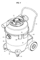
- Fig. 1 is an isometric view of one embodiment of a mulcher that incorporates the new invention.
- Fig. 2 is a top plan view of the mulcher.
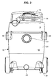
- Fig. 3 is a front elevation view of the mulcher.
- Fig. 4 is a left-side elevation view of the mulcher.
- Fig. 5 is a back elevation view of the mulcher.
- Fig. 6 is a right-side elevation view of the mulcher.
- Fig. 7 is a bottom view of the mulcher.
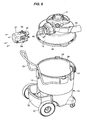
- Fig. 8 is a partially exploded perspective view of the mulcher.
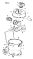
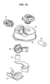
- Figs. 9 and 10 are further exploded perspective views of the mulcher.
- Fig. 11 is an exploded perspective view of the motor unit for the mulcher.
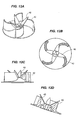
- Fig. 12a is a perspective view of blades in the shredder assembly.
- Fig. 12b is a top view of the blades seen in fig. 12a .
- Fig. 12c is a side view of the blades.
- Fig. 12d is a cross-sectional side view of the blades.
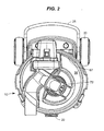
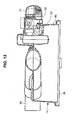
- Fig. 13 is a side sectional view of a portion of the mulcher.
- Figs. 14a and b are enlarged cross-sectional views through sections of the shredder assembly.
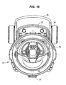
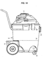
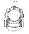
- Figs. 15-21 are views of the mulcher corresponding to figs. 1-8 but with the shredder assembly having been replaced by a basic head unit.
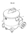
- Fig. 22 is an isometric view of another embodiment of a mulcher that incorporates the new invention.
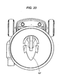
- Fig. 23 is a top plan view of the mulcher of figure 22 .
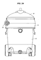
- Fig. 24 is a front elevation view of that mulcher.
- Fig. 25 is a left-side elevation view of that mulcher.
- Fig. 26 is a back elevation view of that mulcher.
- Fig. 27 is a right-side elevation view of that mulcher.
- Fig. 28 is a bottom view of that mulcher.
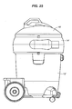
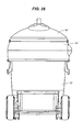
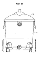
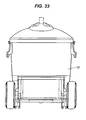
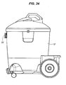
- Figs. 29-35 are views that correspond with figures 22-28 , but show the mulcher with the shredder assembly removed.
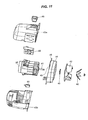
- Fig. 36 is an exploded partial perspective view of the shredder assembly that is used with this embodiment of the invention, along with a conical filter.
- Fig. 37 is a cross-section view of the mulcher.
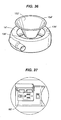
- Fig. 38 is an enlarged view of an electrical receptacle on the shredder assembly.
- Fig. 39 is a perspective view of a detachable blower that can be incorporated into a head unit in the mulcher.
- Fig. 40 is a side elevation view of an alternative arrangement of a detachable blower.
- the illustrated mulcher has three primary parts: a base unit 12, a shredder assembly 14 (seen in figs. 1-8 ), and a basic head unit 16 (seen in figs. 15-21 ). Each part will be described in turn.
- the illustrated base unit 12 has a tank wall 20, a closeable port 22, and an open top 24 (see figs. 8 and 9 ).
- the volume within the tank wall 20 defines a tank chamber (or storage reservoir) that is used to store collected dirt and debris, and can vary in size to meet consumer demands.
- the port can be used as an inlet during conventional vacuuming, or sealed with a cap (not shown) during mulching.
- the open top accommodates either the shredder assembly 14 (during mulching) or the head unit 16 (during conventional vacuuming).
- the base unit 12 can also include optional features like wheels or casters 30, a storage compartment 32, or a drain 34 for a wet/dry vacuum.
- a handle 35 can also be attached.
- the shredder assembly 14 (best seen in figs. 8-14 ) has a mulching inlet 36, a power module 37, and a lower rim 38.
- the mulching inlet can be used to collect leaves or other yard waste.
- the illustrated mulching inlet is part of a pathway that is relatively straight and has a relatively wide diameter. It has only two turns, each through an angle of less than 45°. Together with the 3 1 ⁇ 2" diameter of the inlet and its relatively short length (less than 10"), the straightness of this pathway provides a clog-resistant, easy-feeding inlet for leaves or yard waste. Other arrangements are possible, but it is preferred that the pathway to the power module be relatively wide and straight.
- the power module 37 cuts the material that is drawn in through the mulching inlet 36.
- the illustrated power module is powered by a motor 39, and preferably has a mulcher (or shredding) blade 40 that is optimized for shredding leaves, rather than for moving air.
- the shredding blade is mounted in front of and on the same shaft 41 as optional air impeller blades 42.
- the air impeller blades help to draw material to the shredding blade.
- the illustrated shredding blade is made of metal, and sits on top of and is supported by plastic impeller blades. This arrangement may help to prevent the shredding blade from deforming under centripetal force.
- the illustrated motor 39 is mounted between top and bottom covers 43a and 43b that fit against a motor plate 44.
- the shaft 41 extends through the motor plate, and a spacer 45 on the shaft provides clearance between the impeller blades 42 and the motor plate.
- a power switch 46 on the top cover enables a user to switch the motor on and off.
- the power module 37 fits onto a receptacle 48.
- the receptacle is in the shredder assembly 14.
- mounts 49 on the motor plate 44 enable the power module to be screwed onto the shredder assembly for ease of servicing. If the shredding blade 40 or the motor 39 would need to be repaired or replaced, the owner could remove the power module and return that assembly alone to the manufacturer or supplier for service.
- a safety switch 50 is mounted to the illustrated power module.
- a cooperating blade 51 (best seen in figs. 9 and 10 ) is mounted to a frame 52 within the shredder assembly 14. Contact between the blade and the safety switch is needed for power to pass through the switch.
- the blade contacts the safety switch, allowing power to pass through to the motor 39. Removing the power module from the receptacle breaks contact between the blade and the safety switch, disabling the motor.
- the frame is removed from the bottom of the shredder assembly, the blade loses contact with the safety switch and the power supply is shut off.
- the shredding blade 40 can spin within a mulcher housing 56 that is mounted within a cover 57 of the shredder assembly 14.
- the mulcher housing has a volute or similar arrangement that directs mulched material to a chamber outlet 58.
- Directional walls 59 are connected to the chamber outlet, and steer mulched debris and air that is ejected from the mulcher housing into a tangential path around an annular skirt wall 60 of the cover. While proceeding along that path, heavy debris falls into the storage reservoir in the base unit 12.
- a downwardly directed segment 61 at the end of a deflector 62 helps assure that lighter debris is also directed to the base unit.
- the illustrated shredder assembly 14 does not require a filter.
- the skirt wall 60, a lower wall 63 on the frame 52, a vertical rear wall 64 on the frame, and an annular inner wall 65 on the frame form a channel around the exterior of the directional walls 59. This channel leads to the sole exhaust port 66 on the shredder assembly, and forces large particles of debris in the unit to double back against the flow of air exiting the downstream end of the directional walls before they can reach the exhaust port.
- the port 22 on the base unit 12 can be sealed with a cap when the shredder assembly is in use. It is believed that the high-speed airflow exiting the directional walls will help to knock any large particles from the airflow heading in the opposite direction (toward the exhaust port), helping to reduce or eliminate the need for a separate filter.
- small holes are shown in the lower wall 63. These holes can help reduce pressure within the storage reservoir by permitting some air to exit the device without doubling back against the flow of air from the directional walls 59. The small size of the holes prevents large particles from taking this path.
- a solid wall (with no apertures) can also be used.
- the illustrated exhaust port 66 ( fig. 14 ) is positioned on the skirt wall 60 and is covered by an exhaust door 67 ( figs. 6 and 10 ).
- the exhaust door is hinged at the top so that it swings outwardly when the pressure inside the vacuum exceeds the outside pressure, allowing air to exhaust from the unit. When the unit is turned off, the weight of the door causes it to close.
- the lower rim 38 of the shredder assembly 14 is arranged so that it can be attached to the open top 24 of the base unit 12.
- Three latches 68 are provided on the illustrated base unit, and can be used to hold the shredder assembly to the base unit. Conventional latches are known.
- the latches 68 are arranged so that they can also hold the head unit 16 to the base unit 12. Although other arrangements are possible, providing the expensive parts of the latches on the base unit, rather than on both the shredder assembly 14 and on the head unit, may be preferred as a way to minimize cost.
- the opening of the lower rim 38 enables shredded leaves or yard waste cut by the shredding blade 40 to pass to the storage reservoir in the base unit.
- the open top 24 of the base unit also accommodates the head unit 16.
- a shredder power cord extends from the shredder assembly 14 and can be used to provide AC power to the shredder motor.
- An optional power receptacle 69 is electrically connected to the shredder power cord through a switch.
- the switch can be used to switch power coming in through the power cord to either the motor or, alternatively, to the receptacle. Providing a switch that directs power either to the motor or to the receptacle, but not to both simultaneously, helps to reduce the chance of overloading the circuit that the power cord is plugged into.
- a detachable blower 72 can be used with either the shredder assembly 14 or the head unit 16. When used with the head unit, the blower provides the vacuum used for conventional vacuuming, as explained in the 6,530,116 patent. When used with the shredder assembly, the blower can be used as an accessory tool. In that arrangement, a blower power cord for the blower can be plugged into the receptacle 68 on the shredder assembly, eliminating the need for the user to extend two separate cords to the primary power outlet.
- a caddy or supporting frame 74 on the shredder assembly ( fig. 9 ) accommodates the blower when it is not in use.
- FIG. 32-40 Another example of a shredder vacuum 10' is illustrated in figures 32-40 .
- This shredder vacuum 10' also has three primary parts: a base unit 12', a leaf shredder assembly 14', and a head unit 16'. Again, each part will be described in turn.
- the illustrated base unit 12' has a tank wall 20' ( fig. 38 ), a closeable port 22', and an open top 24'.
- the storage reservoir within the tank wall is also used to store collected products, and can vary in size to meet consumer demands.
- the port can be used as an inlet during conventional vacuuming, or sealed with a cap 26' during mulching.
- the open top accommodates either the shredder assembly 14' (during mulching) or the head unit 16' (during conventional vacuuming).
- the base unit 12' can also include optional features like wheels or casters 30', a storage compartment 32', or a drain 34'.
- the shredder assembly 14' has a mulching inlet 36', a shredding blade 40' ( fig. 38 ), and a lower rim 38'.
- the mulching inlet can be attached to a hose and is used to collect leaves.
- the shredding blade cuts the leaves that are drawn in through the inlet.
- the shredding blade is powered by a motor, and is preferably optimized for shredding leaves, rather than for moving air.
- the lower rim is arranged so that it can be attached to the open top 24' of the base unit 12', and has an opening 138' ( fig. 36 ) that enables the shredded leaves to move through a passage 139' from the shredding blade to the storage reservoir in the base unit.
- this shredder assembly 14' also has an upper opening 136'.
- the upper opening accommodates the head unit 16'.
- the shredder assembly 14' can also house an independent shredder motor for driving the shredding blade 40'.
- a shredder power cord running to the shredder motor can be used to provide AC power.
- the shredder assembly When the shredder assembly is provided with its own power cord, it can also be provided with a power receptacle 68', as seen in fig. 37 . That receptacle is electrically connected to the shredder power cord. Including a receptacle on the shredder assembly can provide the same advantage described above.
- the illustrated head unit 16' has a motor, an air impeller, a head inlet 140', and an exhaust port.
- the air impeller provides the motive force for drawing air, leaves, or other materials through the device.
- a conventional vacuum motor can be used to power the impeller.
- Relying on a separate impeller to provide the power for moving air through the device allows the shredding blade 40' to be specifically designed for shredding, rather than for moving air. Thus, a more efficient shredding blade can be used.
- the air impeller can be specifically designed to move air and not for shredding, as is the case in some household leaf vacuums.
- the head inlet 140' opens to the storage reservoir in the base unit 12', enabling the impeller to draw a vacuum in the reservoir through a passage 144' from the reservoir to the air impeller.
- the vacuum pulls leaves through the mulching inlet 36' during mulching operations and pulls dirt or debris through the port 22' in the base unit during vacuuming operations.
- the exhaust port allows air to escape from the unit.
- the head unit 16' can also include one or more filters.
- the illustrated filter 150' is a common paper filter mounted on a filter cage.
- the illustrated additional filter 152' is a conical filter that preliminarily filters the air before it reaches the paper filter.
- a flange 154' ( fig. 36 ) on the additional filter can be sized so that it can rest on an upper rim on either the open top 24' of the base unit 12' or on an upper opening 156' on the shredder assembly 14'.
- the illustrated head unit 16' includes a supporting frame 174' and a detachable blower 72', which houses the motor and the air impeller.
- the illustrated blower can be separated from the supporting frame so that the blower can be used separately.
- Non-detachable motor/impeller assemblies can also be used with the head unit.
- An impeller power cord can be used to provide AC power to the motor in the detachable blower 72'.
- the impeller power cord can be plugged into the receptacle on the shredder assembly to prevent the need for two separate cords to extend to user's primary power outlet.
- the illustrated embodiments provide differing options for mulching yard waste while being able to use a conventional wet/dry vacuum cleaner tank as the storage reservoir for the mulched material.
- the embodiment of figs. 1-21 utilizes air flow paths generated in the tank to minimize the amount of mulched material that passes out of the tank.
- the embodiment of figs. 22-38 utilizes conventional vacuum cleaner filtering to minimize the escape of mulched material. In each embodiment, much of the mulched material that is entrained in air flowing from the shredding blade is removed from air before the air passes out of the storage reservoir.
Claims (14)
- Mulcher (10; 10') mit einem Einlass (36; 36') für Gartenabfälle, einer Basiseinheit (12; 12') mit einer Tankwand (20; 20'), die ein Lagerreservoir definiert, das für die Verwendung als Tank eines Nass-Trocken-Saugers geeignet ist, und einer offenen Oberseite (24; 24'), einer separierbaren Einheit, die von der Basiseinheit (12; 12') trennbar ist, wobei es sich bei der trennbaren Einheit um eine Schredderanordnung (14; 14') handelt, die an der offenen Oberseite (24; 24') der Basiseinheit (12; 12') angebracht werden kann, wobei die Schredderanordnung (14; 14') ein Schreddermesser (40; 40') und einen unteren Rand (38; 38') umfasst, der an der offenen Oberseite (24; 24') der Basiseinheit (12; 12') angebracht werden kann und der eine Öffnung hat, dank derer geschreddertes Material vom Schreddermesser (40; 40') zur Basiseinheit (12; 12') gelangen kann, wenn die Schredderanordnung (14; 14') an der Basiseinheit (12; 12') angebracht ist; einer Bahn, die vom Einlass (36; 36') zum Schreddermesser (40; 40') führt, und einer Ausgangsöffnung (66), die mit dem Schreddermesser (40; 40') in Fluidkommunikation steht, wobei geschreddertes Material aus der Luft, die aus dem Schreddermesser (40; 40') austritt, entfernt wird, bevor die Luft durch die Ausgangsöffnung (66) geht.
- Mulcher (10) nach Anspruch 1, wobei das Schreddermesser (40) vor und auf derselben Welle (41) wie einem Laufrad (12) montiert ist, das Schreddermesser (40) hat einen nach vorne vorragenden Abschnitt und eine Rückfläche des Schreddermessers (40), welche durch einen vorderen Abschnitt des Laufrads (42) gestützt ist.
- Mulcher (10; 10') nach Anspruch 1, wobei die trennbare Einheit eine Sauganordnung (72; 72') hat, die ein Luftlaufrad trägt, und das Schreddermesser (40; 40') in einer Schredderanordnung (14; 14') ist, die durch den Benutzer von der Sauganordnung (72; 72') getrennt werden kann.
- Mulcher (10') nach Anspruch 1, wobei ein Filter (150') zwischen dem Schreddermesser (40') und der Ausgangsöffnung liegt.
- Mulcher (10) nach Anspruch 1, wobei eine Wand (59) zwischen dem Schreddermesser (40) und der Ausgangsöffnung (66) liegt und alles aus dem Schreddermesser (40) austretende geschredderte Material zur Richtungsänderung zwingt, bevor es die Ausgangsöffnung (66) erreicht.
- Mulcher (10) nach Anspruch 5, wobei die Wand (59) Teil eines Rohrs ist, die Sauganordnung hat einen Kanal (60, 63, 64, 65), welcher sich in direkter Nachbarschaft zu dem Rohr befindet und dieses vorzugsweise mindestens teilweise umgibt, und Luft durch das Rohr in einer Richtung und durch den Kanal in einer entgegengesetzten Richtung strömt.
- Mulcher (10; 10') nach Anspruch 1, wobei die trennbare Einheit auch Folgendes umfasst:- ein Schreddernetzkabel und- eine Steckdose (69; 68').
- Mulcher (10) nach Anspruch 1, wobei die trennbare Einheit auch ein ablösbares Antriebsmodul (37) umfasst, in dem sowohl das Schreddermesser (40) als auch ein Schreddermotor (39) untergebracht ist.
- Mulcher (10) nach Anspruch 1, wobei die trennbare Einheit auch Folgendes umfasst:- ein ablösbares Antriebsmodul (37) und- einen Sicherheitsschalter (50), der das Antriebsmodul (37) abschaltet, wenn das Antriebsmodul (37) von der Schredderanordnung (14) abgelöst ist.
- Mulcher (10') nach Anspruch 1, wobei die trennbare Einheit auch Folgendes umfasst:- einen unabhängigen Schreddermotor, der das Schreddermesser (40') antreibt,- ein Schreddernetzkabel, das vom Schreddermotor zu einem AC-Stecker läuft, und- eine Steckdose (68').
- Mulcher (10) nach Anspruch 1, wobei die trennbare Einheit auch Folgendes umfasst:- eine Steckdose (69),- einen Schreddermotor (39) und- einen Schalter, der abwechselnd entweder den Schreddermotor (39) oder die Steckdose (69) einschaltet, aber nicht beide gleichzeitig.
- Mulcher (10; 10') nach Anspruch 1, wobei der Mulcher (10; 10') auch eine Luftbewegungseinheit hat, die durch den Benutzer von der trennbaren Einheit getrennt werden kann und ein Laufrad hat.
- Mulcher (10; 10') nach Anspruch 12, wobei der Mulcher (10; 10') auch Folgendes umfasst:- ein Gebläse (72; 72'), das ein Gebläsenetzkabel hat, in dem ein Luftlaufrad untergebracht ist und das durch den Benutzer von einem Stützrahmen (74; 174') getrennt werden kann,- ein getrenntes Schreddernetzkabel und- eine Steckdose (69, 68').
- Mulcher (10; 10') nach Anspruch 12, wobei die Basiseinheit (12; 12') ebenfalls eine getrennte, verschließbare Öffnung (22; 22') hat.
Priority Applications (1)
| Application Number | Priority Date | Filing Date | Title |
|---|---|---|---|
| EP10177336.4A EP2258246B1 (de) | 2006-09-22 | 2007-09-22 | Mulcher |
Applications Claiming Priority (3)
| Application Number | Priority Date | Filing Date | Title |
|---|---|---|---|
| US84670006P | 2006-09-22 | 2006-09-22 | |
| US95754907P | 2007-08-23 | 2007-08-23 | |
| PCT/IB2007/004399 WO2008117110A2 (en) | 2006-09-22 | 2007-09-22 | Leaf shredder vacuum |
Related Child Applications (1)
| Application Number | Title | Priority Date | Filing Date |
|---|---|---|---|
| EP10177336.4 Division-Into | 2010-09-17 |
Publications (2)
| Publication Number | Publication Date |
|---|---|
| EP2063699A2 EP2063699A2 (de) | 2009-06-03 |
| EP2063699B1 true EP2063699B1 (de) | 2010-11-24 |
Family
ID=39789086
Family Applications (2)
| Application Number | Title | Priority Date | Filing Date |
|---|---|---|---|
| EP07873330A Expired - Fee Related EP2063699B1 (de) | 2006-09-22 | 2007-09-22 | Blattsauger und -häcksler |
| EP10177336.4A Expired - Fee Related EP2258246B1 (de) | 2006-09-22 | 2007-09-22 | Mulcher |
Family Applications After (1)
| Application Number | Title | Priority Date | Filing Date |
|---|---|---|---|
| EP10177336.4A Expired - Fee Related EP2258246B1 (de) | 2006-09-22 | 2007-09-22 | Mulcher |
Country Status (9)
| Country | Link |
|---|---|
| US (1) | US7654480B2 (de) |
| EP (2) | EP2063699B1 (de) |
| AU (1) | AU2007350149B2 (de) |
| CA (1) | CA2653699C (de) |
| DE (1) | DE602007010795D1 (de) |
| DK (1) | DK2063699T3 (de) |
| HK (1) | HK1126949A1 (de) |
| MX (1) | MX2008016122A (de) |
| WO (1) | WO2008117110A2 (de) |
Cited By (11)
| Publication number | Priority date | Publication date | Assignee | Title |
|---|---|---|---|---|
| TWI637715B (zh) * | 2016-02-29 | 2018-10-11 | Lg電子股份有限公司 | 真空吸塵器 |
| TWI641353B (zh) * | 2016-02-29 | 2018-11-21 | Lg電子股份有限公司 | 真空吸塵器 |
| TWI641351B (zh) * | 2016-02-29 | 2018-11-21 | Lg電子股份有限公司 | 真空吸塵器 |
| TWI643596B (zh) * | 2016-02-29 | 2018-12-11 | Lg電子股份有限公司 | 真空吸塵器 |
| TWI643594B (zh) * | 2016-02-29 | 2018-12-11 | Lg電子股份有限公司 | 真空吸塵器 |
| TWI643597B (zh) * | 2016-02-29 | 2018-12-11 | Lg電子股份有限公司 | 真空吸塵器 |
| US10271702B2 (en) | 2016-05-03 | 2019-04-30 | Lg Electronics Inc. | Vacuum cleaner |
| US10299647B2 (en) | 2016-05-03 | 2019-05-28 | Lg Electronics Inc. | Vacuum cleaner |
| US10299646B2 (en) | 2016-05-03 | 2019-05-28 | Lg Electronics Inc. | Vacuum cleaner |
| US10299645B2 (en) | 2016-05-03 | 2019-05-28 | Lg Electronics Inc. | Vacuum cleaner |
| US10314451B2 (en) | 2016-05-03 | 2019-06-11 | Lg Electronics Inc. | Vacuum cleaner |
Families Citing this family (28)
| Publication number | Priority date | Publication date | Assignee | Title |
|---|---|---|---|---|
| DE102008030749B4 (de) * | 2008-06-27 | 2019-03-07 | Hosokawa Alpine Ag | Mahlvorrichtung mit Mühle als Einbaumodul |
| US8122697B1 (en) * | 2009-03-27 | 2012-02-28 | Leaf Harvest, LLC | Leaf cutting apparatus |
| US9826688B2 (en) * | 2009-11-06 | 2017-11-28 | Shop Vac Corporation | Vacuum device with positive pressure tank |
| US20110247170A1 (en) * | 2010-04-13 | 2011-10-13 | Jones Christopher W S | Trash Bin Vacuum Adapter Apparatus |
| US8602334B2 (en) | 2010-12-06 | 2013-12-10 | The Toro Company | Debris vacuum with supplemental debris shearing surface |
| US8596565B2 (en) | 2011-05-18 | 2013-12-03 | 105766 Canada Inc. | Leaf stripper |
| CN102615091A (zh) * | 2012-04-09 | 2012-08-01 | 南京工业职业技术学院 | 一种树叶收集、粉碎、回收、再利用装置 |
| USD746100S1 (en) | 2014-08-25 | 2015-12-29 | Emerson Electric Co. | Food waste disposer |
| USD759423S1 (en) | 2015-01-12 | 2016-06-21 | Emerson Electric Co. | Food waste disposer |
| USD753432S1 (en) | 2015-01-12 | 2016-04-12 | Emerson Electric Co. | Food waste disposer |
| USD753433S1 (en) | 2015-01-12 | 2016-04-12 | Emerson Electric Co. | Food waste disposer |
| AU2017227351B2 (en) | 2016-02-29 | 2019-07-18 | Lg Electronics Inc. | Vacuum cleaner |
| WO2017150862A1 (ko) | 2016-02-29 | 2017-09-08 | 엘지전자 주식회사 | 진공 청소기 |
| TWI637718B (zh) | 2016-02-29 | 2018-10-11 | Lg電子股份有限公司 | 真空吸塵器 |
| TWI653962B (zh) | 2016-02-29 | 2019-03-21 | Lg電子股份有限公司 | 真空吸塵器 |
| DE112017000532B4 (de) | 2016-02-29 | 2023-11-09 | Lg Electronics Inc. | Staubsauger |
| TWI664943B (zh) | 2016-02-29 | 2019-07-11 | Lg電子股份有限公司 | 真空吸塵器 |
| TWI636758B (zh) | 2016-02-29 | 2018-10-01 | Lg電子股份有限公司 | 真空吸塵器 |
| WO2017150874A1 (ko) | 2016-02-29 | 2017-09-08 | 엘지전자 주식회사 | 진공 청소기 |
| TWI664944B (zh) * | 2016-02-29 | 2019-07-11 | Lg電子股份有限公司 | 真空吸塵器 |
| KR101852435B1 (ko) | 2016-05-03 | 2018-04-26 | 엘지전자 주식회사 | 진공 청소기 |
| DE202017002619U1 (de) | 2016-05-20 | 2017-08-04 | Lg Electronics Inc. | Staubsauger |
| USD822426S1 (en) | 2016-06-27 | 2018-07-10 | Emerson Electric Co. | Food waste disposer |
| US10869586B2 (en) | 2016-11-17 | 2020-12-22 | Karcher North America, Inc. | Portable vacuum and related accessories |
| CN108636543A (zh) * | 2018-04-25 | 2018-10-12 | 安徽沃屹智能装备有限公司 | 一种控制柜安装专用清洁工具 |
| CN109328707B (zh) * | 2018-10-19 | 2021-05-28 | 嘉善顺源金属制品有限公司 | 一种可收集废弃枝叶的修剪装置 |
| CN112221628B (zh) * | 2020-09-08 | 2022-03-18 | 田庆华 | 一种厨余垃圾自动浆化及清洁工艺 |
| GB2612613A (en) * | 2021-11-05 | 2023-05-10 | Robert Frohlich Pierre | Stem and branch cutter |
Family Cites Families (20)
| Publication number | Priority date | Publication date | Assignee | Title |
|---|---|---|---|---|
| US4143823A (en) * | 1977-09-06 | 1979-03-13 | Judson Jr Carl | Hammermills |
| DE3623120A1 (de) * | 1986-07-09 | 1988-01-21 | Ernst Maurer | Universal laubzerkleinerungsaggregat |
| JPH01223205A (ja) * | 1988-03-02 | 1989-09-06 | Suiden:Kk | 落葉清掃用の吸込み式掃除機 |
| US5085375A (en) * | 1990-12-21 | 1992-02-04 | Cotter & Company | Leaf mulcher |
| GB9108689D0 (en) * | 1991-04-23 | 1991-06-12 | Clarke Robert D | Portable tool |
| US5245726A (en) * | 1991-07-22 | 1993-09-21 | Rote Scott J | Apparatus for picking up and shredding natural yard waste |
| US5294063A (en) * | 1991-11-04 | 1994-03-15 | Echo, Incorporated | Debris vacuum selectively usable as a hand-held and wheeled unit |
| US5340036A (en) * | 1993-05-19 | 1994-08-23 | Emerson Electric Co. | Dry waste grinder |
| JP3128181B2 (ja) * | 1994-07-04 | 2001-01-29 | 株式会社共立 | バキュームクリーナ |
| US5485715A (en) * | 1994-11-14 | 1996-01-23 | Breeden; Harlan | Grass and leaf eradicator |
| WO1997004872A1 (en) * | 1995-07-28 | 1997-02-13 | Wci Outdoor Products, Inc. | Portable lawn and garden mulching vacuum |
| DE19601594C2 (de) * | 1996-01-18 | 1998-07-23 | Fritsch Gmbh | Verfahren und Vorrichtung zum Zerkleinern von Materialien, insbesondere zur Probenvorbereitung für Analysen |
| US5692262A (en) * | 1996-01-22 | 1997-12-02 | Haupt; David J. | Mulching impeller for lawn and garden mulching blower-vacuum |
| DE19608376C2 (de) | 1996-03-05 | 2002-10-10 | Multi Cad Gmbh | Aufnahmevorrichtung |
| DE19609569A1 (de) * | 1996-03-12 | 1997-09-18 | Adlus Gmbh & Co | Blas- und Saugvorrichtung, insbesondere Saughäcksler zum Sammeln und Zerkleinern von Laub und dergleichen |
| WO1997044998A1 (en) * | 1996-05-29 | 1997-12-04 | International Retail Direct Promotions, Inc. | Apparatus for converting string trimmer to mulcher and vacuum |
| US5988540A (en) * | 1998-08-26 | 1999-11-23 | Pugh; Terrance | Comminuting and distributing device for recycling yard waste |
| FR2812312B1 (fr) * | 2000-07-25 | 2003-01-24 | Sert | Broyeur sanitaire |
| US6629818B2 (en) * | 2001-02-09 | 2003-10-07 | The Toro Company | Impeller for use with portable blower/vacuums |
| US6530116B2 (en) | 2001-02-13 | 2003-03-11 | Shop Vac Corporation | Vacuum cleaner with muffled detachable blower exhaust |
-
2007
- 2007-09-22 MX MX2008016122A patent/MX2008016122A/es not_active Application Discontinuation
- 2007-09-22 DE DE602007010795T patent/DE602007010795D1/de active Active
- 2007-09-22 DK DK07873330.0T patent/DK2063699T3/da active
- 2007-09-22 AU AU2007350149A patent/AU2007350149B2/en not_active Ceased
- 2007-09-22 WO PCT/IB2007/004399 patent/WO2008117110A2/en active Application Filing
- 2007-09-22 US US11/859,760 patent/US7654480B2/en active Active
- 2007-09-22 CA CA2653699A patent/CA2653699C/en not_active Expired - Fee Related
- 2007-09-22 EP EP07873330A patent/EP2063699B1/de not_active Expired - Fee Related
- 2007-09-22 EP EP10177336.4A patent/EP2258246B1/de not_active Expired - Fee Related
-
2009
- 2009-06-24 HK HK09105696.7A patent/HK1126949A1/xx not_active IP Right Cessation
Cited By (12)
| Publication number | Priority date | Publication date | Assignee | Title |
|---|---|---|---|---|
| TWI637715B (zh) * | 2016-02-29 | 2018-10-11 | Lg電子股份有限公司 | 真空吸塵器 |
| TWI641353B (zh) * | 2016-02-29 | 2018-11-21 | Lg電子股份有限公司 | 真空吸塵器 |
| TWI641351B (zh) * | 2016-02-29 | 2018-11-21 | Lg電子股份有限公司 | 真空吸塵器 |
| TWI643596B (zh) * | 2016-02-29 | 2018-12-11 | Lg電子股份有限公司 | 真空吸塵器 |
| TWI643594B (zh) * | 2016-02-29 | 2018-12-11 | Lg電子股份有限公司 | 真空吸塵器 |
| TWI643597B (zh) * | 2016-02-29 | 2018-12-11 | Lg電子股份有限公司 | 真空吸塵器 |
| US10512378B2 (en) | 2016-02-29 | 2019-12-24 | Lg Electronics Inc. | Vacuum cleaner |
| US10271702B2 (en) | 2016-05-03 | 2019-04-30 | Lg Electronics Inc. | Vacuum cleaner |
| US10299647B2 (en) | 2016-05-03 | 2019-05-28 | Lg Electronics Inc. | Vacuum cleaner |
| US10299646B2 (en) | 2016-05-03 | 2019-05-28 | Lg Electronics Inc. | Vacuum cleaner |
| US10299645B2 (en) | 2016-05-03 | 2019-05-28 | Lg Electronics Inc. | Vacuum cleaner |
| US10314451B2 (en) | 2016-05-03 | 2019-06-11 | Lg Electronics Inc. | Vacuum cleaner |
Also Published As
| Publication number | Publication date |
|---|---|
| US7654480B2 (en) | 2010-02-02 |
| EP2063699A2 (de) | 2009-06-03 |
| DE602007010795D1 (de) | 2011-01-05 |
| EP2258246A2 (de) | 2010-12-08 |
| AU2007350149A1 (en) | 2008-10-02 |
| AU2007350149B2 (en) | 2011-02-24 |
| HK1126949A1 (en) | 2009-09-18 |
| EP2258246B1 (de) | 2013-06-26 |
| MX2008016122A (es) | 2009-04-15 |
| DK2063699T3 (da) | 2011-03-14 |
| US20080072396A1 (en) | 2008-03-27 |
| WO2008117110A2 (en) | 2008-10-02 |
| EP2258246A3 (de) | 2011-03-23 |
| CA2653699C (en) | 2014-06-10 |
| CA2653699A1 (en) | 2008-10-02 |
| WO2008117110A3 (en) | 2009-04-30 |
Similar Documents
| Publication | Publication Date | Title |
|---|---|---|
| EP2063699B1 (de) | Blattsauger und -häcksler | |
| US5231827A (en) | Lawn and garden chipper shredder vacuum apparatus | |
| CN106049326B (zh) | 吹吸装置 | |
| EP2201881B1 (de) | Tragbarer Staubsauger | |
| JP3260271B2 (ja) | 遊離物収集機 | |
| JP3869381B2 (ja) | 真空掃除機用集塵ユニット | |
| GB2259872A (en) | Combination chipper/shredder and vacuum apparatus for lawns and gardens | |
| EP0643905B1 (de) | Rasenmäher | |
| EP0968644A2 (de) | Tragbare Blaseinrichtung mit Rauschverminderung | |
| CN106149603B (zh) | 花园吹吸装置 | |
| WO2015090437A1 (en) | Autonomous cleaner | |
| WO2015090439A1 (en) | Dust container | |
| GB2489266A (en) | Suction cleaner | |
| EP1512319B1 (de) | Rasenmäher | |
| CN104509308B (zh) | 智能割草机 | |
| EP0792578A2 (de) | Tragbare Blas-/Saugvorrichtung | |
| CN219068764U (zh) | 控制箱及园林工具 | |
| CN101600382A (zh) | 树叶切碎真空装置 | |
| CN201051790Y (zh) | 具有吸尘功能的割草机 | |
| US20140130327A1 (en) | Wet/Dry Vacuum Cleaner Leaf Mulcher | |
| JP3224651U (ja) | バキュームクリーナー及び塵煙低減装置 | |
| CN214048667U (zh) | 便携式吸尘器 | |
| EP1304027B1 (de) | Rasenmäher | |
| CN217885904U (zh) | 污水处理装置、基站及清洁系统 | |
| CN209899254U (zh) | 一种带联动便携式手推集尘器 |
Legal Events
| Date | Code | Title | Description |
|---|---|---|---|
| PUAI | Public reference made under article 153(3) epc to a published international application that has entered the european phase |
Free format text: ORIGINAL CODE: 0009012 |
|
| 17P | Request for examination filed |
Effective date: 20081210 |
|
| AK | Designated contracting states |
Kind code of ref document: A2 Designated state(s): DE DK FR GB IT SE |
|
| RIC1 | Information provided on ipc code assigned before grant |
Ipc: A47L 5/12 20060101ALI20090511BHEP Ipc: A47L 7/00 20060101AFI20090511BHEP |
|
| REG | Reference to a national code |
Ref country code: HK Ref legal event code: DE Ref document number: 1126949 Country of ref document: HK |
|
| 17Q | First examination report despatched |
Effective date: 20090828 |
|
| GRAP | Despatch of communication of intention to grant a patent |
Free format text: ORIGINAL CODE: EPIDOSNIGR1 |
|
| GRAS | Grant fee paid |
Free format text: ORIGINAL CODE: EPIDOSNIGR3 |
|
| GRAA | (expected) grant |
Free format text: ORIGINAL CODE: 0009210 |
|
| AK | Designated contracting states |
Kind code of ref document: B1 Designated state(s): DE DK FR GB IT SE |
|
| REG | Reference to a national code |
Ref country code: GB Ref legal event code: FG4D |
|
| REF | Corresponds to: |
Ref document number: 602007010795 Country of ref document: DE Date of ref document: 20110105 Kind code of ref document: P |
|
| REG | Reference to a national code |
Ref country code: DK Ref legal event code: T3 |
|
| REG | Reference to a national code |
Ref country code: SE Ref legal event code: TRGR |
|
| REG | Reference to a national code |
Ref country code: HK Ref legal event code: GR Ref document number: 1126949 Country of ref document: HK |
|
| PLBE | No opposition filed within time limit |
Free format text: ORIGINAL CODE: 0009261 |
|
| STAA | Information on the status of an ep patent application or granted ep patent |
Free format text: STATUS: NO OPPOSITION FILED WITHIN TIME LIMIT |
|
| 26N | No opposition filed |
Effective date: 20110825 |
|
| REG | Reference to a national code |
Ref country code: DE Ref legal event code: R097 Ref document number: 602007010795 Country of ref document: DE Effective date: 20110825 |
|
| REG | Reference to a national code |
Ref country code: FR Ref legal event code: PLFP Year of fee payment: 9 |
|
| PGFP | Annual fee paid to national office [announced via postgrant information from national office to epo] |
Ref country code: DE Payment date: 20150916 Year of fee payment: 9 Ref country code: GB Payment date: 20150916 Year of fee payment: 9 |
|
| PGFP | Annual fee paid to national office [announced via postgrant information from national office to epo] |
Ref country code: FR Payment date: 20150825 Year of fee payment: 9 Ref country code: SE Payment date: 20150911 Year of fee payment: 9 |
|
| PGFP | Annual fee paid to national office [announced via postgrant information from national office to epo] |
Ref country code: DK Payment date: 20150910 Year of fee payment: 9 |
|
| PGFP | Annual fee paid to national office [announced via postgrant information from national office to epo] |
Ref country code: IT Payment date: 20150925 Year of fee payment: 9 |
|
| REG | Reference to a national code |
Ref country code: DE Ref legal event code: R119 Ref document number: 602007010795 Country of ref document: DE |
|
| REG | Reference to a national code |
Ref country code: DK Ref legal event code: EBP Effective date: 20160930 |
|
| PG25 | Lapsed in a contracting state [announced via postgrant information from national office to epo] |
Ref country code: SE Free format text: LAPSE BECAUSE OF NON-PAYMENT OF DUE FEES Effective date: 20160923 |
|
| REG | Reference to a national code |
Ref country code: SE Ref legal event code: EUG |
|
| GBPC | Gb: european patent ceased through non-payment of renewal fee |
Effective date: 20160922 |
|
| REG | Reference to a national code |
Ref country code: FR Ref legal event code: ST Effective date: 20170531 |
|
| PG25 | Lapsed in a contracting state [announced via postgrant information from national office to epo] |
Ref country code: GB Free format text: LAPSE BECAUSE OF NON-PAYMENT OF DUE FEES Effective date: 20160922 Ref country code: DE Free format text: LAPSE BECAUSE OF NON-PAYMENT OF DUE FEES Effective date: 20170401 Ref country code: FR Free format text: LAPSE BECAUSE OF NON-PAYMENT OF DUE FEES Effective date: 20160930 |
|
| PG25 | Lapsed in a contracting state [announced via postgrant information from national office to epo] |
Ref country code: IT Free format text: LAPSE BECAUSE OF NON-PAYMENT OF DUE FEES Effective date: 20160922 |
|
| PG25 | Lapsed in a contracting state [announced via postgrant information from national office to epo] |
Ref country code: DK Free format text: LAPSE BECAUSE OF NON-PAYMENT OF DUE FEES Effective date: 20160930 |