EP2063501B1 - Koaxialkabelstecker für geriffeltes Kabel - Google Patents
Koaxialkabelstecker für geriffeltes Kabel Download PDFInfo
- Publication number
- EP2063501B1 EP2063501B1 EP08162022.1A EP08162022A EP2063501B1 EP 2063501 B1 EP2063501 B1 EP 2063501B1 EP 08162022 A EP08162022 A EP 08162022A EP 2063501 B1 EP2063501 B1 EP 2063501B1
- Authority
- EP
- European Patent Office
- Prior art keywords
- coaxial cable
- corrugated
- conductor
- connector
- center conductor
- Prior art date
- Legal status (The legal status is an assumption and is not a legal conclusion. Google has not performed a legal analysis and makes no representation as to the accuracy of the status listed.)
- Active
Links
Images


Classifications
-
- H—ELECTRICITY
- H01—ELECTRIC ELEMENTS
- H01R—ELECTRICALLY-CONDUCTIVE CONNECTIONS; STRUCTURAL ASSOCIATIONS OF A PLURALITY OF MUTUALLY-INSULATED ELECTRICAL CONNECTING ELEMENTS; COUPLING DEVICES; CURRENT COLLECTORS
- H01R24/00—Two-part coupling devices, or either of their cooperating parts, characterised by their overall structure
- H01R24/38—Two-part coupling devices, or either of their cooperating parts, characterised by their overall structure having concentrically or coaxially arranged contacts
- H01R24/40—Two-part coupling devices, or either of their cooperating parts, characterised by their overall structure having concentrically or coaxially arranged contacts specially adapted for high frequency
- H01R24/56—Two-part coupling devices, or either of their cooperating parts, characterised by their overall structure having concentrically or coaxially arranged contacts specially adapted for high frequency specially adapted to a specific shape of cables, e.g. corrugated cables, twisted pair cables, cables with two screens or hollow cables
- H01R24/564—Corrugated cables
-
- H—ELECTRICITY
- H01—ELECTRIC ELEMENTS
- H01R—ELECTRICALLY-CONDUCTIVE CONNECTIONS; STRUCTURAL ASSOCIATIONS OF A PLURALITY OF MUTUALLY-INSULATED ELECTRICAL CONNECTING ELEMENTS; COUPLING DEVICES; CURRENT COLLECTORS
- H01R24/00—Two-part coupling devices, or either of their cooperating parts, characterised by their overall structure
- H01R24/38—Two-part coupling devices, or either of their cooperating parts, characterised by their overall structure having concentrically or coaxially arranged contacts
- H01R24/40—Two-part coupling devices, or either of their cooperating parts, characterised by their overall structure having concentrically or coaxially arranged contacts specially adapted for high frequency
- H01R24/56—Two-part coupling devices, or either of their cooperating parts, characterised by their overall structure having concentrically or coaxially arranged contacts specially adapted for high frequency specially adapted to a specific shape of cables, e.g. corrugated cables, twisted pair cables, cables with two screens or hollow cables
- H01R24/566—Hollow cables
-
- H—ELECTRICITY
- H01—ELECTRIC ELEMENTS
- H01R—ELECTRICALLY-CONDUCTIVE CONNECTIONS; STRUCTURAL ASSOCIATIONS OF A PLURALITY OF MUTUALLY-INSULATED ELECTRICAL CONNECTING ELEMENTS; COUPLING DEVICES; CURRENT COLLECTORS
- H01R13/00—Details of coupling devices of the kinds covered by groups H01R12/70 or H01R24/00 - H01R33/00
- H01R13/46—Bases; Cases
- H01R13/52—Dustproof, splashproof, drip-proof, waterproof, or flameproof cases
- H01R13/5205—Sealing means between cable and housing, e.g. grommet
-
- H—ELECTRICITY
- H01—ELECTRIC ELEMENTS
- H01R—ELECTRICALLY-CONDUCTIVE CONNECTIONS; STRUCTURAL ASSOCIATIONS OF A PLURALITY OF MUTUALLY-INSULATED ELECTRICAL CONNECTING ELEMENTS; COUPLING DEVICES; CURRENT COLLECTORS
- H01R2103/00—Two poles
Definitions
- the present invention relates to connectors for coaxial cables and, more particularly, to connectors for coaxial cables which have annularly corrugated outer conductors.
- a coaxial cable is characterized by having an inner electrical conductor, an outer electrical conductor, and an insulator between the inner and outer electrical conductors.
- the inner electrical conductor may be hollow or solid.
- a connector is attached to allow for mechanical and electrical coupling of the coaxial cable.
- Connectors for coaxial cables have been used throughout the coaxial cable industry for a number of years.
- One type of coaxial cable has an annularly corrugated outer conductors and plain cylindrical inner conductors.
- connectors for these coaxial cables are different from those where the outer electrical conductors are smooth or uncorrugated.
- one connector has a single annular clamping portion that meshes with the last valley in the corrugated outer conductor providing a single circumferential point of contact. Without additional axial reinforcement from the coaxial cable connector, physical gyrations of the cable found in field applications due to weather and vibration can cause undue stress and, ultimately, material fatigue of the corrugated cable outer conductor.
- DE 9400943 U1 discloses a connector for a coaxial cable in which a sleeve is provided with annular projections for engaging the corrugations of an outer corrugated conductor.
- the sleeve is provided as a loose component which, during assembly, is assembled over the outer conductor and engaged by a thrust ring to clamp an end of the outer conductor between the sleeve and a front body.
- US 6,976,872 teaches a coaxial connector having a contact sleeve with slits defining resilient segments and a thicker contact at the free ends.
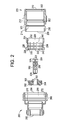
- a combination of a corrugated coaxial cable and the coaxial connector described above comprising a center conductor, a dielectric layer surrounding the center conductor, an outer corrugated conductor surrounding the dielectric layer, and a jacket surrounding the outer corrugated conductor.
- the corrugated coaxial cable 100 includes center conductor 105, dielectric 120, corrugated outer conductor 125 and jacket 130.
- Center conductor 105 is preferably annular and has an inside diameter 110 and outside diameter 115.
- Corrugated coaxial cable connector 200 is preferable preassembled in a factory and includes a rear subassembly 202 and a front subassembly 204.
- the subassemblies 202, 204 are preferably attached to one another so that they can be shipped from the factory to the field as described in more detail below.
- the rear subassembly 202 includes a rear outer body 206 having a front end 208, a backend 210, an external gripping portion 212 and a longitudinal opening 214 extending between the front end 208 and the back end 210 along the longitudinal axis A.
- the rear outer body 206 preferably includes a threaded portion 216 adjacent the front end 208 for threadingly engaging the front subassembly 204.
- Rear outer body 206 is preferably made from a metallic material such as brass and is preferable plated with a conductive, corrosion resistant material such as a nickel-tin alloy.
- the rear subassembly 202 also includes a clamping member 220, which is preferably made from a plastic material such as acetal, but may be made from a metallic material such as brass and plated with a conductive, corrosion resistant material such as a nickel-tin alloy.
- Clamping member 220 is secured within the longitudinal opening 214 of rear outer body 206 by way of a free-rotating snap fit.
- the clamping member 220 is secured in the rear outer body 206 in the factory.
- Clamping member 220 has a front end 222, a back end 224, and a longitudinal opening 226.
- the clamping member 220 has a chamfered portion 228 leading to a first inwardly projecting protrusion 230 on the internal surface 232 of the longitudinal opening 226.
- a second inwardly projecting protrusion 234 is also present on the internal surface 232, disposed rearwardly from the first inwardly projecting protrusion 230.
- the inwardly projecting protrusions 230, 234 are annular protrusions and extend around the longitudinal opening 226. However, they may also be segmented or non-continuous and still be within the scope of the present invention.
- the inwardly projecting protrusions 230, 234 engage the corrugated outer conductor 125 where the corrugated outer conductor 125 has the smallest diameter, i.e., the valleys of the corrugated outer conductor 125.
- the front end 222 of clamping member 220 preferably has a plurality of slots 240, resulting in the front end 222 having a plurality of fingers or flexible beams 242. The presence of the flexible beams allows the clamping member 220 to slide over the corrugated coaxial cable 100, and in particular, the corrugated outer conductor 125.
- the front subassembly 204 includes front body 260, insulator 300, and contact element 320.
- the front body 260 has a front end 262, a back end 264, an external gripping portion 266, and a longitudinal opening 268 extending between the front end 262 and the back end 264 along the longitudinal axis A.
- the front body 260 also has a radiused annular shoulder 270 and internal threaded portion 272. As discussed in more detail below, the radiused annular shoulder 270 cooperates with the chamfered portion 228 of the clamping member 220 to capture the corrugated outer conductor 125 to secure the connector 200 to the coaxial cable 100.
- Front body 260 is preferably made from a metallic material such as brass and is preferable plated with a conductive, corrosion resistant material such as a nickel-tin alloy.
- Insulator 300 includes a bore 302 aligned on longitudinal axis A and an outer surface 284. Insulator 300 is made from an electrically insulative material such as acetal and assists in centering and supporting contact element 320.
- Contact element 320 has a back end 322 that includes a tapered portion 324 that engages center conductor 105.
- Contact element 320 also preferably has a plurality of slots 326 at the back end 322 to allow the contact element 320 to flex as necessary to make physical and electrical contact with the central conductor 105.
- Contact element 320 is made from a metallic material such as beryllium copper, is preferably heat treated and is preferably plated with a conductive, corrosion resistant material such as a nickel-tin alloy.
- Contact element 320 has a front end 328 that has a female configuration to receive a male configured contact (not shown). However, the front end 328 of contact element 320 may also have a male configuration.
- a plurality of seals are also factory installed in the connector 200 to make it water proof.
- seals 350, 360 and 370 have been installed as illustrated in Fig. 1 .
- Seal 350 has been installed in an annular cut-out 352 at the back end 210 of the rear outer body 206. Seal 350 assists in making the connector 200 water-proof by engaging the jacket 130 of the coaxial cable 100 (see Fig. 3 ).
- Seal 360 is installed in an annular cut-out 362 in a medial portion of the rear outer body 206 and seals the junction between the clamping member 220 and the rear outer body 206.
- Seal 370 has been installed on the outer surface of the rear outer body 206 in an annular cut-out 372 and, as noted below in conjunction with FIG. 5 , seals the junction of the rear outer body 206 and the front body 260 when the connector is assembled on the corrugated coaxial cable 100.
- Two seals 380, 390 are also factory-installed in the front subassembly 204 to seal the connector 200 from the front.
- Seal 380 has been installed in an annular cut-out 382 on contact element 320 to seal the connector 200 when the contact element 320 is installed in insulator 300.
- seal 390 is factory-installed in an annular cut-out 392 in insulator 300 to seal the junction between the insulator 300 and the front body 260.
- FIG. 3 the installation of the corrugated coaxial cable connector 200 will now be described. If not already separated from one another, the rear subassembly 202 and front subassembly 204 should be separated from one another, i.e., unscrewed from one another in a preferred embodiment.
- the rear subassembly 202 is then placed over the corrugated coaxial cable 100, the corrugated coaxial cable 100 having the jacket 130 stripped back to expose a portion of the corrugated outer conductor 125.
- the clamping member 220 slides over the corrugated coaxial cable 100, and in particular, the corrugated outer conductor 125 with the plurality of fingers or flexible beams 242 flexing sufficiently to allow the rear subassembly 202 to slide on the corrugated coaxial cable 100.
- the rear subassembly 202 should naturally rest with the first inwardly projecting protrusion 230 on the internal surface 232 of the longitudinal opening 226 of clamping member 220 in an annular groove of the corrugated outer conductor 125.
- the second inwardly projecting protrusion 234 will also be in an annular groove of the corrugated outer conductor 125 and the seal 350 will engage the cable jacket 130.
- the front subassembly 204 is partially installed on the rear subassembly 202, which in this embodiment is done by rotating the rear subassembly 202 and front subassembly 204 relative to one another.
- the contact element 320 is aligned with and engages the inside diameter 110 of the center conductor 105.
- the tapered portion 324 assures that the contact element 320 will make physical and electrical contact with the center conductor 105.
- the slots 326 allow the contact element 320 to radially compress to fit within the center conductor 105.
- the radiused annular shoulder 270 moves between the corrugated outer conductor 125 and the dielectric 120 to pinch the corrugated outer conductor 125 between the radiused annular shoulder 270 and the chamfered portion 228 of the clamping member 220.
- the rear subassembly 202 is fully tightened into front subassembly 204 by further rotation of internal threaded portion 272 of front body 260 and external threaded portion 219 of rear body 206. It should be noted that the rotational engagement of front body 260 to rear body 206 does not transmit appreciable rotational or torsional load to clamping member 220 as it is a separate member (as well as a free rotating member), thus preventing damage to flexible beams 242 of clamping member 220.
- first inwardly projecting protrusion 230 and second inwardly projecting protrusion 234 contact the corrugated outer conductor 125 at circumferential points B and C, respectively, and corrugated outer conductor 125 is captured between the radiused annular shoulder 270 and the chamfered portion 228 of the clamping member 220 providing positive electrical and mechanical communication between corrugated outer conductor 125 and front body 260.
- Second inwardly projecting protrusion 234 contacts corrugated outer conductor 125 at circumferential point C and provides additional axial load as well as radial support thus further stabilizing the connector/cable junction.
- the additional radial support by the second inwardly projecting protrusion 234 is especially helpful to provide strain relief and ensure long term electrical and mechanical stability of the junction.
- Tertiary circumferential points of support for cable 100 are provided by seals 350 and 360, particularly since seal 360 is deformed inwardly by the connection of front body 260 to rear outer body 206.
- Corrugated coaxial cable connector 600 is similar to the first embodiment and has a rear outer body 606, a clamping member 620, a front body 660, insulator 700, and contact 720.
- the corrugated coaxial cable connector 600 also has the same seals, but clamping member 620 has an additional inwardly projecting annular projection 650 at the rear end thereof to engage the corrugated outer conductor 125 and provide a full 360 degree band of support for coaxial cable 100.
Landscapes
- Coupling Device And Connection With Printed Circuit (AREA)
Claims (7)
- Koaxialkabel-Steckverbinder zur Anbringung an ein gewelltes Koaxialkabel, wobei das Koaxialkabel einen Mittelleiter, eine dielektrische, den Mittelleiter umgebende, Schicht und einen äußeren gewellten Leiter umfasst, der die dielektrische Schicht umgibt, wobei der koaxiale Kabelsteckverbinder umfasst:einen hinteren Außenkörper (206) mit einem vorderen Ende, einem hinteren Ende, einem externen Griffteil und einer a longitudinalen Öffnung, die sich zwischen dem vorderen Ende und dem hinteren Ende entlang einer Längsachse erstreckt;ein Klemmelement (220), das innerhalb der longitudinalen Öffnung im hinteren Außenkörper (206) ab dem vorderen Ende davon angeordnet ist, wobei das Klemmelement (220) eine Vielzahl flexibler Träger (242) einschließt;einen vorderen Körper (204) mit einem vorderen Ende, einem hinteren Ende, einem externen Griffteil und einer a longitudinalen Öffnung, die sich zwischen dem vorderen Ende und dem hinteren Ende entlang einer Längsachse erstreckt; undeinen Isolator (300), der im vorderen Körper (204) angeordnet ist, wobei der Isolator (300) eine Öffnung darin koaxial mit der Längsachse des vorderen Körpers aufweist,wobei der Steckverbinder ferner ein Kontaktelement (320) umfasst, das in der Öffnung des Isolators (300) angeordnet ist,und wobei das Klemmelement drehbar an die longitudinale Öffnung im hinteren Außenkörper (206) mittels eines sich frei drehenden Schnappverschlusses montiert ist;dadurch gekennzeichnet, dass das Kontaktelement (320) ein hinteres Ende aufweist, dass einen verjüngten Teil (324) aufweist, der konfiguriert ist, den Mittelleiter des gewellten Koaxialkabels in Eingriff zu bringen,und dadurch, dass wenigstens einer der Vielzahl flexibler Träger (242) einer Innenfläche (232) mit wenigstens zwei Vorsprüngen (230, 234) aufweist, die konfiguriert sind, den äußeren gewellten Leiter in Eingriff zu bringen, wo der gewellte Leiter einen Durchmesser aufweist, welcher der Kleinste ist.
- Koaxialkabel-Steckverbinder nach Anspruch 1, wobei die wenigstens zwei Vorsprünge (230, 234) radial nach innen vorspringende kreisförmige Ringe umfassen.
- Koaxialkabel-Steckverbinder nach Anspruch 1, wobei die wenigstens zwei Vorsprünge drei Vorsprünge (230, 234, 650) umfassen.
- Koaxialkabel-Steckverbinder nach Anspruch 1, der ferner wenigstens zwei Dichtungen (350, 360) umfasst, die, wenn völlig installiert, konfiguriert sind, das gewellte Koaxialkabel in Eingriff zu bringen.
- Kombination eines gewellten Koaxialkabels (100) und eines koaxialen Steckverbinders (200), wobei das Koaxialkabel einen Mittelleiter (105), eine den Mittelleiter (105) umgebende dielektrische Schicht (120), einen äußeren gewellten Leiter (125), der die dielektrische Schicht (120) umgibt und einen Mantel (130) umfasst, der den äußeren gewellten Leiter (125) umgibt, wobei der Steckverbinder (200) der Koaxialkabel-Steckverbinder gemäß einem vorhergehenden Anspruch ist.
- Kombination nach Anspruch 5, wobei der Mittelleiter des Koaxialkabels hohl ist und eine Innenfläche aufweist und das Kontaktelement (320) angepasst ist, physikalischen und elektrischen Kontakt mit der Innenfläche des Mittelleiters herzustellen.
- Kombination nach Anspruch 5, wenn von Anspruch 4 abhängig, wobei wenigstens eine der wenigstens zwei Dichtungen (350, 360) in den Mantel (130) eingreift und wenigstens eine der wenigstens zwei Dichtungen (350, 360) in den äußeren gewellten Leiter (125) des gewellten Koaxialkabels eingreift.
Applications Claiming Priority (1)
| Application Number | Priority Date | Filing Date | Title |
|---|---|---|---|
| US401107P | 2007-11-21 | 2007-11-21 |
Publications (2)
| Publication Number | Publication Date |
|---|---|
| EP2063501A1 EP2063501A1 (de) | 2009-05-27 |
| EP2063501B1 true EP2063501B1 (de) | 2016-10-05 |
Family
ID=39745218
Family Applications (1)
| Application Number | Title | Priority Date | Filing Date |
|---|---|---|---|
| EP08162022.1A Active EP2063501B1 (de) | 2007-11-21 | 2008-08-07 | Koaxialkabelstecker für geriffeltes Kabel |
Country Status (7)
| Country | Link |
|---|---|
| US (1) | US7690945B2 (de) |
| EP (1) | EP2063501B1 (de) |
| CN (1) | CN101919126B (de) |
| DK (1) | DK2063501T3 (de) |
| PL (1) | PL2063501T3 (de) |
| TW (1) | TWI389400B (de) |
| WO (1) | WO2009067132A1 (de) |
Families Citing this family (15)
| Publication number | Priority date | Publication date | Assignee | Title |
|---|---|---|---|---|
| US8460031B2 (en) * | 2008-11-05 | 2013-06-11 | Andrew Llc | Coaxial connector with cable diameter adapting seal assembly and interconnection method |
| US7803018B1 (en) * | 2009-03-10 | 2010-09-28 | Andrew Llc | Inner conductor end contacting coaxial connector and inner conductor adapter kit |
| BRPI1015106A2 (pt) * | 2009-06-05 | 2016-04-26 | Andrew Llc | conector coaxial de agarre e sujeição. |
| US20110117777A1 (en) * | 2009-11-16 | 2011-05-19 | Thomas & Betts International, Inc. | Cable connector |
| US9166306B2 (en) | 2010-04-02 | 2015-10-20 | John Mezzalingua Associates, LLC | Method of terminating a coaxial cable |
| US7934954B1 (en) | 2010-04-02 | 2011-05-03 | John Mezzalingua Associates, Inc. | Coaxial cable compression connectors |
| US8177582B2 (en) | 2010-04-02 | 2012-05-15 | John Mezzalingua Associates, Inc. | Impedance management in coaxial cable terminations |
| US8468688B2 (en) | 2010-04-02 | 2013-06-25 | John Mezzalingua Associates, LLC | Coaxial cable preparation tools |
| WO2011146441A1 (en) * | 2010-05-19 | 2011-11-24 | Corning Gilbert Inc. | Coaxial connector for corrugated cable with integral clamping and sealing member |
| DE202010011857U1 (de) * | 2010-08-25 | 2010-10-28 | Ccs Cable Connector Systems Gmbh | Stecker, insbesondere Photovoltaikstecker |
| DE102010037193A1 (de) * | 2010-08-27 | 2012-03-01 | Phoenix Contact Gmbh & Co. Kg | Kabelzugentlastung |
| US8657626B2 (en) * | 2010-12-02 | 2014-02-25 | Thomas & Betts International, Inc. | Cable connector with retaining element |
| CN103794899A (zh) * | 2012-10-26 | 2014-05-14 | 江苏正恺电子科技有限公司 | 中心导体突变的射频连接器 |
| CN109904687B (zh) * | 2019-02-18 | 2020-09-08 | 苏州华旃航天电器有限公司 | 新型耐高温、高压水汽密封n-k型端接电缆射频同轴连接器 |
| EP4275251A4 (de) * | 2021-01-08 | 2024-11-13 | Corning Optical Communications RF LLC | Koaxialverbinderanordnung mit verriegelungshülse |
Family Cites Families (29)
| Publication number | Priority date | Publication date | Assignee | Title |
|---|---|---|---|---|
| US3199061A (en) | 1963-01-31 | 1965-08-03 | Andrew Corp | Coaxial connector |
| US3291895A (en) | 1964-05-05 | 1966-12-13 | Andrew Corp | Coaxial cable connectors |
| US4046451A (en) | 1976-07-08 | 1977-09-06 | Andrew Corporation | Connector for coaxial cable with annularly corrugated outer conductor |
| DE3422549A1 (de) * | 1984-06-18 | 1985-12-19 | Georg Dr.-Ing. 8152 Feldkirchen-Westerham Spinner | Stecker fuer koaxialkabel |
| US5154636A (en) | 1991-01-15 | 1992-10-13 | Andrew Corporation | Self-flaring connector for coaxial cable having a helically corrugated outer conductor |
| US5137470A (en) | 1991-06-04 | 1992-08-11 | Andrew Corporation | Connector for coaxial cable having a helically corrugated inner conductor |
| FR2682819B1 (fr) | 1991-10-21 | 1994-09-30 | Signal Engineering Electronics | Connecteur pour cables coaxiaux. |
| US5167533A (en) | 1992-01-08 | 1992-12-01 | Andrew Corporation | Connector for coaxial cable having hollow inner conductors |
| DE4207482C1 (en) | 1992-03-10 | 1993-07-08 | Wilhelm Sihn Jun. Kg, 7532 Niefern-Oeschelbronn, De | Forming flanged rim in waveguide of coaxial cable - allowing armature to be mounted with bearing clamped to fit in troughs of waveguide pushed to abut bearing |
| DE4309775C2 (de) | 1993-03-25 | 1995-08-17 | Spinner Gmbh Elektrotech | Steckverbinder für Koaxialkabel mit Wellrohraußenleiter |
| US5435745A (en) | 1994-05-31 | 1995-07-25 | Andrew Corporation | Connector for coaxial cable having corrugated outer conductor |
| DE19738733C1 (de) | 1997-09-04 | 1999-06-17 | Spinner Gmbh Elektrotech | Steckverbinder für Koaxialkabel mit ringgewelltem Außenleiter |
| US6109964A (en) | 1998-04-06 | 2000-08-29 | Andrew Corporation | One piece connector for a coaxial cable with an annularly corrugated outer conductor |
| EP0975051A1 (de) | 1998-07-24 | 2000-01-26 | Cabel-Con A/S | Steckverbinder für Koaxialkabel mit einem Mehrganggewinde |
| DE19846440A1 (de) | 1998-10-08 | 2000-04-20 | Spinner Gmbh Elektrotech | Steckverbinder für Koaxialkabel mit ringgewelltem Außenleiter |
| DE19857528C2 (de) | 1998-12-14 | 2002-06-20 | Spinner Gmbh Elektrotech | Steckverbinder für Koaxialkabel mit ringgewelltem Außenleiter |
| US6332808B1 (en) * | 1999-09-22 | 2001-12-25 | Mitsubishi Cable Industries, Ltd. | Connector structure |
| EP1122835A1 (de) | 2000-02-04 | 2001-08-08 | Cabel-Con A/S | Einstückiger Verbinder |
| EP1148592A1 (de) | 2000-04-17 | 2001-10-24 | Cabel-Con A/S | Steckverbinder für Koaxialkabel mit ringgewelltem Aussenleiter |
| EP1170833A1 (de) | 2000-07-07 | 2002-01-09 | Cabel-Con A/S | Verbinder für Koaxialkabel mit einem schraubenförmigen gewellten Aussenleiter |
| US6824415B2 (en) | 2001-11-01 | 2004-11-30 | Andrew Corporation | Coaxial connector with spring loaded coupling mechanism |
| EP1376773B1 (de) * | 2002-06-22 | 2006-08-16 | Spinner GmbH | Koaxialer Steckverbinder |
| US7134189B2 (en) | 2002-09-12 | 2006-11-14 | Andrew Corporation | Coaxial cable connector and tool and method for connecting a coaxial cable |
| US6840803B2 (en) | 2003-02-13 | 2005-01-11 | Andrew Corporation | Crimp connector for corrugated cable |
| US6994587B2 (en) | 2003-07-23 | 2006-02-07 | Andrew Corporation | Coaxial cable connector installable with common tools |
| US7249969B2 (en) | 2003-07-28 | 2007-07-31 | Andrew Corporation | Connector with corrugated cable interface insert |
| US7217154B2 (en) | 2005-10-19 | 2007-05-15 | Andrew Corporation | Connector with outer conductor axial compression connection and method of manufacture |
| US7275957B1 (en) | 2006-03-22 | 2007-10-02 | Andrew Corporation | Axial compression electrical connector for annular corrugated coaxial cable |
| US7189114B1 (en) | 2006-06-29 | 2007-03-13 | Corning Gilbert Inc. | Compression connector |
-
2008
- 2008-07-25 WO PCT/US2008/009031 patent/WO2009067132A1/en not_active Ceased
- 2008-07-25 CN CN2008801241188A patent/CN101919126B/zh not_active Expired - Fee Related
- 2008-08-07 EP EP08162022.1A patent/EP2063501B1/de active Active
- 2008-08-07 DK DK08162022.1T patent/DK2063501T3/en active
- 2008-08-07 PL PL08162022T patent/PL2063501T3/pl unknown
- 2008-11-05 US US12/265,286 patent/US7690945B2/en active Active
- 2008-11-18 TW TW097144612A patent/TWI389400B/zh not_active IP Right Cessation
Also Published As
| Publication number | Publication date |
|---|---|
| CN101919126A (zh) | 2010-12-15 |
| US7690945B2 (en) | 2010-04-06 |
| TWI389400B (zh) | 2013-03-11 |
| WO2009067132A1 (en) | 2009-05-28 |
| PL2063501T3 (pl) | 2017-02-28 |
| EP2063501A1 (de) | 2009-05-27 |
| US20090130900A1 (en) | 2009-05-21 |
| DK2063501T3 (en) | 2016-11-14 |
| CN101919126B (zh) | 2013-10-23 |
| TW200939580A (en) | 2009-09-16 |
Similar Documents
| Publication | Publication Date | Title |
|---|---|---|
| EP2063501B1 (de) | Koaxialkabelstecker für geriffeltes Kabel | |
| EP1668744B1 (de) | Coaxialverbinder mit verbessertem isolationsglied und assoziiertes verfahren | |
| US4668043A (en) | Solderless connectors for semi-rigid coaxial cable | |
| EP1686660B1 (de) | Gegenüber der Umgebung abgedichteter selbstzentrierender Verbinder | |
| US7297023B2 (en) | Coaxial cable connector with improved weather seal | |
| US6109964A (en) | One piece connector for a coaxial cable with an annularly corrugated outer conductor | |
| EP2382691B1 (de) | Koaxialverbinder für geriffeltes kabel | |
| EP2254199A1 (de) | Abgeschirmtes Kabelende für eine elektrische Steckvorrichtung | |
| US11024989B2 (en) | Coaxial cable connectors having an integrated biasing feature | |
| CN110521075B (zh) | 用于保持屏蔽电缆的保持设备 | |
| US5358433A (en) | Female electrical contact terminal for a connector | |
| US11824314B2 (en) | Push-on coaxial cable connectors having port grounding | |
| US9033730B2 (en) | Coaxial cable connector and method of making same | |
| CA2446276C (en) | Waterproof connector which can be improved in assembling workability | |
| US20230010610A1 (en) | Coaxial cable and connector assemblies and methods of assembling same | |
| CN116613571A (zh) | 防水射频同轴连接器 | |
| US5498179A (en) | Electrical connector | |
| WO2011146441A1 (en) | Coaxial connector for corrugated cable with integral clamping and sealing member | |
| CN110504581B (zh) | 一种连接器及电缆组件 | |
| US20210167563A1 (en) | Coaxial cable assemblies having pinching and gripping elements | |
| CA1216910A (en) | Solderless connectors for semi-rigid coaxial cable | |
| US9647384B2 (en) | Back body for coaxial connector | |
| US20230291156A1 (en) | Enhanced connector post for maintaining a ground path | |
| HK1090178B (en) | Coaxial connector with enhanced insulator member and associated method |
Legal Events
| Date | Code | Title | Description |
|---|---|---|---|
| PUAI | Public reference made under article 153(3) epc to a published international application that has entered the european phase |
Free format text: ORIGINAL CODE: 0009012 |
|
| AK | Designated contracting states |
Kind code of ref document: A1 Designated state(s): AT BE BG CH CY CZ DE DK EE ES FI FR GB GR HR HU IE IS IT LI LT LU LV MC MT NL NO PL PT RO SE SI SK TR |
|
| AX | Request for extension of the european patent |
Extension state: AL BA MK RS |
|
| 17P | Request for examination filed |
Effective date: 20091118 |
|
| AKX | Designation fees paid |
Designated state(s): AT BE BG CH CY CZ DE DK EE ES FI FR GB GR HR HU IE IS IT LI LT LU LV MC MT NL NO PL PT RO SE SI SK TR |
|
| 17Q | First examination report despatched |
Effective date: 20100118 |
|
| GRAP | Despatch of communication of intention to grant a patent |
Free format text: ORIGINAL CODE: EPIDOSNIGR1 |
|
| INTG | Intention to grant announced |
Effective date: 20160530 |
|
| GRAS | Grant fee paid |
Free format text: ORIGINAL CODE: EPIDOSNIGR3 |
|
| GRAA | (expected) grant |
Free format text: ORIGINAL CODE: 0009210 |
|
| AK | Designated contracting states |
Kind code of ref document: B1 Designated state(s): AT BE BG CH CY CZ DE DK EE ES FI FR GB GR HR HU IE IS IT LI LT LU LV MC MT NL NO PL PT RO SE SI SK TR |
|
| REG | Reference to a national code |
Ref country code: GB Ref legal event code: FG4D |
|
| REG | Reference to a national code |
Ref country code: CH Ref legal event code: EP |
|
| REG | Reference to a national code |
Ref country code: AT Ref legal event code: REF Ref document number: 835349 Country of ref document: AT Kind code of ref document: T Effective date: 20161015 |
|
| REG | Reference to a national code |
Ref country code: NL Ref legal event code: FP |
|
| REG | Reference to a national code |
Ref country code: IE Ref legal event code: FG4D |
|
| REG | Reference to a national code |
Ref country code: DK Ref legal event code: T3 Effective date: 20161110 |
|
| REG | Reference to a national code |
Ref country code: DE Ref legal event code: R096 Ref document number: 602008046616 Country of ref document: DE |
|
| REG | Reference to a national code |
Ref country code: LT Ref legal event code: MG4D |
|
| PG25 | Lapsed in a contracting state [announced via postgrant information from national office to epo] |
Ref country code: LV Free format text: LAPSE BECAUSE OF FAILURE TO SUBMIT A TRANSLATION OF THE DESCRIPTION OR TO PAY THE FEE WITHIN THE PRESCRIBED TIME-LIMIT Effective date: 20161005 |
|
| REG | Reference to a national code |
Ref country code: AT Ref legal event code: MK05 Ref document number: 835349 Country of ref document: AT Kind code of ref document: T Effective date: 20161005 |
|
| PG25 | Lapsed in a contracting state [announced via postgrant information from national office to epo] |
Ref country code: SE Free format text: LAPSE BECAUSE OF FAILURE TO SUBMIT A TRANSLATION OF THE DESCRIPTION OR TO PAY THE FEE WITHIN THE PRESCRIBED TIME-LIMIT Effective date: 20161005 Ref country code: NO Free format text: LAPSE BECAUSE OF FAILURE TO SUBMIT A TRANSLATION OF THE DESCRIPTION OR TO PAY THE FEE WITHIN THE PRESCRIBED TIME-LIMIT Effective date: 20170105 Ref country code: GR Free format text: LAPSE BECAUSE OF FAILURE TO SUBMIT A TRANSLATION OF THE DESCRIPTION OR TO PAY THE FEE WITHIN THE PRESCRIBED TIME-LIMIT Effective date: 20170106 Ref country code: LT Free format text: LAPSE BECAUSE OF FAILURE TO SUBMIT A TRANSLATION OF THE DESCRIPTION OR TO PAY THE FEE WITHIN THE PRESCRIBED TIME-LIMIT Effective date: 20161005 |
|
| PG25 | Lapsed in a contracting state [announced via postgrant information from national office to epo] |
Ref country code: BE Free format text: LAPSE BECAUSE OF FAILURE TO SUBMIT A TRANSLATION OF THE DESCRIPTION OR TO PAY THE FEE WITHIN THE PRESCRIBED TIME-LIMIT Effective date: 20161005 Ref country code: ES Free format text: LAPSE BECAUSE OF FAILURE TO SUBMIT A TRANSLATION OF THE DESCRIPTION OR TO PAY THE FEE WITHIN THE PRESCRIBED TIME-LIMIT Effective date: 20161005 Ref country code: PT Free format text: LAPSE BECAUSE OF FAILURE TO SUBMIT A TRANSLATION OF THE DESCRIPTION OR TO PAY THE FEE WITHIN THE PRESCRIBED TIME-LIMIT Effective date: 20170206 Ref country code: AT Free format text: LAPSE BECAUSE OF FAILURE TO SUBMIT A TRANSLATION OF THE DESCRIPTION OR TO PAY THE FEE WITHIN THE PRESCRIBED TIME-LIMIT Effective date: 20161005 Ref country code: IS Free format text: LAPSE BECAUSE OF FAILURE TO SUBMIT A TRANSLATION OF THE DESCRIPTION OR TO PAY THE FEE WITHIN THE PRESCRIBED TIME-LIMIT Effective date: 20170205 Ref country code: HR Free format text: LAPSE BECAUSE OF FAILURE TO SUBMIT A TRANSLATION OF THE DESCRIPTION OR TO PAY THE FEE WITHIN THE PRESCRIBED TIME-LIMIT Effective date: 20161005 Ref country code: FI Free format text: LAPSE BECAUSE OF FAILURE TO SUBMIT A TRANSLATION OF THE DESCRIPTION OR TO PAY THE FEE WITHIN THE PRESCRIBED TIME-LIMIT Effective date: 20161005 |
|
| REG | Reference to a national code |
Ref country code: DE Ref legal event code: R097 Ref document number: 602008046616 Country of ref document: DE |
|
| PG25 | Lapsed in a contracting state [announced via postgrant information from national office to epo] |
Ref country code: RO Free format text: LAPSE BECAUSE OF FAILURE TO SUBMIT A TRANSLATION OF THE DESCRIPTION OR TO PAY THE FEE WITHIN THE PRESCRIBED TIME-LIMIT Effective date: 20161005 Ref country code: CZ Free format text: LAPSE BECAUSE OF FAILURE TO SUBMIT A TRANSLATION OF THE DESCRIPTION OR TO PAY THE FEE WITHIN THE PRESCRIBED TIME-LIMIT Effective date: 20161005 Ref country code: EE Free format text: LAPSE BECAUSE OF FAILURE TO SUBMIT A TRANSLATION OF THE DESCRIPTION OR TO PAY THE FEE WITHIN THE PRESCRIBED TIME-LIMIT Effective date: 20161005 Ref country code: SK Free format text: LAPSE BECAUSE OF FAILURE TO SUBMIT A TRANSLATION OF THE DESCRIPTION OR TO PAY THE FEE WITHIN THE PRESCRIBED TIME-LIMIT Effective date: 20161005 |
|
| PLBE | No opposition filed within time limit |
Free format text: ORIGINAL CODE: 0009261 |
|
| STAA | Information on the status of an ep patent application or granted ep patent |
Free format text: STATUS: NO OPPOSITION FILED WITHIN TIME LIMIT |
|
| PG25 | Lapsed in a contracting state [announced via postgrant information from national office to epo] |
Ref country code: BG Free format text: LAPSE BECAUSE OF FAILURE TO SUBMIT A TRANSLATION OF THE DESCRIPTION OR TO PAY THE FEE WITHIN THE PRESCRIBED TIME-LIMIT Effective date: 20170105 Ref country code: IT Free format text: LAPSE BECAUSE OF FAILURE TO SUBMIT A TRANSLATION OF THE DESCRIPTION OR TO PAY THE FEE WITHIN THE PRESCRIBED TIME-LIMIT Effective date: 20161005 |
|
| 26N | No opposition filed |
Effective date: 20170706 |
|
| PG25 | Lapsed in a contracting state [announced via postgrant information from national office to epo] |
Ref country code: SI Free format text: LAPSE BECAUSE OF FAILURE TO SUBMIT A TRANSLATION OF THE DESCRIPTION OR TO PAY THE FEE WITHIN THE PRESCRIBED TIME-LIMIT Effective date: 20161005 |
|
| REG | Reference to a national code |
Ref country code: CH Ref legal event code: PL |
|
| PG25 | Lapsed in a contracting state [announced via postgrant information from national office to epo] |
Ref country code: MC Free format text: LAPSE BECAUSE OF FAILURE TO SUBMIT A TRANSLATION OF THE DESCRIPTION OR TO PAY THE FEE WITHIN THE PRESCRIBED TIME-LIMIT Effective date: 20161005 |
|
| PG25 | Lapsed in a contracting state [announced via postgrant information from national office to epo] |
Ref country code: LI Free format text: LAPSE BECAUSE OF NON-PAYMENT OF DUE FEES Effective date: 20170831 Ref country code: CH Free format text: LAPSE BECAUSE OF NON-PAYMENT OF DUE FEES Effective date: 20170831 |
|
| REG | Reference to a national code |
Ref country code: FR Ref legal event code: ST Effective date: 20180430 |
|
| REG | Reference to a national code |
Ref country code: IE Ref legal event code: MM4A |
|
| PG25 | Lapsed in a contracting state [announced via postgrant information from national office to epo] |
Ref country code: LU Free format text: LAPSE BECAUSE OF NON-PAYMENT OF DUE FEES Effective date: 20170807 |
|
| PG25 | Lapsed in a contracting state [announced via postgrant information from national office to epo] |
Ref country code: IE Free format text: LAPSE BECAUSE OF NON-PAYMENT OF DUE FEES Effective date: 20170807 |
|
| PG25 | Lapsed in a contracting state [announced via postgrant information from national office to epo] |
Ref country code: FR Free format text: LAPSE BECAUSE OF NON-PAYMENT OF DUE FEES Effective date: 20170831 |
|
| PG25 | Lapsed in a contracting state [announced via postgrant information from national office to epo] |
Ref country code: MT Free format text: LAPSE BECAUSE OF NON-PAYMENT OF DUE FEES Effective date: 20170807 |
|
| PG25 | Lapsed in a contracting state [announced via postgrant information from national office to epo] |
Ref country code: HU Free format text: LAPSE BECAUSE OF FAILURE TO SUBMIT A TRANSLATION OF THE DESCRIPTION OR TO PAY THE FEE WITHIN THE PRESCRIBED TIME-LIMIT; INVALID AB INITIO Effective date: 20080807 |
|
| PGFP | Annual fee paid to national office [announced via postgrant information from national office to epo] |
Ref country code: NL Payment date: 20190730 Year of fee payment: 12 |
|
| PG25 | Lapsed in a contracting state [announced via postgrant information from national office to epo] |
Ref country code: CY Free format text: LAPSE BECAUSE OF NON-PAYMENT OF DUE FEES Effective date: 20161005 |
|
| PG25 | Lapsed in a contracting state [announced via postgrant information from national office to epo] |
Ref country code: TR Free format text: LAPSE BECAUSE OF FAILURE TO SUBMIT A TRANSLATION OF THE DESCRIPTION OR TO PAY THE FEE WITHIN THE PRESCRIBED TIME-LIMIT Effective date: 20161005 |
|
| REG | Reference to a national code |
Ref country code: DE Ref legal event code: R082 Ref document number: 602008046616 Country of ref document: DE Representative=s name: HERNANDEZ, YORCK, DIPL.-ING., DE Ref country code: DE Ref legal event code: R081 Ref document number: 602008046616 Country of ref document: DE Owner name: CORNING OPTICAL COMMUNICATIONS RF LLC, GLENDAL, US Free format text: FORMER OWNER: CORNING GILBERT INC., GLENDALE, ARIZ., US Ref country code: DE Ref legal event code: R081 Ref document number: 602008046616 Country of ref document: DE Owner name: CORNING OPTICAL COMMUNICATIONS APS, DK Free format text: FORMER OWNER: CORNING GILBERT INC., GLENDALE, ARIZ., US |
|
| REG | Reference to a national code |
Ref country code: DE Ref legal event code: R082 Ref document number: 602008046616 Country of ref document: DE Representative=s name: HERNANDEZ, YORCK, DIPL.-ING., DE Ref country code: DE Ref legal event code: R081 Ref document number: 602008046616 Country of ref document: DE Owner name: CORNING OPTICAL COMMUNICATIONS APS, DK Free format text: FORMER OWNER: CORNING OPTICAL COMMUNICATIONS RF LLC, GLENDALE, ARIZ., US |
|
| REG | Reference to a national code |
Ref country code: NL Ref legal event code: MM Effective date: 20200901 |
|
| REG | Reference to a national code |
Ref country code: GB Ref legal event code: 732E Free format text: REGISTERED BETWEEN 20210527 AND 20210602 |
|
| PG25 | Lapsed in a contracting state [announced via postgrant information from national office to epo] |
Ref country code: NL Free format text: LAPSE BECAUSE OF NON-PAYMENT OF DUE FEES Effective date: 20200901 |
|
| P01 | Opt-out of the competence of the unified patent court (upc) registered |
Effective date: 20230601 |
|
| PGFP | Annual fee paid to national office [announced via postgrant information from national office to epo] |
Ref country code: PL Payment date: 20250606 Year of fee payment: 18 |
|
| PGFP | Annual fee paid to national office [announced via postgrant information from national office to epo] |
Ref country code: GB Payment date: 20250619 Year of fee payment: 18 |
|
| PGFP | Annual fee paid to national office [announced via postgrant information from national office to epo] |
Ref country code: DK Payment date: 20250814 Year of fee payment: 18 Ref country code: DE Payment date: 20250611 Year of fee payment: 18 |