EP2063279B1 - Spannungserkennungsvorrichtung für Batteriemodule - Google Patents
Spannungserkennungsvorrichtung für Batteriemodule Download PDFInfo
- Publication number
- EP2063279B1 EP2063279B1 EP08169628.8A EP08169628A EP2063279B1 EP 2063279 B1 EP2063279 B1 EP 2063279B1 EP 08169628 A EP08169628 A EP 08169628A EP 2063279 B1 EP2063279 B1 EP 2063279B1
- Authority
- EP
- European Patent Office
- Prior art keywords
- battery
- battery modules
- capacitor
- voltage
- circuit
- Prior art date
- Legal status (The legal status is an assumption and is not a legal conclusion. Google has not performed a legal analysis and makes no representation as to the accuracy of the status listed.)
- Expired - Fee Related
Links
Images


Classifications
-
- G—PHYSICS
- G01—MEASURING; TESTING
- G01R—MEASURING ELECTRIC VARIABLES; MEASURING MAGNETIC VARIABLES
- G01R19/00—Arrangements for measuring currents or voltages or for indicating presence or sign thereof
- G01R19/165—Indicating that current or voltage is either above or below a predetermined value or within or outside a predetermined range of values
- G01R19/16533—Indicating that current or voltage is either above or below a predetermined value or within or outside a predetermined range of values characterised by the application
- G01R19/16538—Indicating that current or voltage is either above or below a predetermined value or within or outside a predetermined range of values characterised by the application in AC or DC supplies
- G01R19/16542—Indicating that current or voltage is either above or below a predetermined value or within or outside a predetermined range of values characterised by the application in AC or DC supplies for batteries
-
- G—PHYSICS
- G01—MEASURING; TESTING
- G01R—MEASURING ELECTRIC VARIABLES; MEASURING MAGNETIC VARIABLES
- G01R31/00—Arrangements for testing electric properties; Arrangements for locating electric faults; Arrangements for electrical testing characterised by what is being tested not provided for elsewhere
- G01R31/36—Arrangements for testing, measuring or monitoring the electrical condition of accumulators or electric batteries, e.g. capacity or state of charge [SoC]
- G01R31/396—Acquisition or processing of data for testing or for monitoring individual cells or groups of cells within a battery
Definitions
- an A/D (analog to digital) converter converts an analog output signal of the differential amplifier into a digital signal
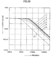
- aliasing occurs due to noise caused by frequencies higher than half a sampling frequency.
- an anti-aliasing filter is applied between the switch and a battery module to be measured so as to prevent the aliasing.
- the voltage detecting circuit of JP2005-003618A amends the difference in frequency response between the battery modules on the basis of a constant value of electronic parts
- the constant value needs to be strictly determined. If the constant value is erroneously determined, an error resulting from variance of the constant value is considerably large. For example, if a photo MOS relay having a predetermined delay time in switching is provided for a switch, a sampling frequency of switching cannot be raised due to a long delay time. Consequently, the voltage detecting device including the photo MOS relay is affected by the noise of a relatively low frequency.
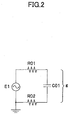
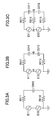
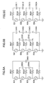
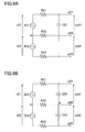
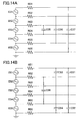
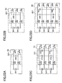
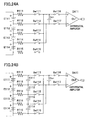
- each of two filters in FIG.3B has an equivalent frequency response of one filter in FIG.2 where one battery module is provided.
Landscapes
- Physics & Mathematics (AREA)
- General Physics & Mathematics (AREA)
- Engineering & Computer Science (AREA)
- Power Engineering (AREA)
- Secondary Cells (AREA)
- Charge And Discharge Circuits For Batteries Or The Like (AREA)
Claims (5)
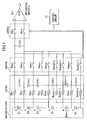
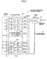
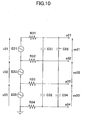
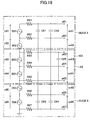
- Spannungserkennungsvorrichtung für Batteriemodule zur individuellen Erkennung einer Spannung eines Batteriemoduls einer Sekundärbatterie (11), wobei jedes Batteriemodul aus mindestens einer Zelle oder mehr besteht und M Sätze von Batteriemodulen in Reihe geschaltet sind, und "M" eine positive ganze Zahl ist, wobei die Spannungserkennungsvorrichtung für Batteriemodule Folgendes aufweist:(M+1) Sätze von Spannungserkennungsanschlüssen zum Anschluss an eine positive Elektrode eines oberen Batteriemoduls, eine negative Elektrode eines unteren Batteriemoduls, und (M-1) Sätze von Anschlussstellen zwischen den Batteriemodulen;einen Filterkreis, dessen Eingangsanschlüsse mit den Spannungserkennungsanschlüssen verbunden sind;einen Schaltkreis (14), dessen Eingangsanschlüsse mit Ausgangsanschlüssen des Filterkreises verbunden sind; sowieeinen Spannungserkennungskreis zum Anschluss an Ausgangsanschlüsse des Schaltkreises (14) und Erkennen der Spannung jedes Batteriemoduls,
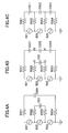
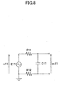
wobeider Filterkreis (12) Widerstände (R11, R12), die zwischen den Eingangsanschlüssen und den Ausgangsanschlüssen des Filterkreises angeordnet sind, und einen Kondensator aufweist, der zwischen den Anschlüssen der Widerstände (R11, R12) angeordnet ist, wodurch eine Kenngröße eines Tiefpassfilters erhalten wird, undwobei eine ganze Zahl N eine positive ganze Zahl ist, undwobei M mindestens eine von 4n, 4n+1, 4n+2 und 4n+3 ist, und eine positive ganze Zahl ist,die Widerstands-/Kondensatorkonfiguration aus (M+1) Sätzen der Widerstände (R11, R12), die einen gleichen Widerstandswert aufweisen, um einen N-ten Eingangsanschluss des Filterkreises (12) an einen N-ten Ausgangsanschluss des Filterkreises anzuschließen, und M Sätzen der Kondensatoren aufgebaut ist, deren Anschlüsse zwischen den Ausgangsanschlüssen von zwei benachbarten Widerständen (R11, R12) aus den (M+1) Sätzen von Widerständen (R11, R12) angeschlossen sind, und
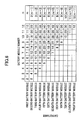
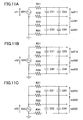
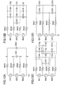
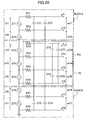
wobei, wenn die Kapazität des einem ersten Batteriemodul entsprechenden Kondensators als 1 betrachtet wird, das Kapazitätsverhältnis des einem N-ten Batteriemodul entsprechenden Kondensators als "N(M-N+1)/M" ausgedrückt wird. - Spannungserkennungsvorrichtung für Batteriemodule gemäß einem der vorhergehenden Ansprüche, wobei "M" eine positive ganze Zahl ist und ein zwischen dem M/2-ten Eingangsanschluss des Filterkreises (12) und dem M/2-ten Ausgangsanschluss des Filterkreises (12) angeschlossener Widerstand durch einen Draht ersetzt ist.
- Spannungserkennungsvorrichtung für Batteriemodule gemäß einem der vorhergehenden Ansprüche, wobei, wenn die Anzahl an Batteriemodulen als "M" ausgedrückt wird und M eine positive und ganze Zahl ist, ein zwischen den M/2-ten Eingangsanschluss des Filterkreises (12) und den M/2-ten Ausgangsanschluss des Filterkreises (12) angeschlossener Widerstand durch einen Draht ersetzt ist.
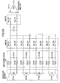
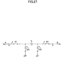
- Spannungserkennungsvorrichtung für Batteriemodule gemäß einem der vorhergehenden Ansprüche, wobei der Widerstand als eine Blindlast durch ein Schaltkondensator (Co1) Verfahren vorgesehen ist, das den Kondensator (Co1) und mehrere Schalter bereitstellt.
- Spannungserkennungsvorrichtung für Batteriemodule gemäß einem der vorhergehenden Ansprüche, wobei der Schaltkreis (14) aus einem Analogmultiplexer besteht, der einstückig oder separat mit der Spannungserkennungsschaltung gebildet ist.
Applications Claiming Priority (3)
| Application Number | Priority Date | Filing Date | Title |
|---|---|---|---|
| JP2007303918 | 2007-11-26 | ||
| JP2007303915 | 2007-11-26 | ||
| JP2008244594A JP4769277B2 (ja) | 2007-11-26 | 2008-09-24 | 電池モジュール電圧検出装置 |
Publications (2)
| Publication Number | Publication Date |
|---|---|
| EP2063279A1 EP2063279A1 (de) | 2009-05-27 |
| EP2063279B1 true EP2063279B1 (de) | 2013-04-17 |
Family
ID=40408908
Family Applications (1)
| Application Number | Title | Priority Date | Filing Date |
|---|---|---|---|
| EP08169628.8A Expired - Fee Related EP2063279B1 (de) | 2007-11-26 | 2008-11-21 | Spannungserkennungsvorrichtung für Batteriemodule |
Country Status (1)
| Country | Link |
|---|---|
| EP (1) | EP2063279B1 (de) |
Cited By (3)
| Publication number | Priority date | Publication date | Assignee | Title |
|---|---|---|---|---|
| CN106471380A (zh) * | 2014-04-25 | 2017-03-01 | 三洋电机株式会社 | 具备电压检测部的电源装置 |
| CN110736912A (zh) * | 2018-07-20 | 2020-01-31 | 宁德时代新能源科技股份有限公司 | 电路故障的检测方法和采样检测电路 |
| WO2021041914A1 (en) * | 2019-08-28 | 2021-03-04 | SparkCharge, Inc. | Battery module |
Families Citing this family (3)
| Publication number | Priority date | Publication date | Assignee | Title |
|---|---|---|---|---|
| US9203118B2 (en) * | 2013-04-09 | 2015-12-01 | GM Global Technology Operations LLC | Capacitive communication layer for cell integrated battery management system |
| CN105226212B (zh) * | 2015-08-27 | 2017-08-04 | 苏州市博得立电源科技有限公司 | 一种智能滤波式电池供电盒 |
| DE112020006129T5 (de) * | 2020-02-12 | 2022-11-03 | Microchip Technology Incorporated | Messschaltung mit geschalteten kondensatoren zur spannungsmessung und zugehörige systeme, verfahren und vorrichtungen |
Family Cites Families (3)
| Publication number | Priority date | Publication date | Assignee | Title |
|---|---|---|---|---|
| JP3791767B2 (ja) | 2001-03-27 | 2006-06-28 | 株式会社デンソー | フライングキャパシタ式電圧検出回路 |
| JP3696124B2 (ja) * | 2001-05-17 | 2005-09-14 | 三洋電機株式会社 | 組電池の電圧検出回路 |
| JP3792677B2 (ja) | 2003-06-13 | 2006-07-05 | 本田技研工業株式会社 | 電源電圧測定装置 |
-
2008
- 2008-11-21 EP EP08169628.8A patent/EP2063279B1/de not_active Expired - Fee Related
Cited By (5)
| Publication number | Priority date | Publication date | Assignee | Title |
|---|---|---|---|---|
| CN106471380A (zh) * | 2014-04-25 | 2017-03-01 | 三洋电机株式会社 | 具备电压检测部的电源装置 |
| CN106471380B (zh) * | 2014-04-25 | 2019-02-26 | 三洋电机株式会社 | 具备电压检测部的电源装置 |
| CN110736912A (zh) * | 2018-07-20 | 2020-01-31 | 宁德时代新能源科技股份有限公司 | 电路故障的检测方法和采样检测电路 |
| CN110736912B (zh) * | 2018-07-20 | 2021-06-08 | 宁德时代新能源科技股份有限公司 | 电路故障的检测方法和采样检测电路 |
| WO2021041914A1 (en) * | 2019-08-28 | 2021-03-04 | SparkCharge, Inc. | Battery module |
Also Published As
| Publication number | Publication date |
|---|---|
| EP2063279A1 (de) | 2009-05-27 |
Similar Documents
| Publication | Publication Date | Title |
|---|---|---|
| JP4769277B2 (ja) | 電池モジュール電圧検出装置 | |
| EP2063279B1 (de) | Spannungserkennungsvorrichtung für Batteriemodule | |
| US8188750B2 (en) | Battery module voltage detector | |
| JP4915658B2 (ja) | 蓄電池セルの端子電圧及び内部インピーダンス測定回路 | |
| US8836340B2 (en) | Assembled battery system and failure detection method of assembled battery system | |
| US9322871B2 (en) | Current measurement circuit and method of diagnosing faults in same | |
| US10901036B2 (en) | Assembled battery monitoring system | |
| CN100549704C (zh) | 蓄电池电压与阻抗测量电路 | |
| DE102010035803B4 (de) | System und Verfahren zum virtuellen simultanen Abtasten einem einzelnen ADC Kern | |
| JP2007514148A5 (de) | ||
| KR20200084517A (ko) | 절연저항 측정 장치 및 방법 | |
| JP2007240299A (ja) | フライングキャパシタ方式電圧測定装置 | |
| JP6630151B2 (ja) | 半導体装置、電池監視システム、及び半導体装置の診断方法 | |
| EP1363131A1 (de) | Messschaltung mit mehreren Zerhackern | |
| CN107110895B (zh) | 内置状态监视部的集成电路以及电源装置 | |
| DE102005029096A1 (de) | Batteriezustandserkennung für Kfz-Akkumulatoren | |
| CN111605433A (zh) | 用于监测电池的电池单元的系统 | |
| KR20050054449A (ko) | 축전지셀 단자전압 및 내부임피던스 측정 회로 | |
| JP5666712B2 (ja) | 電圧測定装置 | |
| US11415636B2 (en) | Differential electrical impedance spectroscopy | |
| US20230288491A1 (en) | Battery monitoring device | |
| JP2005003618A (ja) | 電源電圧測定装置 | |
| US11370321B2 (en) | Method of operating battery management systems, corresponding device and vehicle | |
| WO2023042860A1 (ja) | 電圧測定装置及び組電池システム | |
| Petrashin et al. | Oscillation-Based Test in OTA-C filters: A case study |
Legal Events
| Date | Code | Title | Description |
|---|---|---|---|
| PUAI | Public reference made under article 153(3) epc to a published international application that has entered the european phase |
Free format text: ORIGINAL CODE: 0009012 |
|
| 17P | Request for examination filed |
Effective date: 20081121 |
|
| AK | Designated contracting states |
Kind code of ref document: A1 Designated state(s): AT BE BG CH CY CZ DE DK EE ES FI FR GB GR HR HU IE IS IT LI LT LU LV MC MT NL NO PL PT RO SE SI SK TR |
|
| AX | Request for extension of the european patent |
Extension state: AL BA MK RS |
|
| 17Q | First examination report despatched |
Effective date: 20090710 |
|
| AKX | Designation fees paid |
Designated state(s): DE FR GB |
|
| REG | Reference to a national code |
Ref country code: DE Ref legal event code: R079 Ref document number: 602008023850 Country of ref document: DE Free format text: PREVIOUS MAIN CLASS: G01R0031360000 Ipc: G01R0019165000 |
|
| GRAP | Despatch of communication of intention to grant a patent |
Free format text: ORIGINAL CODE: EPIDOSNIGR1 |
|
| RIC1 | Information provided on ipc code assigned before grant |
Ipc: G01R 31/36 20060101ALI20121128BHEP Ipc: G01R 19/165 20060101AFI20121128BHEP |
|
| RIN1 | Information on inventor provided before grant (corrected) |
Inventor name: OHNUKI, YASUMICHI |
|
| GRAS | Grant fee paid |
Free format text: ORIGINAL CODE: EPIDOSNIGR3 |
|
| RAP1 | Party data changed (applicant data changed or rights of an application transferred) |
Owner name: HONDA MOTOR CO., LTD. |
|
| GRAA | (expected) grant |
Free format text: ORIGINAL CODE: 0009210 |
|
| AK | Designated contracting states |
Kind code of ref document: B1 Designated state(s): DE FR GB |
|
| RAP1 | Party data changed (applicant data changed or rights of an application transferred) |
Owner name: HONDA MOTOR CO., LTD. |
|
| REG | Reference to a national code |
Ref country code: GB Ref legal event code: FG4D |
|
| REG | Reference to a national code |
Ref country code: DE Ref legal event code: R096 Ref document number: 602008023850 Country of ref document: DE Effective date: 20130613 |
|
| PGFP | Annual fee paid to national office [announced via postgrant information from national office to epo] |
Ref country code: DE Payment date: 20131113 Year of fee payment: 6 |
|
| PLBE | No opposition filed within time limit |
Free format text: ORIGINAL CODE: 0009261 |
|
| STAA | Information on the status of an ep patent application or granted ep patent |
Free format text: STATUS: NO OPPOSITION FILED WITHIN TIME LIMIT |
|
| 26N | No opposition filed |
Effective date: 20140120 |
|
| REG | Reference to a national code |
Ref country code: DE Ref legal event code: R097 Ref document number: 602008023850 Country of ref document: DE Effective date: 20140120 |
|
| GBPC | Gb: european patent ceased through non-payment of renewal fee |
Effective date: 20131121 |
|
| REG | Reference to a national code |
Ref country code: FR Ref legal event code: ST Effective date: 20140731 |
|
| PG25 | Lapsed in a contracting state [announced via postgrant information from national office to epo] |
Ref country code: GB Free format text: LAPSE BECAUSE OF NON-PAYMENT OF DUE FEES Effective date: 20131121 Ref country code: FR Free format text: LAPSE BECAUSE OF NON-PAYMENT OF DUE FEES Effective date: 20131202 |
|
| REG | Reference to a national code |
Ref country code: DE Ref legal event code: R119 Ref document number: 602008023850 Country of ref document: DE |
|
| PG25 | Lapsed in a contracting state [announced via postgrant information from national office to epo] |
Ref country code: DE Free format text: LAPSE BECAUSE OF NON-PAYMENT OF DUE FEES Effective date: 20150602 |