EP2063243A1 - Intelligente beschichtung für beschädigungsdetektierte informationen, untersuchungseinrichtung und die beschichtung verwendendes beschädigungsuntersuchungsverfahren - Google Patents
Intelligente beschichtung für beschädigungsdetektierte informationen, untersuchungseinrichtung und die beschichtung verwendendes beschädigungsuntersuchungsverfahren Download PDFInfo
- Publication number
- EP2063243A1 EP2063243A1 EP07816318A EP07816318A EP2063243A1 EP 2063243 A1 EP2063243 A1 EP 2063243A1 EP 07816318 A EP07816318 A EP 07816318A EP 07816318 A EP07816318 A EP 07816318A EP 2063243 A1 EP2063243 A1 EP 2063243A1
- Authority
- EP
- European Patent Office
- Prior art keywords
- detecting
- damage
- smart coat
- detection information
- layer
- Prior art date
- Legal status (The legal status is an assumption and is not a legal conclusion. Google has not performed a legal analysis and makes no representation as to the accuracy of the status listed.)
- Granted
Links
- 238000000034 method Methods 0.000 title claims abstract description 31
- 239000011248 coating agent Substances 0.000 title 2
- 238000000576 coating method Methods 0.000 title 2
- 238000001514 detection method Methods 0.000 claims abstract description 85
- 239000004020 conductor Substances 0.000 claims abstract description 16
- 239000010410 layer Substances 0.000 claims description 149
- 125000004122 cyclic group Chemical group 0.000 claims description 46
- 239000011241 protective layer Substances 0.000 claims description 18
- 239000003607 modifier Substances 0.000 claims description 17
- 239000011368 organic material Substances 0.000 claims description 16
- 239000003795 chemical substances by application Substances 0.000 claims description 15
- 229910010272 inorganic material Inorganic materials 0.000 claims description 15
- 239000011147 inorganic material Substances 0.000 claims description 15
- 239000003973 paint Substances 0.000 claims description 14
- 239000002245 particle Substances 0.000 claims description 12
- 239000012811 non-conductive material Substances 0.000 claims description 11
- 230000003213 activating effect Effects 0.000 claims description 10
- 239000000654 additive Substances 0.000 claims description 5
- 230000000996 additive effect Effects 0.000 claims description 5
- 230000003197 catalytic effect Effects 0.000 claims description 5
- 239000000080 wetting agent Substances 0.000 claims description 5
- 239000004593 Epoxy Substances 0.000 claims description 4
- 229910010293 ceramic material Inorganic materials 0.000 claims description 4
- 229910052500 inorganic mineral Inorganic materials 0.000 claims description 4
- NDKWCCLKSWNDBG-UHFFFAOYSA-N zinc;dioxido(dioxo)chromium Chemical compound [Zn+2].[O-][Cr]([O-])(=O)=O NDKWCCLKSWNDBG-UHFFFAOYSA-N 0.000 claims description 4
- 239000000919 ceramic Substances 0.000 claims description 3
- 150000002148 esters Chemical class 0.000 claims description 3
- NBVXSUQYWXRMNV-UHFFFAOYSA-N fluoromethane Chemical compound FC NBVXSUQYWXRMNV-UHFFFAOYSA-N 0.000 claims description 3
- 239000004814 polyurethane Substances 0.000 claims description 3
- 229920002635 polyurethane Polymers 0.000 claims description 3
- 230000004044 response Effects 0.000 claims description 3
- 239000000565 sealant Substances 0.000 claims description 3
- 238000012544 monitoring process Methods 0.000 description 20
- 238000010586 diagram Methods 0.000 description 8
- 239000000463 material Substances 0.000 description 7
- 230000008569 process Effects 0.000 description 7
- 230000006870 function Effects 0.000 description 6
- 238000005259 measurement Methods 0.000 description 6
- 238000004891 communication Methods 0.000 description 5
- 239000002131 composite material Substances 0.000 description 5
- 238000012545 processing Methods 0.000 description 5
- 239000002344 surface layer Substances 0.000 description 5
- MCMNRKCIXSYSNV-UHFFFAOYSA-N Zirconium dioxide Chemical compound O=[Zr]=O MCMNRKCIXSYSNV-UHFFFAOYSA-N 0.000 description 4
- 230000008859 change Effects 0.000 description 4
- 230000006399 behavior Effects 0.000 description 3
- 230000000694 effects Effects 0.000 description 3
- 230000007613 environmental effect Effects 0.000 description 3
- PIBWKRNGBLPSSY-UHFFFAOYSA-L palladium(II) chloride Chemical compound Cl[Pd]Cl PIBWKRNGBLPSSY-UHFFFAOYSA-L 0.000 description 3
- OKTJSMMVPCPJKN-UHFFFAOYSA-N Carbon Chemical compound [C] OKTJSMMVPCPJKN-UHFFFAOYSA-N 0.000 description 2
- 229910021607 Silver chloride Inorganic materials 0.000 description 2
- PNEYBMLMFCGWSK-UHFFFAOYSA-N aluminium oxide Inorganic materials [O-2].[O-2].[O-2].[Al+3].[Al+3] PNEYBMLMFCGWSK-UHFFFAOYSA-N 0.000 description 2
- 238000005452 bending Methods 0.000 description 2
- 229910052802 copper Inorganic materials 0.000 description 2
- 229910052593 corundum Inorganic materials 0.000 description 2
- TVQLLNFANZSCGY-UHFFFAOYSA-N disodium;dioxido(oxo)tin Chemical compound [Na+].[Na+].[O-][Sn]([O-])=O TVQLLNFANZSCGY-UHFFFAOYSA-N 0.000 description 2
- -1 ester zinc chromate Chemical class 0.000 description 2
- 229910052737 gold Inorganic materials 0.000 description 2
- 238000012806 monitoring device Methods 0.000 description 2
- 229910052759 nickel Inorganic materials 0.000 description 2
- 230000035484 reaction time Effects 0.000 description 2
- 230000001105 regulatory effect Effects 0.000 description 2
- 229910052709 silver Inorganic materials 0.000 description 2
- HKZLPVFGJNLROG-UHFFFAOYSA-M silver monochloride Chemical compound [Cl-].[Ag+] HKZLPVFGJNLROG-UHFFFAOYSA-M 0.000 description 2
- 229940079864 sodium stannate Drugs 0.000 description 2
- DAJSVUQLFFJUSX-UHFFFAOYSA-M sodium;dodecane-1-sulfonate Chemical compound [Na+].CCCCCCCCCCCCS([O-])(=O)=O DAJSVUQLFFJUSX-UHFFFAOYSA-M 0.000 description 2
- 239000000126 substance Substances 0.000 description 2
- 229910001845 yogo sapphire Inorganic materials 0.000 description 2
- SXGYZCMGVZKIPJ-UHFFFAOYSA-N 2-methyl-4-phenylpentan-1-ol Chemical compound OCC(C)CC(C)C1=CC=CC=C1 SXGYZCMGVZKIPJ-UHFFFAOYSA-N 0.000 description 1
- 230000009471 action Effects 0.000 description 1
- 230000036541 health Effects 0.000 description 1
- 238000009434 installation Methods 0.000 description 1
- 238000005065 mining Methods 0.000 description 1
- 239000000203 mixture Substances 0.000 description 1
- 239000010409 thin film Substances 0.000 description 1
- 238000012546 transfer Methods 0.000 description 1
Images


Classifications
-
- G—PHYSICS
- G01—MEASURING; TESTING
- G01B—MEASURING LENGTH, THICKNESS OR SIMILAR LINEAR DIMENSIONS; MEASURING ANGLES; MEASURING AREAS; MEASURING IRREGULARITIES OF SURFACES OR CONTOURS
- G01B7/00—Measuring arrangements characterised by the use of electric or magnetic techniques
- G01B7/16—Measuring arrangements characterised by the use of electric or magnetic techniques for measuring the deformation in a solid, e.g. by resistance strain gauge
- G01B7/18—Measuring arrangements characterised by the use of electric or magnetic techniques for measuring the deformation in a solid, e.g. by resistance strain gauge using change in resistance
-
- G—PHYSICS
- G01—MEASURING; TESTING
- G01L—MEASURING FORCE, STRESS, TORQUE, WORK, MECHANICAL POWER, MECHANICAL EFFICIENCY, OR FLUID PRESSURE
- G01L1/00—Measuring force or stress, in general
- G01L1/20—Measuring force or stress, in general by measuring variations in ohmic resistance of solid materials or of electrically-conductive fluids; by making use of electrokinetic cells, i.e. liquid-containing cells wherein an electrical potential is produced or varied upon the application of stress
Definitions
- the present invention relates to a damage monitoring device for materials and mechanical structures, more particular, to a damage detection information smart coat with damage following feature.
- the present invention further relates to a detecting device for detecting damage information for a body of a subject member, as well as a damage detecting method for damage detection information of the subject body.
- a typical damage detection apparatus for materials and mechanical structures primarily comprises a vortex damage detector, X-ray damage detector, magnetic crack detector, acoustic emission structure damage monitoring device, stress-strain meter and so on.
- Some of such devices only can be used after a damage occurs, and usually need to be install to the materials to be detected or the disassembled parts of the mechanical structure and they are hard to be used for long process monitoring; some of such devices although can be used for process monitoring, they are easily impacted by environmental signals and have a lower reliability, also, they are hard to be used to monitor the damage degree for an internal sealed structure or a complex structure.
- an object of the present invention is to provide a damage detection information smart coat with damage following feature, which employs a "sensitive periphery" (smart coat) with damage following feature to directly present the damage degree of the body structure without disassembling the body structure, so it can be used for a part difficult to be detected and for a real time monitoring. Also, it is easy to use, and it has good reliability, satisfactory detection accuracy and an excellent applicability.
- a smart coat for damage detection information may be provided on the subject body and comprises a sensing layer, which is composed of electrically-conductive material and has a thickness between 10 nanometers to 100 micrometers.
- the electrically-conductive material comprises electrically-conductive particles and a modifier, wherein the "modifier" is mainly used for improving the bond between the electrically-conductive particles and a driving layer or the body to be monitored, and allows the sensing layer to have a proper mechanical capability so as to present the damage following feature.
- the sensing layer may have a thickness from 100 nanometers to 100 micrometers.
- the sensing layer may have a thickness from 5 micrometer to 20 micrometer.
- the modifier may comprise at least one of activating agent, wetting agent and catalytic agent.
- the activating agent is mainly used for increasing the surface activity, which may comprises, for example, palladium chloride, sodium stannate and the like;
- the wetting agent is mainly used for reducing the surface tension, which may comprises, for example, sodium dodecanesulphonate and the like;
- the catalytic agent is mainly used for reducing reaction time, which may comprises, for example, silver chloride and the like.
- the subject body is made of electrically-conductive material.
- a driving layer is provided between the sensing layer and the subject body, and is divided into an organic material driving layer and an inorganic material driving layer.
- the inorganic material driving layer is composed of electrically-nonconductive inorganic material such as ceramic material, inorganic mineral fines, and modifier, the composition of the modifier may be the same as or different from that of the sensing layer.
- the organic material driving layer is formed of electrically-nonconductive organic material such as zinc chromate primer and an additive agent such as ZrO 2 , Al 2 O 3 .
- the driving layer is solidified to integrate with the subject body and the sensing layer.
- the driving layer has a thickness from 1 micrometer to 200 micrometers.
- a protective layer made of electrically-nonconductive material is provided on an outside of the sensing layer.
- the electrically-nonconductive material forming the protective layer may comprise paint, or ceramic, or sealant, wherein the paints may comprise polyurethane paint, fluorocarbon paint, epoxy ester paint and the like.
- a detecting device for detecting the damage detection information which comprises a smart coat which may be disposed on an subject body, the smart coat comprises a sensing layer, wherein the sensing layer is composed of electrically-conductive material; and a detecting circuit connected to both ends of the sensing layer for detecting electrical parameter of the smart coat.
- the sensing layer further comprises two working electrodes provided at both ends thereof; said detecting circuit is connected to such two working electrodes.
- the sensing layer may have a thickness from 10 nanometers to 100 micrometers.
- the thickness of the sensing layer may be from 100 nanometers to 100 micrometers. More preferably, the thickness of the sensing layer may be from 5 micrometers to 20 micrometers.
- the body is made of electrically-conductive material.
- the above detecting device further comprise a driving layer provided between the sensing layer and the subject body, which has an organic material driving layer or an inorganic material driving layer.
- the inorganic material driving layer is composed of electrically-nonconductive inorganic material.
- the organic material driving layer is formed of electrically-nonconductive organic material.
- the driving layer is solidified to integrate with the subject body and the sensing layer.
- the driving layer has a thickness from 1 micrometer to 200 micrometers.
- the above detecting device further comprises a protective layer provided on an outside of the sensing layer.
- the protective layer is made of electrically-nonconductive material.
- the detecting circuit further comprises a cyclic detection device, which periodically detects the electrical parameters of the smart coat in a predetermined period.
- the detecting circuit further comprises an alarm device, when the electrical parameter detected by the detecting device exceeds a predetermined limit value, the alarm device outputs alerting signals.
- the alarm device further comprises a display; said alerting signals are outputted and displayed on the display.
- the electrical parameter comprises at least one of resistance, conductance, current and voltage.
- a damage detecting method for detecting the damage detection information of the subject body comprises the steps of:
- the smart coat comprising a sensing layer composed of electrically-conductive material
- the above detecting method further comprises the step of providing working electrodes at both end of the sensing layer, wherein two ends of the detecting circuit are connected to said working electrodes.
- the step of determining the damage detection information of the subject body comprises:
- the detecting circuit further comprises an alarm device, when the value of the electrical parameter detected by the detecting device exceeds a predetermined limit, the alarm device outputs an alerting signal.
- the detecting circuit performs cyclic detection. During the operation of such cyclic detection, the detecting circuit detects the electrical parameter of the smart coat in a predetermined cyclic detection period.
- the above detecting method further comprises the step of storing the detected electrical parameter during the first cyclic detection as the initial electrical data into a storage; when the difference between the current electrical parameter detected during the current cyclic detection and the initial electrical data exceeds a predetermined range, it is determined that the damage exists.
- the detecting circuit further comprises an alarm device.
- the alarm device When the current electrical parameter detected by the detecting device during the cyclic detection exceeds a predetermined limit, the alarm device outputs an alerting signal.
- the subject body comprises two opposite surfaces, the smart coat is provided on at least one of the two surfaces.
- the information smart coat can be arranged in double sides or single side according to the requirement of monitoring.
- the senor and the subject body are solidified to be integrated.
- the present invention has following advantages and effects:
- the present invention is able to directly report the damage grade of the body structure by using a sensitive periphery with damage following feature, that is, the smart coat, and to monitor in real time whether a crack occurs in the structure according to the requirement. If the crack occurs in the structure, the present invention also can report the size of the crack and send the alarm signal at a corresponding level according to the requirement. Compared with the conventional non-damage detection technique, the present invention has significant advantages such as: being unnecessary to disassemble the structure, capable of being used on a portion difficultly to be detected, being unnecessary to specify the possible extending direction of the crack, and monitoring in real time.
- the present invention is more simple and convenient, it has a better reliability and it is better for the monitoring used in the practical structure. Furthermore, compared with the stress-strain monitoring technique, the present invention is more accurate and has a better applicability.
- the damage following monitoring system for the damage condition of an aircraft configuration based on the present invention is able to extremely ensure the flying safety of the aircraft and extend the life span thereof.
- the present invention can be used into any other large-scale or important equipment of which a fracture failure is possible to occur, for example, a submarine, a warship, a power station, a bridge, a large-scale round tank, an oil pipeline, an oceanographic platform, a shuttle craft, a corrosion, a mining machine and so on.
- the monitoring system in the present invention it is able to avoid happening of serious accident, improve the reliability, greatly extend the actual life span of various equipments, and reduce the maintaining cost.
- the embodiments of the present invention employ a damage detecting sensitive periphery (smart coat) with a damage following feature.
- the definition of "damage following feature” is: the sensitive periphery (the smart coat) has a following feature related with any types of damaging behavior occurred in a subject body when it is closely integrated with the subject body, that is, the damaging behavior of the body can be presented by the damaging behavior of the smart coat, which can be specifically found in: 1) if a crack occurs in the subject body, a crack occurs in the smart coat; 2) if there is no crack occurred in the subject body, then there is no crack occurred in the smart coat; 3) if the crack produced in the subject body has been expanded, the crack produced in the smart coat is also accordingly expanded; 4) if the crack produced in the subject body is not expanded, the corresponding crack produced in the smart coat is not expanded either.
- the smart coat can be formed in four configurations: 1) being singly formed of a sensing layer; 2) being composite of a driving layer and a sensing layer; 3) being composite of a sensing layer and a protective layer; 4) being composite of a driving layer, a sensing layer and a protective layer.
- the sensing layer is solidified (fused) to be integrated with the subject body, so that an excellent body damage following feature of the smart coat is ensured.
- the driving layer may be divided into an organic material driving layer and an inorganic material driving layer, wherein the inorganic material driving layer is composed of such as ceramic material, inorganic mineral fines, and modifier etc; and the organic material driving layer is composed of such as zinc chromate primer, additive agent, and the like.
- the driving layer is solidified (fused) to integrate with the subject body and the sensing layer so as to have an excellent body damage following feature: in which when a crack is formed in the subject body material, a crack is formed in the driving layer , thereby driving the sensing layer so that a crack is produced in the sensing layer; when the crack in the body is expanded, the crack in the driving layer is also expanded, thereby driving the sensing layer so that the crack in the sensing layer is also expanded.
- the thickness of the driving layer can be varied from several micrometers to several tens of micrometers and even to hundreds of micrometers according to the requirement, for example, from 1 micrometer to 200 micrometers.
- the sensing layer is composed of electrically-conductive particles, modifier and so on.
- the electrical parameter e.g. resistance, conductance, current, or voltage
- the sensing layer is an electrically-conductive material with crack following feature and the thickness thereof can be selected from tens of nanometers to tens of micrometers according to the requirement.
- the protective layer is primarily used for protecting the smart coat, in particular, protecting the sensing layer and isolating according to requirement.
- the thickness of the protective layer is not quite limited, and can be determined according to the actual requirement.
- Fig. 1 shows the fourth one of four types of sensitive periphery, i.e., information smart coat 5, comprising a sensing layer 2 disposed to the subject body 4, the sensing layer is formed of an electrically-conductive substances, such electrically-conductive substances may comprise electrically-conductive particles and modifier.
- the sensing layer 2 can be made of electrical conductor such as Cu, Ni, Ag, Au, or graphite powder or the like.
- the electrically-conductive particles may comprise electrically-conductive particles such as Cu, Ni, Ag, Au, or graphite powder.
- the electrically-conductive particles may have microcrystalline cupper.
- the main function of the modifier is to allow the smart coat to have the damage following feature and to eliminate the influence on the electrical parameter of the sensing layer caused by the environmental temperature and the like.
- the modifier may comprise at least one of activating agent, wetting agent and catalytic agent.
- the activating agent is mainly used for increasing the surface activity, and may comprise palladium chloride, sodium stannate and the like;
- the wetting agent is mainly used for reducing the surface tension, and may comprise sodium dodecanesulphonate and the like;
- the catalytic agent is mainly used for reducing reaction time, and may comprise silver chloride and the like.
- the thickness of the sensing layer may be from tens of nanometers to tens of micrometers. In one embodiment the sensing layer may have a thickness from 10 nanometers to 100 micrometers. Preferably, the thickness of the sensing layer may be from 100 nanometers to 100 micrometers. More preferably, the thickness of the sensing layer may be from 5 micrometers to 20 micrometers.
- a driving layer 3 is provided between the sensing layer 2 and the subject body 4.
- the function of the driving layer 3 is to transfer the damage of the mechanical body 4 to the sensing layer 2, and when it is necessary, for example, when the subject body 4 is a conductor, the subject body 4 is isolated from the sensing layer 2, so that the electrical parameter information of the sensing layer 2 is not interfered by the body 4.
- the driving layer 3 may be divided to an organic material driving layer and an inorganic material driving layer.
- the inorganic material driving layer is composed of ceramic material, inorganic mineral fines, and modifier.
- the organic material driving layer is formed of zinc chromate primer and additive agent; the additive agent may be, for example, ZrO 2 , Al 2 O 3 , and is able to improve the mechanical performance of the driving layer.
- the driving layer 3 may be formed of epoxy ester zinc chromate primer H06-2 or H06-3 and the like.
- the modifier used in the driving layer may be the same as or different from that in the sensing layer, the primary function of the modifier is to allow the smart coat to have the damage following feature and to eliminate the influence on the electrical parameter of the sensing layer caused by the environmental temperature and the like.
- the modifier in above driving layer may comprise palladium chloride, dimethylbenzene-butanol and the like.
- the driving layer 3 is solidified to integrate with the subject body 4 and the sensing layer 2. In one embodiment, the driving layer 3 has a thickness from few micrometers to hundreds of micrometers. In one embodiment, the thickness of the driving layer is from 1 micrometer to 200 micrometers.
- a protective layer 1 is provided on an outside of the sensing layer 2.
- the protective layer 1 mainly functions to protect the sensing layer and the driving layer 3 provided therein from the outside damage and the unfavorable influence of the environment.
- the protective layer 1 may be made of variety of paints, for example, polyurethane paint, fluorocarbon paint, epoxy ester paint and the like, or ceramic or sealant.
- the materials of the driving layer 3, and the sensing layer 2 are solidified to be integrated with the subject body 1 material, and may be distributed as a smart micro-driving surface layer sensing network at the critical portion or the danger portion (i.e., a high stress area in which crack trends to occur) of the member to be monitored, and may become a material system having self adaptability for the accumulative damages caused by both loads and environment to monitor the damage degree of the member.
- the fundamental principles are as followed: after the geometry and the thickness of the applied smart coat are determined, a resistance is formed, in which the value of the resistance is mainly changed with the change of the surface crack of the body to be monitored, thus, a crack is produced in the smart coat when a crack occurs in the body to be monitored.
- the smart coat can be served as a resistant sensor sensitive to the crack of the body to be monitored, after the relationship between the quantitative change of the crack and that of the sensor resistance are found through theoretical calculation and experimental analysis, the crack conditions at the monitored point can be indirectly found out by measuring the resistance value of the measured point (it may need to consider the temperature compensation according to the requirement).
- Fig. 1 shows a schematic view of a monitoring state of the smart coat 5.
- the subject body 4 has an upper surface and a lower surface opposite to each other, a hole 6 is provided in the subject body 4.
- the smart coat 5 is provided on the two opposite surfaces around the hole 6 of the subject body 4.
- the smart coat 5 can be arranged on both sides of the body for double side monitoring; apparently, the smart coat 5 can be disposed on a single side for single side monitoring.
- Example 1 For a member to be connected to another member by a screw (in the member the diameter of a threaded hole is 15mm), microcrystalline cupper is employed as electrically-conductive particles, under the state that the sensing layer of the sensitive periphery (information smart coat) has a width of 1.2mm and a thickness of 15 ⁇ m, if the alarm value of the increment of the resistance is set to 0.06 ohm, the monitored crack length of the subject body is about 0.6-0.8mm.
- Example 2 For a member to be connected to another member by a rivet (in the member the diameter of a hole is 15mm), microcrystalline cupper is employed as electrically-conductive particles, under the state that the sensing layer of the sensitive periphery (information smart coat) has a width of 1.2mm and a thickness of 15 ⁇ m, if the alarm value of the increment of the resistance is set to 0.05 ohm, the monitored crack length of the subject body is about 0.5mm.
- Example 3 For a member suffering in-plane bending, microcrystalline cupper is employed as electrically-conductive particles, under the state that the sensing layer of the sensitive periphery (information smart coat) has a width of 1.2mm and a thickness of 15 ⁇ m, if the alarm value of the increment of the resistance is set to 0.06 ohm, the monitored crack length of the subject body is about 0.6-0.8mm.
- Example 4 For a member suffering transverse bending, microcrystalline cupper is employed as the electrically-conductive particles, under the state that the sensing layer of the sensitive periphery (information smart coat) has a width of 1.2mm and a thickness of 15 ⁇ m, if the alarm value of the increment of the resistance is set to 0.06 ohm, the monitored crack length of the subject body is about 0.5mm.
- Figs. 2 and 3 show an example for monitoring the hole in the subject body.
- Fig. 2 for example, three holes 6 are provided in the subject body 4. Since the provision of holes 6, key and danger portions (i.e., the high stress area in which cracks is easy to occur) of the body to be monitored are formed at periphery of the holes 6.
- the smart coat 5 is provided at both sides of the holes 6 (at left and right sides of the holes 6 shown in Fig. 6 ).
- the smart coat 5 is provided at the periphery of the holes 6 (the smart coat 5 surrounds the holes 6 in Fig. 3 ).
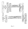
- Fig. 4 shows the working schematic diagram of a monitoring system for the damage conditions of the body.
- the smart coat formed by the information smart coat is coated at structurally dangerous or complex portions of the subject body according to the features thereof.
- a smart coat sensing network is formed by the smart coat coated on the subject body.
- at least two working electrodes are provided at selected positions of the smart coat sensing network, and both ends of the detecting circuit and the smart coat sensing network are connected.
- the working electrodes can be formed in the manner of, for example, electrode posts formed at the edge portion of the smart coat.
- the working electrodes can be formed in the manners of thin print circuit board and the like on both ends of the smart coat.
- the smart coat sensing network After the smart coat sensing network is connected to the two ends of the detecting circuit, above smart coat sensing network constitutes an equivalent resistance network.
- the detecting circuit is applied with current or voltage, so all of electrical parameters (for example, resistance, conductance, current, voltage and the like) of the detected portion under the initial damage condition (including healthy condition without damage) are stored into an external device, for example, a storage, as initial electrical data to form an original database.
- the smart coat and the body have the same surface crack producing feature, and the same or relevant crack expanding feature. Accordingly, in response to such surface crack producing feature, the same or relevant surface crack expanding feature, the equivalent resistance network formed by the smart coat sensing network is correspondingly changed.
- the electrical parameters such as the resistance, the conductance, the current, the voltage detected by the detecting circuit are also changed.
- the electrical parameters detected by the detecting circuit are inputted into the external device, such as a storage device or memory, to form the current data.
- the data is processed by a processor such as the computer, and the current data is compared with the initial data.
- the detecting circuit further comprises an alarm device.
- the alarm device When the electrical parameters detected by the detecting device exceed a predetermined limit, the alarm device output an alerting signal.
- above alerting signal can be visually displayed on a LCD display. Alternatively, above alerting signal also can be spread through sounds by a sound system.
- the detecting circuit is further provided with a cyclic detection device which allows the detecting circuit to perform cyclic detection periodically.
- the cyclic detection device also may form a smart network system with a corresponding microprocessor, so that the whole system can be operated according to a cyclic detection instruction set by a system software.
- the detecting circuit detects electrical parameters of the smart coat 5 at a predetermined cyclic detection period.
- Such cyclic detection period can be selected to have different length of time according to difference detection applications, for example, for those important equipments or facilities, such as aircraft, the cyclic detection period can be set to one period of departing and landing; for a ship, a large-scale oil tank, an oil pipeline, the cyclic detection period can be set to 10 seconds or few hours.
- the electrical parameters detected during the initial cyclic detection are stored in the storage as the initial electrical parameters.
- the detecting circuit further comprises an alarm device.
- the alarm device outputs an alerting signal. Specifically, it may give an alarm by flashing the display and/or sending sounds.
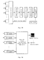
- Fig. 5 is a diagram showing a constitutional structure and an operational principle of an exemplary cyclic detection device according to the present invention, wherein Fig. 5A is a schematic diagram of a multichannel pre-submodule of the exemplary cyclic detection device according to the present invention; Fig. 5B is a schematic diagram showing a configuration of a system including an exemplary cyclic detection device according to the present invention.
- an exemplary cyclic detection device according to the present invention is primarily formed by a multichannel pre-submodule and a master control module. As shown in the figure, the whole system may be constituted by a plurality of identical pre-submodules for measurement and one master control module.
- cyclic detection device has a function of multichannel resistance measurement. Firstly, an initial resistance value for every sensor is measured and saved as a reference value. Afterward, a measured value in every time is compared with the reference value to produce a difference, the health condition of the monitored point can be known by inspecting the difference. When the difference is greater than a set threshold value, a crack occurs. When the difference is infinite, it is indicated that the sensor has been broken, and the body crack has already exceeded the monitoring range of the smart coat.
- the number of the sensor channels in which the cyclic detection device can perform the measurement may be varied from 1 to 1024 according to the actual requirement.
- the system employs distributed measuring method or wireless radiating and receiving method.
- Each of pre-submodules for measurement can measure a plurality of sensor channels (typically, 8 or 16), and be arranged to be close to each set of sensors grouped by nearby sensors.
- the pre-submodules themselves may be micro monolithic computer system, which comprises a multiple sensor signal channel option switch, a signal regulating circuit, an A/D analog -to- digital converter, a central processing unit CPU, a digital communication circuit, a power circuit, and other auxiliary circuits.
- the pre-submodules for measurement circularly measure the resistance for each senor in the form of time sharing according to the predetermined time period, and perform necessary processing for the data, and finally, send it to the master control module in the form of digital communication.
- the number of pre-submodules may be more or less depending on the number of the measured points.
- the volume of the system also can be as small as possible to facilitate the installation.
- the master control module may comprise therein: a communication unit for sending and receiving the information and data to and from each submodule; a storage unit for storing all of operation parameters and data, wherein the storage unit may be different types of storage, for example, a flash memory, a ROM, a floppy disk drive, a hard disk drive and the like. In order to reliably record the data, the storage unit can be designed with double backup systems.
- the master control module may further comprise therein: a date and clock unit for recording the date and time or working hours when the sensor resistance is changed, the time information and the sensor resistance are simultaneously recorded in the storage unit. Through the date and clock unit, the CPU can control the detecting system to detect the electrical parameters of the smart coat in a predetermined cyclic detection period, for example, a resistance value.
- the master control module may further comprise a human-computer interface.
- the data may be transferred to a computer to be processed through a computer interface, or a color LCD display with high luminance and wide operating temperature range and a thin-film push button are embedded in the master control module so that the working condition for the whole monitoring system can be displayed conveniently and visually.
- the resistance status for every channel sensor can be seen at any time, and can be displayed both in words and curves.
- the altering value of the resistance (equivalent to the altering value of the crack length) can be set so that every channel sensor can be monitored at any time. Once the altering value is reached, the display performs flash alarm and/or audible alarm is performed.
- the master control module may also comprise a central processing unit CPU for managing the operation of each unit; and a power device for supplying the power to each module.
- Fig. 6 the working process of the whole detecting system having the cyclic detection device is shown in Fig. 6 .
- the cyclic detection device is externally applied with the current or voltage, the system comes into the working state after the system initializing.
- An original data that is an initial damage condition of the structure, is collected for the first time and sent and stored into the storage device, such as a memory.
- the cyclic detection system performs cyclic detection in accordance with a cyclic detection period set by a software.
- the A/D converter converts the electrical parameters, such as resistance information, sent from the sensing layer into a digital signal suitable for the processing of a master module digital signal processing (DSP) system as the current data.
- DSP digital signal processing
- the current data is transferred to the DSP system to be analyzed and processed.
- the resistance increment or absolute resistance value for each monitored portion is displayed through a LCD display, and the variable curve of the resistance increment or that of the resistance corresponding to the resistance increment or absolute resistance value can be also visually displayed.
- the difference between the current data and the original data is reached to a predetermined range, it is determined that the subject body is damaged.
- the resistance increment of the monitored potion exceeds a predetermined alarm value, the alarm is given, for example, by the flashing of the LCD and/or sound.
Landscapes
- Physics & Mathematics (AREA)
- General Physics & Mathematics (AREA)
- Investigating Or Analyzing Materials By The Use Of Electric Means (AREA)
- Testing Of Devices, Machine Parts, Or Other Structures Thereof (AREA)
Applications Claiming Priority (2)
| Application Number | Priority Date | Filing Date | Title |
|---|---|---|---|
| CNB2006101045594A CN100535648C (zh) | 2006-09-12 | 2006-09-12 | 具有随附损伤特性的损伤探测信息智能涂层 |
| PCT/CN2007/002701 WO2008043250A1 (en) | 2006-09-12 | 2007-09-12 | Smart coating for damage detected information, inspecting device and damage inspecting method using said coating |
Publications (3)
| Publication Number | Publication Date |
|---|---|
| EP2063243A1 true EP2063243A1 (de) | 2009-05-27 |
| EP2063243A4 EP2063243A4 (de) | 2012-10-31 |
| EP2063243B1 EP2063243B1 (de) | 2013-11-20 |
Family
ID=37858602
Family Applications (1)
| Application Number | Title | Priority Date | Filing Date |
|---|---|---|---|
| EP07816318.5A Not-in-force EP2063243B1 (de) | 2006-09-12 | 2007-09-12 | Intelligente beschichtung für beschädigungsdetektierte informationen, untersuchungseinrichtung und die beschichtung verwendendes beschädigungsuntersuchungsverfahren |
Country Status (4)
| Country | Link |
|---|---|
| US (1) | US7938012B2 (de) |
| EP (1) | EP2063243B1 (de) |
| CN (1) | CN100535648C (de) |
| WO (1) | WO2008043250A1 (de) |
Cited By (1)
| Publication number | Priority date | Publication date | Assignee | Title |
|---|---|---|---|---|
| EP3211405A4 (de) * | 2014-10-21 | 2018-04-18 | Unebe Corporation | Strukturobjektüberwachungsvorrichtung und strukturobjektüberwachungsverfahren |
Families Citing this family (21)
| Publication number | Priority date | Publication date | Assignee | Title |
|---|---|---|---|---|
| CN100535648C (zh) | 2006-09-12 | 2009-09-02 | 吕志刚 | 具有随附损伤特性的损伤探测信息智能涂层 |
| US8094960B2 (en) * | 2008-07-07 | 2012-01-10 | Harris Corporation | Spectral calibration of image pairs using atmospheric characterization |
| US20100154556A1 (en) * | 2008-12-24 | 2010-06-24 | Huiming Yin | Strain Guage and Fracture Indicator Based on Composite Film Including Chain-Structured Magnetically Active Particles |
| US8886388B2 (en) * | 2009-06-29 | 2014-11-11 | The Boeing Company | Embedded damage detection system for composite materials of an aircraft |
| CN102107845B (zh) * | 2009-12-25 | 2013-11-13 | 中国科学院金属研究所 | 一种微米传感元及其制备方法和应用 |
| RU2471752C1 (ru) * | 2011-06-20 | 2013-01-10 | Федеральное государственное бюджетное образовательное учреждение высшего профессионального образования "Восточно-Сибирский государственный университет технологий и управления" | Сырьевая смесь для высокопрочного бетона с нанодисперсной добавкой |
| CN102520023B (zh) * | 2011-11-09 | 2013-10-16 | 西安交通大学 | 一种基于信息智能涂层的裂纹监测装置及其监测方法 |
| CN102909904B (zh) * | 2012-09-26 | 2015-03-04 | 中国人民解放军装甲兵工程学院 | 一种精确感知损伤智能涂层及其制备方法 |
| US9046468B2 (en) | 2012-09-26 | 2015-06-02 | Academy Of Armored Forces Engineering | Smart coating and method for manufacturing the same |
| CN103412007A (zh) * | 2013-01-10 | 2013-11-27 | 哈尔滨飞机工业集团有限责任公司 | 一种监控疲劳裂纹的方法 |
| JP6256832B2 (ja) * | 2013-12-27 | 2018-01-10 | 住友電工プリントサーキット株式会社 | 歪ゲージ用プリント配線板 |
| CN105738567A (zh) * | 2014-12-10 | 2016-07-06 | 中国飞机强度研究所 | 一种银粉涂层传感器及其加工工艺 |
| CN105334235B (zh) * | 2015-12-01 | 2019-02-01 | 兰毓华 | 一种裂纹探测系统及其探测方法 |
| CN107478170B (zh) * | 2017-08-29 | 2019-06-28 | 北京航空航天大学 | 一种光纤应变花和智能涂层集成传感器的实现方法 |
| CN107590975B (zh) * | 2017-09-08 | 2019-04-16 | 北京航空航天大学 | 基于光纤、智能涂层和压电传感器的告警系统的实现方法 |
| US11029275B2 (en) | 2018-10-19 | 2021-06-08 | Deere & Company | Device for detecting a wear level of a wear plate |
| US11549797B2 (en) | 2018-10-26 | 2023-01-10 | Deere & Company | Device for detecting wear of replaceable components |
| US10801827B1 (en) | 2019-05-03 | 2020-10-13 | At&T Intellectual Property I, L.P. | Sensor based on smart response of two-dimensional nanomaterial and associated method |
| US11011722B1 (en) * | 2020-03-12 | 2021-05-18 | Rockwell Collins, Inc. | Electroluminescent paint indicator for a fault or failure |
| WO2021188708A1 (en) * | 2020-03-17 | 2021-09-23 | Arris Enterprises Llc | Ceramic based strain detector |
| CN119780162B (zh) * | 2024-12-24 | 2026-04-28 | 浙江工业大学 | 基于智能涂层的组合结构桥梁剪力键状态监测方法及系统 |
Family Cites Families (14)
| Publication number | Priority date | Publication date | Assignee | Title |
|---|---|---|---|---|
| US4448837A (en) * | 1982-07-19 | 1984-05-15 | Oki Densen Kabushiki Kaisha | Pressure-sensitive conductive elastic sheet |
| US4935699A (en) * | 1989-05-15 | 1990-06-19 | Westinghouse Electric Corp. | Means to detect and locate pinching and chafing of conduits |
| US5298708A (en) * | 1991-02-07 | 1994-03-29 | Minnesota Mining And Manufacturing Company | Microwave-active tape having a cured polyolefin pressure-sensitive adhesive layer |
| US5997996A (en) * | 1996-03-27 | 1999-12-07 | A-Plus Corporation | Sheet-like pressure-sensitive resistance member having electrodes, method of making the same, and sheet-like pressure-sensitive resistance member |
| US6079277A (en) * | 1997-12-12 | 2000-06-27 | The Research Foundation Of State University Of New York | Methods and sensors for detecting strain and stress |
| US6276214B1 (en) * | 1997-12-26 | 2001-08-21 | Toyoaki Kimura | Strain sensor functioned with conductive particle-polymer composites |
| US6693441B2 (en) * | 2001-11-30 | 2004-02-17 | Stmicroelectronics, Inc. | Capacitive fingerprint sensor with protective coating containing a conductive suspension |
| US7032457B1 (en) * | 2002-09-27 | 2006-04-25 | Nanodynamics, Inc. | Method and apparatus for dielectric sensors and smart skin for aircraft and space vehicles |
| US6986287B1 (en) * | 2002-09-30 | 2006-01-17 | Nanodynamics Inc. | Method and apparatus for strain-stress sensors and smart skin for aircraft and space vehicles |
| CA2525530A1 (en) * | 2003-05-14 | 2004-11-25 | Tekscan, Inc. | High temperature pressure sensitive device and method thereof |
| US7260999B2 (en) * | 2004-12-23 | 2007-08-28 | 3M Innovative Properties Company | Force sensing membrane |
| US7244500B2 (en) * | 2005-02-15 | 2007-07-17 | United States Of America As Represented By The Secretary Of The Army | Smart coating system |
| WO2006125253A1 (en) * | 2005-05-25 | 2006-11-30 | Royal Melbourne Institute Of Technology | Polymeric strain sensor |
| CN100535648C (zh) * | 2006-09-12 | 2009-09-02 | 吕志刚 | 具有随附损伤特性的损伤探测信息智能涂层 |
-
2006
- 2006-09-12 CN CNB2006101045594A patent/CN100535648C/zh active Active
-
2007
- 2007-09-12 US US12/441,002 patent/US7938012B2/en not_active Expired - Fee Related
- 2007-09-12 WO PCT/CN2007/002701 patent/WO2008043250A1/zh not_active Ceased
- 2007-09-12 EP EP07816318.5A patent/EP2063243B1/de not_active Not-in-force
Cited By (2)
| Publication number | Priority date | Publication date | Assignee | Title |
|---|---|---|---|---|
| EP3211405A4 (de) * | 2014-10-21 | 2018-04-18 | Unebe Corporation | Strukturobjektüberwachungsvorrichtung und strukturobjektüberwachungsverfahren |
| US11035812B2 (en) | 2014-10-21 | 2021-06-15 | Unebe Corporation | Structural health monitoring apparatus and monitoring method |
Also Published As
| Publication number | Publication date |
|---|---|
| CN1928539A (zh) | 2007-03-14 |
| WO2008043250A1 (en) | 2008-04-17 |
| US7938012B2 (en) | 2011-05-10 |
| EP2063243B1 (de) | 2013-11-20 |
| US20100005895A1 (en) | 2010-01-14 |
| CN100535648C (zh) | 2009-09-02 |
| EP2063243A4 (de) | 2012-10-31 |
| WO2008043250A8 (fr) | 2009-03-19 |
Similar Documents
| Publication | Publication Date | Title |
|---|---|---|
| EP2063243B1 (de) | Intelligente beschichtung für beschädigungsdetektierte informationen, untersuchungseinrichtung und die beschichtung verwendendes beschädigungsuntersuchungsverfahren | |
| US7725269B2 (en) | Sensor infrastructure | |
| AU650155B2 (en) | Conformal circuit for structural health monitoring and assessment | |
| EP1546679B1 (de) | Mikrokorrosionssensoren | |
| US8510061B2 (en) | Methods, systems, and computer readable media for wireless crack detection and monitoring | |
| BR112014020230B1 (pt) | Aparelho para medir a tensão sobre um componente de fundo de poço, método de monitoramento de uma operação de perfuração e método para medir a tensão em um componente de fundo de poço | |
| JP5004955B2 (ja) | ひずみ検知装置及びひずみ検知システム | |
| US20060002815A1 (en) | Corrosion sensing microsensors | |
| US5243298A (en) | Corrosion monitor by creating a galvanic circuit between an anode wire and a test structure | |
| JP7128566B2 (ja) | 腐食センサおよび腐食検出方法 | |
| CN110487165B (zh) | 金属裂纹检测传感器及系统 | |
| EP3671154A1 (de) | Faserverbundbauteil mit integrierter sensoranordnung für den strukturzustand | |
| US20070256942A1 (en) | Measurement Of Corrosivity | |
| US20040200295A1 (en) | MEMS sensor for detecting stress corrosion cracking | |
| AU2009212091B2 (en) | Degradation sensor | |
| CN201060175Y (zh) | 具有随附损伤特性的损伤探测信息智能涂层 | |
| US20220003704A1 (en) | Smart sensing system | |
| KR100740843B1 (ko) | 구조물 모니터링 시스템 및 방법 | |
| CN113884435B (zh) | 一种基于阵列四探针电势降技术的腐蚀监测传感器、测量系统及测量分析方法 | |
| JP2019203776A (ja) | 腐食検出装置、腐食状態判定システム及び腐食検出方法 | |
| Kramer et al. | Effect of Mechanical Stress and Environmental Conditions on Degradation of Aerospace Coatings That Guard Against Atmospheric Corrosion | |
| JPH0823537B2 (ja) | 構造物に過去に掛かった負荷の検出方法及びそれに用いる負荷検出センサ |
Legal Events
| Date | Code | Title | Description |
|---|---|---|---|
| PUAI | Public reference made under article 153(3) epc to a published international application that has entered the european phase |
Free format text: ORIGINAL CODE: 0009012 |
|
| 17P | Request for examination filed |
Effective date: 20090325 |
|
| AK | Designated contracting states |
Kind code of ref document: A1 Designated state(s): AT BE BG CH CY CZ DE DK EE ES FI FR GB GR HU IE IS IT LI LT LU LV MC MT NL PL PT RO SE SI SK TR |
|
| AX | Request for extension of the european patent |
Extension state: AL BA HR MK RS |
|
| DAX | Request for extension of the european patent (deleted) | ||
| A4 | Supplementary search report drawn up and despatched |
Effective date: 20121002 |
|
| RIC1 | Information provided on ipc code assigned before grant |
Ipc: G01L 1/20 20060101ALI20120926BHEP Ipc: G01B 7/16 20060101ALI20120926BHEP Ipc: G01L 1/22 20060101AFI20120926BHEP |
|
| 17Q | First examination report despatched |
Effective date: 20121122 |
|
| GRAP | Despatch of communication of intention to grant a patent |
Free format text: ORIGINAL CODE: EPIDOSNIGR1 |
|
| INTG | Intention to grant announced |
Effective date: 20130605 |
|
| GRAS | Grant fee paid |
Free format text: ORIGINAL CODE: EPIDOSNIGR3 |
|
| GRAA | (expected) grant |
Free format text: ORIGINAL CODE: 0009210 |
|
| AK | Designated contracting states |
Kind code of ref document: B1 Designated state(s): AT BE BG CH CY CZ DE DK EE ES FI FR GB GR HU IE IS IT LI LT LU LV MC MT NL PL PT RO SE SI SK TR |
|
| REG | Reference to a national code |
Ref country code: GB Ref legal event code: FG4D |
|
| REG | Reference to a national code |
Ref country code: CH Ref legal event code: EP |
|
| REG | Reference to a national code |
Ref country code: AT Ref legal event code: REF Ref document number: 641912 Country of ref document: AT Kind code of ref document: T Effective date: 20131215 |
|
| REG | Reference to a national code |
Ref country code: IE Ref legal event code: FG4D |
|
| REG | Reference to a national code |
Ref country code: DE Ref legal event code: R096 Ref document number: 602007033933 Country of ref document: DE Effective date: 20140116 |
|
| REG | Reference to a national code |
Ref country code: NL Ref legal event code: VDEP Effective date: 20131120 |
|
| REG | Reference to a national code |
Ref country code: AT Ref legal event code: MK05 Ref document number: 641912 Country of ref document: AT Kind code of ref document: T Effective date: 20131120 |
|
| REG | Reference to a national code |
Ref country code: LT Ref legal event code: MG4D |
|
| PG25 | Lapsed in a contracting state [announced via postgrant information from national office to epo] |
Ref country code: FI Free format text: LAPSE BECAUSE OF FAILURE TO SUBMIT A TRANSLATION OF THE DESCRIPTION OR TO PAY THE FEE WITHIN THE PRESCRIBED TIME-LIMIT Effective date: 20131120 Ref country code: NL Free format text: LAPSE BECAUSE OF FAILURE TO SUBMIT A TRANSLATION OF THE DESCRIPTION OR TO PAY THE FEE WITHIN THE PRESCRIBED TIME-LIMIT Effective date: 20131120 Ref country code: LT Free format text: LAPSE BECAUSE OF FAILURE TO SUBMIT A TRANSLATION OF THE DESCRIPTION OR TO PAY THE FEE WITHIN THE PRESCRIBED TIME-LIMIT Effective date: 20131120 Ref country code: SE Free format text: LAPSE BECAUSE OF FAILURE TO SUBMIT A TRANSLATION OF THE DESCRIPTION OR TO PAY THE FEE WITHIN THE PRESCRIBED TIME-LIMIT Effective date: 20131120 Ref country code: IS Free format text: LAPSE BECAUSE OF FAILURE TO SUBMIT A TRANSLATION OF THE DESCRIPTION OR TO PAY THE FEE WITHIN THE PRESCRIBED TIME-LIMIT Effective date: 20140320 |
|
| PG25 | Lapsed in a contracting state [announced via postgrant information from national office to epo] |
Ref country code: AT Free format text: LAPSE BECAUSE OF FAILURE TO SUBMIT A TRANSLATION OF THE DESCRIPTION OR TO PAY THE FEE WITHIN THE PRESCRIBED TIME-LIMIT Effective date: 20131120 Ref country code: BE Free format text: LAPSE BECAUSE OF FAILURE TO SUBMIT A TRANSLATION OF THE DESCRIPTION OR TO PAY THE FEE WITHIN THE PRESCRIBED TIME-LIMIT Effective date: 20131120 Ref country code: LV Free format text: LAPSE BECAUSE OF FAILURE TO SUBMIT A TRANSLATION OF THE DESCRIPTION OR TO PAY THE FEE WITHIN THE PRESCRIBED TIME-LIMIT Effective date: 20131120 Ref country code: ES Free format text: LAPSE BECAUSE OF FAILURE TO SUBMIT A TRANSLATION OF THE DESCRIPTION OR TO PAY THE FEE WITHIN THE PRESCRIBED TIME-LIMIT Effective date: 20131120 |
|
| PG25 | Lapsed in a contracting state [announced via postgrant information from national office to epo] |
Ref country code: PT Free format text: LAPSE BECAUSE OF FAILURE TO SUBMIT A TRANSLATION OF THE DESCRIPTION OR TO PAY THE FEE WITHIN THE PRESCRIBED TIME-LIMIT Effective date: 20140320 |
|
| PG25 | Lapsed in a contracting state [announced via postgrant information from national office to epo] |
Ref country code: EE Free format text: LAPSE BECAUSE OF FAILURE TO SUBMIT A TRANSLATION OF THE DESCRIPTION OR TO PAY THE FEE WITHIN THE PRESCRIBED TIME-LIMIT Effective date: 20131120 |
|
| REG | Reference to a national code |
Ref country code: DE Ref legal event code: R097 Ref document number: 602007033933 Country of ref document: DE |
|
| PG25 | Lapsed in a contracting state [announced via postgrant information from national office to epo] |
Ref country code: PL Free format text: LAPSE BECAUSE OF FAILURE TO SUBMIT A TRANSLATION OF THE DESCRIPTION OR TO PAY THE FEE WITHIN THE PRESCRIBED TIME-LIMIT Effective date: 20131120 Ref country code: CZ Free format text: LAPSE BECAUSE OF FAILURE TO SUBMIT A TRANSLATION OF THE DESCRIPTION OR TO PAY THE FEE WITHIN THE PRESCRIBED TIME-LIMIT Effective date: 20131120 Ref country code: SK Free format text: LAPSE BECAUSE OF FAILURE TO SUBMIT A TRANSLATION OF THE DESCRIPTION OR TO PAY THE FEE WITHIN THE PRESCRIBED TIME-LIMIT Effective date: 20131120 Ref country code: RO Free format text: LAPSE BECAUSE OF FAILURE TO SUBMIT A TRANSLATION OF THE DESCRIPTION OR TO PAY THE FEE WITHIN THE PRESCRIBED TIME-LIMIT Effective date: 20131120 |
|
| PLBE | No opposition filed within time limit |
Free format text: ORIGINAL CODE: 0009261 |
|
| STAA | Information on the status of an ep patent application or granted ep patent |
Free format text: STATUS: NO OPPOSITION FILED WITHIN TIME LIMIT |
|
| PG25 | Lapsed in a contracting state [announced via postgrant information from national office to epo] |
Ref country code: DK Free format text: LAPSE BECAUSE OF FAILURE TO SUBMIT A TRANSLATION OF THE DESCRIPTION OR TO PAY THE FEE WITHIN THE PRESCRIBED TIME-LIMIT Effective date: 20131120 |
|
| 26N | No opposition filed |
Effective date: 20140821 |
|
| REG | Reference to a national code |
Ref country code: DE Ref legal event code: R097 Ref document number: 602007033933 Country of ref document: DE Effective date: 20140821 |
|
| PG25 | Lapsed in a contracting state [announced via postgrant information from national office to epo] |
Ref country code: SI Free format text: LAPSE BECAUSE OF FAILURE TO SUBMIT A TRANSLATION OF THE DESCRIPTION OR TO PAY THE FEE WITHIN THE PRESCRIBED TIME-LIMIT Effective date: 20131120 |
|
| PG25 | Lapsed in a contracting state [announced via postgrant information from national office to epo] |
Ref country code: LU Free format text: LAPSE BECAUSE OF FAILURE TO SUBMIT A TRANSLATION OF THE DESCRIPTION OR TO PAY THE FEE WITHIN THE PRESCRIBED TIME-LIMIT Effective date: 20140912 Ref country code: MC Free format text: LAPSE BECAUSE OF FAILURE TO SUBMIT A TRANSLATION OF THE DESCRIPTION OR TO PAY THE FEE WITHIN THE PRESCRIBED TIME-LIMIT Effective date: 20131120 |
|
| REG | Reference to a national code |
Ref country code: CH Ref legal event code: PL |
|
| REG | Reference to a national code |
Ref country code: IE Ref legal event code: MM4A |
|
| PG25 | Lapsed in a contracting state [announced via postgrant information from national office to epo] |
Ref country code: LI Free format text: LAPSE BECAUSE OF NON-PAYMENT OF DUE FEES Effective date: 20140930 Ref country code: CH Free format text: LAPSE BECAUSE OF NON-PAYMENT OF DUE FEES Effective date: 20140930 |
|
| PG25 | Lapsed in a contracting state [announced via postgrant information from national office to epo] |
Ref country code: IE Free format text: LAPSE BECAUSE OF NON-PAYMENT OF DUE FEES Effective date: 20140912 Ref country code: IT Free format text: LAPSE BECAUSE OF FAILURE TO SUBMIT A TRANSLATION OF THE DESCRIPTION OR TO PAY THE FEE WITHIN THE PRESCRIBED TIME-LIMIT Effective date: 20131120 |
|
| PG25 | Lapsed in a contracting state [announced via postgrant information from national office to epo] |
Ref country code: BG Free format text: LAPSE BECAUSE OF FAILURE TO SUBMIT A TRANSLATION OF THE DESCRIPTION OR TO PAY THE FEE WITHIN THE PRESCRIBED TIME-LIMIT Effective date: 20131120 |
|
| PG25 | Lapsed in a contracting state [announced via postgrant information from national office to epo] |
Ref country code: MT Free format text: LAPSE BECAUSE OF FAILURE TO SUBMIT A TRANSLATION OF THE DESCRIPTION OR TO PAY THE FEE WITHIN THE PRESCRIBED TIME-LIMIT Effective date: 20131120 Ref country code: GR Free format text: LAPSE BECAUSE OF FAILURE TO SUBMIT A TRANSLATION OF THE DESCRIPTION OR TO PAY THE FEE WITHIN THE PRESCRIBED TIME-LIMIT Effective date: 20140221 Ref country code: CY Free format text: LAPSE BECAUSE OF FAILURE TO SUBMIT A TRANSLATION OF THE DESCRIPTION OR TO PAY THE FEE WITHIN THE PRESCRIBED TIME-LIMIT Effective date: 20131120 |
|
| PG25 | Lapsed in a contracting state [announced via postgrant information from national office to epo] |
Ref country code: TR Free format text: LAPSE BECAUSE OF FAILURE TO SUBMIT A TRANSLATION OF THE DESCRIPTION OR TO PAY THE FEE WITHIN THE PRESCRIBED TIME-LIMIT Effective date: 20131120 Ref country code: HU Free format text: LAPSE BECAUSE OF FAILURE TO SUBMIT A TRANSLATION OF THE DESCRIPTION OR TO PAY THE FEE WITHIN THE PRESCRIBED TIME-LIMIT; INVALID AB INITIO Effective date: 20070912 |
|
| REG | Reference to a national code |
Ref country code: FR Ref legal event code: PLFP Year of fee payment: 10 |
|
| REG | Reference to a national code |
Ref country code: FR Ref legal event code: PLFP Year of fee payment: 11 |
|
| REG | Reference to a national code |
Ref country code: FR Ref legal event code: PLFP Year of fee payment: 12 |
|
| REG | Reference to a national code |
Ref country code: GB Ref legal event code: 732E Free format text: REGISTERED BETWEEN 20180719 AND 20180725 |
|
| REG | Reference to a national code |
Ref country code: DE Ref legal event code: R082 Ref document number: 602007033933 Country of ref document: DE Representative=s name: BOEHMERT & BOEHMERT ANWALTSPARTNERSCHAFT MBB -, DE Ref country code: DE Ref legal event code: R081 Ref document number: 602007033933 Country of ref document: DE Owner name: JINYI ANDA AVIATION TECHNOLOGY (BEIJING) CO., , CN Free format text: FORMER OWNER: SHAOXING JINGGONG EQUIPMENT MONITORING TECHNOLOGY CO., LTD., SHAOXING, CN |
|
| PGFP | Annual fee paid to national office [announced via postgrant information from national office to epo] |
Ref country code: GB Payment date: 20220923 Year of fee payment: 16 Ref country code: DE Payment date: 20220916 Year of fee payment: 16 |
|
| PGFP | Annual fee paid to national office [announced via postgrant information from national office to epo] |
Ref country code: FR Payment date: 20220921 Year of fee payment: 16 |
|
| REG | Reference to a national code |
Ref country code: DE Ref legal event code: R082 Ref document number: 602007033933 Country of ref document: DE Representative=s name: SKM-IP SCHMID KRAUSS KUTTENKEULER MALESCHA SCH, DE |
|
| REG | Reference to a national code |
Ref country code: DE Ref legal event code: R119 Ref document number: 602007033933 Country of ref document: DE |
|
| GBPC | Gb: european patent ceased through non-payment of renewal fee |
Effective date: 20230912 |
|
| PG25 | Lapsed in a contracting state [announced via postgrant information from national office to epo] |
Ref country code: GB Free format text: LAPSE BECAUSE OF NON-PAYMENT OF DUE FEES Effective date: 20230912 |
|
| PG25 | Lapsed in a contracting state [announced via postgrant information from national office to epo] |
Ref country code: GB Free format text: LAPSE BECAUSE OF NON-PAYMENT OF DUE FEES Effective date: 20230912 Ref country code: FR Free format text: LAPSE BECAUSE OF NON-PAYMENT OF DUE FEES Effective date: 20230930 Ref country code: DE Free format text: LAPSE BECAUSE OF NON-PAYMENT OF DUE FEES Effective date: 20240403 |