EP2063041B1 - Élément mural prefabriqué avec une ossature pour fixer des plaques - Google Patents
Élément mural prefabriqué avec une ossature pour fixer des plaques Download PDFInfo
- Publication number
- EP2063041B1 EP2063041B1 EP08157652A EP08157652A EP2063041B1 EP 2063041 B1 EP2063041 B1 EP 2063041B1 EP 08157652 A EP08157652 A EP 08157652A EP 08157652 A EP08157652 A EP 08157652A EP 2063041 B1 EP2063041 B1 EP 2063041B1
- Authority
- EP
- European Patent Office
- Prior art keywords
- insulation layer
- concrete
- wall element
- skeleton
- channels
- Prior art date
- Legal status (The legal status is an assumption and is not a legal conclusion. Google has not performed a legal analysis and makes no representation as to the accuracy of the status listed.)
- Not-in-force
Links
Images


Classifications
-
- E—FIXED CONSTRUCTIONS
- E04—BUILDING
- E04C—STRUCTURAL ELEMENTS; BUILDING MATERIALS
- E04C2/00—Building elements of relatively thin form for the construction of parts of buildings, e.g. sheet materials, slabs, or panels
- E04C2/02—Building elements of relatively thin form for the construction of parts of buildings, e.g. sheet materials, slabs, or panels characterised by specified materials
- E04C2/26—Building elements of relatively thin form for the construction of parts of buildings, e.g. sheet materials, slabs, or panels characterised by specified materials composed of materials covered by two or more of groups E04C2/04, E04C2/08, E04C2/10 or of materials covered by one of these groups with a material not specified in one of the groups
- E04C2/284—Building elements of relatively thin form for the construction of parts of buildings, e.g. sheet materials, slabs, or panels characterised by specified materials composed of materials covered by two or more of groups E04C2/04, E04C2/08, E04C2/10 or of materials covered by one of these groups with a material not specified in one of the groups at least one of the materials being insulating
- E04C2/288—Building elements of relatively thin form for the construction of parts of buildings, e.g. sheet materials, slabs, or panels characterised by specified materials composed of materials covered by two or more of groups E04C2/04, E04C2/08, E04C2/10 or of materials covered by one of these groups with a material not specified in one of the groups at least one of the materials being insulating composed of insulating material and concrete, stone or stone-like material
-
- E—FIXED CONSTRUCTIONS
- E04—BUILDING
- E04C—STRUCTURAL ELEMENTS; BUILDING MATERIALS
- E04C2/00—Building elements of relatively thin form for the construction of parts of buildings, e.g. sheet materials, slabs, or panels
- E04C2/30—Building elements of relatively thin form for the construction of parts of buildings, e.g. sheet materials, slabs, or panels characterised by the shape or structure
- E04C2/38—Building elements of relatively thin form for the construction of parts of buildings, e.g. sheet materials, slabs, or panels characterised by the shape or structure with attached ribs, flanges, or the like, e.g. framed panels
- E04C2/384—Building elements of relatively thin form for the construction of parts of buildings, e.g. sheet materials, slabs, or panels characterised by the shape or structure with attached ribs, flanges, or the like, e.g. framed panels with a metal frame
Definitions
- the present invention relates to a prefabricated wall element comprising: a first insulation layer, a second insulation layer arranged on the first insulation layer and forming channels for allowing the molding of a load bearing concrete structure.
- a third insulation layer is arranged such that is covers the second insulation layer and the load bearing concrete structure and a concrete layer covers the third insulation layer.
- the invention also relates to a method of manufacturing a wall element.
- prefabricated wall elements made of reinforced concrete For house building, it is well known to use prefabricated wall elements made of reinforced concrete.
- a prefabricated wall element made of reinforced concrete and insulation layers is disclosed in DE 20200501746U1 .
- such wall elements include an outer, load bearing shell and an inner shell, both made of reinforced concrete.
- An insulating layer is usually provided between the inner shell and the outer shell.
- Wall elements of the known type have many advantages; they are easy and fast to mount, give an even indoor temperature due to the thermal inertia of the heavy inner shell and a good sound insulation.
- prefabricated concrete wall elements provide excellent resistance to fire and decomposition caused by water entrainment.
- the manufacturing method for prior art element comprises basically the following steps:
- concrete is poured onto the insulation.
- the concrete is allowed to harden overnight, and the following morning (or later) the wall element is removed from the mould table to leave room for manufacturing of another wall element.
- a wooden wall such a wall generally comprises a structure made from wooden beams, and the inside is covered with plaster board; it is light and it is relatively easy to retrofit the wall with internal wiring and piping.
- wooden walls There are, however, some severe drawbacks with wooden walls, primarily that they are not very resistant to fire, and that they may rot if subjected to water or moist.
- the object of the present invention is to provide a wall element that is lighter than the prior art prefabricated wall elements, have the same (or better) resistance against fire, that allow easy retrofitting of internal wiring, and that does not rot.
- the invention solves, or at least mitigates, some or all of the above problems by providing a prefabricated wall element comprising a skeleton including beams having a first side adapted for fastening of boards and a second side facing the first insulation layer.
- a first insulation layer may be made from mineral wool.
- the second and third insulation layers may be made from expanded or extruded polystyrene.
- the beams of the skeleton may be made from profiles of sheet metal.
- the skeleton In order to increase the strength of the skeleton, it may be fastened to the load bearing concrete structure by elongate fastening means.
- the elongate fastening means may be a screw extending through the first insulation layer, from the skeleton to the load bearing concrete structure. By using a screw, it is possible to arrange the screw after the second insulation layer has been arranged.
- the skeleton may be arranged such that it faces an indoor space of a building.
- the wall may be arranged such that the concrete layer faces an indoor space of a building.
- the invention also relates to a method of manufacturing a wall element.
- the method includes the steps of:
- reinforcement bars may be arranged in the channels, and on the third insulation layer prior to pouring the concrete in the channels and on the third insulation layer, respectively.
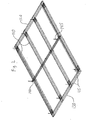
- a fastening skeleton 100 is shown.
- the skeleton 100 may be manufactured from any suitable material enabling fastening by screws, e.g. a sheet metal profile, although it may also be possible to use plastic or wood for the skeleton 100.
- the skeleton 100 comprises standing beams 110 placed in parallel relationship to one another.
- the distance between the beams 110 may e.g. be 450mm or 600 mm.
- the beams are fastened to upper and lower beams 120 and 130, respectively.
- the upper 120 and lower 130 beams extend perpendicularly to the beams 110.
- a typical profile usable for the beams 110, 120,130 is shown.
- the profile can, as mentioned, be manufactured from sheet metal, and comprises a front portion 111, side portions 112 and a back portion 113.
- the back portion 113 is provided with an opening; this opening has, however, no effect, but is the result of manufacturing the profile from sheet metal.
- the skeleton 100 may comprise a crossbeam 140.
- the crossbeam 140 is a Z-profile made from sheet metal.
- the Z-profile comprises three different portions, namely an upper portion 141, an intermediate portion 142 and a lower portion 143.
- the lower portion 143 is fastened to the back portion 113 of the beams 110.
- the intermediate portion has a height (i.e. the distance between the upper and lower portions 141 and 143, respectively) that corresponds to a thickness of an insulation layer that is placed onto the skeleton 100.
- the crossbeam 140 might be provided with means 145 for fastening the crossbeam to further sections of the wall element; examples of such means can be found in Fig. 2 and comprise a perforated steel ribbon fastened in the crossbeam 140.
- the upper and lower beams 120 and 130 are fastened to the beams 110 in a suitable manner.
- One such manner could be the use of nail plates 115, which e.g. is screwed flush with the back portion 113.
- the nail plates 115 are screwed the back portion 113 of the beams 113, the upper beam 120 and the lower beam 130.
- a reinforcement part 150 may be inserted into the profile comprised in the beams 110, 120 and 130.
- the reinforcement part 150 could comprise two screw portions 151, two support legs 152 and an intermediate surface 153 situated between the two screw portions 151.
- the intermediate surface 153 has a lower level as compared to the screw portions 151. This has an effect that will be described later.
- the reinforcement part 150 is as mentioned inserted into the profile it is supposed to reinforce; it is inserted such that the screw portions 151 will abut the back portion 113 of the beams 110, 120 and 130. In this position, the support legs 152 will extend from the corners defined by the front portion 111 and the side portions 112 to the screw portions 151, and hence serve to hold the screw portions 151 firmly against the back portion 113.
- FIG. 2 A three-dimensional view of a skeleton 100 (provided with a crossbeam) is shown in Fig. 2 . Moreover, in the embodiment shown in Fig. 2 , the reinforcement parts 150 are shown, being placed in the ends of each beam 110.
- the invention relates to a wall element, and in order to obtain the wall element, the following measures are taken, reference being made to Figs. 3 , 4 and 5 :
- the concrete layer 500 is connected to the concrete poured into the channels formed in the insulation layer 300.
- This connection can be achieved e.g. by means of plates (not shown) provided with openings for insertion of reinforcement bars.
- This technique for connecting concrete layers divided by an insulation layer is well known by persons skilled in the art, and will hence not be described further.
- the wall element can be removed from the horizontal surface and be transported to a building site. It should be noted that the horizontal surface on which the wall element is manufactured will be clean after the wall element has been removed; hence, a large amount of work can be saved.
- the wall element according to any of the above embodiments can be used in at least two ways;
- the wall element is used such that the skeleton 100 will face in a direction corresponding to an interior volume of the building.
- the skeleton is preferably covered with e.g. a plaster board to form an interior wall surface pleasing to the eye.
- the skeleton 100 is preferably made from a material allowing screwing, and if the material used for the skeleton allows for screwing, the plaster boards can be fastened by screws. It is, however, also possible to use e.g. glue to fasten the plasterboards to the skeleton 100.
- the first use embodiment has the advantage that it is possible to fit the wall with e.g. electric wiring prior to the provision of the plaster boards on the skeleton.
- the wall element is used such that the skeleton 100 will face "outwards", i.e. towards the surface intended to become the outer wall.
- the skeleton is preferably clad with a board resistant to the influence of weather and wind.
- the second use embodiment has two advantages over prior art walls; firstly, it is possible to renew a worn façade, and moreover, the indoor temperature will be more even.
- a frame surrounds the skeleton.
- This embodiment will be described below, with reference to Figs. 6 to 10 .
- Most features are common for the earlier described embodiments and the embodiment that will be described below, and the methods for manufacturing the wall element are identical, but for the sake of clarity, the description will be complete also for the following embodiments.
- details not described in the above embodiments may be used for those embodiments, and details described for the above embodiments, but not for the following embodiments may be used for them.
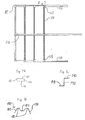
- a plan view of a concrete grid 10 comprised in one embodiment of a prefabricated wall element according to the present invention is shown.
- the concrete grid 10 comprises a ground beam 11, a main bar 12 and columns 13 connecting the ground beam 11 and the main bar 12. If the grid 10 is to be used in a wall element for a room in a lower plane, the columns might extend slightly above the upper level of the main bar 12, in order to enable fastening of a double flooring for an upper plane in the lateral plane.
- the ground beam 11, the main bar 12 and the columns 13 are reinforced, preferably by steel reinforcement bars in a way well known by persons skilled in the art, by steel fibers, or by glass fiber reinforcements, either in form of short fibers, or in form of elongate bars.
- the distance between the columns may be chosen depending on such factors as the weight of upper storey's supported by the wall element, strength of the columns (which, in turn, depends on the amount of reinforcement used in the column, and its width) and strength of the main bar; should a beam of the double flooring for an optional upper plane rest on the main bar between two columns and the distance between two adjacent columns be large, it is crucial that the main bar is sufficiently strong.
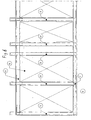
- a frame/form 20a used for manufacturing and constituting an outer limit of the finished wall element of the present invention is shown.
- the frame/form 20a comprises two horizontal frame members 21, 22 and a number of vertical frame portions 19.
- Such vertical frame portions could e.g. be used for delimiting vertical walls of a window opening, such as shown in the blow-up B1 of Fig. 6 .
- further frame portions 19a and 19b, which delimit horizontal walls of the window opening join the vertical frame portions 19 delimiting the vertical walls of the window opening.
- the frame/form 20a might be manufactured from U-shaped sheet metal profiles, wherein the opening of the U preferably faces inwards with regards to the frame portions 19, 21 and 22, i.e. opening of the U will face the concrete used to manufacture the wall.
- Fig. 8 the same frame/form 20a is shown, but in Fig.8 , the frame/form 20a is provided with vertically extending sheet metal profiles 17, which join the two horizontal frame members 21, 22 and serve as suspension beams for gypsum or plaster boards used as inner walls of the wall element of the present invention.
- the sheet metal profiles may e.g. be of the type sold by Lindab under the trade name S7-25, which are adapted for allowing screwing of the gypsum or plasterboards to the sheet metal profiles. It is also possible to glue the plasterboards to the sheet metal profiles, but which method that is used is up to the persons mounting the wall element in the building to be built by the wall elements.
- the sheet metal profiles 17 may be fastened to the horizontal frame members 21, 22 and the frame portions 19a and 19b in any suitable way, e.g. by screwing, gluing, riveting, welding or by spot welding.
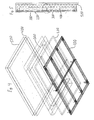
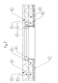
- Fig. 9 shows a finished wall element according to the present invention.
- a plasterboard attached to the sheet metal profiles 17.
- an insulation layer 20 e.g. an expanded plastic board or a board of mineral wool.
- the insulation layer 15 and the insulation layer delimits at least two sides of the vertical concrete columns 13.
- an insulation layer 30 is provided, and on the outside of the insulation 30, there is provided a concrete layer 31.
- the insulation layer 30 is perforated by plates (not shown) of stainless steel extending from the columns 13 to the concrete layer 30.
- the purpose of the stainless steel plates is to fix the mutual position of the columns and the concrete layer 30.
- the steel plates are perforated, and reinforcement bars are placed in the perforations and allowed to fasten in the poured concrete.
- the frame/form 20a is assembled, e.g. by welding, gluing, riveting, welding or point welding.
- the frame portions 21, 19, 19a, 19b from rusting, it might be suitable if these portions are painted or covered by a thin zinc plating.
- the sheet metal profiles 17 are fastened to the frame portions 21.
- the sheet metal profiles 17 are laid down flat on a horizontal surface such that the frame portions 21 will face "upwards". In some cases, it might be useful if it is possible to "tilt" the horizontal surface in order to facilitate removing of a finished wall element. In conjunction to this step, it might be suitable to build a form for allowing pouring of concrete on a higher level than allowed by the frame/form 20a.
- the insulation layer 20 is laid onto the sheet metal profiles 17.
- the insulation layer 20 preferably should be rigid enough to support the weight of concrete to be poured onto the insulation layer 20.
- the insulation 15 is attached to the insulation, such that there will be “channels” delimited by side walls of the insulation 15 or the frame 21 and by top surfaces of the insulation 20. These channels will be filled with concrete in a subsequent manufacturing step and hence form the main bar 12, the columns 13 and the ground beam 11.
- reinforcement bars in the required thicknesses and numbers are laid in the channels forming the main bar 12, the columns 13 and the ground beam 11.
- the reinforcement bars are laid in such channels in a way well known by persons skilled in the art.
- the stainless steel plates are placed in the channels at this stage, wherein the reinforcement bars preferably will be inserted through the perforations in the steel plates.
- concrete will be poured in the channels. If considered necessary, the concrete will be vibrated, a process well known by persons skilled in the art of concrete building.
- the insulation layer 30 will be laid on top of the insulation layer 15 and the poured concrete forming the main bar 12, the columns 13 and the ground beam 11.
- the stainless steel plates will extend through this insulation layer, either through holes arranged in the insulation, or through junctions between the boards constituting the insulation layer 30.
- an optional reinforcement is added on top of the insulation layer 30, whereupon concrete to form the concrete layer 31 will be poured onto the insulation layer 300.
- the concrete will be left to harden for a certain amount of time, e.g. over night, after which hardening it will be possible to remove the finished wall element from the horizontal surface it has occupied.
Landscapes
- Engineering & Computer Science (AREA)
- Architecture (AREA)
- Civil Engineering (AREA)
- Structural Engineering (AREA)
- Building Environments (AREA)
- Panels For Use In Building Construction (AREA)
Claims (9)
- Elément de mur préfabriqué comprenant :une première couche d'isolation (200, 20)une deuxième couche d'isolation (300 ; 15) agencée sur la première couche d'isolation (200 ; 20) et formant des canaux pour permettre le moulage d'une structure de béton porteuse de charge (13) ;une troisième couche d'isolation (400 ; 30) agencée de telle sorte qu'elle couvre la deuxième couche d'isolation (300 ; 15) et la structure de béton porteuse de charge (13) etune couche de béton (500 ; 31) couvrant la troisième couche d'isolation (400 ; 30), caractérisé parune ossature (100 ; 17) incluant des poutres (110, 120, 130) comportant un premier côté adapté pour la fixation de panneaux et un second côté en regard de la première couche d'isolation (200 ; 20).
- Elément de mur selon la revendication 1, dans lequel la première couche d'isolation (200 ; 20) est constituée de laine minérale et où les deuxième (300 ; 15) et troisième (400 ; 30) couches d'isolation sont constituées de poly(styrène) expansé ou extrudé.
- Elément de mur selon la revendication 1 ou 2, dans lequel les poutres (110, 120, 130) de l'ossature (100) sont constituées de profilés de tôle métallique.
- Elément de mur selon l'une quelconque des revendications précédentes, dans lequel le squelette (100) est fixé à la structure de béton porteuse de charge par un moyen de fixation allongé (310).
- Elément de mur selon la revendication 4, dans lequel le moyen de fixation allongé (310) est une vis s'étendant à travers la première couche d'isolation (200), de l'ossature (100) à la structure de béton porteuse de charge.
- Utilisation d'un élément de mur selon l'une quelconque des revendications précédentes, caractérisée en ce que l'ossature (100 ; 17) est agencée de telle sorte qu'elle est en regard d'un espace intérieur d'un bâtiment.
- Utilisation d'un élément de mur selon l'une quelconque des revendications 1 à 5, caractérisée en ce que la couche de béton (500) est agencée de telle sorte qu'elle est en regard d'un espace intérieur d'un bâtiment.
- Procédé de fabrication d'un élément de mur, caractérisé par les étapes consistant à :i. agencer une ossature (100) comprenant des poutres (110, 120, 130) dans un moule ;ii. couvrir lesdites poutres (110, 120, 130) avec une première couche d'isolation (200) ;iii. sur ladite première couche d'isolation, appliquer une deuxième couche d'isolation (300) définissant des canaux adaptés pour mouler une structure porteuse de charge ;iv. agencer un moyen de fixation s'étendant depuis les canaux, à travers la première couche d'isolation, vers les poutres (110, 120, 130) ;v. verser du béton dans les canaux ;vi. couvrir ledit béton et ladite deuxième couche d'isolation (300) avec une troisième couche d'isolation (400) etvii. couvrir la troisième couche d'isolation (400) avec une couche de béton.
- Procédé selon la revendication 8, comprenant en outre l'étape consistant à :viii. agencer des barres d'armature dans les canaux, et sur la troisième couche d'isolation (400) préalablement au versement du béton dans les canaux et sur la troisième couche d'isolation, respectivement.
Applications Claiming Priority (1)
| Application Number | Priority Date | Filing Date | Title |
|---|---|---|---|
| SE0702589 | 2007-11-23 |
Publications (2)
| Publication Number | Publication Date |
|---|---|
| EP2063041A1 EP2063041A1 (fr) | 2009-05-27 |
| EP2063041B1 true EP2063041B1 (fr) | 2009-12-16 |
Family
ID=40280771
Family Applications (1)
| Application Number | Title | Priority Date | Filing Date |
|---|---|---|---|
| EP08157652A Not-in-force EP2063041B1 (fr) | 2007-11-23 | 2008-06-05 | Élément mural prefabriqué avec une ossature pour fixer des plaques |
Country Status (3)
| Country | Link |
|---|---|
| EP (1) | EP2063041B1 (fr) |
| AT (1) | ATE452254T1 (fr) |
| DE (1) | DE602008000414D1 (fr) |
Families Citing this family (2)
| Publication number | Priority date | Publication date | Assignee | Title |
|---|---|---|---|---|
| RU2485260C1 (ru) * | 2012-03-28 | 2013-06-20 | Закрытое акционерное общество "Полиметалл-М" | Многослойная строительная панель |
| CN108343193A (zh) * | 2018-04-28 | 2018-07-31 | 山东省建设发展研究院 | 一种轻型预制装配式外墙板及其制备方法 |
Family Cites Families (5)
| Publication number | Priority date | Publication date | Assignee | Title |
|---|---|---|---|---|
| DE2636572A1 (de) * | 1976-08-13 | 1978-02-16 | Werner Eufinger | Wandelement zur errichtung von gebaeuden |
| CH674751A5 (en) * | 1988-01-06 | 1990-07-13 | Markus Senn | Wall component for tall building erection - has heat insulation outside porous concrete plate, and external heat insulation cover |
| CN100353015C (zh) * | 2003-01-28 | 2007-12-05 | 郑志伟 | 复合夹芯墙板 |
| DE202005017046U1 (de) * | 2005-11-02 | 2006-03-02 | Glatthaar-Fertigkeller Gmbh | Bewehrter Dämmkörper für eine wärmegedämmte Fertigteilwand und Fertigteilwand |
| EP1959069B1 (fr) * | 2007-02-13 | 2009-05-06 | Iconorm GmbH | Corps d'isolation sans joint pour une paroi d'extrémité calorifugée et paroi d'extrémité tout comme son procédé de fabrication |
-
2008
- 2008-06-05 DE DE602008000414T patent/DE602008000414D1/de not_active Expired - Fee Related
- 2008-06-05 AT AT08157652T patent/ATE452254T1/de not_active IP Right Cessation
- 2008-06-05 EP EP08157652A patent/EP2063041B1/fr not_active Not-in-force
Also Published As
| Publication number | Publication date |
|---|---|
| DE602008000414D1 (de) | 2010-01-28 |
| EP2063041A1 (fr) | 2009-05-27 |
| ATE452254T1 (de) | 2010-01-15 |
Similar Documents
| Publication | Publication Date | Title |
|---|---|---|
| EP3133220B1 (fr) | Plateforme pour balcon et son procédé de production | |
| US4669240A (en) | Precast reinforced concrete wall panels and method of erecting same | |
| US9010050B2 (en) | Pre-cast rain screen wall panel | |
| CA2674833C (fr) | Panneau mural en beton prefabrique avec ecran pare-pluie | |
| US7946092B2 (en) | Method of constructing a building, such building, and wall and floor elements for use therein | |
| HUT68939A (en) | Sheet metal structural member, construction panel and method of construction | |
| CA2788118C (fr) | Constrution de surfaces en beton a charpente metallique legere et son procede de construction | |
| US20060254208A1 (en) | Paneling system and method | |
| JPWO2006129801A1 (ja) | 内外装材下地兼用型枠パネル及びコンクリート構造物の型枠工法 | |
| US20100088975A1 (en) | Method of producing a heavy modular unit and a modular unit produced according to the method | |
| RU79304U1 (ru) | Стеновое ограждение для зданий и сооружений (варианты) | |
| EP2063041B1 (fr) | Élément mural prefabriqué avec une ossature pour fixer des plaques | |
| WO2010144951A1 (fr) | Panneau mural thermique, système de construction et procédés d'utilisation et de construction associés | |
| JP3010344B2 (ja) | プレキャストコンクリートパネル | |
| FI98398C (fi) | Seinäelementti | |
| KR100693244B1 (ko) | 천장의 슬라브 시공에 이용되는 거푸집 대체용마감단열보드 및 이를 이용한 천장의 슬라브 구조 및 그시공 방법 | |
| KR100622018B1 (ko) | 건축물의 구축방법 및 이로부터 구축된 건축물 | |
| KR101440556B1 (ko) | 모듈러 건축물의 바닥판 구조체 | |
| WO2007040412A2 (fr) | Plancher en beton suspendu | |
| EP4310266A1 (fr) | Panneau de construction stratifié et son procédé de fabrication | |
| EP2449185B1 (fr) | Système d'isolation supplémentaire et procédé pour isoler une façade | |
| RU2422603C1 (ru) | Блок несъемной опалубки перекрытия | |
| US20200123761A1 (en) | High-rise self-supporting formwork building system | |
| WO1997046774A1 (fr) | Structure de paroi ou analogue | |
| EP3524743B1 (fr) | Salle de bain préfabriquée |
Legal Events
| Date | Code | Title | Description |
|---|---|---|---|
| PUAI | Public reference made under article 153(3) epc to a published international application that has entered the european phase |
Free format text: ORIGINAL CODE: 0009012 |
|
| AK | Designated contracting states |
Kind code of ref document: A1 Designated state(s): AT BE BG CH CY CZ DE DK EE ES FI FR GB GR HR HU IE IS IT LI LT LU LV MC MT NL NO PL PT RO SE SI SK TR |
|
| AX | Request for extension of the european patent |
Extension state: AL BA MK RS |
|
| REG | Reference to a national code |
Ref country code: SE Ref legal event code: TRCL |
|
| 17P | Request for examination filed |
Effective date: 20090611 |
|
| GRAP | Despatch of communication of intention to grant a patent |
Free format text: ORIGINAL CODE: EPIDOSNIGR1 |
|
| RTI1 | Title (correction) |
Free format text: PREFABRICATED WALL ELEMENT WITH A SKELETON FOR FASTENING BOARDS |
|
| GRAS | Grant fee paid |
Free format text: ORIGINAL CODE: EPIDOSNIGR3 |
|
| GRAA | (expected) grant |
Free format text: ORIGINAL CODE: 0009210 |
|
| AK | Designated contracting states |
Kind code of ref document: B1 Designated state(s): AT BE BG CH CY CZ DE DK EE ES FI FR GB GR HR HU IE IS IT LI LT LU LV MC MT NL NO PL PT RO SE SI SK TR |
|
| REG | Reference to a national code |
Ref country code: GB Ref legal event code: FG4D |
|
| REG | Reference to a national code |
Ref country code: CH Ref legal event code: EP |
|
| REG | Reference to a national code |
Ref country code: IE Ref legal event code: FG4D |
|
| REF | Corresponds to: |
Ref document number: 602008000414 Country of ref document: DE Date of ref document: 20100128 Kind code of ref document: P |
|
| AKX | Designation fees paid |
Designated state(s): AT BE BG CH CY CZ DE DK EE ES FI FR GB GR HR HU IE IS IT LI LT LU LV MC MT NL NO PL PT RO SE SI SK TR |
|
| REG | Reference to a national code |
Ref country code: SE Ref legal event code: TRGR |
|
| REG | Reference to a national code |
Ref country code: NL Ref legal event code: VDEP Effective date: 20091216 |
|
| PG25 | Lapsed in a contracting state [announced via postgrant information from national office to epo] |
Ref country code: NO Free format text: LAPSE BECAUSE OF FAILURE TO SUBMIT A TRANSLATION OF THE DESCRIPTION OR TO PAY THE FEE WITHIN THE PRESCRIBED TIME-LIMIT Effective date: 20100316 Ref country code: LT Free format text: LAPSE BECAUSE OF FAILURE TO SUBMIT A TRANSLATION OF THE DESCRIPTION OR TO PAY THE FEE WITHIN THE PRESCRIBED TIME-LIMIT Effective date: 20091216 Ref country code: FI Free format text: LAPSE BECAUSE OF FAILURE TO SUBMIT A TRANSLATION OF THE DESCRIPTION OR TO PAY THE FEE WITHIN THE PRESCRIBED TIME-LIMIT Effective date: 20091216 |
|
| LTIE | Lt: invalidation of european patent or patent extension |
Effective date: 20091216 |
|
| PG25 | Lapsed in a contracting state [announced via postgrant information from national office to epo] |
Ref country code: PL Free format text: LAPSE BECAUSE OF FAILURE TO SUBMIT A TRANSLATION OF THE DESCRIPTION OR TO PAY THE FEE WITHIN THE PRESCRIBED TIME-LIMIT Effective date: 20091216 Ref country code: SI Free format text: LAPSE BECAUSE OF FAILURE TO SUBMIT A TRANSLATION OF THE DESCRIPTION OR TO PAY THE FEE WITHIN THE PRESCRIBED TIME-LIMIT Effective date: 20091216 Ref country code: LV Free format text: LAPSE BECAUSE OF FAILURE TO SUBMIT A TRANSLATION OF THE DESCRIPTION OR TO PAY THE FEE WITHIN THE PRESCRIBED TIME-LIMIT Effective date: 20091216 Ref country code: HR Free format text: LAPSE BECAUSE OF FAILURE TO SUBMIT A TRANSLATION OF THE DESCRIPTION OR TO PAY THE FEE WITHIN THE PRESCRIBED TIME-LIMIT Effective date: 20091216 |
|
| PG25 | Lapsed in a contracting state [announced via postgrant information from national office to epo] |
Ref country code: AT Free format text: LAPSE BECAUSE OF FAILURE TO SUBMIT A TRANSLATION OF THE DESCRIPTION OR TO PAY THE FEE WITHIN THE PRESCRIBED TIME-LIMIT Effective date: 20091216 |
|
| PG25 | Lapsed in a contracting state [announced via postgrant information from national office to epo] |
Ref country code: EE Free format text: LAPSE BECAUSE OF FAILURE TO SUBMIT A TRANSLATION OF THE DESCRIPTION OR TO PAY THE FEE WITHIN THE PRESCRIBED TIME-LIMIT Effective date: 20091216 Ref country code: NL Free format text: LAPSE BECAUSE OF FAILURE TO SUBMIT A TRANSLATION OF THE DESCRIPTION OR TO PAY THE FEE WITHIN THE PRESCRIBED TIME-LIMIT Effective date: 20091216 Ref country code: ES Free format text: LAPSE BECAUSE OF FAILURE TO SUBMIT A TRANSLATION OF THE DESCRIPTION OR TO PAY THE FEE WITHIN THE PRESCRIBED TIME-LIMIT Effective date: 20100327 Ref country code: IS Free format text: LAPSE BECAUSE OF FAILURE TO SUBMIT A TRANSLATION OF THE DESCRIPTION OR TO PAY THE FEE WITHIN THE PRESCRIBED TIME-LIMIT Effective date: 20100416 Ref country code: RO Free format text: LAPSE BECAUSE OF FAILURE TO SUBMIT A TRANSLATION OF THE DESCRIPTION OR TO PAY THE FEE WITHIN THE PRESCRIBED TIME-LIMIT Effective date: 20091216 Ref country code: BG Free format text: LAPSE BECAUSE OF FAILURE TO SUBMIT A TRANSLATION OF THE DESCRIPTION OR TO PAY THE FEE WITHIN THE PRESCRIBED TIME-LIMIT Effective date: 20100316 |
|
| PG25 | Lapsed in a contracting state [announced via postgrant information from national office to epo] |
Ref country code: BE Free format text: LAPSE BECAUSE OF FAILURE TO SUBMIT A TRANSLATION OF THE DESCRIPTION OR TO PAY THE FEE WITHIN THE PRESCRIBED TIME-LIMIT Effective date: 20091216 Ref country code: SK Free format text: LAPSE BECAUSE OF FAILURE TO SUBMIT A TRANSLATION OF THE DESCRIPTION OR TO PAY THE FEE WITHIN THE PRESCRIBED TIME-LIMIT Effective date: 20091216 Ref country code: CZ Free format text: LAPSE BECAUSE OF FAILURE TO SUBMIT A TRANSLATION OF THE DESCRIPTION OR TO PAY THE FEE WITHIN THE PRESCRIBED TIME-LIMIT Effective date: 20091216 |
|
| PLBE | No opposition filed within time limit |
Free format text: ORIGINAL CODE: 0009261 |
|
| STAA | Information on the status of an ep patent application or granted ep patent |
Free format text: STATUS: NO OPPOSITION FILED WITHIN TIME LIMIT |
|
| PG25 | Lapsed in a contracting state [announced via postgrant information from national office to epo] |
Ref country code: GR Free format text: LAPSE BECAUSE OF FAILURE TO SUBMIT A TRANSLATION OF THE DESCRIPTION OR TO PAY THE FEE WITHIN THE PRESCRIBED TIME-LIMIT Effective date: 20100317 Ref country code: CY Free format text: LAPSE BECAUSE OF FAILURE TO SUBMIT A TRANSLATION OF THE DESCRIPTION OR TO PAY THE FEE WITHIN THE PRESCRIBED TIME-LIMIT Effective date: 20091216 |
|
| 26N | No opposition filed |
Effective date: 20100917 |
|
| PG25 | Lapsed in a contracting state [announced via postgrant information from national office to epo] |
Ref country code: DK Free format text: LAPSE BECAUSE OF FAILURE TO SUBMIT A TRANSLATION OF THE DESCRIPTION OR TO PAY THE FEE WITHIN THE PRESCRIBED TIME-LIMIT Effective date: 20091216 Ref country code: MC Free format text: LAPSE BECAUSE OF NON-PAYMENT OF DUE FEES Effective date: 20100630 |
|
| REG | Reference to a national code |
Ref country code: FR Ref legal event code: ST Effective date: 20110228 |
|
| PG25 | Lapsed in a contracting state [announced via postgrant information from national office to epo] |
Ref country code: IT Free format text: LAPSE BECAUSE OF FAILURE TO SUBMIT A TRANSLATION OF THE DESCRIPTION OR TO PAY THE FEE WITHIN THE PRESCRIBED TIME-LIMIT Effective date: 20091216 |
|
| PG25 | Lapsed in a contracting state [announced via postgrant information from national office to epo] |
Ref country code: MT Free format text: LAPSE BECAUSE OF FAILURE TO SUBMIT A TRANSLATION OF THE DESCRIPTION OR TO PAY THE FEE WITHIN THE PRESCRIBED TIME-LIMIT Effective date: 20091216 Ref country code: IE Free format text: LAPSE BECAUSE OF NON-PAYMENT OF DUE FEES Effective date: 20100605 Ref country code: DE Free format text: LAPSE BECAUSE OF NON-PAYMENT OF DUE FEES Effective date: 20110101 |
|
| PG25 | Lapsed in a contracting state [announced via postgrant information from national office to epo] |
Ref country code: FR Free format text: LAPSE BECAUSE OF NON-PAYMENT OF DUE FEES Effective date: 20100630 |
|
| PG25 | Lapsed in a contracting state [announced via postgrant information from national office to epo] |
Ref country code: LU Free format text: LAPSE BECAUSE OF NON-PAYMENT OF DUE FEES Effective date: 20100605 Ref country code: PT Free format text: LAPSE BECAUSE OF FAILURE TO SUBMIT A TRANSLATION OF THE DESCRIPTION OR TO PAY THE FEE WITHIN THE PRESCRIBED TIME-LIMIT Effective date: 20100516 Ref country code: HU Free format text: LAPSE BECAUSE OF FAILURE TO SUBMIT A TRANSLATION OF THE DESCRIPTION OR TO PAY THE FEE WITHIN THE PRESCRIBED TIME-LIMIT Effective date: 20100617 |
|
| PG25 | Lapsed in a contracting state [announced via postgrant information from national office to epo] |
Ref country code: TR Free format text: LAPSE BECAUSE OF FAILURE TO SUBMIT A TRANSLATION OF THE DESCRIPTION OR TO PAY THE FEE WITHIN THE PRESCRIBED TIME-LIMIT Effective date: 20091216 |
|
| REG | Reference to a national code |
Ref country code: CH Ref legal event code: PL |
|
| REG | Reference to a national code |
Ref country code: CH Ref legal event code: PL |
|
| GBPC | Gb: european patent ceased through non-payment of renewal fee |
Effective date: 20120605 |
|
| PG25 | Lapsed in a contracting state [announced via postgrant information from national office to epo] |
Ref country code: GB Free format text: LAPSE BECAUSE OF NON-PAYMENT OF DUE FEES Effective date: 20120605 Ref country code: CH Free format text: LAPSE BECAUSE OF NON-PAYMENT OF DUE FEES Effective date: 20120630 Ref country code: LI Free format text: LAPSE BECAUSE OF NON-PAYMENT OF DUE FEES Effective date: 20120630 |
|
| PGFP | Annual fee paid to national office [announced via postgrant information from national office to epo] |
Ref country code: SE Payment date: 20210608 Year of fee payment: 14 |
|
| REG | Reference to a national code |
Ref country code: SE Ref legal event code: EUG |
|
| PG25 | Lapsed in a contracting state [announced via postgrant information from national office to epo] |
Ref country code: SE Free format text: LAPSE BECAUSE OF NON-PAYMENT OF DUE FEES Effective date: 20220606 |