EP2062772A1 - Device for adjusting height of automobile seat - Google Patents
Device for adjusting height of automobile seat Download PDFInfo
- Publication number
- EP2062772A1 EP2062772A1 EP07744093A EP07744093A EP2062772A1 EP 2062772 A1 EP2062772 A1 EP 2062772A1 EP 07744093 A EP07744093 A EP 07744093A EP 07744093 A EP07744093 A EP 07744093A EP 2062772 A1 EP2062772 A1 EP 2062772A1
- Authority
- EP
- European Patent Office
- Prior art keywords
- side frame
- frame section
- linkage arm
- linkage
- rearward
- Prior art date
- Legal status (The legal status is an assumption and is not a legal conclusion. Google has not performed a legal analysis and makes no representation as to the accuracy of the status listed.)
- Granted
Links
Images

Classifications
-
- B—PERFORMING OPERATIONS; TRANSPORTING
- B60—VEHICLES IN GENERAL
- B60N—SEATS SPECIALLY ADAPTED FOR VEHICLES; VEHICLE PASSENGER ACCOMMODATION NOT OTHERWISE PROVIDED FOR
- B60N2/00—Seats specially adapted for vehicles; Arrangement or mounting of seats in vehicles
- B60N2/02—Seats specially adapted for vehicles; Arrangement or mounting of seats in vehicles the seat or part thereof being movable, e.g. adjustable
- B60N2/04—Seats specially adapted for vehicles; Arrangement or mounting of seats in vehicles the seat or part thereof being movable, e.g. adjustable the whole seat being movable
- B60N2/16—Seats specially adapted for vehicles; Arrangement or mounting of seats in vehicles the seat or part thereof being movable, e.g. adjustable the whole seat being movable height-adjustable
- B60N2/1635—Seats specially adapted for vehicles; Arrangement or mounting of seats in vehicles the seat or part thereof being movable, e.g. adjustable the whole seat being movable height-adjustable characterised by the drive mechanism
- B60N2/165—Gear wheel driven mechanism
-
- B—PERFORMING OPERATIONS; TRANSPORTING
- B60—VEHICLES IN GENERAL
- B60N—SEATS SPECIALLY ADAPTED FOR VEHICLES; VEHICLE PASSENGER ACCOMMODATION NOT OTHERWISE PROVIDED FOR
- B60N2/00—Seats specially adapted for vehicles; Arrangement or mounting of seats in vehicles
- B60N2/02—Seats specially adapted for vehicles; Arrangement or mounting of seats in vehicles the seat or part thereof being movable, e.g. adjustable
- B60N2/04—Seats specially adapted for vehicles; Arrangement or mounting of seats in vehicles the seat or part thereof being movable, e.g. adjustable the whole seat being movable
- B60N2/16—Seats specially adapted for vehicles; Arrangement or mounting of seats in vehicles the seat or part thereof being movable, e.g. adjustable the whole seat being movable height-adjustable
- B60N2/1605—Seats specially adapted for vehicles; Arrangement or mounting of seats in vehicles the seat or part thereof being movable, e.g. adjustable the whole seat being movable height-adjustable characterised by the cinematic
- B60N2/161—Rods
- B60N2/1615—Parallelogram-like structure
-
- B—PERFORMING OPERATIONS; TRANSPORTING
- B60—VEHICLES IN GENERAL
- B60N—SEATS SPECIALLY ADAPTED FOR VEHICLES; VEHICLE PASSENGER ACCOMMODATION NOT OTHERWISE PROVIDED FOR
- B60N2/00—Seats specially adapted for vehicles; Arrangement or mounting of seats in vehicles
- B60N2/02—Seats specially adapted for vehicles; Arrangement or mounting of seats in vehicles the seat or part thereof being movable, e.g. adjustable
- B60N2/04—Seats specially adapted for vehicles; Arrangement or mounting of seats in vehicles the seat or part thereof being movable, e.g. adjustable the whole seat being movable
- B60N2/16—Seats specially adapted for vehicles; Arrangement or mounting of seats in vehicles the seat or part thereof being movable, e.g. adjustable the whole seat being movable height-adjustable
- B60N2/168—Seats specially adapted for vehicles; Arrangement or mounting of seats in vehicles the seat or part thereof being movable, e.g. adjustable the whole seat being movable height-adjustable and provided with braking systems
Definitions
- the present invention relates to a height adjusting device for an automobile seat, which allows a height of the seat to be adjusted according to an occupant's physique.
- an automobile seat which includes a height adjusting device provided between first and second pairs of spaced apart base brackets, mounted on a pair of first and second spaced apart upper rail members of a slide rail mechanism, and a pair of first and second spaced apart side frame sections of a frame for a seat cushion of the seat.
- the height adjusting device includes two pairs of forward and rearward linkage arms, the forward linkage arms being bridged between the side frame sections and the first pair of spaced apart brackets, the rearward linkage arms being bridged between the side frame sections and the second pair of spaced apart brackets, a linkage rod connected, via a first support pin, at a rearward end portion thereof to one of the rearward linkage arms which is arranged on the side of the first side frame section, a first connection shaft interconnecting the forward linkage arms, a second connection shaft interconnecting the rearward linkage arms, and an actuating mechanism which includes an operation knob arranged outside the first side frame section of the seat cushion frame and having a rotating shaft rotatably penetrated through the first side frame section, a pinion gear arranged inside the first side frame section and mounted around an end portion of the rotating shaft of the operating knob which is projected inward from the first side frame section, and a sector gear arranged inside the first side frame section and meshed with the pinion gear (Japanese Patent Application Laid-
- the sector gear is supported at a base portion thereof to the first side frame section by a second support pin, and the linkage rod is connected at a forward end portion thereof to the sector gear by a third support pin.
- the operation knob is rotated in a counterclockwise direction or a clockwise direction
- the pinion gear and the sector gear are rotated to thereby draw the linkage rod in such a manner to cause the linkage rod to be moved forward or rearward according to the rotation direction of the operation knob.
- the forward and rearward linkage arms are pivoted so as to rise up or pivoted so as to be collapsed according to the rotational direction of the operation knob.
- the components of the actuating mechanism are supported or connected by many support pins and the number of the components is thus increased, so that much time is required for assembling of the actuating mechanism, thus resulting in increase of the assembling cost.
- a spiral spring may be also employed. From the viewpoint of operation-load, it is preferable that the spiral spring is provided so as to facilitate rotation of the sector gear.
- the spiral spring may be stretched between the second support pin for causing the sector gear to be supported to the first side frame section, and the third support pin for causing the linkage rod to be connected to the sector gear.
- an innermost end of the spiral spring may be retained around an end portion of the second support pin which is projected inward from the sector gear, but an outermost end portion of the spiral spring is required to be retained around an axial portion of the third support pin, interconnecting the linkage rod and the sector gear, which is located between the linkage rod and the sector gear.
- Such an arrangement of the spiral spring not only requires a lot of work to assemble a peripheral structure around the sections to which the spiral spring is retained, but also prevents easy replacement of the spiral spring.
- the second support pin supporting the sector gear is required to have a large diameter from the viewpoint of rigidity.
- a height adjusting device for an automobile seat.
- the automobile seat includes a seat cushion frame having a pair of first and second spaced apart side frame sections, and first and second pairs of spaced apart base brackets.
- the height adjusting device comprises a pair of first and second forward linkage arms, the first forward linkage arm being bridged between the first side frame section and corresponding one of the first pair of spaced apart brackets and supported at a substantially middle portion thereof to the first side frame section by a fixing pin, the second forward linkage arm being bridged between the second side frame section and the other of the first pair of spaced apart brackets and supported at a substantially middle portion thereof to the second side frame section, a pair of first and second rearward linkage arms, the first rearward linkage arm being bridged between the first side frame section and corresponding one of the second pair of spaced apart brackets and supported at a substantially middle portion thereof to the first side frame section, the second rearward linkage arm being bridged between the second side frame section and the other of the second pair of spaced apart space
- the actuating mechanism includes an operation knob having a rotating shaft, the operation knob being arranged outside the first side frame section with the rotating shaft being rotatably penetrated through the first side frame section, a pinion gear mounted around the rotating shaft, a sector gear for directly drawing the first linkage rod, the sector gear being arranged inside the first side frame section and meshed with the pinion gear, and a spiral spring for directly biasing the first forward linkage arm in a rising-up direction, the sector gear being arranged between the first side frame section and the first forward linkage arm and supported at a base portion thereof to the fixing pin of the first forward linkage arm, the sector gear having a planting pin provided at a corner portion thereof adjacent gear teeth thereof so as to be projected from the sector gear, the first forward linkage arm and the first linkage rod being connected to each other by the fixing pin, and the spiral spring being stretched between the fixing pin and the planting pin with an innermost end portion thereof being retained around an end of the fixing pin which is projected inward from the first forward linkage arm, and with an outermost end portion thereof
- the fixing pin which supports the first forward linkage arm is also used as a support pin for supporting the sector gear and the planting pin projecting from the sector gear is used as a connection pin for interconnecting the first forward linkage arm and the first linkage rod, so that a special support pin for supporting the sector gear is not required, and the first forward linkage arm and the first linkage rod are connected to each other by the single support pin. Therefore, the number of components of the height adjusting device is reduced, and reduction in time required to assemble the height adjusting device and reduction in the assembling cost thereof can be realized.
- the spiral spring is stretched between the fixing pin and the planting pin with the innermost end portion thereof being retained around the end of the fixing pin which is projected inward from the first forward linkage arm, and with the outermost end portion thereof being retained around the end of the planting pin which is projected inward from a connection portion between the first forward linkage arm and the first linkage rod.
- the fixing pin is provided at the end thereof with a spring-retaining member
- the spiral spring has a large spring constant
- the innermost end portion of the spiral spring is retained to the spring-retaining member.
- the height adjusting device is to be provided at an assistant seat which is employed in an automobile having a steering wheel on the right side of an automobile body.
- the automobile seat includes a frame for a seat cushion, the frame including a pair of spaced apart side frame sections, and a slide rail mechanism for allowing an entire seat to be moved in a forward/rearward direction in the automobile body, the slide rail mechanism including a pair of spaced apart lower rail members and a pair of spaced apart upper rail members slidably supported to said lower rail members so as to be slidable along the lower rail members.
- the height adjusting device includes an operation knob for operating an actuating mechanism of the height adjusting device.
- the operation knob is arranged outside one of the spaced apart side frame sections.
- only one of the spaced apart side frame sections, only one of the spaced apart lower rail members, and only one of the spaced apart upper rail members are shown. More particularly, a side frame section, a lower rail member, and an upper rail member which are arranged on the side at which the operation knob is not arranged are mainly omitted from the illustration, and a side frame section, a lower rail member, and an upper rail member which are arranged on the side at which the operation knob is arranged are mainly shown in the drawings.
- the operation knob is arranged outside a side of a forward portion of a left side frame section of the seat cushion frame.
- the height adjusting device is provided at the slide-type seat in which an entire seat comprising the seat cushion and a seat back can be moved in the forward/rearward direction along the spaced apart lower rail members R of the slide rail mechanism S which are installed on an automobile body floor.
- Each of the spaced apart upper rail members A is provided with spaced apart base brackets B 1 , B 2 which are spaced apart from each other in a longitudinal direction of the upper rail member A and rise up from the upper rail member A.
- the height adjusting device includes two pairs of forward and rearward linkage arms 2, 3, each of the forward linkage arms 2 being arranged between corresponding one of the side frame sections 1 and the forward base bracket B 1 of corresponding one of the upper rail members A, each of the rearward linkage arms 3 being arranged between corresponding one of the side frame sections 1 and the rearward base bracket B 2 of corresponding one of the upper rail members A, a linkage rod 4 connected between each of the forward linkage arms 2 and each of the rearward linkage arms 3, a first connection shaft 5 interconnecting the forward linkage arms 2, a second connection shaft 6 interconnecting the rearward linkage arms 3, and the actuating mechanism.
- Each of the forward linkage arms 2 is supported at a substantially middle portion thereof to the corresponding side frame section 1 by a fixing pin 2a.
- each of the rearward linkage arms 3 is supported at a substantially middle portion thereof to the corresponding side frame section 1 by a fixing pin 3a.
- each of the forward linkage arms 2 is pivotally supported at a lower end portion thereof to a corresponding base bracket B 1 by a support pin 2b and each of the rearward linkage arms 3 is pivotally supported at a lower end portion thereof to a corresponding base bracket B 2 by a support pin 3b.
- the linkage rod 4 arranged on the side at which the operation knob is not arranged is connected at a forward end portion thereof to an upper end portion of a corresponding forward linkage arm 2 by a support pin 4a and connected a rearward end portion thereof to an upper end portion of a corresponding rearward linkage arm 3 by a support pin 4b.
- the linkage rod 4 arranged on the side at which the operation knob is arranged is connected at a forward end portion thereof to an upper end portion of a corresponding forward linkage arm 2 by a planting pin 16 (see Fig. 2 ) which will be discussed hereinafter, and connected at a rearward end portion thereof to an upper end portion of a corresponding rearward linkage arm 3 by a support pin 4b.
- the actuating mechanism includes the operation knob 10 arranged outside the left side frame section 1 with a rotating shaft 11 thereof being rotatably penetrated the left side frame section 1, a pinion gear 12 mounted around the rotating shaft 11, a sector gear 13 meshed with the pinion gear 12, and a spiral spring 14 for directly pulling a linkage rod 4 which is arranged on the side at which the operating knob is arranged.
- a different spiral spring may be applied to the forward linkage arm and/or the rearward linkage arm which is arranged on the side at which the operation knob is not arranged.
- the left side frame section 1 at which the operation knob 10 is arranged includes a housing portion 1a which is formed by causing a portion of the left side frame section 1 to be embossed inward from a surface of the left side frame section 1 and has a substantially dome-shape in outline.
- the rotating shaft 11 of the operation knob 10 is rotatably penetrated through a top of the substantially dome-shaped housing portion 1 a with the pinion gear 12 mounted around the rotating shaft 11 being received in the housing portion 1a.
- a brake section 15 is applied and fixed onto an outer surface of the left side frame section 1 so as to surround the rotating shaft 11.
- the substantially dome-shaped housing portion 1a is formed with a notch (not shown) through which the pinion gear 12 and the sector gear 13 arranged inside the left side frame section 1 are meshed with each other.
- the sector gear 13 is arranged between the left side frame section 1 and the corresponding forward linkage arm 2 with a base portion 13a thereof being supported by the fixing pin 2a of the forward linkage arm 2.
- the planting pin 16 which has been briefly discussed above is protrusively provided on a corner portion of the sector gear 13 which is adjacent gear teeth 13b of the sector gear 13 and offset from the fixing pin 2a.
- the forward linkage arm 2 and the linkage rod 4 which are shown in Fig. 2 and arranged adjacent the first side frame section are connected to each other by the planting pin 16.
- the fixing pin 2a of the forward linkage arm 2 is fixed to the left side frame section 1 by riveting.
- the planting pin 16 is fixed to the sector gear 13 by riveting.
- a reference numeral 1b denotes a through-hole which is formed in the left side frame section 1 and through which the fixing pin 2a is inserted
- a reference numeral 2c denotes a through-hole which is formed in the forward linkage arm 2 and through which the support pin 2b for interconnecting the lower end portion of the forward linkage arm 2 and the base bracket B 1 is inserted
- a reference numeral 2d designates a fixing hole which is formed in the forward linkage arm 2 and in which an end of the first connection shaft 5 interconnecting the forward linkage arms 2 is inserted
- a reference numeral 2e denotes a through-hole which is formed in the forward linkage arm 2 and through which the planting pin 16 of the sector gear 13 is inserted
- a reference numeral 4c designates a through-hole which is formed in the linkage rod 4 and through which the planting pin 16 is inserted
- a reference numeral 13c denotes a through-hole which is formed in the base portion of the sector gear 13 and through which the
- the spiral spring 14 is retained at an innermost end portion 14a thereof around the fixing pin 2a which is penetrated through the substantially middle portion of the forward linkage arm 2, and retained at an outermost end portion 14b thereof around the planting pin 16 which is penetrated through a connection portion between the forward linkage arm 2 and the linkage rod 4, so that the forward linkage arm 2 is biased in a rising-up direction by the spiral spring 14.
- the innermost end portion 14a of the spiral spring 14 may be retained to a spring-retaining member 18 which is protruded from an end of the fixing pin 2a.
- the outermost end portion 14b of the spiral spring 14 is retained to a small diameter axial-portion (see Fig. 2 ) of the planting pin 16.
- the spring-retaining member 18 includes a substantially cup-shaped base portion 18a, a narrow-width extension portion 18b of a substantially arc-shape in cross-section rising up from a region of a peripheral edge of the substantially cup-shaped base portion 18a, and a stopper portion 18c of a substantially arc-shaped in cross-section provided at an end of the narrow-width extension portion 18b and extending laterally with respect to the narrow-width extension portion 18b.
- the end of the fixing pin 2a is fitted through a through-hole formed in the substantially cup-shaped base portion 18a and secured to the base portion 18a by riveting.
- the innermost end portion 14a of the spiral spring 14 is retained around the narrow-width extension portion 18b and engaged with the laterally extending stopper portion 18c so as not to be unwound from the narrow-width extension portion 18b.
- the pinion gear 12 is rotated in the same direction.
- the sector gear 13 which is meshed with the pinion gear 12 is rotated in a clockwise direction.
- the planting pin 16 of the sector gear 13 which is arranged at a location which is offset from the fixing pin 2a is moved so as to cause the forward linkage arm 2 to be pivoted upward.
- the linkage rod 4 which is connected to the forward linkage arm 2 is forward drawn and the rearward linkage arm 2 is also pivoted upward.
- the fixing pin 2a of the forward linkage arm 2 which is shown in Fig. 2 is also used as a support pin for the sector gear 13, and the planting pin 16 of the sector gear 13 is used for a connection pin which interconnects the forward linkage arm 2 and the linkage rod 4, so that reduction of the number of parts of the height adjusting device, reduction of time to be required for assembling of the height adjusting device, and reduction of the assembling cost of the height adjusting device can be realized.
- the spiral spring 14 is retained at the innermost end portion 14a thereof to the spring-retaining member 18 attached to the end of the fixing pin 2a which is projected from the substantially middle portion of the forward linkage arm 2, and retained at the outermost end portion 14b thereof to the planting pin 16 which is penetrated through the connection portion between the forward linkage arm 2 and the linkage rod 4, so that after-attaching of the spiral spring 14 can be carried out.
- a peripheral structure around the sections to which the spiral spring 14 is applied can be simplified, and replacement of the spiral spring can be easily carried out.
- the innermost end portion 14a of the spiral spring 14 is retained around the narrow-width extension portion 18b of the spring-retaining member 18 and the outermost end portion 14b of the spiral spring 14 is retained around the planting pin 16, so that even if there is a limitation on an offset amount between the fixing pin 2a and the planting pin 16, the spiral spring of a large spring constant can be employed. Therefore, by causing the operation knob to be rotated with small power, the seat can be vertically moved, thus making it possible to improve operability of the height adjusting device.
- the actuating mechanism may be arranged at a rearward portion of the side frame section.
Landscapes
- Engineering & Computer Science (AREA)
- Aviation & Aerospace Engineering (AREA)
- Transportation (AREA)
- Mechanical Engineering (AREA)
- Seats For Vehicles (AREA)
Abstract
Description
- The present invention relates to a height adjusting device for an automobile seat, which allows a height of the seat to be adjusted according to an occupant's physique.
- As an automobile seat, there is proposed an automobile seat which includes a height adjusting device provided between first and second pairs of spaced apart base brackets, mounted on a pair of first and second spaced apart upper rail members of a slide rail mechanism, and a pair of first and second spaced apart side frame sections of a frame for a seat cushion of the seat.
- The height adjusting device includes two pairs of forward and rearward linkage arms, the forward linkage arms being bridged between the side frame sections and the first pair of spaced apart brackets, the rearward linkage arms being bridged between the side frame sections and the second pair of spaced apart brackets, a linkage rod connected, via a first support pin, at a rearward end portion thereof to one of the rearward linkage arms which is arranged on the side of the first side frame section, a first connection shaft interconnecting the forward linkage arms, a second connection shaft interconnecting the rearward linkage arms, and an actuating mechanism which includes an operation knob arranged outside the first side frame section of the seat cushion frame and having a rotating shaft rotatably penetrated through the first side frame section, a pinion gear arranged inside the first side frame section and mounted around an end portion of the rotating shaft of the operating knob which is projected inward from the first side frame section, and a sector gear arranged inside the first side frame section and meshed with the pinion gear (Japanese Patent Application Laid-Open No.
2001-138780 WO2004/094180A1 ). - In the height adjusting device, the sector gear is supported at a base portion thereof to the first side frame section by a second support pin, and the linkage rod is connected at a forward end portion thereof to the sector gear by a third support pin. When the operation knob is rotated in a counterclockwise direction or a clockwise direction, the pinion gear and the sector gear are rotated to thereby draw the linkage rod in such a manner to cause the linkage rod to be moved forward or rearward according to the rotation direction of the operation knob. Synchronously with such movement of the linkage rod, the forward and rearward linkage arms are pivoted so as to rise up or pivoted so as to be collapsed according to the rotational direction of the operation knob.
- In the actuating mechanism of the height adjusting device, the components of the actuating mechanism are supported or connected by many support pins and the number of the components is thus increased, so that much time is required for assembling of the actuating mechanism, thus resulting in increase of the assembling cost.
- As a height adjusting device for an automobile seat, there is known a height adjusting device which is configured so as to lift the automobile seat up with resort to rotational torque exerted by a spiral spring (Japanese Patent Application Laid-Open Nos.
2000-108734 2000-127813 - In the actuating mechanism including the pinion gear and the sector gear which have been discussed above, a spiral spring may be also employed. From the viewpoint of operation-load, it is preferable that the spiral spring is provided so as to facilitate rotation of the sector gear. In the installation structure of the sector gear which has been discussed above, the spiral spring may be stretched between the second support pin for causing the sector gear to be supported to the first side frame section, and the third support pin for causing the linkage rod to be connected to the sector gear.
- If the spiral spring is stretched between the second and third support pins as discussed above, an innermost end of the spiral spring may be retained around an end portion of the second support pin which is projected inward from the sector gear, but an outermost end portion of the spiral spring is required to be retained around an axial portion of the third support pin, interconnecting the linkage rod and the sector gear, which is located between the linkage rod and the sector gear. Such an arrangement of the spiral spring not only requires a lot of work to assemble a peripheral structure around the sections to which the spiral spring is retained, but also prevents easy replacement of the spiral spring.
- The second support pin supporting the sector gear is required to have a large diameter from the viewpoint of rigidity. In addition, there is a limitation on an offset amount between the second support pin of the sector gear and the third support pin of the linkage rod, so that it is impossible to obtain an installation space for a spiral spring of a large spring constant.
- It is an object of the present invention to provide a height adjusting device for an automobile seat, which facilitates simplification of a peripheral structure around spring-installing sections for a spiral spring of the height adjusting device, facilitates reduction of time required to assemble the height adjusting device, makes it possible to reduce the assembling cost of the height adjusting device, and makes it possible to easily perform replacement of the spiral spring.
- It is another object of the present invention to provide a height adjusting device for an automobile seat, which is provided with a spiral spring of a large spring constant and benefits excellent operability of the height adjusting device.
- In accordance with the present invention, there is provided a height adjusting device for an automobile seat. The automobile seat includes a seat cushion frame having a pair of first and second spaced apart side frame sections, and first and second pairs of spaced apart base brackets. The height adjusting device comprises a pair of first and second forward linkage arms, the first forward linkage arm being bridged between the first side frame section and corresponding one of the first pair of spaced apart brackets and supported at a substantially middle portion thereof to the first side frame section by a fixing pin, the second forward linkage arm being bridged between the second side frame section and the other of the first pair of spaced apart brackets and supported at a substantially middle portion thereof to the second side frame section, a pair of first and second rearward linkage arms, the first rearward linkage arm being bridged between the first side frame section and corresponding one of the second pair of spaced apart brackets and supported at a substantially middle portion thereof to the first side frame section, the second rearward linkage arm being bridged between the second side frame section and the other of the second pair of spaced apart brackets and supported at a substantially middle portion thereof to the second side frame section, a first linkage rod connected at a forward end and a rearward end thereof to an upper end of the first forward linkage arm and an upper end of the first rearward linkage arm, a second linkage rod connected at a forward end and a rearward end thereof to an upper end of the second forward linkage arm and an upper end of the second rearward linkage arm, a first connection shaft interconnecting the forward linkage arms, a second connection shaft interconnecting the rearward linkage arms, and an actuating mechanism for causing the forward and rearward linkage arms to be vertically pivoted. The actuating mechanism includes an operation knob having a rotating shaft, the operation knob being arranged outside the first side frame section with the rotating shaft being rotatably penetrated through the first side frame section, a pinion gear mounted around the rotating shaft, a sector gear for directly drawing the first linkage rod, the sector gear being arranged inside the first side frame section and meshed with the pinion gear, and a spiral spring for directly biasing the first forward linkage arm in a rising-up direction, the sector gear being arranged between the first side frame section and the first forward linkage arm and supported at a base portion thereof to the fixing pin of the first forward linkage arm, the sector gear having a planting pin provided at a corner portion thereof adjacent gear teeth thereof so as to be projected from the sector gear, the first forward linkage arm and the first linkage rod being connected to each other by the fixing pin, and the spiral spring being stretched between the fixing pin and the planting pin with an innermost end portion thereof being retained around an end of the fixing pin which is projected inward from the first forward linkage arm, and with an outermost end portion thereof being retained around an end of the planting pin which is projected inward from a connection portion between the first forward linkage arm and the first linkage rod.
- In the height adjusting device for the automobile seat, which is constructed as discussed above, the fixing pin which supports the first forward linkage arm is also used as a support pin for supporting the sector gear and the planting pin projecting from the sector gear is used as a connection pin for interconnecting the first forward linkage arm and the first linkage rod, so that a special support pin for supporting the sector gear is not required, and the first forward linkage arm and the first linkage rod are connected to each other by the single support pin. Therefore, the number of components of the height adjusting device is reduced, and reduction in time required to assemble the height adjusting device and reduction in the assembling cost thereof can be realized.
- Moreover, the spiral spring is stretched between the fixing pin and the planting pin with the innermost end portion thereof being retained around the end of the fixing pin which is projected inward from the first forward linkage arm, and with the outermost end portion thereof being retained around the end of the planting pin which is projected inward from a connection portion between the first forward linkage arm and the first linkage rod. This arrangement of the spiral spring facilitates simplification of a peripheral structure around the sections to which the spiral spring is applied, and facilitates easy replacement of the spiral spring.
- In a preferred embodiment of the present invention, the fixing pin is provided at the end thereof with a spring-retaining member, the spiral spring has a large spring constant, and the innermost end portion of the spiral spring is retained to the spring-retaining member. This embodiment allows the entire seat to be moved vertically by causing the operation knob to be rotated with small power, thus making it possible to improve operability of the height adjusting device.
-
-
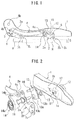
Fig. 1 is a schematic side view of a height adjusting device for an automobile seat according to an embodiment of the present invention; -
Fig. 2 is a schematic exploded perspective view of an actuating mechanism of the height adjusting device according to the embodiment of the present invention; -
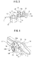
Fig. 3 is a schematic sectional view of the actuating mechanism ofFig. 2 in an assembled state; -
Fig. 4 is a schematic perspective view of the actuating mechanism ofFig. 2 in the assembled state; and -
Fig. 5 is a schematic perspective view of a spring-retaining member employed in the actuating mechanism shown inFig. 2 . - A height adjusting device for an automobile seat according to an embodiment of the present invention will be discussed hereinafter with reference to the drawings. In the illustrated example, the height adjusting device is to be provided at an assistant seat which is employed in an automobile having a steering wheel on the right side of an automobile body. The automobile seat includes a frame for a seat cushion, the frame including a pair of spaced apart side frame sections, and a slide rail mechanism for allowing an entire seat to be moved in a forward/rearward direction in the automobile body, the slide rail mechanism including a pair of spaced apart lower rail members and a pair of spaced apart upper rail members slidably supported to said lower rail members so as to be slidable along the lower rail members. The height adjusting device includes an operation knob for operating an actuating mechanism of the height adjusting device. The operation knob is arranged outside one of the spaced apart side frame sections. In the drawings, only one of the spaced apart side frame sections, only one of the spaced apart lower rail members, and only one of the spaced apart upper rail members are shown. More particularly, a side frame section, a lower rail member, and an upper rail member which are arranged on the side at which the operation knob is not arranged are mainly omitted from the illustration, and a side frame section, a lower rail member, and an upper rail member which are arranged on the side at which the operation knob is arranged are mainly shown in the drawings. In the illustrated example, the operation knob is arranged outside a side of a forward portion of a left side frame section of the seat cushion frame.
- Referring to
Fig. 1 , the height adjusting device is provided at the slide-type seat in which an entire seat comprising the seat cushion and a seat back can be moved in the forward/rearward direction along the spaced apart lower rail members R of the slide rail mechanism S which are installed on an automobile body floor. Each of the spaced apart upper rail members A is provided with spaced apart base brackets B1, B2 which are spaced apart from each other in a longitudinal direction of the upper rail member A and rise up from the upper rail member A. - The height adjusting device includes two pairs of forward and rearward
linkage arms forward linkage arms 2 being arranged between corresponding one of the side frame sections 1 and the forward base bracket B1 of corresponding one of the upper rail members A, each of the rearwardlinkage arms 3 being arranged between corresponding one of the side frame sections 1 and the rearward base bracket B2 of corresponding one of the upper rail members A, a linkage rod 4 connected between each of theforward linkage arms 2 and each of the rearwardlinkage arms 3, afirst connection shaft 5 interconnecting theforward linkage arms 2, asecond connection shaft 6 interconnecting therearward linkage arms 3, and the actuating mechanism. - Each of the
forward linkage arms 2 is supported at a substantially middle portion thereof to the corresponding side frame section 1 by afixing pin 2a. Similarly, each of therearward linkage arms 3 is supported at a substantially middle portion thereof to the corresponding side frame section 1 by afixing pin 3a. Moreover, each of theforward linkage arms 2 is pivotally supported at a lower end portion thereof to a corresponding base bracket B1 by a support pin 2b and each of the rearwardlinkage arms 3 is pivotally supported at a lower end portion thereof to a corresponding base bracket B2 by asupport pin 3b. The linkage rod 4 arranged on the side at which the operation knob is not arranged is connected at a forward end portion thereof to an upper end portion of a correspondingforward linkage arm 2 by asupport pin 4a and connected a rearward end portion thereof to an upper end portion of a correspondingrearward linkage arm 3 by asupport pin 4b. The linkage rod 4 arranged on the side at which the operation knob is arranged is connected at a forward end portion thereof to an upper end portion of a correspondingforward linkage arm 2 by a planting pin 16 (seeFig. 2 ) which will be discussed hereinafter, and connected at a rearward end portion thereof to an upper end portion of a correspondingrearward linkage arm 3 by asupport pin 4b. - Referring now to
Figs. 2 and3 , the actuating mechanism includes theoperation knob 10 arranged outside the left side frame section 1 with a rotatingshaft 11 thereof being rotatably penetrated the left side frame section 1, apinion gear 12 mounted around the rotatingshaft 11, asector gear 13 meshed with thepinion gear 12, and aspiral spring 14 for directly pulling a linkage rod 4 which is arranged on the side at which the operating knob is arranged. A different spiral spring may be applied to the forward linkage arm and/or the rearward linkage arm which is arranged on the side at which the operation knob is not arranged. - As the
operation knob 10, there may be employed a dial-type or lever-type operation knob. The left side frame section 1 at which theoperation knob 10 is arranged includes ahousing portion 1a which is formed by causing a portion of the left side frame section 1 to be embossed inward from a surface of the left side frame section 1 and has a substantially dome-shape in outline. The rotatingshaft 11 of theoperation knob 10 is rotatably penetrated through a top of the substantially dome-shaped housing portion 1 a with thepinion gear 12 mounted around the rotatingshaft 11 being received in thehousing portion 1a. Abrake section 15 is applied and fixed onto an outer surface of the left side frame section 1 so as to surround the rotatingshaft 11. The substantially dome-shaped housing portion 1a is formed with a notch (not shown) through which thepinion gear 12 and thesector gear 13 arranged inside the left side frame section 1 are meshed with each other. - The
sector gear 13 is arranged between the left side frame section 1 and the correspondingforward linkage arm 2 with abase portion 13a thereof being supported by thefixing pin 2a of theforward linkage arm 2. Theplanting pin 16 which has been briefly discussed above is protrusively provided on a corner portion of thesector gear 13 which isadjacent gear teeth 13b of thesector gear 13 and offset from thefixing pin 2a. Theforward linkage arm 2 and the linkage rod 4 which are shown inFig. 2 and arranged adjacent the first side frame section are connected to each other by theplanting pin 16. Thefixing pin 2a of theforward linkage arm 2 is fixed to the left side frame section 1 by riveting. Similarly, the plantingpin 16 is fixed to thesector gear 13 by riveting. - In
Fig. 2 , areference numeral 1b denotes a through-hole which is formed in the left side frame section 1 and through which thefixing pin 2a is inserted, areference numeral 2c denotes a through-hole which is formed in theforward linkage arm 2 and through which the support pin 2b for interconnecting the lower end portion of theforward linkage arm 2 and the base bracket B1 is inserted, areference numeral 2d designates a fixing hole which is formed in theforward linkage arm 2 and in which an end of thefirst connection shaft 5 interconnecting theforward linkage arms 2 is inserted, areference numeral 2e denotes a through-hole which is formed in theforward linkage arm 2 and through which theplanting pin 16 of thesector gear 13 is inserted, areference numeral 4c designates a through-hole which is formed in the linkage rod 4 and through which theplanting pin 16 is inserted, areference numeral 13c denotes a through-hole which is formed in the base portion of thesector gear 13 and through which thefixing pin 2a is inserted, and areference numeral 17 denotes a spacer which is fitted on the fixingpin 2a and arranged between the left side frame section 1 and thesector gear 13. - Referring to
Fig. 4 , thespiral spring 14 is retained at aninnermost end portion 14a thereof around the fixingpin 2a which is penetrated through the substantially middle portion of theforward linkage arm 2, and retained at anoutermost end portion 14b thereof around theplanting pin 16 which is penetrated through a connection portion between theforward linkage arm 2 and the linkage rod 4, so that theforward linkage arm 2 is biased in a rising-up direction by thespiral spring 14. Theinnermost end portion 14a of thespiral spring 14 may be retained to a spring-retainingmember 18 which is protruded from an end of the fixingpin 2a. Theoutermost end portion 14b of thespiral spring 14 is retained to a small diameter axial-portion (seeFig. 2 ) of theplanting pin 16. - Referring to
Fig. 5 , the spring-retainingmember 18 includes a substantially cup-shapedbase portion 18a, a narrow-width extension portion 18b of a substantially arc-shape in cross-section rising up from a region of a peripheral edge of the substantially cup-shapedbase portion 18a, and astopper portion 18c of a substantially arc-shaped in cross-section provided at an end of the narrow-width extension portion 18b and extending laterally with respect to the narrow-width extension portion 18b. The end of the fixingpin 2a is fitted through a through-hole formed in the substantially cup-shapedbase portion 18a and secured to thebase portion 18a by riveting. Theinnermost end portion 14a of thespiral spring 14 is retained around the narrow-width extension portion 18b and engaged with the laterally extendingstopper portion 18c so as not to be unwound from the narrow-width extension portion 18b. - In the height adjusting device constructed as discussed above, when the
operation knob 10 is rotated in a counterclockwise direction in a case where the entire seat is located in a lower position, thepinion gear 12 is rotated in the same direction. Simultaneously with the rotation of thepinion gear 12, thesector gear 13 which is meshed with thepinion gear 12 is rotated in a clockwise direction. As thesector gear 13 is rotated, theplanting pin 16 of thesector gear 13 which is arranged at a location which is offset from the fixingpin 2a is moved so as to cause theforward linkage arm 2 to be pivoted upward. Simultaneously, the linkage rod 4 which is connected to theforward linkage arm 2 is forward drawn and therearward linkage arm 2 is also pivoted upward. - Synchronously with such movements of the
forward linkage arm 2, the linkage rod 4, and therearward linkage arm 3, the unshown forward linkage arm, the unshown linkage rod, and the unshown rearward linkage arm are moved in the same manners as theforward linkage arm 2, the linkage rod 4, and therearward linkage arm 3 which are shown inFig. 4 are done, respectively. Thus, the entire seat can be lifted up by the height adjusting device. When the operation knob is rotated in a clockwise direction, the forward linkage arms are pivoted so as to be collapsed, the linkage rods are drawn rearward, and the rearward linkage arms are also pivoted so as to be collapsed. In this way, the entire can be lowered by the height adjusting device. - In the illustrated embodiment, the fixing
pin 2a of theforward linkage arm 2 which is shown inFig. 2 is also used as a support pin for thesector gear 13, and theplanting pin 16 of thesector gear 13 is used for a connection pin which interconnects theforward linkage arm 2 and the linkage rod 4, so that reduction of the number of parts of the height adjusting device, reduction of time to be required for assembling of the height adjusting device, and reduction of the assembling cost of the height adjusting device can be realized. - Moreover, the
spiral spring 14 is retained at theinnermost end portion 14a thereof to the spring-retainingmember 18 attached to the end of the fixingpin 2a which is projected from the substantially middle portion of theforward linkage arm 2, and retained at theoutermost end portion 14b thereof to theplanting pin 16 which is penetrated through the connection portion between theforward linkage arm 2 and the linkage rod 4, so that after-attaching of thespiral spring 14 can be carried out. Thus, a peripheral structure around the sections to which thespiral spring 14 is applied can be simplified, and replacement of the spiral spring can be easily carried out. - In the illustrated example, the
innermost end portion 14a of thespiral spring 14 is retained around the narrow-width extension portion 18b of the spring-retainingmember 18 and theoutermost end portion 14b of thespiral spring 14 is retained around theplanting pin 16, so that even if there is a limitation on an offset amount between the fixingpin 2a and theplanting pin 16, the spiral spring of a large spring constant can be employed. Therefore, by causing the operation knob to be rotated with small power, the seat can be vertically moved, thus making it possible to improve operability of the height adjusting device. - While the case where the actuating mechanism is arranged at the forward portion of the side frame section has been discussed above in connection with the embodiment of the present invention, the actuating mechanism may be arranged at a rearward portion of the side frame section.
- The terms and expressions which have been employed are used as terms of description and not of limitation, and there is no intention in the use of such terms and expressions of excluding any equivalents of the features shown and described, or portions thereof, but it is recognized that various modifications are possible within the scope of the invention claimed.
Claims (2)
- A height adjusting device for an automobile seat, said automobile seat including a seat cushion frame having a pair of first and second spaced apart side frame sections, and first and second pairs of spaced apart base brackets, said height adjusting device comprising:a pair of first and second forward linkage arms;said first forward linkage arm being bridged between said first side frame section and corresponding one of said first pair of spaced apart brackets and supported at a substantially middle portion thereof to said first side frame section by a fixing pin;said second forward linkage arm being bridged between said second side frame section and the other of said first pair of spaced apart brackets and supported at a substantially middle portion thereof to said second side frame section;a pair of first and second rearward linkage arms;said first rearward linkage arm being bridged between said first side frame section and corresponding one of said second pair of spaced apart brackets and supported at a substantially middle portion thereof to said first side frame section;said second rearward linkage arm being bridged between said second side frame section and the other of said second pair of spaced apart brackets and supported at a substantially middle portion thereof to said second side frame section;a first linkage rod connected at a forward end and a rearward end thereof to an upper end of said first forward linkage arm and an upper end of said first rearward linkage arm;a second linkage rod connected at a forward end and a rearward end thereof to an upper end of said second forward linkage arm and an upper end of said second rearward linkage arm;a first connection shaft interconnecting said forward linkage arms;a second connection shaft interconnecting said rearward linkage arms; andan actuating mechanism for causing said forward and rearward linkage arms to be vertically pivoted;said actuating mechanism including:an operation knob having a rotating shaft;said operation knob being arranged outside said first side frame section with said rotating shaft being rotatably penetrated through said first side frame section;a pinion gear mounted around said rotating shaft;a sector gear for directly drawing said first linkage rod;said sector gear being arranged inside said first side frame section and meshed with said pinion gear; anda spiral spring for directly biasing said first forward linkage arm in a rising-up direction;said sector gear being arranged between said first side frame section and said first forward linkage arm and supported at a base portion thereof to said fixing pin of said first forward linkage arm;said sector gear having a planting pin provided at a corner portion thereof adjacent gear teeth thereof so as to be projected from said sector gear;said first forward linkage arm and said first linkage rod being connected to each other by said fixing pin; andsaid spiral spring being stretched between said fixing pin and said planting pin with an innermost end portion thereof being retained around an end of said fixing pin which is projected inward from said first forward linkage arm, and with an outermost end portion thereof being retained around an end of said planting pin which is projected inward from a connection portion between said first forward linkage arm and said first linkage rod.
- A height adjusting device according to claim 1, wherein said spiral spring has a large spring constant, and said fixing pin is provided at said end thereof with a spring-retaining member, said innermost end portion of said spiral spring being retained to said spring-retaining member.
Applications Claiming Priority (2)
| Application Number | Priority Date | Filing Date | Title |
|---|---|---|---|
| JP2006139950A JP4883441B2 (en) | 2006-05-19 | 2006-05-19 | Automotive seat height adjustment device |
| PCT/JP2007/060659 WO2007136120A1 (en) | 2006-05-19 | 2007-05-18 | Device for adjusting height of automobile seat |
Publications (3)
| Publication Number | Publication Date |
|---|---|
| EP2062772A1 true EP2062772A1 (en) | 2009-05-27 |
| EP2062772A4 EP2062772A4 (en) | 2010-01-27 |
| EP2062772B1 EP2062772B1 (en) | 2012-04-11 |
Family
ID=38723429
Family Applications (1)
| Application Number | Title | Priority Date | Filing Date |
|---|---|---|---|
| EP07744093A Not-in-force EP2062772B1 (en) | 2006-05-19 | 2007-05-18 | Automobile seat with height adjusting device |
Country Status (4)
| Country | Link |
|---|---|
| US (1) | US7828384B2 (en) |
| EP (1) | EP2062772B1 (en) |
| JP (1) | JP4883441B2 (en) |
| WO (1) | WO2007136120A1 (en) |
Cited By (3)
| Publication number | Priority date | Publication date | Assignee | Title |
|---|---|---|---|---|
| WO2016074871A1 (en) * | 2014-11-13 | 2016-05-19 | Johnson Controls Gmbh | Connecting element |
| CN106314218A (en) * | 2016-10-27 | 2017-01-11 | 上海延锋江森座椅机械部件有限公司 | Manual seat height adjusting device based on 3Z gear mechanism |
| DE102010036346B4 (en) | 2010-07-12 | 2020-07-02 | Dr. Ing. H.C. F. Porsche Aktiengesellschaft | Vehicle seat |
Families Citing this family (33)
| Publication number | Priority date | Publication date | Assignee | Title |
|---|---|---|---|---|
| TWM357248U (en) * | 2008-12-16 | 2009-05-21 | Red Heart Entpr Co Ltd | Welfare seat equipment and seat moving device |
| DE112009004986T5 (en) * | 2009-06-10 | 2013-05-02 | Lear Corporation | Vehicle seat with pivotally connected joint element |
| WO2012049726A1 (en) * | 2010-10-12 | 2012-04-19 | テイ・エス テック株式会社 | Vehicle seat |
| KR101582692B1 (en) * | 2009-11-18 | 2016-01-05 | 주식회사다스 | Pumping ball type seat height fixing device |
| JP5684736B2 (en) * | 2010-01-21 | 2015-03-18 | シロキ工業株式会社 | Stepped lowering device and stepped lifter device |
| JP5434641B2 (en) * | 2010-02-03 | 2014-03-05 | トヨタ紡織株式会社 | Vehicle seat |
| JP5218506B2 (en) * | 2010-09-17 | 2013-06-26 | アイシン精機株式会社 | Seat lifter device |
| DE112011103438T5 (en) | 2010-10-12 | 2013-08-14 | Ts Tech Co., Ltd. | vehicle seat |
| US8596721B2 (en) * | 2011-02-17 | 2013-12-03 | Tachi-S Co., Ltd. | Vehicle seat |
| DE102011001638A1 (en) * | 2011-03-29 | 2012-10-04 | C. Rob. Hammerstein Gmbh & Co. Kg | Undercarriage for a motor vehicle seat |
| JP2012254777A (en) * | 2011-05-19 | 2012-12-27 | Shiroki Corp | Seat lifter |
| US9151644B2 (en) | 2011-07-28 | 2015-10-06 | Ts Tech Co., Ltd. | Load measurement sensor support structure |
| US9352666B2 (en) | 2011-08-10 | 2016-05-31 | Ts Tech Co., Ltd. | Vehicle seat |
| US20140224553A1 (en) * | 2011-08-10 | 2014-08-14 | Ts Tech Co., Ltd. | Load measurement sensor support structure |
| ITMI20112152A1 (en) * | 2011-11-25 | 2013-05-26 | Sabelt Spa | ADJUSTABLE SEAT FOR MOTOR VEHICLES |
| DE102011122275A1 (en) * | 2011-12-23 | 2013-06-27 | Gm Global Technology Operations, Llc | Adjusting device for adjusting seat height of motor car, has first gear and/or first toothed arc that are formed as separate sheet from pivotable arm by operation of second gear and/or second toothed arc of pivotable arm |
| US20130175841A1 (en) | 2012-01-11 | 2013-07-11 | James W. Finck | Reclining seat assembly |
| JP5933018B2 (en) * | 2012-09-21 | 2016-06-08 | テイ・エス テック株式会社 | Vehicle seat |
| DE102013001416B4 (en) | 2013-01-24 | 2019-02-07 | Adient Luxembourg Holding S.À R.L. | Height adjuster for a vehicle seat and vehicle seat |
| JP6237468B2 (en) * | 2013-06-10 | 2017-11-29 | トヨタ紡織株式会社 | Vehicle seat |
| WO2015008713A1 (en) * | 2013-07-14 | 2015-01-22 | 株式会社デルタツーリング | Lifter mechanism and vehicular seat |
| CN103655020B (en) * | 2013-12-29 | 2015-07-08 | 宁波市鄞州云帆工程咨询有限公司 | Axial rotation multi-pin locking type traction height control mechanism |
| DE102014102095A1 (en) * | 2014-02-19 | 2015-08-20 | GNS-KV GmbH | Seat height adjustment module and arrangement for height adjustment of a seat |
| JP2017065484A (en) * | 2015-09-30 | 2017-04-06 | アイシン精機株式会社 | Vehicle seat lifter |
| JP6668947B2 (en) * | 2016-05-26 | 2020-03-18 | トヨタ紡織株式会社 | Vehicle seat |
| DE102016112106B4 (en) * | 2016-07-01 | 2019-07-04 | Grammer Ag | suspension device |
| DE102016112105A1 (en) * | 2016-07-01 | 2018-01-04 | Grammer Ag | suspension device |
| US10569670B2 (en) * | 2018-03-16 | 2020-02-25 | Adient Engineering and IP GmbH | Seat lifter structure and vehicle seat equipped with the same |
| KR102108803B1 (en) | 2018-03-22 | 2020-05-11 | 현대자동차주식회사 | Vehicle seat and method for adjusting sitting position using vehicle seat |
| KR102602914B1 (en) * | 2018-11-26 | 2023-11-16 | 현대자동차주식회사 | Seat height adjust apparatus for vehicle seat |
| CN112483818B (en) * | 2020-11-17 | 2025-02-21 | 深圳市蓝禾技术有限公司 | Multi-speed adjustment structure and electronic equipment bracket |
| GB202106869D0 (en) | 2021-05-13 | 2021-06-30 | Mclaren Automotive Ltd | Seat adjustment mechanism |
| JP7740019B2 (en) * | 2021-12-28 | 2025-09-17 | トヨタ紡織株式会社 | Vehicle seats |
Family Cites Families (13)
| Publication number | Priority date | Publication date | Assignee | Title |
|---|---|---|---|---|
| AU558012B2 (en) * | 1983-12-06 | 1987-01-15 | Tachikawa Spring Co. Ltd. | Seat frame for vehicle seat |
| JPH10129322A (en) | 1996-10-31 | 1998-05-19 | Tachi S Co Ltd | Suspension device for vehicle seat |
| JP4161355B2 (en) * | 1998-09-16 | 2008-10-08 | アイシン精機株式会社 | Vehicle seat lifter |
| JP2000108734A (en) | 1998-10-08 | 2000-04-18 | Fuji Heavy Ind Ltd | Seat height adjustment device |
| US6095475A (en) | 1998-10-23 | 2000-08-01 | Dura Automtive Properties Inc. | Manual height adjustment assembly for a vehicle seat |
| JP4499856B2 (en) | 1999-11-11 | 2010-07-07 | 富士機工株式会社 | Seat height adjustment device |
| JP4551029B2 (en) * | 2001-06-27 | 2010-09-22 | デルタ工業株式会社 | Seat lift equipment |
| JP4040910B2 (en) | 2002-05-31 | 2008-01-30 | 富士機工株式会社 | Seat lifter stopper structure |
| JP2004284387A (en) * | 2003-03-19 | 2004-10-14 | Fuji Kiko Co Ltd | Structure to reduce operation force of seat lifter |
| JP2006199049A (en) * | 2003-04-21 | 2006-08-03 | T S Tec Kk | Height-adjusting device for automobile seat |
| JP2006182039A (en) * | 2003-04-21 | 2006-07-13 | T S Tec Kk | Height adjusting device for car seat |
| JP4621948B2 (en) * | 2004-06-30 | 2011-02-02 | テイ・エス テック株式会社 | Retainer for spring end stop |
| JP2008087554A (en) * | 2006-09-29 | 2008-04-17 | Aisin Seiki Co Ltd | Vehicle seat device |
-
2006
- 2006-05-19 JP JP2006139950A patent/JP4883441B2/en not_active Expired - Lifetime
-
2007
- 2007-05-18 EP EP07744093A patent/EP2062772B1/en not_active Not-in-force
- 2007-05-18 WO PCT/JP2007/060659 patent/WO2007136120A1/en not_active Ceased
- 2007-05-18 US US12/301,537 patent/US7828384B2/en not_active Expired - Fee Related
Cited By (5)
| Publication number | Priority date | Publication date | Assignee | Title |
|---|---|---|---|---|
| DE102010036346B4 (en) | 2010-07-12 | 2020-07-02 | Dr. Ing. H.C. F. Porsche Aktiengesellschaft | Vehicle seat |
| WO2016074871A1 (en) * | 2014-11-13 | 2016-05-19 | Johnson Controls Gmbh | Connecting element |
| US10239422B2 (en) | 2014-11-13 | 2019-03-26 | Adient Luxembourg Holding S.à.r.l. | Connecting element |
| CN106314218A (en) * | 2016-10-27 | 2017-01-11 | 上海延锋江森座椅机械部件有限公司 | Manual seat height adjusting device based on 3Z gear mechanism |
| CN106314218B (en) * | 2016-10-27 | 2018-08-17 | 延锋安道拓座椅机械部件有限公司 | Manual seat height-regulating device based on 3Z gear mechanisms |
Also Published As
| Publication number | Publication date |
|---|---|
| JP2007308050A (en) | 2007-11-29 |
| US20100001569A1 (en) | 2010-01-07 |
| WO2007136120A1 (en) | 2007-11-29 |
| EP2062772A4 (en) | 2010-01-27 |
| EP2062772B1 (en) | 2012-04-11 |
| JP4883441B2 (en) | 2012-02-22 |
| US7828384B2 (en) | 2010-11-09 |
Similar Documents
| Publication | Publication Date | Title |
|---|---|---|
| EP2062772B1 (en) | Automobile seat with height adjusting device | |
| JP5187119B2 (en) | Control lever structure for vehicle seat | |
| JP6393105B2 (en) | Vehicle seat | |
| US9415714B2 (en) | Lumber support apparatus for vehicle | |
| US20180050616A1 (en) | Seat reclining apparatus | |
| WO2006104288A1 (en) | Seat height adjustment device for automobile | |
| US20060091711A1 (en) | Vehicle seat apparatus | |
| JP2023075318A (en) | vehicle seat | |
| JP6334307B2 (en) | Vehicle seat | |
| KR101470223B1 (en) | Apparatus for seat side bolster of vehicle | |
| JP2014148216A (en) | Seat device | |
| JP2009227011A (en) | Seat with manually height adjusting mechanism | |
| JP5239031B2 (en) | Rear seat device | |
| JP2025027043A (en) | Vehicle seat | |
| JP5470950B2 (en) | Sheet position shape change device | |
| JP2010095178A (en) | Vehicle seat | |
| JP2010246805A (en) | Vehicle seat | |
| JP5219559B2 (en) | Electric leg support device | |
| KR102281636B1 (en) | Seat cushion extension apparatus and seat cushion comprising the same | |
| JP4122444B2 (en) | Vehicle seat device | |
| JP2018027750A (en) | Drive device of vehicle seat | |
| JP4899205B2 (en) | Automotive seat height adjustment device | |
| JP5844968B2 (en) | Reclining device | |
| JP2007062530A (en) | Vertical adjustment device for vehicle seat | |
| JP2931452B2 (en) | Power type headrest structure |
Legal Events
| Date | Code | Title | Description |
|---|---|---|---|
| PUAI | Public reference made under article 153(3) epc to a published international application that has entered the european phase |
Free format text: ORIGINAL CODE: 0009012 |
|
| 17P | Request for examination filed |
Effective date: 20081217 |
|
| AK | Designated contracting states |
Kind code of ref document: A1 Designated state(s): AT BE BG CH CY CZ DE DK EE ES FI FR GB GR HU IE IS IT LI LT LU LV MC MT NL PL PT RO SE SI SK TR |
|
| AX | Request for extension of the european patent |
Extension state: AL BA HR MK RS |
|
| A4 | Supplementary search report drawn up and despatched |
Effective date: 20091228 |
|
| 17Q | First examination report despatched |
Effective date: 20100408 |
|
| RTI1 | Title (correction) |
Free format text: AUTOMOBILE SEAT WITH HEIGHT ADJUSTING DEVICE |
|
| DAX | Request for extension of the european patent (deleted) | ||
| RBV | Designated contracting states (corrected) |
Designated state(s): DE FR GB |
|
| GRAP | Despatch of communication of intention to grant a patent |
Free format text: ORIGINAL CODE: EPIDOSNIGR1 |
|
| RBV | Designated contracting states (corrected) |
Designated state(s): DE FR GB |
|
| DAX | Request for extension of the european patent (deleted) | ||
| GRAS | Grant fee paid |
Free format text: ORIGINAL CODE: EPIDOSNIGR3 |
|
| GRAA | (expected) grant |
Free format text: ORIGINAL CODE: 0009210 |
|
| DAX | Request for extension of the european patent (deleted) | ||
| RBV | Designated contracting states (corrected) |
Designated state(s): DE FR GB |
|
| AK | Designated contracting states |
Kind code of ref document: B1 Designated state(s): DE FR GB |
|
| REG | Reference to a national code |
Ref country code: GB Ref legal event code: FG4D |
|
| REG | Reference to a national code |
Ref country code: DE Ref legal event code: R096 Ref document number: 602007021921 Country of ref document: DE Effective date: 20120606 |
|
| PLBE | No opposition filed within time limit |
Free format text: ORIGINAL CODE: 0009261 |
|
| STAA | Information on the status of an ep patent application or granted ep patent |
Free format text: STATUS: NO OPPOSITION FILED WITHIN TIME LIMIT |
|
| 26N | No opposition filed |
Effective date: 20130114 |
|
| REG | Reference to a national code |
Ref country code: DE Ref legal event code: R097 Ref document number: 602007021921 Country of ref document: DE Effective date: 20130114 |
|
| REG | Reference to a national code |
Ref country code: FR Ref legal event code: PLFP Year of fee payment: 9 |
|
| PGFP | Annual fee paid to national office [announced via postgrant information from national office to epo] |
Ref country code: GB Payment date: 20150513 Year of fee payment: 9 Ref country code: DE Payment date: 20150512 Year of fee payment: 9 |
|
| REG | Reference to a national code |
Ref country code: DE Ref legal event code: R082 Ref document number: 602007021921 Country of ref document: DE Representative=s name: GRAMM, LINS & PARTNER PATENT- UND RECHTSANWAEL, DE |
|
| PGFP | Annual fee paid to national office [announced via postgrant information from national office to epo] |
Ref country code: FR Payment date: 20150508 Year of fee payment: 9 |
|
| REG | Reference to a national code |
Ref country code: DE Ref legal event code: R119 Ref document number: 602007021921 Country of ref document: DE |
|
| GBPC | Gb: european patent ceased through non-payment of renewal fee |
Effective date: 20160518 |
|
| REG | Reference to a national code |
Ref country code: FR Ref legal event code: ST Effective date: 20170131 |
|
| PG25 | Lapsed in a contracting state [announced via postgrant information from national office to epo] |
Ref country code: DE Free format text: LAPSE BECAUSE OF NON-PAYMENT OF DUE FEES Effective date: 20161201 Ref country code: FR Free format text: LAPSE BECAUSE OF NON-PAYMENT OF DUE FEES Effective date: 20160531 |
|
| PG25 | Lapsed in a contracting state [announced via postgrant information from national office to epo] |
Ref country code: GB Free format text: LAPSE BECAUSE OF NON-PAYMENT OF DUE FEES Effective date: 20160518 |