EP2061644B1 - Method of manufacturing composite material by growing of a layer of reinforcement and related apparatus - Google Patents
Method of manufacturing composite material by growing of a layer of reinforcement and related apparatus Download PDFInfo
- Publication number
- EP2061644B1 EP2061644B1 EP07789385A EP07789385A EP2061644B1 EP 2061644 B1 EP2061644 B1 EP 2061644B1 EP 07789385 A EP07789385 A EP 07789385A EP 07789385 A EP07789385 A EP 07789385A EP 2061644 B1 EP2061644 B1 EP 2061644B1
- Authority
- EP
- European Patent Office
- Prior art keywords
- layer
- reinforcement
- matrix
- composite material
- growing
- Prior art date
- Legal status (The legal status is an assumption and is not a legal conclusion. Google has not performed a legal analysis and makes no representation as to the accuracy of the status listed.)
- Not-in-force
Links
- 230000002787 reinforcement Effects 0.000 title claims abstract description 56
- 239000002131 composite material Substances 0.000 title claims abstract description 27
- 238000004519 manufacturing process Methods 0.000 title claims abstract description 26
- 238000000034 method Methods 0.000 claims abstract description 47
- 239000011159 matrix material Substances 0.000 claims abstract description 43
- 238000000465 moulding Methods 0.000 claims abstract description 4
- 239000003054 catalyst Substances 0.000 claims description 32
- 239000002245 particle Substances 0.000 claims description 32
- OKTJSMMVPCPJKN-UHFFFAOYSA-N Carbon Chemical compound [C] OKTJSMMVPCPJKN-UHFFFAOYSA-N 0.000 claims description 15
- 239000000843 powder Substances 0.000 claims description 12
- 238000012856 packing Methods 0.000 claims description 10
- 230000005672 electromagnetic field Effects 0.000 claims description 9
- 238000005470 impregnation Methods 0.000 claims description 8
- 229910052799 carbon Inorganic materials 0.000 claims description 6
- 238000000151 deposition Methods 0.000 claims description 5
- 238000010438 heat treatment Methods 0.000 claims description 5
- 230000001154 acute effect Effects 0.000 claims description 4
- 239000010410 layer Substances 0.000 description 134
- 230000008569 process Effects 0.000 description 16
- 239000000463 material Substances 0.000 description 13
- 238000007639 printing Methods 0.000 description 13
- 229920000642 polymer Polymers 0.000 description 12
- 239000002041 carbon nanotube Substances 0.000 description 9
- 229910021393 carbon nanotube Inorganic materials 0.000 description 9
- 239000000084 colloidal system Substances 0.000 description 9
- 239000002071 nanotube Substances 0.000 description 9
- 238000011065 in-situ storage Methods 0.000 description 8
- 239000007789 gas Substances 0.000 description 7
- 239000011261 inert gas Substances 0.000 description 7
- 239000007788 liquid Substances 0.000 description 7
- 229920005989 resin Polymers 0.000 description 7
- 239000011347 resin Substances 0.000 description 7
- 230000007246 mechanism Effects 0.000 description 5
- 229910052751 metal Inorganic materials 0.000 description 5
- 239000002184 metal Substances 0.000 description 5
- 229920001169 thermoplastic Polymers 0.000 description 5
- 239000004696 Poly ether ether ketone Substances 0.000 description 4
- 229920002530 polyetherether ketone Polymers 0.000 description 4
- 239000000758 substrate Substances 0.000 description 4
- 229920001187 thermosetting polymer Polymers 0.000 description 4
- 239000004416 thermosoftening plastic Substances 0.000 description 4
- 238000009792 diffusion process Methods 0.000 description 3
- 238000010891 electric arc Methods 0.000 description 3
- 238000000608 laser ablation Methods 0.000 description 3
- 239000002356 single layer Substances 0.000 description 3
- 239000002002 slurry Substances 0.000 description 3
- 239000000725 suspension Substances 0.000 description 3
- 230000007723 transport mechanism Effects 0.000 description 3
- LFQSCWFLJHTTHZ-UHFFFAOYSA-N Ethanol Chemical compound CCO LFQSCWFLJHTTHZ-UHFFFAOYSA-N 0.000 description 2
- 239000000654 additive Substances 0.000 description 2
- 230000000996 additive effect Effects 0.000 description 2
- 239000003990 capacitor Substances 0.000 description 2
- 238000011960 computer-aided design Methods 0.000 description 2
- 230000005684 electric field Effects 0.000 description 2
- 239000012530 fluid Substances 0.000 description 2
- 238000002844 melting Methods 0.000 description 2
- 230000008018 melting Effects 0.000 description 2
- 239000002114 nanocomposite Substances 0.000 description 2
- 239000002121 nanofiber Substances 0.000 description 2
- 239000003921 oil Substances 0.000 description 2
- 239000007921 spray Substances 0.000 description 2
- 238000005507 spraying Methods 0.000 description 2
- XLYOFNOQVPJJNP-UHFFFAOYSA-N water Substances O XLYOFNOQVPJJNP-UHFFFAOYSA-N 0.000 description 2
- RTAQQCXQSZGOHL-UHFFFAOYSA-N Titanium Chemical compound [Ti] RTAQQCXQSZGOHL-UHFFFAOYSA-N 0.000 description 1
- 238000009825 accumulation Methods 0.000 description 1
- 230000009471 action Effects 0.000 description 1
- 239000000956 alloy Substances 0.000 description 1
- 229910045601 alloy Inorganic materials 0.000 description 1
- PNEYBMLMFCGWSK-UHFFFAOYSA-N aluminium oxide Inorganic materials [O-2].[O-2].[O-2].[Al+3].[Al+3] PNEYBMLMFCGWSK-UHFFFAOYSA-N 0.000 description 1
- 229910003481 amorphous carbon Inorganic materials 0.000 description 1
- 238000010923 batch production Methods 0.000 description 1
- 238000009835 boiling Methods 0.000 description 1
- 239000013590 bulk material Substances 0.000 description 1
- 239000011203 carbon fibre reinforced carbon Substances 0.000 description 1
- 238000012512 characterization method Methods 0.000 description 1
- 238000005229 chemical vapour deposition Methods 0.000 description 1
- 238000009833 condensation Methods 0.000 description 1
- 230000005494 condensation Effects 0.000 description 1
- 238000010924 continuous production Methods 0.000 description 1
- 238000001816 cooling Methods 0.000 description 1
- 239000006185 dispersion Substances 0.000 description 1
- 238000009826 distribution Methods 0.000 description 1
- 230000000694 effects Effects 0.000 description 1
- 239000003822 epoxy resin Substances 0.000 description 1
- 239000010408 film Substances 0.000 description 1
- 238000007641 inkjet printing Methods 0.000 description 1
- 239000011229 interlayer Substances 0.000 description 1
- 239000004850 liquid epoxy resins (LERs) Substances 0.000 description 1
- 239000000203 mixture Substances 0.000 description 1
- 238000012986 modification Methods 0.000 description 1
- 230000004048 modification Effects 0.000 description 1
- 239000002048 multi walled nanotube Substances 0.000 description 1
- 229910052759 nickel Inorganic materials 0.000 description 1
- 230000003647 oxidation Effects 0.000 description 1
- 238000007254 oxidation reaction Methods 0.000 description 1
- 229920000647 polyepoxide Polymers 0.000 description 1
- 230000001376 precipitating effect Effects 0.000 description 1
- 238000001556 precipitation Methods 0.000 description 1
- 238000012545 processing Methods 0.000 description 1
- 150000003839 salts Chemical class 0.000 description 1
- HBMJWWWQQXIZIP-UHFFFAOYSA-N silicon carbide Chemical compound [Si+]#[C-] HBMJWWWQQXIZIP-UHFFFAOYSA-N 0.000 description 1
- 229910010271 silicon carbide Inorganic materials 0.000 description 1
- 239000002109 single walled nanotube Substances 0.000 description 1
- 239000007787 solid Substances 0.000 description 1
- 239000012815 thermoplastic material Substances 0.000 description 1
- 239000010409 thin film Substances 0.000 description 1
- 229910052719 titanium Inorganic materials 0.000 description 1
- 239000010936 titanium Substances 0.000 description 1
- 229910052723 transition metal Inorganic materials 0.000 description 1
- 150000003624 transition metals Chemical class 0.000 description 1
- 239000011364 vaporized material Substances 0.000 description 1
Images


Classifications
-
- C—CHEMISTRY; METALLURGY
- C08—ORGANIC MACROMOLECULAR COMPOUNDS; THEIR PREPARATION OR CHEMICAL WORKING-UP; COMPOSITIONS BASED THEREON
- C08J—WORKING-UP; GENERAL PROCESSES OF COMPOUNDING; AFTER-TREATMENT NOT COVERED BY SUBCLASSES C08B, C08C, C08F, C08G or C08H
- C08J7/00—Chemical treatment or coating of shaped articles made of macromolecular substances
- C08J7/12—Chemical modification
- C08J7/123—Treatment by wave energy or particle radiation
-
- B—PERFORMING OPERATIONS; TRANSPORTING
- B29—WORKING OF PLASTICS; WORKING OF SUBSTANCES IN A PLASTIC STATE IN GENERAL
- B29C—SHAPING OR JOINING OF PLASTICS; SHAPING OF MATERIAL IN A PLASTIC STATE, NOT OTHERWISE PROVIDED FOR; AFTER-TREATMENT OF THE SHAPED PRODUCTS, e.g. REPAIRING
- B29C70/00—Shaping composites, i.e. plastics material comprising reinforcements, fillers or preformed parts, e.g. inserts
- B29C70/04—Shaping composites, i.e. plastics material comprising reinforcements, fillers or preformed parts, e.g. inserts comprising reinforcements only, e.g. self-reinforcing plastics
- B29C70/28—Shaping operations therefor
- B29C70/30—Shaping by lay-up, i.e. applying fibres, tape or broadsheet on a mould, former or core; Shaping by spray-up, i.e. spraying of fibres on a mould, former or core
-
- B—PERFORMING OPERATIONS; TRANSPORTING
- B33—ADDITIVE MANUFACTURING TECHNOLOGY
- B33Y—ADDITIVE MANUFACTURING, i.e. MANUFACTURING OF THREE-DIMENSIONAL [3-D] OBJECTS BY ADDITIVE DEPOSITION, ADDITIVE AGGLOMERATION OR ADDITIVE LAYERING, e.g. BY 3-D PRINTING, STEREOLITHOGRAPHY OR SELECTIVE LASER SINTERING
- B33Y10/00—Processes of additive manufacturing
-
- B—PERFORMING OPERATIONS; TRANSPORTING
- B82—NANOTECHNOLOGY
- B82Y—SPECIFIC USES OR APPLICATIONS OF NANOSTRUCTURES; MEASUREMENT OR ANALYSIS OF NANOSTRUCTURES; MANUFACTURE OR TREATMENT OF NANOSTRUCTURES
- B82Y30/00—Nanotechnology for materials or surface science, e.g. nanocomposites
-
- C—CHEMISTRY; METALLURGY
- C08—ORGANIC MACROMOLECULAR COMPOUNDS; THEIR PREPARATION OR CHEMICAL WORKING-UP; COMPOSITIONS BASED THEREON
- C08J—WORKING-UP; GENERAL PROCESSES OF COMPOUNDING; AFTER-TREATMENT NOT COVERED BY SUBCLASSES C08B, C08C, C08F, C08G or C08H
- C08J5/00—Manufacture of articles or shaped materials containing macromolecular substances
- C08J5/04—Reinforcing macromolecular compounds with loose or coherent fibrous material
- C08J5/0405—Reinforcing macromolecular compounds with loose or coherent fibrous material with inorganic fibres
- C08J5/042—Reinforcing macromolecular compounds with loose or coherent fibrous material with inorganic fibres with carbon fibres
-
- B—PERFORMING OPERATIONS; TRANSPORTING
- B29—WORKING OF PLASTICS; WORKING OF SUBSTANCES IN A PLASTIC STATE IN GENERAL
- B29C—SHAPING OR JOINING OF PLASTICS; SHAPING OF MATERIAL IN A PLASTIC STATE, NOT OTHERWISE PROVIDED FOR; AFTER-TREATMENT OF THE SHAPED PRODUCTS, e.g. REPAIRING
- B29C70/00—Shaping composites, i.e. plastics material comprising reinforcements, fillers or preformed parts, e.g. inserts
- B29C70/58—Shaping composites, i.e. plastics material comprising reinforcements, fillers or preformed parts, e.g. inserts comprising fillers only, e.g. particles, powder, beads, flakes, spheres
- B29C70/62—Shaping composites, i.e. plastics material comprising reinforcements, fillers or preformed parts, e.g. inserts comprising fillers only, e.g. particles, powder, beads, flakes, spheres the filler being oriented during moulding
Definitions
- the present invention relates to a method of manufacturing a composite material.
- Nanocomposites based on carbon nanotubes are described in E. T. Thostenson and T-W. Chou, "Aligned Multi-Walled Carbon Nanotube-Reinforced Composites: Processing and Mechanical Characterization," Journal of Physics D: Applied Physics, 35(16) L77-L80 (2002 ). According to this paper, one of the most significant challenges towards improving the properties of the nanocomposite is to obtain a uniform dispersion of nanotubes within the polymer matrix. The solution presented in this paper is a micro-scale twin-screw extruder.
- thermal interface material which includes a macromolecular material and a plurality of carbon nanotubes embedded in the macromolecular material uniformly.
- the thermal interface material includes a first surface and an opposite second surface.
- Each carbon nanotube is fixed to a substrate at one end and extends from the first surface to the second surface of the thermal interface material to optimise the thermal interface properties of the material.
- US4560603 describes a composite material manufacturing process and resulting structure.
- the composite material includes high strength material whiskers having a characteristic orientation when placed in an electromagnetic field.
- US2005/0061496 describes a thermal interface material in which carbon nanotubes are combines with an alignment material.
- the alignment material is aligned, which causes the carbon nanotubes to become aligned and efficiently conduct heat.
- US2003/0111333 describes a method and apparatus for producing aligned carbon nanotube thermal interface structures using batch and continuous manufacturing processes.
- a capacitor is immersed in a bath containing a slurry of thermoplastic polymer containing randomly oriented carbon nanotubes and energised to create an electric field to orient the nanotubes prior to curing.
- slurry carried by a conveyor receives the nanotube aligning electric field from capacitors positioned on both sides of the conveyor bearing the slurry.
- a first aspect of the invention provides a method of manufacturing a composite material, the method comprising:
- the field is applied at an angle to the reinforcement layer, either perpendicular or at an acute angle.
- Growth of the reinforcement layers may be enhanced by forming a plasma during growth of the layer. This enables growth to be carried out at lower temperatures, typically in the range of 25-500°C.
- a further aspect of the invention provides a method of manufacturing a composite material, the method comprising:
- a further aspect of the invention provides a method of manufacturing a composite material, the method comprising:
- a further aspect of the invention provides a method of manufacturing a composite material, the method comprising:
- a further aspect of the invention provides a method of manufacturing a composite material, the method comprising:
- This aspect of the invention may be used to form sheets (either single layer or multi-layer) which are processed in a similar manner to a conventional "prepreg", that is by laying the sheets together to form a laminate structure; and moulding the laminate structure to form a composite element.
- a further aspect of the invention provides apparatus for manufacturing a composite material, the apparatus comprising:
- a further aspect of the invention provides apparatus for manufacturing a composite material, the apparatus comprising:
- a further aspect of the invention provides apparatus for manufacturing a composite material, the apparatus comprising:
- a further aspect of the invention provides apparatus for manufacturing a composite material, the apparatus comprising:
- the layer of reinforcement may be grown in-situ by an arc discharge process, in which stock material contained in a negative electrode sublimates because of the high temperatures caused by the discharge.
- the layer of reinforcement may be grown in-situ by a laser ablation process, in which a pulsed laser vaporizes a target in a high temperature reactor while an inert gas is bled into a process chamber.
- the reinforcement layer develops on the cooler surfaces of the reactor, as the vaporized material condenses.
- the elements (such as carbon nanotubes) making up the reinforcement layer are formed in a gaseous state, and in-situ growth of the layer occurs by condensation of the elements on a substrate.
- the method further comprises forming a layer of catalyst particles to catalyse the growth of the reinforcement, for instance as part of a chemical vapour deposition process.
- This enables growth to be carried out at lower temperatures, typically in the range of 25-500°C.
- the layer grows by in-situ growth of the elements making up the reinforcement layer, instead of growing by accumulation of pre-formed elements.
- the catalyst particles may be deposited directly, through the precipitation of metal salts held in solution in water, oil or alcohol, or they may be deposited as a colloid suspension, for instance from a printing head.
- the method further comprises heating the matrix during impregnation, using a laser or other heat source.
- the matrix material is typically deposited as a layer, for instance a powder layer which is heated in-situ to impregnate the reinforcement.
- Impregnation typically occurs by a process of capillary action.
- the matrix may be thermoplastic or thermosetting.
- the matrix may be a metal such as Titanium, or a polymer such as a thermosetting resin or a thermoplastic material such as polyetheretherketone (PEEK).
- a metal such as Titanium
- a polymer such as a thermosetting resin or a thermoplastic material such as polyetheretherketone (PEEK).
- the reinforcement layer typically comprises reinforcement elements having an elongate structure such as tubes, fibres or plates.
- the reinforcement elements may be solid or tubular.
- the reinforcement elements may be single walled carbon nanotubes; multi-walled carbon nanotubes; or carbon nanotubes coated with a layer of amorphous carbon.
- the reinforcement layer comprises reinforcement elements having an aspect ratio greater than 100.
- the reinforcement layer comprises reinforcement elements having a diameter less than 100 nm.
- the reinforcement may be formed of any material such as silicon carbide or alumina, but preferably the reinforcement layer comprises carbon fibres. This is preferred due to the strength and stiffness of the carbon-carbon bond.
- the method may be used to form an engineering structure in which a series of two or more layers is formed, or may be used to form a sheet or film with only a single layer of reinforcement.
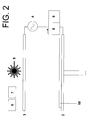
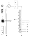
- the apparatus 1 shown in Figure 1 is housed within a process chamber (not shown).
- a negative plasma source electrode 2 and a positive plasma source electrode 3 are connected by a power source 4.
- a laser 5 is positioned above the positive plasma source 3, and is associated with a raster scanning mechanism (not shown).
- a gas supply 6 can be turned on and off to supply a pre-heated process gas to the chamber, such as CH 4 /H 2 .
- a second gas supply 7 can be turned on and off to supply an inert gas such as N 2 to the process chamber.
- the inert gas is preheated to a temperature at or just below the melting point of the matrix material.
- the electrode 2 is also heated by a heating element (not shown) to a similar temperature.
- a heated hopper 8 and a cooled ink-jet printing head 9 are mounted on a transport mechanism (not shown) which can move the hopper 8 and printing head 9 from left to right in Figure 1 (that is, from one end of the negative plasma source 2 to the other).
- a transport mechanism (not shown) is provided for driving the negative plasma source 2 up and down.
- Figures 1-10 are side views of the apparatus, and thus do not show the third (width) dimension out of the plane of the figures. However, the electrodes 2,3, laser 5, hopper 8 and printing head 9 will extend across the width of the apparatus.
- the hopper (8) is filled with a polymer powder such as polyetheretherketone (PEEK).
- PEEK polyetheretherketone
- the hopper 8 is moved across the negative plasma source 2, and a dispensing orifice (not shown) in the hopper 8 is opened to deposit a layer 10 of polymer powder.
- the source 2 also acts as a bed or platform for the additive layer manufacturing process.
- the orifice is then closed.
- the inert gas prevents oxidation of the polymer.
- the laser 5 is turned on and the raster mechanism scans the beam across the layer 10 to consolidate the layer 10. The heating effect of the laser beam causes the polymer layer 10 to melt.
- a shutter (not shown) in the path of the laser beam is opened and closed selectively to modulate the beam as it is scanned over the layer 10.
- the layer 10 is consolidated only in the areas required to form a desired shape. More specifically, the shutter is opened and closed in accordance with a computer-aided design (CAD) model which defines a series of slices through the desired three-dimensional shape.
- CAD computer-aided design
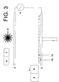
- the printing head 9 is moved across the layer 10 to deposit an array of catalyst particles 11.
- the printing head 9 sprays an array of colloid drops onto the layer 10, and as the colloid evaporates in the high temperature inert gas environment, metal catalyst particles 11 suspended in the colloid drops are deposited.
- the catalyst particles 11 may be, for example a metal, preferably transition metals Fe, Ni or Co, or alloys thereof; and the colloid liquid may be, for example alcohol, water, oil, or a mixture thereof.
- a fluid-based cooling system (not shown) cools the printing head 9 and a reservoir (not shown) containing the printing fluid to prevent the colloid liquid from boiling before it is printed.
- the printing orifice of the printing head 9 (which emits the spray of droplets) is positioned sufficiently close to the layer 10 to ensure that the colloid liquid does not evaporate deleteriously in flight, before hitting the layer 10.
- catalyst particles 11 are shown in Figure 3 for purposes of illustration with a regular spacing along the length of the layer 10, the spacing between the particles will be essentially random in both the length and width dimensions.
- each catalyst particle is typically in the range of 1 nm-1 ⁇ m, and the catalyst particles may be close-packed, or spaced apart.
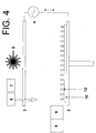
- the carbonaceous feed stock is introduced from the gas supply 6 and the power source 4 is turned on to generate a plasma between the electrodes 2, 3.
- This causes the in-situ growth of a layer of nanofibres 12, aligned with the direction of the electromagnetic field between the electrodes 2,3.
- the growth mechanism is as described by Baker ( Baker, R.T.K., Barber, M.A., Harris, P.S., Feates, F.S. & Waire, R.J. J J Catal 26 (1972 ).
- the catalyst particles and plasma enable the nanofibre growth to occur at a relatively low temperature, lower than the melting point of the matrix.
- the diameter of the nanofibres is typically in the range of 1 nm-1 ⁇ m. Thus, although described as “nanofibres", the diameter of the fibres 12 may exceed 100 nm if desired.
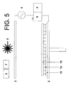
- the plasma power source 4 and gas supply 6 are turned off, the inert gas is purged, and in a fourth process step shown in Figure 5 , the platform 2 is lowered and the hopper 8 is moved along the layer of nanofibres 12 to deposit a further layer 13 of polymer powder.
- the polymer powder size is typically three orders of magnitude larger than the diameter of the nanofibres 12 and significantly greater than the spaces between the nanofibres 12.
- the polymer powder layer 13 sits on top of the layer of nanofibres 12 as shown in Figure 5 .
- the layer 13 has a thickness which is some multiple of the polymer powder size of 20-50 ⁇ m - typically of the order of 0.2-0.5 mm.
- a fifth process step shown in Figure 6 the laser 5 is turned on and the raster mechanism scans the beam across the layer 13 to form a consolidated layer 13'.
- the shutter is opened and closed as required to form the consolidated layer 13' in a desired shape.
- the thickness of the unconsolidated polymer layer 13 is selected so that the layer of nanofibres 12 is only partially impregnated with the matrix through a lower part of its thickness, leaving an upper part of the layer of nanofibres 12 exposed as shown in Figure 6 .
- the thickness of the unconsolidated layer 13 shown in Figure 5 may be in the range of 0.2-0.5 mm
- the thickness of the consolidated layer 13' shown in Figure 6 may be in the range of 0.1-0.25 mm.
- the nanofibres 12, being slightly longer than the layer of consolidated matrix 13' will have lengths exceeding 0.1 mm and aspect ratios exceeding 100.
- the ratio between the length of the fibres 12 and the thickness of the consolidated layer 13' is of the order of 2:1 in Figure 6 , this is for illustrative purposes only and in practice a much smaller degree of overlap (for instance a ratio of 1.05:1) will be required to give significant interlayer reinforcement.
- the laser is then turned off and the five process steps shown in Figures 2-6 are repeated to build up a series of layers of nanofibres; each layer being impregnated with a matrix before depositing the next layer.
- a second layer of catalyst particles 14 is deposited as shown in Figure 7 .
- the catalyst particles 14 are shown in a regular array, interleaved with the array of nanofibres 12. However the distribution of matrix particles 14 will be essentially random in both the length and width dimensions.
- a second layer of nanofibres 15 is then grown, catalysed by the catalyst particles 14. Note that the second layer of nanofibres 15 partially overlaps with the previous layer of nanofibres 12. This results in “interlaminar” reinforcement as well as “intralaminar” reinforcement.
- the second plasma source 3 may be moved relative to the platform 2 so that the nanofibres in the second layer are aligned in a different direction, for instance at an acute angle such as 45° to the vertical.
- the electromagnetic field may be re-oriented for each successive layer of nanofibres if desired.
- a transport mechanism (not shown) is provided to move the plasma source electrode 3 relative to the platform 2 into the position required. Equivalently, a mechanism (not shown) may be provided to move the platform 2, or rotate it, to give the desired angle of electro-magnetic field.
- the negative plasma source 2 is lowered again and a further layer 16 of polymer powder deposited on top of the layer of nanofibres 15.
- the layer 16 is then consolidated by the laser 5 to form a consolidated layer 16'.
- a respective layer of catalyst particles 11,14 is deposited for each layer of fibres.
- the layer of catalyst particles 11 may be re-used to catalyse a succession of layers of fibres which grow end-to-end, instead of growing as a succession of discrete fibres with the overlapping configuration shown in Figure 8 .
- the printing head 9 may be modulated selectively so as to deposit each layer of colloid drops with a desired shape and/or packing density. This enables each layer of nanotubes to be grown with a different shape and/or packing density.
- the packing density of the colloid drops (and hence the packing density of the nanotubes) may also vary across the layer (in the width and/or length direction) as well as varying between layers.
- the layers of matrix powder may be applied by a roller or other feed system which spreads the layer across the substrate.
- a bulk composite material is formed by depositing a series of layers of nanotubes, each layer being impregnated before growth of the next layer.
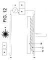
- the same apparatus may be used to form a sheet with only a single layer of nanotubes.
- a layer of nanotubes 17 is grown at an angle to the substrate matrix layer 10 by moving the positive plasma source 3 to the position shown.
- a layer of matrix 18 is then deposited, and consolidated to impregnate the layer of nanotubes 17 as shown in Figure 13 .
- the resulting sheet is then removed from the process chamber, and can be used in the same manner as a conventional "prepreg". That is, a number of such sheets can be laid together to form a laminate structure, cut to shape and moulded to form a composite element.
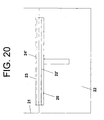
- Figures 14-20 show an additive layer manufacturing system for manufacturing a composite with a thermosetting epoxy resin matrix (instead of the thermoplastic matrix used in the apparatus of Figures 1-13 ).
- the system shown in Figures 14-20 incorporates all of the elements of the system of Figure 1 (except the hopper 8) but these elements are not shown in Figures 14-20 for purposes of clarity.
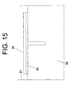
- a platform 20 is immersed in a bath 21 of liquid epoxy resin 22.
- the platform is then lifted up to a position just above the surface of the bath 21 as shown in Figure 15 in which a mound 22 of resin is supported by the platform 20.
- a doctor blade (not shown) wipes across the mound 22 to leave a uniformly thick layer 22' of resin shown in Figure 16 .
- a laser (not shown) is then turned on and scanned across the layer 22' to cause the resin to cure in a desired shape.
- a printing head (not shown) is then moved across the layer 22' to deposit an array of catalyst particles (not shown).
- a carbonaceous feed stock is then introduced into the process chamber, and a plasma from a plasma source (not shown) is applied at an angle to the layer 22 to cause the growth of a layer of nanofibres 23, aligned with the direction of the electromagnetic field.
- An angle of 45° is shown in Figure 17 , although this angle may be as low as 5° if required.
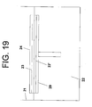
- nanofibres 23 of a suitable length have been grown, the plasma power source and gas supply are turned off, inert gas in the chamber is purged, and the platform 20 is lowered as shown in Figure 18 .
- the platform 20 is then lifted up to the position just above the surface of the bath 21 shown in Figure 19 in which a mound 24 of resin impregnates the layer of nanofibres 23.
- the doctor blade then wipes across the mound 23 to form a uniformly thick layer 24' of resin shown in Figure 20 .
- the laser is then turned on and scanned across the layer 24' to cause the resin to cure in a desired shape.
- the layer 24' is shown in Figure 20 above the layer of nanofibres 23, but in practice the layer 24' may be made sufficiently thin such that after curing it only impregnates the matrix through a lower part of its thickness, in a similar manner to the layer 13' shown in Figure 6 , thus giving partial overlap with the next layer of nanofibres.
- the process is then be repeated further to form a bulk material.
Landscapes
- Chemical & Material Sciences (AREA)
- Engineering & Computer Science (AREA)
- Materials Engineering (AREA)
- Health & Medical Sciences (AREA)
- Composite Materials (AREA)
- Organic Chemistry (AREA)
- Manufacturing & Machinery (AREA)
- Polymers & Plastics (AREA)
- Medicinal Chemistry (AREA)
- Chemical Kinetics & Catalysis (AREA)
- Nanotechnology (AREA)
- Physics & Mathematics (AREA)
- General Chemical & Material Sciences (AREA)
- Crystallography & Structural Chemistry (AREA)
- General Physics & Mathematics (AREA)
- Condensed Matter Physics & Semiconductors (AREA)
- Mechanical Engineering (AREA)
- Inorganic Chemistry (AREA)
- Reinforced Plastic Materials (AREA)
- Catalysts (AREA)
- Chemical Vapour Deposition (AREA)
- Compositions Of Macromolecular Compounds (AREA)
- Physical Vapour Deposition (AREA)
- Inorganic Fibers (AREA)
- Manufacture Of Alloys Or Alloy Compounds (AREA)
- Laminated Bodies (AREA)
- Carbon And Carbon Compounds (AREA)
Priority Applications (1)
| Application Number | Priority Date | Filing Date | Title |
|---|---|---|---|
| EP11185691A EP2409827B1 (en) | 2006-09-05 | 2007-08-29 | Method of manufacturing composite material |
Applications Claiming Priority (3)
| Application Number | Priority Date | Filing Date | Title |
|---|---|---|---|
| US82456506P | 2006-09-05 | 2006-09-05 | |
| GBGB0617460.1A GB0617460D0 (en) | 2006-09-05 | 2006-09-05 | Method of manufacturing composite material |
| PCT/GB2007/050510 WO2008029179A2 (en) | 2006-09-05 | 2007-08-29 | Method of manufacturing composite material by growing of a layer of reinforcement and related apparatus |
Publications (2)
| Publication Number | Publication Date |
|---|---|
| EP2061644A2 EP2061644A2 (en) | 2009-05-27 |
| EP2061644B1 true EP2061644B1 (en) | 2011-10-26 |
Family
ID=37232391
Family Applications (2)
| Application Number | Title | Priority Date | Filing Date |
|---|---|---|---|
| EP07789385A Not-in-force EP2061644B1 (en) | 2006-09-05 | 2007-08-29 | Method of manufacturing composite material by growing of a layer of reinforcement and related apparatus |
| EP11185691A Not-in-force EP2409827B1 (en) | 2006-09-05 | 2007-08-29 | Method of manufacturing composite material |
Family Applications After (1)
| Application Number | Title | Priority Date | Filing Date |
|---|---|---|---|
| EP11185691A Not-in-force EP2409827B1 (en) | 2006-09-05 | 2007-08-29 | Method of manufacturing composite material |
Country Status (10)
| Country | Link |
|---|---|
| US (1) | US20100004388A1 (enExample) |
| EP (2) | EP2061644B1 (enExample) |
| JP (2) | JP5587602B2 (enExample) |
| CN (2) | CN101511570B (enExample) |
| AT (1) | ATE530332T1 (enExample) |
| BR (1) | BRPI0716167A2 (enExample) |
| CA (1) | CA2661746C (enExample) |
| GB (1) | GB0617460D0 (enExample) |
| RU (1) | RU2448832C2 (enExample) |
| WO (1) | WO2008029179A2 (enExample) |
Families Citing this family (9)
| Publication number | Priority date | Publication date | Assignee | Title |
|---|---|---|---|---|
| GB0715164D0 (en) * | 2007-08-06 | 2007-09-12 | Airbus Uk Ltd | Method and apparatus for manufacturing a composite material |
| GB0715990D0 (en) * | 2007-08-16 | 2007-09-26 | Airbus Uk Ltd | Method and apparatus for manufacturing a component from a composite material |
| RU2459888C2 (ru) * | 2010-11-30 | 2012-08-27 | Открытое акционерное общество "Композит" (ОАО "Композит") | Способ получения оболочечных конструкций |
| RU2478562C1 (ru) * | 2011-08-11 | 2013-04-10 | Государственное образовательное учреждение высшего профессионального образования "Владимирский государственный университет имени Александра Григорьевича и Николая Григорьевича Столетовых" (ВлГУ) | Способ получения волокон в электрическом однородном поле |
| RU2567283C2 (ru) * | 2013-11-18 | 2015-11-10 | Александр Григорьевич Григорьянц | Способ и устройство для получения углеродных нанотрубок |
| RU2641921C2 (ru) * | 2016-07-14 | 2018-01-23 | Федеральное государственное бюджетное образовательное учреждение высшего образования "Башкирский государственный университет" | Электропроводящая металлонаполненная полимерная композиция для 3D-печати (варианты) |
| RU2641134C1 (ru) * | 2016-07-14 | 2018-01-16 | Федеральное государственное бюджетное образовательное учреждение высшего образования "Башкирский государственный университет" | Электропроводящая металлонаполненная полимерная композиция для 3D-печати (варианты) |
| WO2018081357A1 (en) * | 2016-10-26 | 2018-05-03 | Purdue Research Foundation | Roll-to-roll manufacturing machines and methods for producing nanostructures-containing polymer films |
| DE102018102061B3 (de) * | 2018-01-30 | 2019-03-14 | Brandenburgische Technische Universität Cottbus-Senftenberg | Extrusionsvorrichtung und Verfahren zur Herstellung vonkohlefaserverstärkten Kunststoffhalbzeugen |
Citations (1)
| Publication number | Priority date | Publication date | Assignee | Title |
|---|---|---|---|---|
| US20040071951A1 (en) * | 2002-09-30 | 2004-04-15 | Sungho Jin | Ultra-high-density information storage media and methods for making the same |
Family Cites Families (38)
| Publication number | Priority date | Publication date | Assignee | Title |
|---|---|---|---|---|
| US4560603A (en) * | 1983-10-27 | 1985-12-24 | Ltv Aerospace And Defense Company | Composite matrix with oriented whiskers |
| RU2048295C1 (ru) * | 1992-01-24 | 1995-11-20 | Юрий Иванович Кадун | Способ изготовления слоистого изделия из композиционного материала |
| US5837081A (en) * | 1993-04-07 | 1998-11-17 | Applied Sciences, Inc. | Method for making a carbon-carbon composite |
| US6156256A (en) * | 1998-05-13 | 2000-12-05 | Applied Sciences, Inc. | Plasma catalysis of carbon nanofibers |
| US6863942B2 (en) * | 1998-06-19 | 2005-03-08 | The Research Foundation Of State University Of New York | Free-standing and aligned carbon nanotubes and synthesis thereof |
| US6265466B1 (en) * | 1999-02-12 | 2001-07-24 | Eikos, Inc. | Electromagnetic shielding composite comprising nanotubes |
| AUPP976499A0 (en) * | 1999-04-16 | 1999-05-06 | Commonwealth Scientific And Industrial Research Organisation | Multilayer carbon nanotube films |
| US6214276B1 (en) * | 1999-05-18 | 2001-04-10 | Creo Srl | Method of forming objects from thermosensitive composition |
| EP1059266A3 (en) * | 1999-06-11 | 2000-12-20 | Iljin Nanotech Co., Ltd. | Mass synthesis method of high purity carbon nanotubes vertically aligned over large-size substrate using thermal chemical vapor deposition |
| WO2001030694A1 (en) * | 1999-10-27 | 2001-05-03 | William Marsh Rice University | Macroscopic ordered assembly of carbon nanotubes |
| US6923946B2 (en) * | 1999-11-26 | 2005-08-02 | Ut-Battelle, Llc | Condensed phase conversion and growth of nanorods instead of from vapor |
| US6495116B1 (en) * | 2000-04-10 | 2002-12-17 | Lockheed Martin Corporation | Net shape manufacturing using carbon nanotubes |
| AU2002236431A1 (en) * | 2000-08-23 | 2002-05-21 | A. Kuper Cynthia | Method for utilizing sol-gel processing in the production of a macroscopic two or three dimensionally ordered array of single wall nanotubes (swnts) |
| US6428890B1 (en) * | 2001-06-07 | 2002-08-06 | National Cheng Kung University | Polymer matrix composite and method for making the same |
| US6921462B2 (en) * | 2001-12-17 | 2005-07-26 | Intel Corporation | Method and apparatus for producing aligned carbon nanotube thermal interface structure |
| US6746768B2 (en) * | 2001-12-26 | 2004-06-08 | Advanced Energy Technology Inc. | Thermal interface material |
| US6913794B2 (en) * | 2002-01-14 | 2005-07-05 | Coherent, Inc. | Diode-laser curing of liquid epoxide encapsulants |
| JP3962862B2 (ja) * | 2002-02-27 | 2007-08-22 | 日立造船株式会社 | カーボンナノチューブを用いた導電性材料およびその製造方法 |
| CN1302064C (zh) * | 2002-04-26 | 2007-02-28 | 住友化学工业株式会社 | 纤维增强聚烯烃树脂组合物和由其制得的模塑制品 |
| FR2844510B1 (fr) * | 2002-09-12 | 2006-06-16 | Snecma Propulsion Solide | Structure fibreuse tridimensionnelle en fibres refractaires, procede pour sa realisation et application aux materiaux composites thermostructuraux |
| US20030154865A1 (en) * | 2002-10-16 | 2003-08-21 | Zornes David A. | Nano coupling magnetoadsorbent |
| US6841003B2 (en) * | 2002-11-22 | 2005-01-11 | Cdream Display Corporation | Method for forming carbon nanotubes with intermediate purification steps |
| JP2004298357A (ja) * | 2003-03-31 | 2004-10-28 | Mizuno Technics Kk | ゴルフシャフト |
| US7118941B2 (en) * | 2003-06-25 | 2006-10-10 | Intel Corporation | Method of fabricating a composite carbon nanotube thermal interface device |
| JP2005041835A (ja) * | 2003-07-24 | 2005-02-17 | Fuji Xerox Co Ltd | カーボンナノチューブ構造体、その製造方法、カーボンナノチューブ転写体および溶液 |
| CN1863954B (zh) * | 2003-08-04 | 2013-07-31 | 纳米系统公司 | 制备纳米线复合体的系统和方法及由此得到的电子衬底 |
| US20050116336A1 (en) * | 2003-09-16 | 2005-06-02 | Koila, Inc. | Nano-composite materials for thermal management applications |
| US20050061496A1 (en) * | 2003-09-24 | 2005-03-24 | Matabayas James Christopher | Thermal interface material with aligned carbon nanotubes |
| US7181836B2 (en) * | 2003-12-19 | 2007-02-27 | General Electric Company | Method for making an electrode structure |
| US20050169831A1 (en) * | 2004-02-04 | 2005-08-04 | Montgomery Stephen W. | Three-dimensional nanotube structure |
| CN100383213C (zh) * | 2004-04-02 | 2008-04-23 | 清华大学 | 一种热界面材料及其制造方法 |
| JP4512750B2 (ja) * | 2004-04-19 | 2010-07-28 | 独立行政法人科学技術振興機構 | 炭素系微細構造物群、炭素系微細構造物の集合体、その利用およびその製造方法 |
| US20050279274A1 (en) * | 2004-04-30 | 2005-12-22 | Chunming Niu | Systems and methods for nanowire growth and manufacturing |
| US20060025515A1 (en) * | 2004-07-27 | 2006-02-02 | Mainstream Engineering Corp. | Nanotube composites and methods for producing |
| US7129097B2 (en) * | 2004-07-29 | 2006-10-31 | International Business Machines Corporation | Integrated circuit chip utilizing oriented carbon nanotube conductive layers |
| JP2006069165A (ja) * | 2004-09-06 | 2006-03-16 | Japan Science & Technology Agency | カーボンナノチューブ複合シート、およびその製造方法 |
| US20060083927A1 (en) * | 2004-10-15 | 2006-04-20 | Zyvex Corporation | Thermal interface incorporating nanotubes |
| AU2006312250B2 (en) * | 2005-06-28 | 2011-07-07 | The Board Of Regents Of The University Of Oklahoma | Methods for growing and harvesting carbon nanotubes |
-
2006
- 2006-09-05 GB GBGB0617460.1A patent/GB0617460D0/en not_active Ceased
-
2007
- 2007-08-29 US US12/439,267 patent/US20100004388A1/en not_active Abandoned
- 2007-08-29 JP JP2009527212A patent/JP5587602B2/ja not_active Expired - Fee Related
- 2007-08-29 WO PCT/GB2007/050510 patent/WO2008029179A2/en not_active Ceased
- 2007-08-29 CN CN200780032906XA patent/CN101511570B/zh not_active Expired - Fee Related
- 2007-08-29 EP EP07789385A patent/EP2061644B1/en not_active Not-in-force
- 2007-08-29 AT AT07789385T patent/ATE530332T1/de not_active IP Right Cessation
- 2007-08-29 CA CA2661746A patent/CA2661746C/en not_active Expired - Fee Related
- 2007-08-29 CN CN2012102875795A patent/CN102774016A/zh active Pending
- 2007-08-29 RU RU2009110970/05A patent/RU2448832C2/ru not_active IP Right Cessation
- 2007-08-29 BR BRPI0716167-0A2A patent/BRPI0716167A2/pt not_active IP Right Cessation
- 2007-08-29 EP EP11185691A patent/EP2409827B1/en not_active Not-in-force
-
2013
- 2013-03-28 JP JP2013068680A patent/JP5588038B2/ja not_active Expired - Fee Related
Patent Citations (1)
| Publication number | Priority date | Publication date | Assignee | Title |
|---|---|---|---|---|
| US20040071951A1 (en) * | 2002-09-30 | 2004-04-15 | Sungho Jin | Ultra-high-density information storage media and methods for making the same |
Also Published As
| Publication number | Publication date |
|---|---|
| GB0617460D0 (en) | 2006-10-18 |
| EP2409827A1 (en) | 2012-01-25 |
| WO2008029179A3 (en) | 2008-04-24 |
| CN101511570A (zh) | 2009-08-19 |
| CN102774016A (zh) | 2012-11-14 |
| JP2013144809A (ja) | 2013-07-25 |
| CA2661746A1 (en) | 2008-03-13 |
| EP2409827B1 (en) | 2012-11-28 |
| JP2010502808A (ja) | 2010-01-28 |
| JP5587602B2 (ja) | 2014-09-10 |
| CA2661746C (en) | 2015-03-31 |
| ATE530332T1 (de) | 2011-11-15 |
| BRPI0716167A2 (pt) | 2013-09-17 |
| WO2008029179A2 (en) | 2008-03-13 |
| US20100004388A1 (en) | 2010-01-07 |
| EP2061644A2 (en) | 2009-05-27 |
| RU2448832C2 (ru) | 2012-04-27 |
| CN101511570B (zh) | 2012-10-03 |
| JP5588038B2 (ja) | 2014-09-10 |
| RU2009110970A (ru) | 2010-10-20 |
Similar Documents
| Publication | Publication Date | Title |
|---|---|---|
| EP2061643B1 (en) | Method of manufacturing composite material by growing of layers of reinforcement | |
| EP2061644B1 (en) | Method of manufacturing composite material by growing of a layer of reinforcement and related apparatus | |
| CA2695847C (en) | Method and apparatus for manufacturing a composite material | |
| RU2447994C2 (ru) | Способ получения композиционного материала путем выращивания слоев армирования и соответствующее устройство | |
| EP3664985B1 (en) | System and process for manufacturing aligned discontinuous fiber composites | |
| US20120280430A1 (en) | Composite tooling containing carbon nanotubes and production of parts therefrom | |
| Srivastava et al. | Smart manufacturing process of carbon-based low-dimensional structures and fiber-reinforced polymer composites for engineering applications | |
| CN114654845B (zh) | 具有增强的导热性的聚合物夹层结构体及其制造方法 | |
| US20140057084A1 (en) | Composite material |
Legal Events
| Date | Code | Title | Description |
|---|---|---|---|
| PUAI | Public reference made under article 153(3) epc to a published international application that has entered the european phase |
Free format text: ORIGINAL CODE: 0009012 |
|
| 17P | Request for examination filed |
Effective date: 20090217 |
|
| AK | Designated contracting states |
Kind code of ref document: A2 Designated state(s): AT BE BG CH CY CZ DE DK EE ES FI FR GB GR HU IE IS IT LI LT LU LV MC MT NL PL PT RO SE SI SK TR |
|
| AX | Request for extension of the european patent |
Extension state: AL BA HR MK RS |
|
| DAX | Request for extension of the european patent (deleted) | ||
| 17Q | First examination report despatched |
Effective date: 20091119 |
|
| RAP1 | Party data changed (applicant data changed or rights of an application transferred) |
Owner name: AIRBUS OPERATIONS LIMITED |
|
| GRAP | Despatch of communication of intention to grant a patent |
Free format text: ORIGINAL CODE: EPIDOSNIGR1 |
|
| GRAS | Grant fee paid |
Free format text: ORIGINAL CODE: EPIDOSNIGR3 |
|
| GRAA | (expected) grant |
Free format text: ORIGINAL CODE: 0009210 |
|
| AK | Designated contracting states |
Kind code of ref document: B1 Designated state(s): AT BE BG CH CY CZ DE DK EE ES FI FR GB GR HU IE IS IT LI LT LU LV MC MT NL PL PT RO SE SI SK TR |
|
| REG | Reference to a national code |
Ref country code: GB Ref legal event code: FG4D |
|
| REG | Reference to a national code |
Ref country code: CH Ref legal event code: EP |
|
| REG | Reference to a national code |
Ref country code: IE Ref legal event code: FG4D |
|
| REG | Reference to a national code |
Ref country code: DE Ref legal event code: R096 Ref document number: 602007018278 Country of ref document: DE Effective date: 20120105 |
|
| REG | Reference to a national code |
Ref country code: NL Ref legal event code: VDEP Effective date: 20111026 |
|
| LTIE | Lt: invalidation of european patent or patent extension |
Effective date: 20111026 |
|
| REG | Reference to a national code |
Ref country code: AT Ref legal event code: MK05 Ref document number: 530332 Country of ref document: AT Kind code of ref document: T Effective date: 20111026 |
|
| PG25 | Lapsed in a contracting state [announced via postgrant information from national office to epo] |
Ref country code: BE Free format text: LAPSE BECAUSE OF FAILURE TO SUBMIT A TRANSLATION OF THE DESCRIPTION OR TO PAY THE FEE WITHIN THE PRESCRIBED TIME-LIMIT Effective date: 20111026 Ref country code: LT Free format text: LAPSE BECAUSE OF FAILURE TO SUBMIT A TRANSLATION OF THE DESCRIPTION OR TO PAY THE FEE WITHIN THE PRESCRIBED TIME-LIMIT Effective date: 20111026 Ref country code: IS Free format text: LAPSE BECAUSE OF FAILURE TO SUBMIT A TRANSLATION OF THE DESCRIPTION OR TO PAY THE FEE WITHIN THE PRESCRIBED TIME-LIMIT Effective date: 20120226 |
|
| PG25 | Lapsed in a contracting state [announced via postgrant information from national office to epo] |
Ref country code: SE Free format text: LAPSE BECAUSE OF FAILURE TO SUBMIT A TRANSLATION OF THE DESCRIPTION OR TO PAY THE FEE WITHIN THE PRESCRIBED TIME-LIMIT Effective date: 20111026 Ref country code: SI Free format text: LAPSE BECAUSE OF FAILURE TO SUBMIT A TRANSLATION OF THE DESCRIPTION OR TO PAY THE FEE WITHIN THE PRESCRIBED TIME-LIMIT Effective date: 20111026 Ref country code: NL Free format text: LAPSE BECAUSE OF FAILURE TO SUBMIT A TRANSLATION OF THE DESCRIPTION OR TO PAY THE FEE WITHIN THE PRESCRIBED TIME-LIMIT Effective date: 20111026 Ref country code: GR Free format text: LAPSE BECAUSE OF FAILURE TO SUBMIT A TRANSLATION OF THE DESCRIPTION OR TO PAY THE FEE WITHIN THE PRESCRIBED TIME-LIMIT Effective date: 20120127 Ref country code: PL Free format text: LAPSE BECAUSE OF FAILURE TO SUBMIT A TRANSLATION OF THE DESCRIPTION OR TO PAY THE FEE WITHIN THE PRESCRIBED TIME-LIMIT Effective date: 20111026 Ref country code: PT Free format text: LAPSE BECAUSE OF FAILURE TO SUBMIT A TRANSLATION OF THE DESCRIPTION OR TO PAY THE FEE WITHIN THE PRESCRIBED TIME-LIMIT Effective date: 20120227 Ref country code: LV Free format text: LAPSE BECAUSE OF FAILURE TO SUBMIT A TRANSLATION OF THE DESCRIPTION OR TO PAY THE FEE WITHIN THE PRESCRIBED TIME-LIMIT Effective date: 20111026 |
|
| PG25 | Lapsed in a contracting state [announced via postgrant information from national office to epo] |
Ref country code: CY Free format text: LAPSE BECAUSE OF FAILURE TO SUBMIT A TRANSLATION OF THE DESCRIPTION OR TO PAY THE FEE WITHIN THE PRESCRIBED TIME-LIMIT Effective date: 20111026 |
|
| PG25 | Lapsed in a contracting state [announced via postgrant information from national office to epo] |
Ref country code: EE Free format text: LAPSE BECAUSE OF FAILURE TO SUBMIT A TRANSLATION OF THE DESCRIPTION OR TO PAY THE FEE WITHIN THE PRESCRIBED TIME-LIMIT Effective date: 20111026 Ref country code: CZ Free format text: LAPSE BECAUSE OF FAILURE TO SUBMIT A TRANSLATION OF THE DESCRIPTION OR TO PAY THE FEE WITHIN THE PRESCRIBED TIME-LIMIT Effective date: 20111026 Ref country code: BG Free format text: LAPSE BECAUSE OF FAILURE TO SUBMIT A TRANSLATION OF THE DESCRIPTION OR TO PAY THE FEE WITHIN THE PRESCRIBED TIME-LIMIT Effective date: 20120126 Ref country code: DK Free format text: LAPSE BECAUSE OF FAILURE TO SUBMIT A TRANSLATION OF THE DESCRIPTION OR TO PAY THE FEE WITHIN THE PRESCRIBED TIME-LIMIT Effective date: 20111026 Ref country code: SK Free format text: LAPSE BECAUSE OF FAILURE TO SUBMIT A TRANSLATION OF THE DESCRIPTION OR TO PAY THE FEE WITHIN THE PRESCRIBED TIME-LIMIT Effective date: 20111026 |
|
| PG25 | Lapsed in a contracting state [announced via postgrant information from national office to epo] |
Ref country code: RO Free format text: LAPSE BECAUSE OF FAILURE TO SUBMIT A TRANSLATION OF THE DESCRIPTION OR TO PAY THE FEE WITHIN THE PRESCRIBED TIME-LIMIT Effective date: 20111026 |
|
| PLBE | No opposition filed within time limit |
Free format text: ORIGINAL CODE: 0009261 |
|
| STAA | Information on the status of an ep patent application or granted ep patent |
Free format text: STATUS: NO OPPOSITION FILED WITHIN TIME LIMIT |
|
| 26N | No opposition filed |
Effective date: 20120727 |
|
| REG | Reference to a national code |
Ref country code: DE Ref legal event code: R097 Ref document number: 602007018278 Country of ref document: DE Effective date: 20120727 |
|
| PG25 | Lapsed in a contracting state [announced via postgrant information from national office to epo] |
Ref country code: AT Free format text: LAPSE BECAUSE OF FAILURE TO SUBMIT A TRANSLATION OF THE DESCRIPTION OR TO PAY THE FEE WITHIN THE PRESCRIBED TIME-LIMIT Effective date: 20111026 |
|
| REG | Reference to a national code |
Ref country code: CH Ref legal event code: PL |
|
| PG25 | Lapsed in a contracting state [announced via postgrant information from national office to epo] |
Ref country code: MC Free format text: LAPSE BECAUSE OF NON-PAYMENT OF DUE FEES Effective date: 20120831 |
|
| PG25 | Lapsed in a contracting state [announced via postgrant information from national office to epo] |
Ref country code: ES Free format text: LAPSE BECAUSE OF FAILURE TO SUBMIT A TRANSLATION OF THE DESCRIPTION OR TO PAY THE FEE WITHIN THE PRESCRIBED TIME-LIMIT Effective date: 20120206 Ref country code: CH Free format text: LAPSE BECAUSE OF NON-PAYMENT OF DUE FEES Effective date: 20120831 Ref country code: LI Free format text: LAPSE BECAUSE OF NON-PAYMENT OF DUE FEES Effective date: 20120831 |
|
| REG | Reference to a national code |
Ref country code: IE Ref legal event code: MM4A |
|
| PG25 | Lapsed in a contracting state [announced via postgrant information from national office to epo] |
Ref country code: FI Free format text: LAPSE BECAUSE OF FAILURE TO SUBMIT A TRANSLATION OF THE DESCRIPTION OR TO PAY THE FEE WITHIN THE PRESCRIBED TIME-LIMIT Effective date: 20111026 |
|
| PG25 | Lapsed in a contracting state [announced via postgrant information from national office to epo] |
Ref country code: IE Free format text: LAPSE BECAUSE OF NON-PAYMENT OF DUE FEES Effective date: 20120829 |
|
| PG25 | Lapsed in a contracting state [announced via postgrant information from national office to epo] |
Ref country code: MT Free format text: LAPSE BECAUSE OF FAILURE TO SUBMIT A TRANSLATION OF THE DESCRIPTION OR TO PAY THE FEE WITHIN THE PRESCRIBED TIME-LIMIT Effective date: 20111026 |
|
| PG25 | Lapsed in a contracting state [announced via postgrant information from national office to epo] |
Ref country code: TR Free format text: LAPSE BECAUSE OF FAILURE TO SUBMIT A TRANSLATION OF THE DESCRIPTION OR TO PAY THE FEE WITHIN THE PRESCRIBED TIME-LIMIT Effective date: 20111026 |
|
| REG | Reference to a national code |
Ref country code: DE Ref legal event code: R082 Ref document number: 602007018278 Country of ref document: DE Representative=s name: TETZNER & PARTNER MBB PATENT- UND RECHTSANWAEL, DE |
|
| PG25 | Lapsed in a contracting state [announced via postgrant information from national office to epo] |
Ref country code: LU Free format text: LAPSE BECAUSE OF NON-PAYMENT OF DUE FEES Effective date: 20120829 |
|
| PG25 | Lapsed in a contracting state [announced via postgrant information from national office to epo] |
Ref country code: HU Free format text: LAPSE BECAUSE OF FAILURE TO SUBMIT A TRANSLATION OF THE DESCRIPTION OR TO PAY THE FEE WITHIN THE PRESCRIBED TIME-LIMIT Effective date: 20070829 |
|
| REG | Reference to a national code |
Ref country code: FR Ref legal event code: PLFP Year of fee payment: 9 |
|
| PGFP | Annual fee paid to national office [announced via postgrant information from national office to epo] |
Ref country code: IT Payment date: 20150821 Year of fee payment: 9 |
|
| REG | Reference to a national code |
Ref country code: FR Ref legal event code: PLFP Year of fee payment: 10 |
|
| REG | Reference to a national code |
Ref country code: FR Ref legal event code: PLFP Year of fee payment: 11 |
|
| PG25 | Lapsed in a contracting state [announced via postgrant information from national office to epo] |
Ref country code: IT Free format text: LAPSE BECAUSE OF NON-PAYMENT OF DUE FEES Effective date: 20160829 |
|
| PGFP | Annual fee paid to national office [announced via postgrant information from national office to epo] |
Ref country code: DE Payment date: 20170822 Year of fee payment: 11 Ref country code: GB Payment date: 20170822 Year of fee payment: 11 Ref country code: FR Payment date: 20170822 Year of fee payment: 11 |
|
| REG | Reference to a national code |
Ref country code: DE Ref legal event code: R119 Ref document number: 602007018278 Country of ref document: DE |
|
| GBPC | Gb: european patent ceased through non-payment of renewal fee |
Effective date: 20180829 |
|
| PG25 | Lapsed in a contracting state [announced via postgrant information from national office to epo] |
Ref country code: DE Free format text: LAPSE BECAUSE OF NON-PAYMENT OF DUE FEES Effective date: 20190301 |
|
| PG25 | Lapsed in a contracting state [announced via postgrant information from national office to epo] |
Ref country code: FR Free format text: LAPSE BECAUSE OF NON-PAYMENT OF DUE FEES Effective date: 20180831 |
|
| PG25 | Lapsed in a contracting state [announced via postgrant information from national office to epo] |
Ref country code: GB Free format text: LAPSE BECAUSE OF NON-PAYMENT OF DUE FEES Effective date: 20180829 |