EP2409827B1 - Method of manufacturing composite material - Google Patents
Method of manufacturing composite material Download PDFInfo
- Publication number
- EP2409827B1 EP2409827B1 EP11185691A EP11185691A EP2409827B1 EP 2409827 B1 EP2409827 B1 EP 2409827B1 EP 11185691 A EP11185691 A EP 11185691A EP 11185691 A EP11185691 A EP 11185691A EP 2409827 B1 EP2409827 B1 EP 2409827B1
- Authority
- EP
- European Patent Office
- Prior art keywords
- layer
- reinforcement
- matrix
- catalyst particles
- composite material
- Prior art date
- Legal status (The legal status is an assumption and is not a legal conclusion. Google has not performed a legal analysis and makes no representation as to the accuracy of the status listed.)
- Not-in-force
Links
Images


Classifications
-
- C—CHEMISTRY; METALLURGY
- C08—ORGANIC MACROMOLECULAR COMPOUNDS; THEIR PREPARATION OR CHEMICAL WORKING-UP; COMPOSITIONS BASED THEREON
- C08J—WORKING-UP; GENERAL PROCESSES OF COMPOUNDING; AFTER-TREATMENT NOT COVERED BY SUBCLASSES C08B, C08C, C08F, C08G or C08H
- C08J7/00—Chemical treatment or coating of shaped articles made of macromolecular substances
- C08J7/12—Chemical modification
- C08J7/123—Treatment by wave energy or particle radiation
-
- B—PERFORMING OPERATIONS; TRANSPORTING
- B29—WORKING OF PLASTICS; WORKING OF SUBSTANCES IN A PLASTIC STATE IN GENERAL
- B29C—SHAPING OR JOINING OF PLASTICS; SHAPING OF MATERIAL IN A PLASTIC STATE, NOT OTHERWISE PROVIDED FOR; AFTER-TREATMENT OF THE SHAPED PRODUCTS, e.g. REPAIRING
- B29C70/00—Shaping composites, i.e. plastics material comprising reinforcements, fillers or preformed parts, e.g. inserts
- B29C70/04—Shaping composites, i.e. plastics material comprising reinforcements, fillers or preformed parts, e.g. inserts comprising reinforcements only, e.g. self-reinforcing plastics
- B29C70/28—Shaping operations therefor
- B29C70/30—Shaping by lay-up, i.e. applying fibres, tape or broadsheet on a mould, former or core; Shaping by spray-up, i.e. spraying of fibres on a mould, former or core
-
- B—PERFORMING OPERATIONS; TRANSPORTING
- B33—ADDITIVE MANUFACTURING TECHNOLOGY
- B33Y—ADDITIVE MANUFACTURING, i.e. MANUFACTURING OF THREE-DIMENSIONAL [3-D] OBJECTS BY ADDITIVE DEPOSITION, ADDITIVE AGGLOMERATION OR ADDITIVE LAYERING, e.g. BY 3-D PRINTING, STEREOLITHOGRAPHY OR SELECTIVE LASER SINTERING
- B33Y10/00—Processes of additive manufacturing
-
- B—PERFORMING OPERATIONS; TRANSPORTING
- B82—NANOTECHNOLOGY
- B82Y—SPECIFIC USES OR APPLICATIONS OF NANOSTRUCTURES; MEASUREMENT OR ANALYSIS OF NANOSTRUCTURES; MANUFACTURE OR TREATMENT OF NANOSTRUCTURES
- B82Y30/00—Nanotechnology for materials or surface science, e.g. nanocomposites
-
- C—CHEMISTRY; METALLURGY
- C08—ORGANIC MACROMOLECULAR COMPOUNDS; THEIR PREPARATION OR CHEMICAL WORKING-UP; COMPOSITIONS BASED THEREON
- C08J—WORKING-UP; GENERAL PROCESSES OF COMPOUNDING; AFTER-TREATMENT NOT COVERED BY SUBCLASSES C08B, C08C, C08F, C08G or C08H
- C08J5/00—Manufacture of articles or shaped materials containing macromolecular substances
- C08J5/04—Reinforcing macromolecular compounds with loose or coherent fibrous material
- C08J5/0405—Reinforcing macromolecular compounds with loose or coherent fibrous material with inorganic fibres
- C08J5/042—Reinforcing macromolecular compounds with loose or coherent fibrous material with inorganic fibres with carbon fibres
-
- B—PERFORMING OPERATIONS; TRANSPORTING
- B29—WORKING OF PLASTICS; WORKING OF SUBSTANCES IN A PLASTIC STATE IN GENERAL
- B29C—SHAPING OR JOINING OF PLASTICS; SHAPING OF MATERIAL IN A PLASTIC STATE, NOT OTHERWISE PROVIDED FOR; AFTER-TREATMENT OF THE SHAPED PRODUCTS, e.g. REPAIRING
- B29C70/00—Shaping composites, i.e. plastics material comprising reinforcements, fillers or preformed parts, e.g. inserts
- B29C70/58—Shaping composites, i.e. plastics material comprising reinforcements, fillers or preformed parts, e.g. inserts comprising fillers only, e.g. particles, powder, beads, flakes, spheres
- B29C70/62—Shaping composites, i.e. plastics material comprising reinforcements, fillers or preformed parts, e.g. inserts comprising fillers only, e.g. particles, powder, beads, flakes, spheres the filler being oriented during moulding
Definitions
- the present invention relates to a method of manufacturing a composite material.
- Nanocomposites based on carbon nanotubes are described in E. T. Thostenson and T-W. Chou, "Aligned Multi-Walled Carbon Nanotube-Reinforced Composites: Processing and Mechanical Characterization," Journal of Physics D: Applied Physics, 35(16) L77-L80 (2002 ). According to this paper, one of the most significant challenges towards improving the properties of the nanocomposite is to obtain a uniform dispersion of nanotubes within the polymer matrix. The solution presented in this paper is a micro-scale twin-screw extruder.
- thermal interface material which includes a macromolecular material with a plurality of carbon nanotubes embedded uniformly therein.
- a first aspect of the invention provides a method of manufacturing a composite material, the method comprising:
- the invention may be used to form sheets (either single layer or multi-layer) which are processed in a similar manner to a conventional "prepreg", that is by laying the sheets together to form a laminate structure; and moulding the laminate structure to form a composite element.
- Each layer of reinforcement may be manufactured by forming a layer of catalyst particles to catalyse the growth of the reinforcement layers by spraying droplets of liquid onto a surface, the liquid containing the catalyst particles in suspension or solution.
- the method may include growing each layer of reinforcement with a packing density which varies across the layer
- the layer of reinforcement may be grown in-situ by an arc discharge process, in which stock material contained in a negative electrode sublimates because of the high temperatures caused by the discharge.
- the layer of reinforcement may be grown in-situ by a laser ablation process, in which a pulsed laser vaporizes a target in a high temperature reactor while an inert gas is bled into a process chamber.
- the reinforcement layer develops on the cooler surfaces of the reactor, as the vaporized material condenses.
- the elements (such as carbon nanotubes) making up the reinforcement layer are formed in a gaseous state, and in-situ growth of the layer occurs by condensation of the elements on a substrate.
- the method further comprises forming a layer of catalyst particles to catalyse the growth of the reinforcement, for instance as part of a chemical vapour deposition process.
- This enables growth to be carried out at lower temperatures, typically in the range of 25-500°C.
- the layer grows by in-situ growth of the elements making up the reinforcement layer, instead of growing by accumulation of pre-formed elements.
- the catalyst particles may be deposited directly, through the precipitation of metal salts held in solution in water, oil or alcohol, or they may be deposited as a colloid suspension, for instance from a printing head.
- the method further comprises heating the matrix during impregnation, using a laser or other heat source.
- the matrix material is typically deposited as a layer, for instance a powder layer which is heated in-situ to impregnate the reinforcement.
- Impregnation typically occurs by a process of capillary action.
- the matrix may be a metal such as Titanium, or a polymer such as a thermosetting resin or a thermoplastic material such as polyetheretherketone (PEEK).
- a metal such as Titanium
- a polymer such as a thermosetting resin or a thermoplastic material such as polyetheretherketone (PEEK).
- the reinforcement layer typically comprises reinforcement elements having an elongate structure such as tubes, fibres or plates.
- the reinforcement elements may be solid or tubular.
- the reinforcement elements may be single walled carbon nanotubes; multi-walled carbon nanotubes; or carbon nanotubes coated with a layer of amorphous carbon.
- the reinforcement layer comprises reinforcement elements having an aspect ratio greater than 100.
- the reinforcement layer comprises reinforcement elements having a diameter less than 100 nm.
- the reinforcement may be formed of any material such as silicon carbide or alumina, but preferably the reinforcement layer comprises carbon fibres. This is preferred due to the strength and stiffness of the carbon-carbon bond.
- the apparatus 1 shown in Figure 1 (which is suitable for use with manufacturing methods according to the present invention) is housed within a process chamber (not shown).
- a negative plasma source electrode 2 and a positive plasma source electrode 3 are connected by a power source 4.
- a laser 5 is positioned above the positive plasma source 3, and is associated with a raster scanning mechanism (not shown).
- a gas supply 6 can be turned on and off to supply a pre-heated process gas to the chamber, such as CH 4 /H 2 .
- a second gas supply 7 can be turned on and off to supply an inert gas such as N 2 to the process chamber.
- the inert gas is preheated to a temperature at or just below the melting point of the matrix material.
- the electrode 2 is also heated by a heating element (not shown) to a similar temperature.
- a heated hopper 8 and a cooled ink-jet printing head 9 are mounted on a transport mechanism (not shown) which can move the hopper 8 and printing head 9 from left to right in Figure 1 (that is, from one end of the negative plasma source 2 to the other).
- a transport mechanism (not shown) is provided for driving the negative plasma source 2 up and down.
- Figures 1-10 are side views of the apparatus, and thus do not show the third (width) dimension out of the plane of the figures. However, the electrodes 2,3, laser 5, hopper 8 and printing head 9 will extend across the width of the apparatus.
- the hopper (8) is filled with a polymer powder such as polyetheretherketone (PEEK).
- PEEK polyetheretherketone
- the hopper 8 is moved across the negative plasma source 2, and a dispensing orifice (not shown) in the hopper 8 is opened to deposit a layer 10 of polymer powder.
- the source 2 also acts as a bed or platform for the additive layer manufacturing process.
- the orifice is then closed.
- the inert gas prevents oxidation of the polymer.
- the laser 5 is turned on and the raster mechanism scans the beam across the layer 10 to consolidate the layer 10. The heating effect of the laser beam causes the polymer layer 10 to melt.
- a shutter (not shown) in the path of the laser beam is opened and closed selectively to modulate the beam as it is scanned over the layer 10.
- the layer 10 is consolidated only in the areas required to form a desired shape. More specifically, the shutter is opened and closed in accordance with a computer-aided design (CAD) model which defines a series of slices through the desired three-dimensional shape.
- CAD computer-aided design
- the printing head 9 is moved across the layer 10 to deposit an array of catalyst particles 11.
- the printing head 9 sprays an array of colloid drops onto the layer 10, and as the colloid evaporates in the high temperature inert gas environment, metal catalyst particles 11 suspended in the colloid drops are deposited.
- the catalyst particles 11 may be, for example a metal, preferably transition metals Fe, Ni or Co, or alloys thereof; and the colloid liquid may be, for example alcohol, water, oil, or a mixture thereof.
- a fluid-based cooling system (not shown) cools the printing head 9 and a reservoir (not shown) containing the printing fluid to prevent the colloid liquid from boiling before it is printed.
- the printing orifice of the printing head 9 (which emits the spray of droplets) is positioned sufficiently close to the layer 10 to ensure that the colloid liquid does not evaporate deleteriously in flight, before hitting the layer 10.
- catalyst particles 11 are shown in Figure 3 for purposes of illustration with a regular spacing along the length of the layer 10, the spacing between the particles will be essentially random in both the length and width dimensions.
- each catalyst particle is typically in the range of 1 nm-1 ⁇ m, and the catalyst particles may be close-packed, or spaced apart.
- the carbonaceous feed stock is introduced from the gas supply 6 and the power source 4 is turned on to generate a plasma between the electrodes 2, 3.
- This causes the in-situ growth of a layer of nanofibres 12, aligned with the direction of the electromagnetic field between the electrodes 2,3.
- the growth mechanism is as described by Baker ( Baker, R.T.K., Barber, M.A., Harris, P.S., Feates, F.S. & Waire, R.J. J J Catal 26 (1972 ).
- the catalyst particles and plasma enable the nanofibre growth to occur at a relatively low temperature, lower than the melting point of the matrix.
- the diameter of the nanofibres is typically in the range of 1 nm-1 ⁇ m. Thus, although described as “nanofibres", the diameter of the fibres 12 may exceed 100 nm if desired.
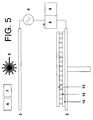
- the plasma power source 4 and gas supply 6 are turned off, the inert gas is purged, and in a fourth process step shown in Figure 5 , the platform 2 is lowered and the hopper 8 is moved along the layer of nanofibres 12 to deposit a further layer 13 of polymer powder.
- the polymer powder size is typically three orders of magnitude larger than the diameter of the nanofibres 12 and significantly greater than the spaces between the nanofibres 12.
- the polymer powder layer 13 sits on top of the layer of nanofibres 12 as shown in Figure 5 .
- the layer 13 has a thickness which is some multiple of the polymer powder size of 20-50 ⁇ m - typically of the order of 0.2-0.5 mm.
- a fifth process step shown in Figure 6 the laser 5 is turned on and the raster mechanism scans the beam across the layer 13 to form a consolidated layer 13'.
- the shutter is opened and closed as required to form the consolidated layer 13' in a desired shape.
- the thickness of the unconsolidated polymer layer 13 is selected so that the layer of nanofibres 12 is only partially impregnated with the matrix through a lower part of its thickness, leaving an upper part of the layer of nanofibres 12 exposed as shown in Figure 6 .
- the thickness of the unconsolidated layer 13 shown in Figure 5 may be in the range of 0.2-0.5 mm
- the thickness of the consolidated layer 13' shown in Figure 6 may be in the range of 0.1-0.25 mm.
- the nanofibres 12, being slightly longer than the layer of consolidated matrix 13' will have lengths exceeding 0.1 mm and aspect ratios exceeding 100.
- the ratio between the length of the fibres 12 and the thickness of the consolidated layer 13' is of the order of 2:1 in Figure 6 , this is for illustrative purposes only and in practice a much smaller degree of overlap (for instance a ratio of 1.05:1) will be required to give significant interlayer reinforcement.
- the laser is then turned off and the five process steps shown in Figures 2-6 are repeated to build up a series of layers of nanofibres; each layer being impregnated with a matrix before depositing the next layer.
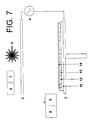
- a second layer of catalyst particles 14 is deposited as shown in Figure 7 .
- the catalyst particles 14 are shown in a regular array, interleaved with the array of nanofibres 12. However the distribution of matrix particles 14 will be essentially random in both the length and width dimensions.
- a second layer of nanofibres 15 is then grown, catalysed by the catalyst particles 14. Note that the second layer of nanofibres 15 partially overlaps with the previous layer of nanofibres 12. This results in “interlaminar” reinforcement as well as “intralaminar” reinforcement.
- the second plasma source 3 may be moved relative to the platform 2 so that the nanofibres in the second layer are aligned in a different direction, for instance at an acute angle such as 45° to the vertical.
- the electromagnetic field may be re-oriented for each successive layer of nanofibres if desired.
- a transport mechanism (not shown) is provided to move the plasma source electrode 3 relative to the platform 2 into the position required. Equivalently, a mechanism (not shown) may be provided to move the platform 2, or rotate it, to give the desired angle of electro-magnetic field.
- the negative plasma source 2 is lowered again and a further layer 16 of polymer powder deposited on top of the layer of nanofibres 15.
- the layer 16 is then consolidated by the laser 5 to form a consolidated layer 16'.
- a respective layer of catalyst particles 11,14 is deposited for each layer of fibres.
- the layer of catalyst particles 11 may be re-used to catalyse a succession of layers of fibres which grow end-to-end, instead of growing as a succession of discrete fibres with the overlapping configuration shown in Figure 8 .
- the printing head 9 may be modulated selectively so as to deposit each layer of colloid drops with a desired shape and/or packing density. This enables each layer of nanotubes to be grown with a different shape and/or packing density.
- the packing density of the colloid drops (and hence the packing density of the nanotubes) may also vary across the layer (in the width and/or length direction) as well as varying between layers.
- the layers of matrix powder may be applied by a roller or other feed system which spreads the layer across the substrate.
- a bulk composite material is formed by depositing a series of layers of nanotubes, each layer being impregnated before growth of the next layer.
- the same apparatus may be used to form a sheet with only a single layer of nanotubes.
- a layer of nanotubes 17 is grown at an angle to the substrate matrix layer 10 by moving the positive plasma source 3 to the position shown.
- a layer of matrix 18 is then deposited, and consolidated to impregnate the layer of nanotubes 17 as shown in Figure 13 .
- the resulting sheet is then removed from the process chamber, and can be used in the same manner as a conventional "prepreg". That is, a number of such sheets can be laid together to form a laminate structure, cut to shape and moulded to form a composite element.
- Figures 14-20 show an additive layer manufacturing system for manufacturing a composite with a thermosetting epoxy resin matrix (instead of the thermoplastic matrix used in the apparatus of Figures 1-13 ).
- the system shown in Figures 14-20 incorporates all of the elements of the system of Figure 1 (except the hopper 8) but these elements are not shown in Figures 14-20 for purposes of clarity.
- a platform 20 is immersed in a bath 21 of liquid epoxy resin 22.
- the platform is then lifted up to a position just above the surface of the bath 21 as shown in Figure 15 in which a mound 22 of resin is supported by the platform 20.
- a doctor blade (not shown) wipes across the mound 22 to leave a uniformly thick layer 22' of resin shown in Figure 16 .
- a laser (not shown) is then turned on and scanned across the layer 22' to cause the resin to cure in a desired shape.
- a printing head (not shown) is then moved across the layer 22' to deposit an array of catalyst particles (not shown).
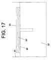
- a carbonaceous feed stock is then introduced into the process chamber, and a plasma from a plasma source (not shown) is applied at an angle to the layer 22 to cause the growth of a layer of nanofibres 23, aligned with the direction of the electromagnetic field.
- An angle of 45° is shown in Figure 17 , although this angle may be as low as 5° if required.
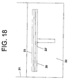
- nanofibres 23 of a suitable length have been grown, the plasma power source and gas supply are turned off, inert gas in the chamber is purged, and the platform 20 is lowered as shown in Figure 18 .
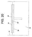
- the platform 20 is then lifted up to the position just above the surface of the bath 21 shown in Figure 19 in which a mound 24 of resin impregnates the layer of nanofibres 23.
- the doctor blade then wipes across the mound 23 to form a uniformly thick layer 24' of resin shown in Figure 20 .
- the laser is then turned on and scanned across the layer 24' to cause the resin to cure in a desired shape.
- the layer 24' is shown in Figure 20 above the layer of nanofibres 23, but in practice the layer 24' may be made sufficiently thin such that after curing it only impregnates the matrix through a lower part of its thickness, in a similar manner to the layer 13' shown in Figure 6 , thus giving partial overlap with the next layer of nanofibres.
- the process is then be repeated further to form a bulk material.
Landscapes
- Chemical & Material Sciences (AREA)
- Engineering & Computer Science (AREA)
- Materials Engineering (AREA)
- Manufacturing & Machinery (AREA)
- Health & Medical Sciences (AREA)
- Chemical Kinetics & Catalysis (AREA)
- Medicinal Chemistry (AREA)
- Polymers & Plastics (AREA)
- Organic Chemistry (AREA)
- Composite Materials (AREA)
- Nanotechnology (AREA)
- General Physics & Mathematics (AREA)
- Condensed Matter Physics & Semiconductors (AREA)
- Physics & Mathematics (AREA)
- Crystallography & Structural Chemistry (AREA)
- Mechanical Engineering (AREA)
- Inorganic Chemistry (AREA)
- General Chemical & Material Sciences (AREA)
- Reinforced Plastic Materials (AREA)
- Catalysts (AREA)
- Compositions Of Macromolecular Compounds (AREA)
- Chemical Vapour Deposition (AREA)
- Manufacture Of Alloys Or Alloy Compounds (AREA)
- Physical Vapour Deposition (AREA)
- Inorganic Fibers (AREA)
- Laminated Bodies (AREA)
- Carbon And Carbon Compounds (AREA)
Abstract
Description
- The present invention relates to a method of manufacturing a composite material.
- Nanocomposites based on carbon nanotubes are described in E. T. Thostenson and T-W. Chou, "Aligned Multi-Walled Carbon Nanotube-Reinforced Composites: Processing and Mechanical Characterization," Journal of Physics D: Applied Physics, 35(16) L77-L80 (2002). According to this paper, one of the most significant challenges towards improving the properties of the nanocomposite is to obtain a uniform dispersion of nanotubes within the polymer matrix. The solution presented in this paper is a micro-scale twin-screw extruder.
- "Manufacturing processes for advanced composites, Ply Collation: A Major Cost Driver", Campbell et al., Manufacturing Processes for Advanced Composites (1 January 2004) describes a method of flat ply collation and vacuum forming.
-
US2005/0167647 describes a thermal interface material which includes a macromolecular material with a plurality of carbon nanotubes embedded uniformly therein. - A first aspect of the invention provides a method of manufacturing a composite material, the method comprising:
- manufacturing two or more sheets of composite material, each sheet being manufactured by growing a layer of reinforcement; and impregnating the layer with a matrix;
- laying the sheets together to form a laminate structure; and
- moulding the laminate structure.
- The invention may be used to form sheets (either single layer or multi-layer) which are processed in a similar manner to a conventional "prepreg", that is by laying the sheets together to form a laminate structure; and moulding the laminate structure to form a composite element.
- Each layer of reinforcement may be manufactured by forming a layer of catalyst particles to catalyse the growth of the reinforcement layers by spraying droplets of liquid onto a surface, the liquid containing the catalyst particles in suspension or solution.
- The method may include growing each layer of reinforcement with a packing density which varies across the layer
- The layer of reinforcement may be grown in-situ by an arc discharge process, in which stock material contained in a negative electrode sublimates because of the high temperatures caused by the discharge. Alternatively the layer of reinforcement may be grown in-situ by a laser ablation process, in which a pulsed laser vaporizes a target in a high temperature reactor while an inert gas is bled into a process chamber. The reinforcement layer develops on the cooler surfaces of the reactor, as the vaporized material condenses. In the case of arc discharge or laser ablation, the elements (such as carbon nanotubes) making up the reinforcement layer are formed in a gaseous state, and in-situ growth of the layer occurs by condensation of the elements on a substrate. However a problem with such arc discharge and laser ablation processes is that they are not suited to high volume production, and tend to require high temperatures. Therefore preferably the method further comprises forming a layer of catalyst particles to catalyse the growth of the reinforcement, for instance as part of a chemical vapour deposition process. This enables growth to be carried out at lower temperatures, typically in the range of 25-500°C. In this case the layer grows by in-situ growth of the elements making up the reinforcement layer, instead of growing by accumulation of pre-formed elements.
- The catalyst particles may be deposited directly, through the precipitation of metal salts held in solution in water, oil or alcohol, or they may be deposited as a colloid suspension, for instance from a printing head.
- Typically the method further comprises heating the matrix during impregnation, using a laser or other heat source. The matrix material is typically deposited as a layer, for instance a powder layer which is heated in-situ to impregnate the reinforcement.
- Impregnation typically occurs by a process of capillary action.
- The matrix may be a metal such as Titanium, or a polymer such as a thermosetting resin or a thermoplastic material such as polyetheretherketone (PEEK).
- The reinforcement layer typically comprises reinforcement elements having an elongate structure such as tubes, fibres or plates. The reinforcement elements may be solid or tubular. For instance the reinforcement elements may be single walled carbon nanotubes; multi-walled carbon nanotubes; or carbon nanotubes coated with a layer of amorphous carbon.
- Preferably the reinforcement layer comprises reinforcement elements having an aspect ratio greater than 100.
- Preferably the reinforcement layer comprises reinforcement elements having a diameter less than 100 nm.
- The reinforcement may be formed of any material such as silicon carbide or alumina, but preferably the reinforcement layer comprises carbon fibres. This is preferred due to the strength and stiffness of the carbon-carbon bond.
- Embodiments of the invention will now be described with reference to the accompanying drawings, in which:
-
Figures 1-10 show various steps in the manufacture of a multi-layer thermoplastic matrix composite material; -
Figures 11-13 show various steps in the manufacture of a thin film thermoplastic matrix composite material; and -
Figures 14-20 show various steps in the manufacture of a thermosetting matrix composite material. - The apparatus 1 shown in
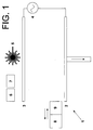
Figure 1 (which is suitable for use with manufacturing methods according to the present invention) is housed within a process chamber (not shown). A negativeplasma source electrode 2 and a positiveplasma source electrode 3 are connected by apower source 4. Alaser 5 is positioned above thepositive plasma source 3, and is associated with a raster scanning mechanism (not shown). Agas supply 6 can be turned on and off to supply a pre-heated process gas to the chamber, such as CH4/H2. Asecond gas supply 7 can be turned on and off to supply an inert gas such as N2 to the process chamber. The inert gas is preheated to a temperature at or just below the melting point of the matrix material. Theelectrode 2 is also heated by a heating element (not shown) to a similar temperature. - A
heated hopper 8 and a cooled ink-jet printing head 9 are mounted on a transport mechanism (not shown) which can move thehopper 8 and printinghead 9 from left to right inFigure 1 (that is, from one end of thenegative plasma source 2 to the other). A transport mechanism (not shown) is provided for driving thenegative plasma source 2 up and down. -
Figures 1-10 are side views of the apparatus, and thus do not show the third (width) dimension out of the plane of the figures. However, theelectrodes laser 5,hopper 8 andprinting head 9 will extend across the width of the apparatus. - The process steps described below in relation to
Figs. 1-10 do not fall within the scope of the present invention. - In a first process step shown in
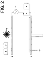
Figure 2 , the hopper (8) is filled with a polymer powder such as polyetheretherketone (PEEK). Thehopper 8 is moved across thenegative plasma source 2, and a dispensing orifice (not shown) in thehopper 8 is opened to deposit alayer 10 of polymer powder. Thus thesource 2 also acts as a bed or platform for the additive layer manufacturing process. The orifice is then closed. The inert gas prevents oxidation of the polymer. Thelaser 5 is turned on and the raster mechanism scans the beam across thelayer 10 to consolidate thelayer 10. The heating effect of the laser beam causes thepolymer layer 10 to melt. A shutter (not shown) in the path of the laser beam is opened and closed selectively to modulate the beam as it is scanned over thelayer 10. Thus thelayer 10 is consolidated only in the areas required to form a desired shape. More specifically, the shutter is opened and closed in accordance with a computer-aided design (CAD) model which defines a series of slices through the desired three-dimensional shape. - In a second process step shown in
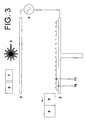
Figure 3 , theprinting head 9 is moved across thelayer 10 to deposit an array ofcatalyst particles 11. Theprinting head 9 sprays an array of colloid drops onto thelayer 10, and as the colloid evaporates in the high temperature inert gas environment,metal catalyst particles 11 suspended in the colloid drops are deposited. Thecatalyst particles 11 may be, for example a metal, preferably transition metals Fe, Ni or Co, or alloys thereof; and the colloid liquid may be, for example alcohol, water, oil, or a mixture thereof. A fluid-based cooling system (not shown) cools theprinting head 9 and a reservoir (not shown) containing the printing fluid to prevent the colloid liquid from boiling before it is printed. The printing orifice of the printing head 9 (which emits the spray of droplets) is positioned sufficiently close to thelayer 10 to ensure that the colloid liquid does not evaporate deleteriously in flight, before hitting thelayer 10. - Although the
catalyst particles 11 are shown inFigure 3 for purposes of illustration with a regular spacing along the length of thelayer 10, the spacing between the particles will be essentially random in both the length and width dimensions. - The diameter of each catalyst particle is typically in the range of 1 nm-1 µm, and the catalyst particles may be close-packed, or spaced apart.
- In a third process step shown in
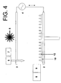
Figure 4 , the carbonaceous feed stock is introduced from thegas supply 6 and thepower source 4 is turned on to generate a plasma between theelectrodes nanofibres 12, aligned with the direction of the electromagnetic field between theelectrodes nanofibres 12 is produced, eachnanofibre 12 carrying acatalyst particle 11 at its tip. - The catalyst particles and plasma enable the nanofibre growth to occur at a relatively low temperature, lower than the melting point of the matrix.
- The diameter of the nanofibres is typically in the range of 1 nm-1 µm. Thus, although described as "nanofibres", the diameter of the
fibres 12 may exceed 100 nm if desired. - Once
nanofibres 12 of a suitable length have been grown, theplasma power source 4 andgas supply 6 are turned off, the inert gas is purged, and in a fourth process step shown inFigure 5 , theplatform 2 is lowered and thehopper 8 is moved along the layer ofnanofibres 12 to deposit afurther layer 13 of polymer powder. The polymer powder size is typically three orders of magnitude larger than the diameter of thenanofibres 12 and significantly greater than the spaces between thenanofibres 12. As a result, thepolymer powder layer 13 sits on top of the layer ofnanofibres 12 as shown inFigure 5 . Thelayer 13 has a thickness which is some multiple of the polymer powder size of 20-50 µm - typically of the order of 0.2-0.5 mm. - In a fifth process step shown in
Figure 6 , thelaser 5 is turned on and the raster mechanism scans the beam across thelayer 13 to form a consolidated layer 13'. During the raster scan, the shutter is opened and closed as required to form the consolidated layer 13' in a desired shape. - The thickness of the
unconsolidated polymer layer 13 is selected so that the layer ofnanofibres 12 is only partially impregnated with the matrix through a lower part of its thickness, leaving an upper part of the layer ofnanofibres 12 exposed as shown inFigure 6 . By way of example, the thickness of theunconsolidated layer 13 shown inFigure 5 may be in the range of 0.2-0.5 mm, and the thickness of the consolidated layer 13' shown inFigure 6 may be in the range of 0.1-0.25 mm. Thus in this case thenanofibres 12, being slightly longer than the layer of consolidated matrix 13', will have lengths exceeding 0.1 mm and aspect ratios exceeding 100. Although the ratio between the length of thefibres 12 and the thickness of the consolidated layer 13' is of the order of 2:1 inFigure 6 , this is for illustrative purposes only and in practice a much smaller degree of overlap (for instance a ratio of 1.05:1) will be required to give significant interlayer reinforcement. - The laser is then turned off and the five process steps shown in
Figures 2-6 are repeated to build up a series of layers of nanofibres; each layer being impregnated with a matrix before depositing the next layer. - Thus in the first repeat, a second layer of
catalyst particles 14 is deposited as shown inFigure 7 . InFigure 7 thecatalyst particles 14 are shown in a regular array, interleaved with the array ofnanofibres 12. However the distribution ofmatrix particles 14 will be essentially random in both the length and width dimensions. - As shown in
Figure 8 , a second layer ofnanofibres 15 is then grown, catalysed by thecatalyst particles 14. Note that the second layer ofnanofibres 15 partially overlaps with the previous layer ofnanofibres 12. This results in "interlaminar" reinforcement as well as "intralaminar" reinforcement. Although the second layer is shown inFigure 8 with vertically extendingnanofibres 15, in an alternative embodiment thesecond plasma source 3 may be moved relative to theplatform 2 so that the nanofibres in the second layer are aligned in a different direction, for instance at an acute angle such as 45° to the vertical. The electromagnetic field may be re-oriented for each successive layer of nanofibres if desired. A transport mechanism (not shown) is provided to move theplasma source electrode 3 relative to theplatform 2 into the position required. Equivalently, a mechanism (not shown) may be provided to move theplatform 2, or rotate it, to give the desired angle of electro-magnetic field. - As shown in
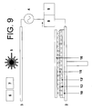
Figure 9 , thenegative plasma source 2 is lowered again and afurther layer 16 of polymer powder deposited on top of the layer ofnanofibres 15. - As shown in
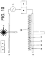
Figure 10 , thelayer 16 is then consolidated by thelaser 5 to form a consolidated layer 16'. - The process is then repeated as required, with each layer of nanofibres being selectively impregnated to form a cross-section with a desired two-dimensional shape and size. Once the structure has been formed, unconsolidated powder is removed, leaving an element with a desired three dimensional shape.
- In the embodiment described above, a respective layer of
catalyst particles catalyst particles 11 may be re-used to catalyse a succession of layers of fibres which grow end-to-end, instead of growing as a succession of discrete fibres with the overlapping configuration shown inFigure 8 . - Optionally the
printing head 9 may be modulated selectively so as to deposit each layer of colloid drops with a desired shape and/or packing density. This enables each layer of nanotubes to be grown with a different shape and/or packing density. Optionally the packing density of the colloid drops (and hence the packing density of the nanotubes) may also vary across the layer (in the width and/or length direction) as well as varying between layers. - Instead of depositing the matrix powder with a
hopper 8, the layers of matrix powder may be applied by a roller or other feed system which spreads the layer across the substrate. - In the process shown in
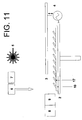
Figures 1-10 (that process not forming part of the present invention), a bulk composite material is formed by depositing a series of layers of nanotubes, each layer being impregnated before growth of the next layer. In the alternative process shown inFigures 11-13 (showing embodiments of the present invention), the same apparatus may be used to form a sheet with only a single layer of nanotubes. - As shown in
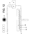
Figure 11 , after depositing a layer of catalyst particles, a layer ofnanotubes 17 is grown at an angle to thesubstrate matrix layer 10 by moving thepositive plasma source 3 to the position shown. As shown inFigure 12 , a layer ofmatrix 18 is then deposited, and consolidated to impregnate the layer ofnanotubes 17 as shown inFigure 13 . The resulting sheet is then removed from the process chamber, and can be used in the same manner as a conventional "prepreg". That is, a number of such sheets can be laid together to form a laminate structure, cut to shape and moulded to form a composite element. -
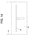
Figures 14-20 show an additive layer manufacturing system for manufacturing a composite with a thermosetting epoxy resin matrix (instead of the thermoplastic matrix used in the apparatus ofFigures 1-13 ). The system shown inFigures 14-20 incorporates all of the elements of the system ofFigure 1 (except the hopper 8) but these elements are not shown inFigures 14-20 for purposes of clarity. - In a first process step shown in
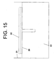
Figure 14 , aplatform 20 is immersed in abath 21 of liquidepoxy resin 22. The platform is then lifted up to a position just above the surface of thebath 21 as shown inFigure 15 in which amound 22 of resin is supported by theplatform 20. A doctor blade (not shown) wipes across themound 22 to leave a uniformly thick layer 22' of resin shown inFigure 16 . A laser (not shown) is then turned on and scanned across the layer 22' to cause the resin to cure in a desired shape. - A printing head (not shown) is then moved across the layer 22' to deposit an array of catalyst particles (not shown). A carbonaceous feed stock is then introduced into the process chamber, and a plasma from a plasma source (not shown) is applied at an angle to the
layer 22 to cause the growth of a layer ofnanofibres 23, aligned with the direction of the electromagnetic field. An angle of 45° is shown inFigure 17 , although this angle may be as low as 5° if required. - Once
nanofibres 23 of a suitable length have been grown, the plasma power source and gas supply are turned off, inert gas in the chamber is purged, and theplatform 20 is lowered as shown inFigure 18 . - The
platform 20 is then lifted up to the position just above the surface of thebath 21 shown inFigure 19 in which amound 24 of resin impregnates the layer ofnanofibres 23. The doctor blade then wipes across themound 23 to form a uniformly thick layer 24' of resin shown inFigure 20 . The laser is then turned on and scanned across the layer 24' to cause the resin to cure in a desired shape. Note that the layer 24' is shown inFigure 20 above the layer ofnanofibres 23, but in practice the layer 24' may be made sufficiently thin such that after curing it only impregnates the matrix through a lower part of its thickness, in a similar manner to the layer 13' shown inFigure 6 , thus giving partial overlap with the next layer of nanofibres. - The process is then be repeated further to form a bulk material.
- It should be noted that
Figures 1-20 are not to scale, and thus the relative dimensions of the various elements may vary significantly from those shown. - Although the invention has been described above with reference to one or more preferred embodiments, it will be appreciated that various changes or modifications may be made without departing from the scope of the invention as defined in the appended claims.
Claims (15)
- A method of manufacturing a composite material, the method comprising:manufacturing two or more sheets of composite material;laying the sheets together to form a laminate structure; andmoulding the laminate structure,characterised in that the two or more sheets of composite material are each manufactured by: growing a layer of reinforcement (17); and impregnating the layer with a matrix (18).
- The method of claim 1 further comprising heating the matrix during impregnation.
- The method of claim 2 wherein the matrix is heated by a laser beam (5).
- The method of claim 2 or 3 wherein the layer of reinforcement is impregnated by depositing a layer of matrix material on the layer of reinforcement; and heating at least part of the layer of matrix material.
- The method of claim 4 wherein the layer of matrix material is a powder.
- The method of any preceding claim wherein the layer of reinforcement is impregnated by capillary action.
- The method of any preceding claim wherein the matrix is a polymer.
- The method of any preceding claim wherein the matrix is thermoplastic.
- The method of any of claims 1 to 7 wherein the matrix is thermosetting.
- The method of any preceding claim wherein the reinforcement layer comprises carbon fibres.
- The method of any preceding claim wherein each sheet has only a single layer of reinforcement.
- The method of any preceding claim wherein the sheets are laid together to form the laminate structure, cut to shape and moulded to form a composite element.
- The method of any preceding claim wherein each layer of reinforcement is manufactured by forming a layer of catalyst particles (11) to catalyse the growth of the reinforcement layers by spraying droplets of liquid onto a surface, the liquid containing the catalyst particles in suspension or solution.
- The method of claim 13 wherein the liquid contains the catalyst particles in a colloid suspension.
- The method of any preceding claim further comprising growing each layer of reinforcement with a packing density which varies across the layer.
Applications Claiming Priority (3)
| Application Number | Priority Date | Filing Date | Title |
|---|---|---|---|
| US82456506P | 2006-09-05 | 2006-09-05 | |
| GBGB0617460.1A GB0617460D0 (en) | 2006-09-05 | 2006-09-05 | Method of manufacturing composite material |
| EP07789385A EP2061644B1 (en) | 2006-09-05 | 2007-08-29 | Method of manufacturing composite material by growing of a layer of reinforcement and related apparatus |
Related Parent Applications (1)
| Application Number | Title | Priority Date | Filing Date |
|---|---|---|---|
| EP07789385.7 Division | 2007-08-29 |
Publications (2)
| Publication Number | Publication Date |
|---|---|
| EP2409827A1 EP2409827A1 (en) | 2012-01-25 |
| EP2409827B1 true EP2409827B1 (en) | 2012-11-28 |
Family
ID=37232391
Family Applications (2)
| Application Number | Title | Priority Date | Filing Date |
|---|---|---|---|
| EP07789385A Not-in-force EP2061644B1 (en) | 2006-09-05 | 2007-08-29 | Method of manufacturing composite material by growing of a layer of reinforcement and related apparatus |
| EP11185691A Not-in-force EP2409827B1 (en) | 2006-09-05 | 2007-08-29 | Method of manufacturing composite material |
Family Applications Before (1)
| Application Number | Title | Priority Date | Filing Date |
|---|---|---|---|
| EP07789385A Not-in-force EP2061644B1 (en) | 2006-09-05 | 2007-08-29 | Method of manufacturing composite material by growing of a layer of reinforcement and related apparatus |
Country Status (10)
| Country | Link |
|---|---|
| US (1) | US20100004388A1 (en) |
| EP (2) | EP2061644B1 (en) |
| JP (2) | JP5587602B2 (en) |
| CN (2) | CN102774016A (en) |
| AT (1) | ATE530332T1 (en) |
| BR (1) | BRPI0716167A2 (en) |
| CA (1) | CA2661746C (en) |
| GB (1) | GB0617460D0 (en) |
| RU (1) | RU2448832C2 (en) |
| WO (1) | WO2008029179A2 (en) |
Families Citing this family (9)
| Publication number | Priority date | Publication date | Assignee | Title |
|---|---|---|---|---|
| GB0715164D0 (en) * | 2007-08-06 | 2007-09-12 | Airbus Uk Ltd | Method and apparatus for manufacturing a composite material |
| GB0715990D0 (en) * | 2007-08-16 | 2007-09-26 | Airbus Uk Ltd | Method and apparatus for manufacturing a component from a composite material |
| RU2459888C2 (en) * | 2010-11-30 | 2012-08-27 | Открытое акционерное общество "Композит" (ОАО "Композит") | Method of making shell structures |
| RU2478562C1 (en) * | 2011-08-11 | 2013-04-10 | Государственное образовательное учреждение высшего профессионального образования "Владимирский государственный университет имени Александра Григорьевича и Николая Григорьевича Столетовых" (ВлГУ) | Method of obtaining fibres in electric uniform field |
| RU2567283C2 (en) * | 2013-11-18 | 2015-11-10 | Александр Григорьевич Григорьянц | Method and device for producing of carbon nanotubes |
| RU2641134C1 (en) * | 2016-07-14 | 2018-01-16 | Федеральное государственное бюджетное образовательное учреждение высшего образования "Башкирский государственный университет" | Electrically conductive metal-filled polymer compound for 3d-printing (versions) |
| RU2641921C2 (en) * | 2016-07-14 | 2018-01-23 | Федеральное государственное бюджетное образовательное учреждение высшего образования "Башкирский государственный университет" | Electrically conductive metal-filled polymer compound for 3d-printing (versions) |
| WO2018081357A1 (en) * | 2016-10-26 | 2018-05-03 | Purdue Research Foundation | Roll-to-roll manufacturing machines and methods for producing nanostructures-containing polymer films |
| DE102018102061B3 (en) * | 2018-01-30 | 2019-03-14 | Brandenburgische Technische Universität Cottbus-Senftenberg | Extrusion apparatus and method for producing carbon fiber reinforced plastic semi-finished products |
Family Cites Families (39)
| Publication number | Priority date | Publication date | Assignee | Title |
|---|---|---|---|---|
| US4560603A (en) * | 1983-10-27 | 1985-12-24 | Ltv Aerospace And Defense Company | Composite matrix with oriented whiskers |
| RU2048295C1 (en) * | 1992-01-24 | 1995-11-20 | Юрий Иванович Кадун | Method for making laminated article from composite material |
| US5837081A (en) * | 1993-04-07 | 1998-11-17 | Applied Sciences, Inc. | Method for making a carbon-carbon composite |
| US6156256A (en) * | 1998-05-13 | 2000-12-05 | Applied Sciences, Inc. | Plasma catalysis of carbon nanofibers |
| US6863942B2 (en) * | 1998-06-19 | 2005-03-08 | The Research Foundation Of State University Of New York | Free-standing and aligned carbon nanotubes and synthesis thereof |
| US6265466B1 (en) * | 1999-02-12 | 2001-07-24 | Eikos, Inc. | Electromagnetic shielding composite comprising nanotubes |
| AUPP976499A0 (en) * | 1999-04-16 | 1999-05-06 | Commonwealth Scientific And Industrial Research Organisation | Multilayer carbon nanotube films |
| US6214276B1 (en) * | 1999-05-18 | 2001-04-10 | Creo Srl | Method of forming objects from thermosensitive composition |
| EP1059266A3 (en) * | 1999-06-11 | 2000-12-20 | Iljin Nanotech Co., Ltd. | Mass synthesis method of high purity carbon nanotubes vertically aligned over large-size substrate using thermal chemical vapor deposition |
| KR100673367B1 (en) * | 1999-10-27 | 2007-01-24 | 윌리엄 마쉬 라이스 유니버시티 | Macroscopic ordered assembly of carbon nanotubes |
| US6923946B2 (en) * | 1999-11-26 | 2005-08-02 | Ut-Battelle, Llc | Condensed phase conversion and growth of nanorods instead of from vapor |
| US6495116B1 (en) * | 2000-04-10 | 2002-12-17 | Lockheed Martin Corporation | Net shape manufacturing using carbon nanotubes |
| AU2002236431A1 (en) * | 2000-08-23 | 2002-05-21 | A. Kuper Cynthia | Method for utilizing sol-gel processing in the production of a macroscopic two or three dimensionally ordered array of single wall nanotubes (swnts) |
| US6428890B1 (en) * | 2001-06-07 | 2002-08-06 | National Cheng Kung University | Polymer matrix composite and method for making the same |
| US6921462B2 (en) * | 2001-12-17 | 2005-07-26 | Intel Corporation | Method and apparatus for producing aligned carbon nanotube thermal interface structure |
| US6746768B2 (en) * | 2001-12-26 | 2004-06-08 | Advanced Energy Technology Inc. | Thermal interface material |
| US6913794B2 (en) * | 2002-01-14 | 2005-07-05 | Coherent, Inc. | Diode-laser curing of liquid epoxide encapsulants |
| JP3962862B2 (en) * | 2002-02-27 | 2007-08-22 | 日立造船株式会社 | Conductive material using carbon nanotube and method for producing the same |
| US6780506B2 (en) * | 2002-04-26 | 2004-08-24 | Sumitomo Chemical Company, Limited | Fiber-reinforced polyolefin resin composite and molded article obtained from the same |
| FR2844510B1 (en) * | 2002-09-12 | 2006-06-16 | Snecma Propulsion Solide | THREE-DIMENSIONAL FIBROUS STRUCTURE OF REFRACTORY FIBERS, PROCESS FOR THE PRODUCTION THEREOF AND APPLICATION TO THERMOSTRUCTURAL COMPOSITE MATERIALS |
| US20040071951A1 (en) * | 2002-09-30 | 2004-04-15 | Sungho Jin | Ultra-high-density information storage media and methods for making the same |
| US20030154865A1 (en) * | 2002-10-16 | 2003-08-21 | Zornes David A. | Nano coupling magnetoadsorbent |
| US6841003B2 (en) * | 2002-11-22 | 2005-01-11 | Cdream Display Corporation | Method for forming carbon nanotubes with intermediate purification steps |
| JP2004298357A (en) * | 2003-03-31 | 2004-10-28 | Mizuno Technics Kk | Golf shaft |
| US7118941B2 (en) * | 2003-06-25 | 2006-10-10 | Intel Corporation | Method of fabricating a composite carbon nanotube thermal interface device |
| JP2005041835A (en) * | 2003-07-24 | 2005-02-17 | Fuji Xerox Co Ltd | Carbon nanotube structure, method for producing the same, carbon nanotube transfer and solution |
| JP2007501525A (en) * | 2003-08-04 | 2007-01-25 | ナノシス・インコーポレイテッド | Nanowire composites and systems and methods for making electronic substrates derived therefrom |
| US20050116336A1 (en) * | 2003-09-16 | 2005-06-02 | Koila, Inc. | Nano-composite materials for thermal management applications |
| US20050061496A1 (en) * | 2003-09-24 | 2005-03-24 | Matabayas James Christopher | Thermal interface material with aligned carbon nanotubes |
| US7181836B2 (en) * | 2003-12-19 | 2007-02-27 | General Electric Company | Method for making an electrode structure |
| US20050169831A1 (en) * | 2004-02-04 | 2005-08-04 | Montgomery Stephen W. | Three-dimensional nanotube structure |
| CN100383213C (en) * | 2004-04-02 | 2008-04-23 | 清华大学 | Thermal interface material and its manufacturing method |
| TWI293062B (en) * | 2004-04-19 | 2008-02-01 | Japan Science & Tech Agency | Assembly of carbon microstructures, aggregate of carbon microstructures, and use and manufacturing method of those |
| US20050279274A1 (en) * | 2004-04-30 | 2005-12-22 | Chunming Niu | Systems and methods for nanowire growth and manufacturing |
| US20060025515A1 (en) * | 2004-07-27 | 2006-02-02 | Mainstream Engineering Corp. | Nanotube composites and methods for producing |
| US7129097B2 (en) * | 2004-07-29 | 2006-10-31 | International Business Machines Corporation | Integrated circuit chip utilizing oriented carbon nanotube conductive layers |
| JP2006069165A (en) * | 2004-09-06 | 2006-03-16 | Japan Science & Technology Agency | Carbon nanotube composite sheet and its production method |
| US20060083927A1 (en) * | 2004-10-15 | 2006-04-20 | Zyvex Corporation | Thermal interface incorporating nanotubes |
| AU2006312250B2 (en) * | 2005-06-28 | 2011-07-07 | The Board Of Regents Of The University Of Oklahoma | Methods for growing and harvesting carbon nanotubes |
-
2006
- 2006-09-05 GB GBGB0617460.1A patent/GB0617460D0/en not_active Ceased
-
2007
- 2007-08-29 CN CN2012102875795A patent/CN102774016A/en active Pending
- 2007-08-29 EP EP07789385A patent/EP2061644B1/en not_active Not-in-force
- 2007-08-29 US US12/439,267 patent/US20100004388A1/en not_active Abandoned
- 2007-08-29 CA CA2661746A patent/CA2661746C/en not_active Expired - Fee Related
- 2007-08-29 BR BRPI0716167-0A2A patent/BRPI0716167A2/en not_active IP Right Cessation
- 2007-08-29 CN CN200780032906XA patent/CN101511570B/en not_active Expired - Fee Related
- 2007-08-29 AT AT07789385T patent/ATE530332T1/en not_active IP Right Cessation
- 2007-08-29 WO PCT/GB2007/050510 patent/WO2008029179A2/en active Application Filing
- 2007-08-29 RU RU2009110970/05A patent/RU2448832C2/en not_active IP Right Cessation
- 2007-08-29 EP EP11185691A patent/EP2409827B1/en not_active Not-in-force
- 2007-08-29 JP JP2009527212A patent/JP5587602B2/en not_active Expired - Fee Related
-
2013
- 2013-03-28 JP JP2013068680A patent/JP5588038B2/en not_active Expired - Fee Related
Also Published As
| Publication number | Publication date |
|---|---|
| CN102774016A (en) | 2012-11-14 |
| BRPI0716167A2 (en) | 2013-09-17 |
| GB0617460D0 (en) | 2006-10-18 |
| EP2061644A2 (en) | 2009-05-27 |
| JP5588038B2 (en) | 2014-09-10 |
| CA2661746A1 (en) | 2008-03-13 |
| ATE530332T1 (en) | 2011-11-15 |
| JP5587602B2 (en) | 2014-09-10 |
| CA2661746C (en) | 2015-03-31 |
| JP2010502808A (en) | 2010-01-28 |
| EP2061644B1 (en) | 2011-10-26 |
| RU2448832C2 (en) | 2012-04-27 |
| CN101511570B (en) | 2012-10-03 |
| JP2013144809A (en) | 2013-07-25 |
| RU2009110970A (en) | 2010-10-20 |
| EP2409827A1 (en) | 2012-01-25 |
| WO2008029179A3 (en) | 2008-04-24 |
| WO2008029179A2 (en) | 2008-03-13 |
| CN101511570A (en) | 2009-08-19 |
| US20100004388A1 (en) | 2010-01-07 |
Similar Documents
| Publication | Publication Date | Title |
|---|---|---|
| EP2061643B1 (en) | Method of manufacturing composite material by growing of layers of reinforcement | |
| EP2409827B1 (en) | Method of manufacturing composite material | |
| RU2447994C2 (en) | Method of producing composite material by growing reinforcing layers and device to this end | |
| CA2695847C (en) | Method and apparatus for manufacturing a composite material | |
| US8486321B2 (en) | Print through reduction in long fiber reinforced composites by addition of carbon nanotubes | |
| US20120280430A1 (en) | Composite tooling containing carbon nanotubes and production of parts therefrom | |
| US20240217173A1 (en) | Method and system for dynamic capillary-driven additive manufacturing of continuous fiber composite | |
| CN114654845B (en) | Polymer sandwich structure with enhanced thermal conductivity and method for manufacturing same | |
| EP2683542B1 (en) | Method of manufacturing a composite material and composite material |
Legal Events
| Date | Code | Title | Description |
|---|---|---|---|
| AC | Divisional application: reference to earlier application |
Ref document number: 2061644 Country of ref document: EP Kind code of ref document: P |
|
| AK | Designated contracting states |
Kind code of ref document: A1 Designated state(s): AT BE BG CH CY CZ DE DK EE ES FI FR GB GR HU IE IS IT LI LT LU LV MC MT NL PL PT RO SE SI SK TR |
|
| PUAI | Public reference made under article 153(3) epc to a published international application that has entered the european phase |
Free format text: ORIGINAL CODE: 0009012 |
|
| 17P | Request for examination filed |
Effective date: 20120508 |
|
| GRAP | Despatch of communication of intention to grant a patent |
Free format text: ORIGINAL CODE: EPIDOSNIGR1 |
|
| GRAS | Grant fee paid |
Free format text: ORIGINAL CODE: EPIDOSNIGR3 |
|
| GRAA | (expected) grant |
Free format text: ORIGINAL CODE: 0009210 |
|
| AC | Divisional application: reference to earlier application |
Ref document number: 2061644 Country of ref document: EP Kind code of ref document: P |
|
| AK | Designated contracting states |
Kind code of ref document: B1 Designated state(s): AT BE BG CH CY CZ DE DK EE ES FI FR GB GR HU IE IS IT LI LT LU LV MC MT NL PL PT RO SE SI SK TR |
|
| REG | Reference to a national code |
Ref country code: GB Ref legal event code: FG4D |
|
| REG | Reference to a national code |
Ref country code: CH Ref legal event code: EP |
|
| REG | Reference to a national code |
Ref country code: AT Ref legal event code: REF Ref document number: 585913 Country of ref document: AT Kind code of ref document: T Effective date: 20121215 |
|
| REG | Reference to a national code |
Ref country code: IE Ref legal event code: FG4D |
|
| REG | Reference to a national code |
Ref country code: DE Ref legal event code: R096 Ref document number: 602007027070 Country of ref document: DE Effective date: 20130124 |
|
| REG | Reference to a national code |
Ref country code: AT Ref legal event code: MK05 Ref document number: 585913 Country of ref document: AT Kind code of ref document: T Effective date: 20121128 |
|
| REG | Reference to a national code |
Ref country code: NL Ref legal event code: VDEP Effective date: 20121128 |
|
| REG | Reference to a national code |
Ref country code: LT Ref legal event code: MG4D |
|
| PG25 | Lapsed in a contracting state [announced via postgrant information from national office to epo] |
Ref country code: ES Free format text: LAPSE BECAUSE OF FAILURE TO SUBMIT A TRANSLATION OF THE DESCRIPTION OR TO PAY THE FEE WITHIN THE PRESCRIBED TIME-LIMIT Effective date: 20130311 Ref country code: FI Free format text: LAPSE BECAUSE OF FAILURE TO SUBMIT A TRANSLATION OF THE DESCRIPTION OR TO PAY THE FEE WITHIN THE PRESCRIBED TIME-LIMIT Effective date: 20121128 Ref country code: LT Free format text: LAPSE BECAUSE OF FAILURE TO SUBMIT A TRANSLATION OF THE DESCRIPTION OR TO PAY THE FEE WITHIN THE PRESCRIBED TIME-LIMIT Effective date: 20121128 Ref country code: SE Free format text: LAPSE BECAUSE OF FAILURE TO SUBMIT A TRANSLATION OF THE DESCRIPTION OR TO PAY THE FEE WITHIN THE PRESCRIBED TIME-LIMIT Effective date: 20121128 |
|
| PG25 | Lapsed in a contracting state [announced via postgrant information from national office to epo] |
Ref country code: PL Free format text: LAPSE BECAUSE OF FAILURE TO SUBMIT A TRANSLATION OF THE DESCRIPTION OR TO PAY THE FEE WITHIN THE PRESCRIBED TIME-LIMIT Effective date: 20121128 Ref country code: BE Free format text: LAPSE BECAUSE OF FAILURE TO SUBMIT A TRANSLATION OF THE DESCRIPTION OR TO PAY THE FEE WITHIN THE PRESCRIBED TIME-LIMIT Effective date: 20121128 Ref country code: LV Free format text: LAPSE BECAUSE OF FAILURE TO SUBMIT A TRANSLATION OF THE DESCRIPTION OR TO PAY THE FEE WITHIN THE PRESCRIBED TIME-LIMIT Effective date: 20121128 Ref country code: PT Free format text: LAPSE BECAUSE OF FAILURE TO SUBMIT A TRANSLATION OF THE DESCRIPTION OR TO PAY THE FEE WITHIN THE PRESCRIBED TIME-LIMIT Effective date: 20130328 Ref country code: GR Free format text: LAPSE BECAUSE OF FAILURE TO SUBMIT A TRANSLATION OF THE DESCRIPTION OR TO PAY THE FEE WITHIN THE PRESCRIBED TIME-LIMIT Effective date: 20130301 Ref country code: SI Free format text: LAPSE BECAUSE OF FAILURE TO SUBMIT A TRANSLATION OF THE DESCRIPTION OR TO PAY THE FEE WITHIN THE PRESCRIBED TIME-LIMIT Effective date: 20121128 |
|
| PG25 | Lapsed in a contracting state [announced via postgrant information from national office to epo] |
Ref country code: AT Free format text: LAPSE BECAUSE OF FAILURE TO SUBMIT A TRANSLATION OF THE DESCRIPTION OR TO PAY THE FEE WITHIN THE PRESCRIBED TIME-LIMIT Effective date: 20121128 |
|
| PG25 | Lapsed in a contracting state [announced via postgrant information from national office to epo] |
Ref country code: EE Free format text: LAPSE BECAUSE OF FAILURE TO SUBMIT A TRANSLATION OF THE DESCRIPTION OR TO PAY THE FEE WITHIN THE PRESCRIBED TIME-LIMIT Effective date: 20121128 Ref country code: BG Free format text: LAPSE BECAUSE OF FAILURE TO SUBMIT A TRANSLATION OF THE DESCRIPTION OR TO PAY THE FEE WITHIN THE PRESCRIBED TIME-LIMIT Effective date: 20130228 Ref country code: DK Free format text: LAPSE BECAUSE OF FAILURE TO SUBMIT A TRANSLATION OF THE DESCRIPTION OR TO PAY THE FEE WITHIN THE PRESCRIBED TIME-LIMIT Effective date: 20121128 Ref country code: CZ Free format text: LAPSE BECAUSE OF FAILURE TO SUBMIT A TRANSLATION OF THE DESCRIPTION OR TO PAY THE FEE WITHIN THE PRESCRIBED TIME-LIMIT Effective date: 20121128 Ref country code: SK Free format text: LAPSE BECAUSE OF FAILURE TO SUBMIT A TRANSLATION OF THE DESCRIPTION OR TO PAY THE FEE WITHIN THE PRESCRIBED TIME-LIMIT Effective date: 20121128 |
|
| PG25 | Lapsed in a contracting state [announced via postgrant information from national office to epo] |
Ref country code: RO Free format text: LAPSE BECAUSE OF FAILURE TO SUBMIT A TRANSLATION OF THE DESCRIPTION OR TO PAY THE FEE WITHIN THE PRESCRIBED TIME-LIMIT Effective date: 20121128 Ref country code: NL Free format text: LAPSE BECAUSE OF FAILURE TO SUBMIT A TRANSLATION OF THE DESCRIPTION OR TO PAY THE FEE WITHIN THE PRESCRIBED TIME-LIMIT Effective date: 20121128 |
|
| PLBE | No opposition filed within time limit |
Free format text: ORIGINAL CODE: 0009261 |
|
| STAA | Information on the status of an ep patent application or granted ep patent |
Free format text: STATUS: NO OPPOSITION FILED WITHIN TIME LIMIT |
|
| 26N | No opposition filed |
Effective date: 20130829 |
|
| PG25 | Lapsed in a contracting state [announced via postgrant information from national office to epo] |
Ref country code: CY Free format text: LAPSE BECAUSE OF FAILURE TO SUBMIT A TRANSLATION OF THE DESCRIPTION OR TO PAY THE FEE WITHIN THE PRESCRIBED TIME-LIMIT Effective date: 20121128 |
|
| REG | Reference to a national code |
Ref country code: DE Ref legal event code: R097 Ref document number: 602007027070 Country of ref document: DE Effective date: 20130829 |
|
| REG | Reference to a national code |
Ref country code: CH Ref legal event code: PL |
|
| PG25 | Lapsed in a contracting state [announced via postgrant information from national office to epo] |
Ref country code: LI Free format text: LAPSE BECAUSE OF NON-PAYMENT OF DUE FEES Effective date: 20130831 Ref country code: MC Free format text: LAPSE BECAUSE OF FAILURE TO SUBMIT A TRANSLATION OF THE DESCRIPTION OR TO PAY THE FEE WITHIN THE PRESCRIBED TIME-LIMIT Effective date: 20121128 Ref country code: CH Free format text: LAPSE BECAUSE OF NON-PAYMENT OF DUE FEES Effective date: 20130831 |
|
| REG | Reference to a national code |
Ref country code: IE Ref legal event code: MM4A |
|
| PG25 | Lapsed in a contracting state [announced via postgrant information from national office to epo] |
Ref country code: IE Free format text: LAPSE BECAUSE OF NON-PAYMENT OF DUE FEES Effective date: 20130829 |
|
| PG25 | Lapsed in a contracting state [announced via postgrant information from national office to epo] |
Ref country code: MT Free format text: LAPSE BECAUSE OF FAILURE TO SUBMIT A TRANSLATION OF THE DESCRIPTION OR TO PAY THE FEE WITHIN THE PRESCRIBED TIME-LIMIT Effective date: 20121128 Ref country code: TR Free format text: LAPSE BECAUSE OF FAILURE TO SUBMIT A TRANSLATION OF THE DESCRIPTION OR TO PAY THE FEE WITHIN THE PRESCRIBED TIME-LIMIT Effective date: 20121128 |
|
| PG25 | Lapsed in a contracting state [announced via postgrant information from national office to epo] |
Ref country code: LU Free format text: LAPSE BECAUSE OF NON-PAYMENT OF DUE FEES Effective date: 20130829 Ref country code: HU Free format text: LAPSE BECAUSE OF FAILURE TO SUBMIT A TRANSLATION OF THE DESCRIPTION OR TO PAY THE FEE WITHIN THE PRESCRIBED TIME-LIMIT; INVALID AB INITIO Effective date: 20070829 |
|
| REG | Reference to a national code |
Ref country code: FR Ref legal event code: PLFP Year of fee payment: 9 |
|
| PGFP | Annual fee paid to national office [announced via postgrant information from national office to epo] |
Ref country code: IT Payment date: 20150821 Year of fee payment: 9 |
|
| PG25 | Lapsed in a contracting state [announced via postgrant information from national office to epo] |
Ref country code: IS Free format text: LAPSE BECAUSE OF FAILURE TO SUBMIT A TRANSLATION OF THE DESCRIPTION OR TO PAY THE FEE WITHIN THE PRESCRIBED TIME-LIMIT Effective date: 20121128 |
|
| REG | Reference to a national code |
Ref country code: FR Ref legal event code: PLFP Year of fee payment: 10 |
|
| REG | Reference to a national code |
Ref country code: FR Ref legal event code: PLFP Year of fee payment: 11 |
|
| PG25 | Lapsed in a contracting state [announced via postgrant information from national office to epo] |
Ref country code: IT Free format text: LAPSE BECAUSE OF NON-PAYMENT OF DUE FEES Effective date: 20160829 |
|
| PGFP | Annual fee paid to national office [announced via postgrant information from national office to epo] |
Ref country code: DE Payment date: 20170822 Year of fee payment: 11 Ref country code: GB Payment date: 20170822 Year of fee payment: 11 Ref country code: FR Payment date: 20170822 Year of fee payment: 11 |
|
| REG | Reference to a national code |
Ref country code: DE Ref legal event code: R119 Ref document number: 602007027070 Country of ref document: DE |
|
| GBPC | Gb: european patent ceased through non-payment of renewal fee |
Effective date: 20180829 |
|
| PG25 | Lapsed in a contracting state [announced via postgrant information from national office to epo] |
Ref country code: DE Free format text: LAPSE BECAUSE OF NON-PAYMENT OF DUE FEES Effective date: 20190301 |
|
| PG25 | Lapsed in a contracting state [announced via postgrant information from national office to epo] |
Ref country code: FR Free format text: LAPSE BECAUSE OF NON-PAYMENT OF DUE FEES Effective date: 20180831 |
|
| PG25 | Lapsed in a contracting state [announced via postgrant information from national office to epo] |
Ref country code: GB Free format text: LAPSE BECAUSE OF NON-PAYMENT OF DUE FEES Effective date: 20180829 |