JP2013144809A - Method of manufacturing composite material - Google Patents
Method of manufacturing composite material Download PDFInfo
- Publication number
- JP2013144809A JP2013144809A JP2013068680A JP2013068680A JP2013144809A JP 2013144809 A JP2013144809 A JP 2013144809A JP 2013068680 A JP2013068680 A JP 2013068680A JP 2013068680 A JP2013068680 A JP 2013068680A JP 2013144809 A JP2013144809 A JP 2013144809A
- Authority
- JP
- Japan
- Prior art keywords
- layer
- reinforcement
- matrix
- catalyst particles
- manufacturing
- Prior art date
- Legal status (The legal status is an assumption and is not a legal conclusion. Google has not performed a legal analysis and makes no representation as to the accuracy of the status listed.)
- Granted
Links
Images


Classifications
-
- C—CHEMISTRY; METALLURGY
- C08—ORGANIC MACROMOLECULAR COMPOUNDS; THEIR PREPARATION OR CHEMICAL WORKING-UP; COMPOSITIONS BASED THEREON
- C08J—WORKING-UP; GENERAL PROCESSES OF COMPOUNDING; AFTER-TREATMENT NOT COVERED BY SUBCLASSES C08B, C08C, C08F, C08G or C08H
- C08J7/00—Chemical treatment or coating of shaped articles made of macromolecular substances
- C08J7/12—Chemical modification
- C08J7/123—Treatment by wave energy or particle radiation
-
- B—PERFORMING OPERATIONS; TRANSPORTING
- B29—WORKING OF PLASTICS; WORKING OF SUBSTANCES IN A PLASTIC STATE IN GENERAL
- B29C—SHAPING OR JOINING OF PLASTICS; SHAPING OF MATERIAL IN A PLASTIC STATE, NOT OTHERWISE PROVIDED FOR; AFTER-TREATMENT OF THE SHAPED PRODUCTS, e.g. REPAIRING
- B29C70/00—Shaping composites, i.e. plastics material comprising reinforcements, fillers or preformed parts, e.g. inserts
- B29C70/04—Shaping composites, i.e. plastics material comprising reinforcements, fillers or preformed parts, e.g. inserts comprising reinforcements only, e.g. self-reinforcing plastics
- B29C70/28—Shaping operations therefor
- B29C70/30—Shaping by lay-up, i.e. applying fibres, tape or broadsheet on a mould, former or core; Shaping by spray-up, i.e. spraying of fibres on a mould, former or core
-
- B—PERFORMING OPERATIONS; TRANSPORTING
- B33—ADDITIVE MANUFACTURING TECHNOLOGY
- B33Y—ADDITIVE MANUFACTURING, i.e. MANUFACTURING OF THREE-DIMENSIONAL [3-D] OBJECTS BY ADDITIVE DEPOSITION, ADDITIVE AGGLOMERATION OR ADDITIVE LAYERING, e.g. BY 3-D PRINTING, STEREOLITHOGRAPHY OR SELECTIVE LASER SINTERING
- B33Y10/00—Processes of additive manufacturing
-
- B—PERFORMING OPERATIONS; TRANSPORTING
- B82—NANOTECHNOLOGY
- B82Y—SPECIFIC USES OR APPLICATIONS OF NANOSTRUCTURES; MEASUREMENT OR ANALYSIS OF NANOSTRUCTURES; MANUFACTURE OR TREATMENT OF NANOSTRUCTURES
- B82Y30/00—Nanotechnology for materials or surface science, e.g. nanocomposites
-
- C—CHEMISTRY; METALLURGY
- C08—ORGANIC MACROMOLECULAR COMPOUNDS; THEIR PREPARATION OR CHEMICAL WORKING-UP; COMPOSITIONS BASED THEREON
- C08J—WORKING-UP; GENERAL PROCESSES OF COMPOUNDING; AFTER-TREATMENT NOT COVERED BY SUBCLASSES C08B, C08C, C08F, C08G or C08H
- C08J5/00—Manufacture of articles or shaped materials containing macromolecular substances
- C08J5/04—Reinforcing macromolecular compounds with loose or coherent fibrous material
- C08J5/0405—Reinforcing macromolecular compounds with loose or coherent fibrous material with inorganic fibres
- C08J5/042—Reinforcing macromolecular compounds with loose or coherent fibrous material with inorganic fibres with carbon fibres
-
- B—PERFORMING OPERATIONS; TRANSPORTING
- B29—WORKING OF PLASTICS; WORKING OF SUBSTANCES IN A PLASTIC STATE IN GENERAL
- B29C—SHAPING OR JOINING OF PLASTICS; SHAPING OF MATERIAL IN A PLASTIC STATE, NOT OTHERWISE PROVIDED FOR; AFTER-TREATMENT OF THE SHAPED PRODUCTS, e.g. REPAIRING
- B29C70/00—Shaping composites, i.e. plastics material comprising reinforcements, fillers or preformed parts, e.g. inserts
- B29C70/58—Shaping composites, i.e. plastics material comprising reinforcements, fillers or preformed parts, e.g. inserts comprising fillers only, e.g. particles, powder, beads, flakes, spheres
- B29C70/62—Shaping composites, i.e. plastics material comprising reinforcements, fillers or preformed parts, e.g. inserts comprising fillers only, e.g. particles, powder, beads, flakes, spheres the filler being oriented during moulding
Abstract
Description
本発明は複合材の製造方法に関する。 The present invention relates to a method for manufacturing a composite material.
カーボンナノチューブをベースとするナノ複合材はE.T. Thostenson and T-W. Chou, "Aligned Multi-Walled Carbon Nanotube-Reinforced Composites: Processing and Mechanical Characterization", Journal of Physics D: Applied Physics, 35(16) L77-L80 (2002) に記載されている。この論文によると、ナノ複合材の特性の改良に向けての最も重要な課題の1つはポリマーマトリックス中でのナノチューブの均一な分散体を得ることである。この論文に示された解決法はミクロスケールの2軸押出機である。 Nanocomposites based on carbon nanotubes are described in ET Thostenson and TW. Chou, "Aligned Multi-Walled Carbon Nanotube-Reinforced Composites: Processing and Mechanical Characterization", Journal of Physics D: Applied Physics, 35 (16) L77-L80 ( 2002). According to this paper, one of the most important challenges towards improving the properties of nanocomposites is to obtain a uniform dispersion of nanotubes in a polymer matrix. The solution presented in this paper is a microscale twin screw extruder.
本発明の1つの態様は、強化材の層を成長させること、
前記層をマトリックスで含浸すること、及び、
前記強化材の層の成長の間に電磁場を印加することで前記強化材の層を整列させること、
を含む、複合材の製造方法を提供する。
One aspect of the present invention is to grow a layer of reinforcement,
Impregnating the layer with a matrix; and
Aligning the reinforcement layer by applying an electromagnetic field during the growth of the reinforcement layer;
The manufacturing method of the composite material containing this is provided.
典型的には、電磁場は垂直又は鋭角のいずれかの、ある角度でもって強化材の層に印加される。 Typically, the electromagnetic field is applied to the reinforcement layer at an angle, either vertical or acute.
強化材の層の成長は層の成長の間にプラズマを形成することで促進されうる。このことにより、より低い温度、通常、25〜500℃で成長を行うことが可能になる。 Growth of the reinforcement layer may be facilitated by forming a plasma during layer growth. This allows growth to be performed at lower temperatures, usually 25-500 ° C.
本発明のさらなる態様は、強化材の層を成長させること、
前記層をマトリックスで含浸すること、及び、
前記強化材の層の成長を触媒するための触媒粒子の層であって、該層を横切って触媒粒子の充填密度が変化している、触媒粒子の層を形成させること、
を含む、複合材の製造方法を提供する。
A further aspect of the invention is to grow a layer of reinforcement,
Impregnating the layer with a matrix; and
Forming a layer of catalyst particles for catalyzing the growth of the reinforcement layer, wherein the packing density of the catalyst particles varies across the layer;
The manufacturing method of the composite material containing this is provided.
本発明のさらなる態様は、強化材の層を成長させること、
前記層をマトリックスで含浸すること、及び、
懸濁液又は溶液中に触媒粒子を含む液体のドロップレットを表面上にスプレーすることで、前記強化材の層の成長を触媒するための触媒粒子の層を形成させること、
を含む、複合材の製造方法を提供する。
A further aspect of the invention is to grow a layer of reinforcement,
Impregnating the layer with a matrix; and
Spraying liquid droplets containing catalyst particles in suspension or solution onto the surface to form a layer of catalyst particles to catalyze the growth of the layer of reinforcement;
The manufacturing method of the composite material containing this is provided.
本発明のさらなる態様は、強化材の層を横切って充填密度を変化させながら、該層を成長させること、及び、
前記層をマトリックスで含浸すること、
を含む、複合材の製造方法を提供する。
A further aspect of the present invention is to grow the layer while varying the packing density across the layer of reinforcement, and
Impregnating the layer with a matrix;
The manufacturing method of the composite material containing this is provided.
本発明のさらなる態様は、強化材の層を成長させそして該層をマトリックスで含浸することによって各シートを製造する、2層以上の複合材シートを製造すること、
前記シートを積層してラミネート構造を形成すること、及び、
前記ラミネート構造をモールディングすること、
を含む、複合材の製造方法を提供する。
A further aspect of the present invention is to produce a composite sheet of two or more layers, wherein each sheet is produced by growing a layer of reinforcement and impregnating the layer with a matrix.
Laminating the sheets to form a laminate structure; and
Molding the laminate structure;
The manufacturing method of the composite material containing this is provided.
本発明のこの態様はシート(単層又は多層)を形成するために使用でき、該シートは従来の「プリプレグ」と同様に加工され、すなわち、シートを積層してラミネート構造を形成し、そして該ラミネート構造をモールディングして複合材要素を形成することで加工される。 This aspect of the invention can be used to form a sheet (single layer or multilayer), which is processed in the same way as a conventional “prepreg”, ie, the sheets are laminated to form a laminate structure, and Processed by molding a laminate structure to form a composite element.
本発明のさらなる態様は、強化材の層を成長させるための装置、
前記層に電磁場を印加するための電極、及び、
前記層にマトリックス材料を塗布し、各層をマトリックス材料で含浸するための含浸装置、
を含む、複合材を製造するための機器を提供する。
A further aspect of the invention provides an apparatus for growing a layer of reinforcement,
An electrode for applying an electromagnetic field to the layer; and
An impregnation apparatus for applying a matrix material to the layers and impregnating each layer with the matrix material;
An apparatus for manufacturing a composite material is provided.
本発明のさらなる態様は、現場(in-situ)で強化材の層を成長させるための装置、
前記強化材の層の成長を触媒するための触媒粒子の層であって、該層を横切って触媒粒子の充填密度が変化している、触媒粒子の層を形成させるための手段、及び、
前記層にマトリックス材料を塗布し、各層をマトリックス材料で含浸するための含浸装置、
を含む、複合材を製造するための機器を提供する。
A further aspect of the invention is an apparatus for growing a layer of reinforcement in-situ,
A layer of catalyst particles for catalyzing the growth of the layer of reinforcing material, wherein the packing density of the catalyst particles varies across the layer, and means for forming a layer of catalyst particles; and
An impregnation apparatus for applying a matrix material to the layers and impregnating each layer with the matrix material;
An apparatus for manufacturing a composite material is provided.
本発明のさらなる態様は、強化材の層を横切って充填密度を変化させながら、該層を成長させるための装置、及び、
前記層にマトリックス材料を塗布し、各層をマトリックス材料で含浸するための含浸装置、
を含む、複合材を製造するための機器を提供する。
Further aspects of the invention include an apparatus for growing a layer while varying the packing density across the layer of reinforcement, and
An impregnation apparatus for applying a matrix material to the layers and impregnating each layer with the matrix material;
An apparatus for manufacturing a composite material is provided.
本発明のさらなる態様は、強化材の層を現場(in-situ)で成長させるための装置、
懸濁液又は溶液中に触媒材料を含む液体のドロップレットを、プリンティングオリフィスから表面上にスプレーすることで、前記強化材の層の成長を触媒するための触媒粒子の層を形成させるためのプリンティングヘッド、及び、
前記層にマトリックス材料を塗布し、該層をマトリックス材料で含浸するための含浸装置、
を含む、複合材を製造するための機器を提供する。
A further aspect of the invention provides an apparatus for growing a layer of reinforcement in-situ,
Printing to form a layer of catalyst particles to catalyze the growth of the layer of reinforcement by spraying liquid droplets containing catalyst material in suspension or solution onto the surface from a printing orifice Head and
An impregnation apparatus for applying a matrix material to the layer and impregnating the layer with the matrix material;
An apparatus for manufacturing a composite material is provided.
以下の記載は本発明のすべての態様に適用される。
強化材の層はアーク放電法によって現場で成長されうる。ここで、負電極中に含まれる原料は放電により生じる高温のために昇華する。又は、強化材の層はレーザーアブレーション法によって現場で成長されうる。ここで、プロセスチャンバー中に不活性ガスをブリードしながら、高温反応器内でパルスレーザーがターゲットを蒸発させる。蒸発した材料が凝縮する際に、反応器のより低温の表面に強化材の層が発現する。放電又はレーザーアブレーションの場合に、強化材の層を構成する要素(たとえば、カーボンナノチューブ)は気相状態で形成され、層の現場での成長が基材上での要素の凝縮によって起こる。しかしながら、このようなアーク放電及びレーザーアブレーション法での問題は高体積での製造に向かないことであり、そして、高温を要求する傾向があることである。それゆえ、好ましくは、方法が、たとえば、化学気相蒸着法の一部として、強化材の成長を触媒する触媒粒子の層を形成することを含む。このことで、より低温、通常、25〜500℃の範囲で成長を行うことが可能になる。この場合、事前に形成された要素を蓄積させることで成長させる代わりに、強化材の層を構成する要素を現場で成長させることによって層が成長する。
The following description applies to all aspects of the invention.
The layer of reinforcement can be grown in situ by the arc discharge method. Here, the raw material contained in the negative electrode sublimes due to the high temperature generated by the discharge. Alternatively, the reinforcement layer can be grown in situ by laser ablation. Here, the pulse laser evaporates the target in the high temperature reactor while bleeding the inert gas into the process chamber. As the evaporated material condenses, a layer of reinforcement develops on the cooler surface of the reactor. In the case of electrical discharge or laser ablation, the elements that make up the layer of reinforcement (eg, carbon nanotubes) are formed in the gas phase, and in-situ growth of the layer occurs by condensation of the elements on the substrate. However, a problem with such arcing and laser ablation methods is that they are not suitable for high volume manufacturing and tend to require high temperatures. Preferably, therefore, the method includes forming a layer of catalyst particles that catalyze the growth of the reinforcement, for example as part of a chemical vapor deposition process. This makes it possible to perform growth at a lower temperature, usually in the range of 25 to 500 ° C. In this case, instead of growing by accumulating the pre-formed elements, the layers grow by growing the elements making up the reinforcement layer in situ.
触媒粒子は水、油又はアルコール中の溶液中に維持された金属塩の沈殿によって直接的に堆積されるか、又は、コロイド懸濁液として、たとえば、プリンティングヘッドから堆積されることができる。 The catalyst particles can be deposited directly by precipitation of metal salts maintained in solution in water, oil or alcohol, or as a colloidal suspension, for example from a printing head.
通常、方法は、レーザー又は他の熱源を用いて、含浸の間にマトリックスを加熱することをさらに含む。マトリックス材料は、通常、層として堆積され、たとえば、粉体の層として堆積され、それが現場で加熱されて強化材を含浸する。 Typically, the method further includes heating the matrix during impregnation using a laser or other heat source. The matrix material is usually deposited as a layer, for example as a layer of powder, which is heated in situ to impregnate the reinforcement.
含浸は通常、毛細管作用の方法によって行う。 Impregnation is usually carried out by means of capillary action.
マトリックスは、チタンなどの金属、又は、熱硬化性樹脂又はポリエーテルエーテルケトン(PEEK)などの熱可塑性材料などのポリマーであってよい。 The matrix may be a metal such as titanium or a polymer such as a thermosetting resin or a thermoplastic material such as polyetheretherketone (PEEK).
強化材の層は、通常、チューブ、繊維又はプレートなどの延長構造を有する強化材要素を含む。強化材要素は中実であってもチューブ状であってもよい。たとえば、強化材要素は単層カーボンナノチューブ、多層カーボンナノチューブ、又は、非晶質カーボンの層で被覆されたカーボンナノチューブであることができる。 The layer of reinforcement typically includes reinforcement elements having an extended structure, such as tubes, fibers or plates. The reinforcement element may be solid or tubular. For example, the reinforcement element can be a single-walled carbon nanotube, a multi-walled carbon nanotube, or a carbon nanotube coated with a layer of amorphous carbon.
好ましくは、強化材の層は、100を超えるアスペクト比を有する強化材要素を含む。 Preferably, the reinforcement layer comprises reinforcement elements having an aspect ratio greater than 100.
好ましくは、強化材の層は、100nm未満の直径を有する強化材要素を含む。 Preferably, the reinforcement layer comprises reinforcement elements having a diameter of less than 100 nm.
強化材は炭化珪素又はアルミナなど、いかなる材料から形成されてもよいが、好ましくは、強化材の層はカーボンファイバーを含む。このことは、炭素−炭素結合の強度及び剛性のために好ましい。 The reinforcement may be formed from any material such as silicon carbide or alumina, but preferably the reinforcement layer comprises carbon fibers. This is preferred because of the strength and rigidity of the carbon-carbon bond.
本方法は2層以上の複数層が形成されるエンジニアリング構造を形成するために用いることができ、又は、単層のみの強化層を含むシート又はフィルムを形成するために用いることもできる。 The method can be used to form an engineering structure in which two or more layers are formed, or can be used to form a sheet or film that includes a single layer of reinforcing layer.
以下において、本発明の態様を図面を参照しながら説明する。 Hereinafter, embodiments of the present invention will be described with reference to the drawings.
態様の詳細な説明
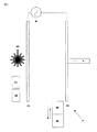
図1に示す機器1はプロセスチャンバー(図示せず)内に収容されている。負プラズマ源電極2及び正プラズマ源電極3は出力源4によって接続されている。レーザー5は正プラズマ源3の上方にあり、ラスタースキャニング機構(図示せず)に接続されている。ガスサプライ6は、チャンバーへの予熱されたプロセスガス、たとえば、CH4/H2を供給するためにオン及びオフすることができる。第二のガスサプライ7はプロセスチャンバーへの不活性ガス、たとえば、N2を供給するためにオン及びオフすることができる。不活性ガスはマトリックス材料の融点温度又はそれよりわずかに低い温度に予熱される。電極2も同様の温度に加熱要素(図示せず)によって加熱される。
Detailed Description of Embodiments The apparatus 1 shown in FIG. 1 is housed in a process chamber (not shown). The negative
加熱されたホッパー8及び冷却されたインクジェットプリンティングヘッド9を輸送機構(図示せず)上に取り付けられ、この輸送機構はホッパー8及びプリンティングヘッド9を図1中、左から右(すなわち、負プラズマ源2の一端から他端)に移動させることができる。輸送機構(図示せず)は負プラズマ源2を上下に移動するために提供される。
A
図1〜10は機器の側面図であり、図面の平面から外れた第3(幅)の寸法を示していない。しかしながら、電極2、3、レーザー5、ホッパー8及びプリンティングヘッド9は機器の幅を横切って延在している。
1 to 10 are side views of the device, and do not show a third (width) dimension outside the plane of the drawing. However, the
図2に示す第1のプロセス工程において、ホッパー(8)はポリエーテルエーテルケトン(PEEK)などのポリマーの粉体で充填されている。ホッパー8は負プラズマ源2を横切って移動され、そしてホッパー8中のディスペンシングオリフィス(示していない)が開放されてポリマー粉体の層10が堆積される。このように、源2はアディティブ層製造プロセスのための床又はプラットフォームとして機能する。オリフィスはその後、閉止される。不活性ガスはポリマーの酸化を抑制する。レーザー5をオンにして、ラスター機構が層10を横切ってビームを走査し、層10を固着させる。レーザービームの加熱効果によって、ポリマー層10が融解する。レーザービームの経路のシャッター(図示していない)を開放しそして閉止し、層10の上を走査している際にビームを選択的に調節する。このため、層10は所望の形状を形成するために要求される領域だけで固着する。より詳細には、所望の三次元形状によって一連のスライスを画定するコンピュータ補助設計(CAD)モデルによってシャッターを開閉する。
In the first process step shown in FIG. 2, the hopper (8) is filled with a polymer powder such as polyetheretherketone (PEEK). The
図3に示す第2のプロセス工程において、プリンティングヘッド9を層10を横切って移動させ、触媒粒子11の配列を堆積させる。プリンティングヘッド9は層10の上にコロイドドロップの配列をスプレーし、高温不活性ガス環境中でコロイドが蒸発し、コロイドドロップ中に懸濁された金属触媒粒子11が堆積される。触媒粒子11は、たとえば、金属であり、好ましくは、遷移金属、Fe、Ni又はCo又はその合金であってよく、コロイド液体は、たとえば、アルコール、水、油又はその混合物であることができる。流体をベースとする冷却装置(図示せず)はプリンティングヘッド9及びプリント流体を含有するリザーバー(図示せず)を冷却し、流体がプリントされる前に、コロイド液体が沸騰することを防止する。プリンティングヘッド9のプリンティングオリフィス(ドロップレットのスプレーを吐出する)を層10に十分に近くに配置し、コロイド液体が層10に衝突する前に、悪影響を及ぼして空中に蒸発することのないようにする。
In the second process step shown in FIG. 3, the
触媒粒子11を図3に、例示のために層10の長さに沿って規則的な間隔で示しているが、粒子間の間隔は長さ及び幅の範囲で本質的にランダムである。
Although the
各触媒粒子の直径は、通常、1nm〜1μmの範囲であり、そして触媒粒子は密に充填されていても、又は、間隔が開いていてもよい。 The diameter of each catalyst particle is usually in the range of 1 nm to 1 μm, and the catalyst particles may be closely packed or spaced apart.
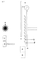
図4に示す第3のプロセス工程において、炭素質のフィード原料をガスサプライ6から導入し、出力源4をオンにし、電極2,3の間にプラズマを生成させる。これにより、電極2、3の間の電磁場の方向に整列された、ナノファイバー12の層の現場成長が行われる。成長機構はBaker (Baker, R.T.K., Barber, M.A., Harris, P.S., Feates, F.S. & Waire, R.J. JJ Catal 26 (1972))によって記載されているとおりである。炭素質ガスは金属触媒粒子の表面上で解離され、炭素がその表面上に吸着され、それが沈殿面に拡散することによって輸送され、触媒粒子を先端に有する炭素フィラメントを形成するということが一般に受け入れられている。この拡散が触媒のバルク中を通って起こるのか又はその表面に沿って起こるのか、そして、拡散が炭素濃縮によって起こるのか又は熱勾配によって起こるのかについての議論は継続してなされている。このように、成長プロセスが完了したときに、ナノファイバー12の「林立」が生じ、各ナノファイバー12の先端には触媒粒子11を有している。
In the third process step shown in FIG. 4, a carbonaceous feedstock is introduced from the
触媒粒子及びプラズマによって、マトリックスの融点よりも低い、比較的に低い温度でのナノファイバーの成長が可能になる。 The catalyst particles and plasma allow nanofiber growth at relatively low temperatures below the melting point of the matrix.
ナノファイバーの直径は、通常、1nm〜1μmの範囲である。このように、「ナノファイバー」として記載しているけれども、ファイバー12の直径は、所望ならば、100nmを超えてもよい。
The diameter of the nanofiber is usually in the range of 1 nm to 1 μm. Thus, although described as “nanofibers”, the diameter of the
いったん、適切な長さのナノファイバー12が成長したら、プラズマ出力源4及びガスサプライ6をオフにし、不活性ガスをパージし、そして図5に示す第4のプロセス工程において、プラットフォーム2を下げ、ホッパー8をナノファイバー12の層に沿って移動させ、ポリマー粉体のさらなる層13を堆積させる。ポリマー粉体のサイズは、通常、ナノファイバー12の直径より3桁大きく、そしてナノファイバー12の間隔より有意に大きい。結果として、図5に示すように、ポリマー粉体層13はナノファイバー12の層の上に配置される。層13は、20〜50μmのポリマー粉体サイズの何倍かの厚さであり、通常、0.2〜0.5mmの大きさである。
Once the appropriate length of
図6に示す第5のプロセス工程において、レーザー5をオンにし、層13を横切ってラスター機構でビームを走査し、それにより、固着された層13’を形成させる。ラスター走査の間に、所望の形状で固着された層13’を形成するために必要とされるとおりにシャッターを開閉する。
In a fifth process step shown in FIG. 6, the
固着されていないポリマー層13の厚さは、図6に示すように、ナノファイバー12の層がその厚さの低部にわたってマトリックスで部分的にのみ含浸され、ナノファイバー12の層の上部は露出されたままとなるように選択される。例として、図5に示す、固着されていない層13の厚さは0.2〜0.5mmの範囲であることができ、そして図6に示す、固着された層13’の厚さは0.1〜0.25mmの範囲であることができる。このため、この場合には、固着されたマトリックス13’の層よりも若干厚いナノファイバー12は0.1mmを超える長さを有し、アスペクト比が100を超える。ファイバー12の長さと、固着された層13’の厚さとの比は図6において約2:1であるが、このことは例示の目的のみであり、実際には、もっとずっと低い程度のオーバーラップ(たとえば、1.05:1の比)が有意な層間強化を提供するために要求される。
The thickness of the
その後、レーザーをオフにし、図2〜6の5つのプロセス工程を繰り返し、一連の層のナノファイバーの層を蓄積させ、ここで、次の層を堆積させる前に、各層がマトリックスで含浸される。 The laser is then turned off and the five process steps of FIGS. 2-6 are repeated to accumulate a series of nanofiber layers, where each layer is impregnated with a matrix before the next layer is deposited. .
このように、第1の繰り返しにおいて、触媒粒子14の第2の層は図7に示すように堆積される。図7において、触媒粒子14はナノファイバー12の配列と交互に規則的な配列で示されている。しかしながら、マトリックス粒子14の分布は長さ及び幅の寸法の両方で本質的にランダムである。
Thus, in the first iteration, a second layer of
図8に示すとおり、ナノファイバー15の第2の層は、その後、触媒粒子14によって触媒されて成長する。ナノファイバー15の第2の層はナノファイバー12の前の層に部分的にオーバーラップされていることに注意されたい。このことは「層間強化」とともに、「層内強化」をもたらす。図8において、垂直に延在しているナノファイバー15で第2の層を示しているが、別の態様において、第2のプラズマ源3はプラットフォーム2に対して移動することができ、それにより、第2の層中のナノファイバーは異なる方向で整列し、たとえば、垂直から45°の鋭角で整列される。所望ならば、ナノファイバーの各々の逐次の層について、電磁場が再指向されうる。要求される位置に、プラットフォーム2に対してプラズマ源電極3を移動させるように輸送機構(図示せず)が提供される。同様に、所望の角度の電磁場が提供されるように、プラットフォーム2を移動させ又は回転させるための機構(図示せず)も提供されうる。
As shown in FIG. 8, the second layer of
図9に示すとおり、負プラズマ源2を再び下げ、そしてポリマー粉体の更なる層16をナノファイバーの層15の上に堆積させる。
As shown in FIG. 9, the
図10に示すとおり、その後、層16をレーザー5によって固着させ、固着された層16’を形成する。
As shown in FIG. 10, the
そのプロセスを、その後、必要に応じて繰り返し、ナノファイバーの各層を、所望の二次元形状及び寸法の断面を形成するように選択的に含浸する。いったん、構造体が形成すると、固着されていない粉体は除去され、所望の三次元形状を有する要素を残す。 The process is then repeated as necessary to selectively impregnate each layer of nanofibers to form a cross-section of the desired two-dimensional shape and dimensions. Once the structure is formed, the unfixed powder is removed, leaving elements with the desired three-dimensional shape.
上記の態様において、触媒粒子11、14のそれぞれの層はファイバーの各層に堆積される。別の態様において、図8に示す重なり合わせた形態の一連の別個のファイバーとして成長するのでなく、末端から末端へと成長する一連のファイバーの層を触媒するように触媒粒子11の層を再使用してもよい。
In the above embodiment, each layer of
場合により、プリンティングヘッド9を選択的に調整して、所望の形状及び/又は充填密度でコロイドドロップの各層を堆積させることもできる。これにより、異なる形状及び/又は充填密度でナノチューブの各層を成長させることができる。場合により、コロイドドロップの充填密度(及び、そのため、ナノチューブの充填密度)は、層間のみならず、層を横切る方向(幅方向及び/又は長さ方向)にも変化させることができる。
Optionally, the
ホッパー8を用いてマトリックス粉体を堆積させる代わりに、マトリックス粉体の層を、ローラーにより又は基材を横切って層を広げる他のフィードシステムにより適用してもよい。
Instead of depositing matrix
図1〜10に示すプロセスにおいて、バルク複合材は一連のナノチューブの層を堆積させることで形成され、ここで、各層は次の層の成長の前に含浸される。 In the process shown in FIGS. 1-10, the bulk composite is formed by depositing a series of nanotube layers, where each layer is impregnated prior to the growth of the next layer.
図11〜13に示す別のプロセスにおいて、単一のナノチューブの層を有するシートを形成するために同一の機器を用いることができる。 In another process shown in FIGS. 11-13, the same equipment can be used to form a sheet having a single nanotube layer.
図11に示すとおり、触媒粒子の層を堆積させた後に、正プラズマ源3を図示した位置に移動させることにより、基材マトリックス層10に対して角度をもってナノチューブの層17を成長させることができる。図12に示すとおり、マトリックス18の層を、その後、堆積させ、図13に示すとおり、ナノチューブの層17を含浸するように該層を固着させる。得られたシートを、その後、プロセスチャンバーから取出し、それを従来の「プリプレグ」と同様に使用しうる。すなわち、複数のこのようなシートを重ね合わせ、ラミネート構造を形成し、ある形状に切断し、そしてモールディングして複合材要素を形成することができる。
As shown in FIG. 11, after depositing a layer of catalyst particles, the
図14〜20は、熱硬化性エポキシ樹脂マトリックス(図1〜13の機器で使用した熱可塑性マトリックスの代わりに)を用いた、複合材の製造のためのアディティブ層(additive layer)製造装置を示す。図14〜20に示す装置は図1の装置のすべての要素を含んでいるが(ホッパー8を除く)、これらの要素は明瞭化のために図14〜20に示していない。 FIGS. 14-20 illustrate an additive layer manufacturing apparatus for manufacturing composites using a thermosetting epoxy resin matrix (instead of the thermoplastic matrix used in the apparatus of FIGS. 1-13). . Although the apparatus shown in FIGS. 14-20 includes all elements of the apparatus of FIG. 1 (except for hopper 8), these elements are not shown in FIGS. 14-20 for clarity.
図14に示す第一のプロセス工程において、プラットフォーム20を液体エポキシ樹脂22の浴21に浸漬させる。図15に示すように、浴21の表面のわずかに上方の位置にプラットフォームを持ち上げ、ここで、樹脂のマウンド22がプラットフォーム20によって支えられている。ドクターブレード(図示せず)をマウンド22を横切ってワイプし、図16に示す樹脂の均一な厚さの層22’を残させる。その後、レーザー(図示せず)をオンにし、層22’を横切って走査し、樹脂を所望の形状で硬化させる。
In the first process step shown in FIG. 14, the
その後、プリンティングヘッド(図示せず)を層22’を横切って移動させ、触媒粒子の列(図示せず)を堆積させる。炭素質原料を、その後、プロセスチャンバー内に導入し、プラズマ源(図示せず)からプラズマを層22に対して角度をもって適用し、電磁場の方向に整列したナノファイバーの層23の成長を生じさせる。45°の角度を図17で示しているが、この角度は、必要ならば、5°まで低くすることができる。
Thereafter, a printing head (not shown) is moved across the layer 22 'to deposit a row of catalyst particles (not shown). A carbonaceous material is then introduced into the process chamber and a plasma is applied at an angle to the
いったん、適切な長さのナノファイバー23が成長したら、プラズマ出力源及びガスサプライをオフにし、チャンバー内の不活性ガスをパージし、そしてプラットフォーム20を図18に示すように下げる。
Once the appropriate length of
プラットフォーム20を、その後、図19に示す浴19の表面のわずかに上方の位置に持ち上げ、ここで、樹脂のマウンド24がナノファイバーの層23を含浸する。ドクターブレードをマウンド23を横切ってワイプし、図20に示す樹脂の均一な厚さの層24’を形成させる。レーザーをオンにし、層24’を横切って走査し、樹脂を所望の形状で硬化させる。図20で層24’はナノファイバーの層23の上方に示されているが、実際には、図6に示す層13’と同様に、層24’は、その硬化後に、厚さの低部でマトリックスを含浸するだけになるように十分に薄くてよいことに注意されたい。これにより、ナノファイバーの次の層と部分的な重なりが生じる。
The
その後、このプロセスを繰り返し、バルク材料を形成する。 The process is then repeated to form the bulk material.
図1〜20は縮尺比に従っておらず、このため、種々の要素の相対寸法は示したものから有意に変更されうることに注意されたい。 It should be noted that FIGS. 1-20 are not to scale, so the relative dimensions of the various elements can be significantly changed from those shown.
本発明は好ましい態様を参照しながら上記に記載してきたが、添付の特許請求の範囲に規定される本発明の範囲から逸脱することなく、種々の変更及び修飾がなされうることは理解されるべきである。 Although the invention has been described above with reference to preferred embodiments, it should be understood that various changes and modifications can be made without departing from the scope of the invention as defined in the appended claims. It is.
本発明は好ましい態様を参照しながら上記に記載してきたが、添付の特許請求の範囲に規定される本発明の範囲から逸脱することなく、種々の変更及び修飾がなされうることは理解されるべきである。
(態様)
(態様1)
強化材の層を成長させること、
前記層をマトリックスで含浸すること、及び、
前記強化材の層の成長の間に前記強化材の層に対して鋭角に電磁場を印加することで前記強化材の層を整列させること、
を含む、複合材の製造方法。
(態様2)
前記層の成長の間にプラズマを形成することをさらに含む、態様1記載の方法。
(態様3)
前記強化材の層の成長を触媒する触媒粒子の層を形成することをさらに含む、態様1又は2記載の方法。
(態様4)
触媒粒子の層を横切って触媒粒子の充填密度が変化している、触媒粒子の層を形成することをさらに含む、態様3記載の方法。
(態様5)
強化材の層を成長させること、
前記層をマトリックスで含浸すること、及び、
懸濁液又は溶液中に触媒粒子を含む液体のドロップレットを表面上にスプレーすることで、前記強化材の層の成長を触媒するための触媒粒子の層を形成させること、
を含む、複合材の製造方法。
(態様6)
前記液体はコロイド懸濁液中に触媒粒子を含む、態様5記載の方法。
(態様7)
前記強化材の層を横切って充填密度が変化している強化材の層を成長させることをさらに含む、態様1〜6のいずれか1項記載の方法。
(態様8)
態様1〜7のいずれか1項記載の方法によって2層以上の複合材シートを製造すること、
前記シートを積層してラミネート構造を形成すること、及び、
前記ラミネート構造をモールディングすること、
を含む、態様1〜7のいずれか1項記載の方法。
(態様9)
強化材の層を成長させそして該層をマトリックスで含浸することによって各シートを製造する、2層以上の複合材シートを製造すること、
前記シートを積層してラミネート構造を形成すること、及び、
前記ラミネート構造をモールディングすること、
を含む、複合材の製造方法。
(態様10)
含浸の間にマトリックスを加熱することをさらに含む、態様1〜9のいずれか1項記載の方法。
(態様11)
前記マトリックスをレーザービームによって加熱する、態様10記載の方法。
(態様12)
前記強化材の層の上にマトリックス材料の層を堆積させ、そしてマトリックス材料の層の少なくとも一部を加熱することで前記強化材の層が含浸される、態様10又は11記載の方法。
(態様13)
前記マトリックス材料の層は粉体である、態様12記載の方法。
(態様14)
前記強化材の層は毛細管作用によって含浸される、態様1〜13のいずれか1項記載の方法。
(態様15)
前記マトリックスはポリマーである、態様1〜14のいずれか1項記載の方法。
(態様16)
前記マトリックスは熱可塑性である、態様1〜15のいずれか1項記載の方法。
(態様17)
前記マトリックスは熱硬化性である、態様1〜16のいずれか1項記載の方法。
(態様18)
前記強化材の層はアスペクト比が100を超える強化材要素を含む、態様1〜17のいずれか1項記載の方法。
(態様19)
前記強化材の層は直径が100nm未満である強化材要素を含む、態様1〜18のいずれか1項記載の方法。
(態様20)
前記強化材の層はカーボンファイバーを含む、態様1〜19のいずれか1項記載の方法。
(態様21)
態様1〜20のいずれか1項記載の方法により製造された、複合材。
(態様22)
強化材の層を成長させるための装置、
前記層に鋭角で電磁場を印加するための電極、及び、
前記層にマトリックス材料を塗布し、各層をマトリックス材料で含浸するための含浸装置、
を含む、複合材を製造するための機器。
(態様23)
現場(in-situ)で強化材の層を成長させるための装置、
触媒粒子を含む液体のドロップレットを、プリンティングオリフィスから表面上にスプレーすることで、前記強化材の層の成長を触媒するための触媒粒子の層を形成させるためのプリンティングヘッド、及び、
前記層にマトリックス材料を塗布し、該層をマトリックス材料で含浸するための含浸装置、
を含む、複合材を製造するための機器。
Although the invention has been described above with reference to preferred embodiments, it should be understood that various changes and modifications can be made without departing from the scope of the invention as defined in the appended claims. It is.
(Aspect)
(Aspect 1)
Growing a layer of reinforcement,
Impregnating the layer with a matrix; and
Aligning the reinforcement layer by applying an electromagnetic field at an acute angle to the reinforcement layer during growth of the reinforcement layer;
The manufacturing method of the composite material containing this.
(Aspect 2)
The method of embodiment 1, further comprising forming a plasma during growth of the layer.
(Aspect 3)
The method of
(Aspect 4)
The method of
(Aspect 5)
Growing a layer of reinforcement,
Impregnating the layer with a matrix; and
Spraying liquid droplets containing catalyst particles in suspension or solution onto the surface to form a layer of catalyst particles to catalyze the growth of the layer of reinforcement;
The manufacturing method of the composite material containing this.
(Aspect 6)
The method of
(Aspect 7)
The method of any one of aspects 1-6, further comprising growing a layer of reinforcement having a varying packing density across the layer of reinforcement.
(Aspect 8)
Producing a composite sheet of two or more layers by the method according to any one of aspects 1 to 7,
Laminating the sheets to form a laminate structure; and
Molding the laminate structure;
The method according to any one of aspects 1 to 7, comprising:
(Aspect 9)
Producing two or more composite sheets, wherein each sheet is produced by growing a layer of reinforcement and impregnating the layer with a matrix;
Laminating the sheets to form a laminate structure; and
Molding the laminate structure;
The manufacturing method of the composite material containing this.
(Aspect 10)
10. A method according to any one of aspects 1-9, further comprising heating the matrix during impregnation.
(Aspect 11)
The method of
(Aspect 12)
12. The method of
(Aspect 13)
(Aspect 14)
14. A method according to any one of aspects 1 to 13, wherein the reinforcement layer is impregnated by capillary action.
(Aspect 15)
15. A method according to any one of aspects 1 to 14, wherein the matrix is a polymer.
(Aspect 16)
16. A method according to any one of aspects 1-15, wherein the matrix is thermoplastic.
(Aspect 17)
The method according to any one of aspects 1 to 16, wherein the matrix is thermosetting.
(Aspect 18)
18. A method according to any one of aspects 1 to 17, wherein the reinforcement layer comprises reinforcement elements having an aspect ratio greater than 100.
(Aspect 19)
19. A method according to any one of aspects 1-18, wherein the reinforcement layer comprises a reinforcement element having a diameter of less than 100 nm.
(Aspect 20)
20. A method according to any one of aspects 1-19, wherein the reinforcement layer comprises carbon fibers.
(Aspect 21)
21. A composite material produced by the method according to any one of aspects 1 to 20.
(Aspect 22)
An apparatus for growing a layer of reinforcement,
An electrode for applying an electromagnetic field at an acute angle to the layer; and
An impregnation apparatus for applying a matrix material to the layers and impregnating each layer with the matrix material;
Equipment for manufacturing composite materials, including
(Aspect 23)
Equipment for growing a layer of reinforcement in-situ,
A printing head for forming a layer of catalyst particles to catalyze the growth of the layer of reinforcing material by spraying liquid droplets containing catalyst particles onto the surface from a printing orifice; and
An impregnation apparatus for applying a matrix material to the layer and impregnating the layer with the matrix material;
Equipment for manufacturing composite materials, including
Claims (23)
前記層をマトリックスで含浸すること、及び、
前記強化材の層の成長の間に前記強化材の層に対して鋭角に電磁場を印加することで前記強化材の層を整列させること、
を含む、複合材の製造方法。 Growing a layer of reinforcement,
Impregnating the layer with a matrix; and
Aligning the reinforcement layer by applying an electromagnetic field at an acute angle to the reinforcement layer during growth of the reinforcement layer;
The manufacturing method of the composite material containing this.
前記層をマトリックスで含浸すること、及び、
懸濁液又は溶液中に触媒粒子を含む液体のドロップレットを表面上にスプレーすることで、前記強化材の層の成長を触媒するための触媒粒子の層を形成させること、
を含む、複合材の製造方法。 Growing a layer of reinforcement,
Impregnating the layer with a matrix; and
Spraying liquid droplets containing catalyst particles in suspension or solution onto the surface to form a layer of catalyst particles to catalyze the growth of the layer of reinforcement;
The manufacturing method of the composite material containing this.
前記シートを積層してラミネート構造を形成すること、及び、
前記ラミネート構造をモールディングすること、
を含む、請求項1〜7のいずれか1項記載の方法。 Producing a composite sheet of two or more layers by the method according to any one of claims 1 to 7,
Laminating the sheets to form a laminate structure; and
Molding the laminate structure;
The method according to claim 1, comprising:
前記シートを積層してラミネート構造を形成すること、及び、
前記ラミネート構造をモールディングすること、
を含む、複合材の製造方法。 Producing two or more composite sheets, wherein each sheet is produced by growing a layer of reinforcement and impregnating the layer with a matrix;
Laminating the sheets to form a laminate structure; and
Molding the laminate structure;
The manufacturing method of the composite material containing this.
前記層に鋭角で電磁場を印加するための電極、及び、
前記層にマトリックス材料を塗布し、各層をマトリックス材料で含浸するための含浸装置、
を含む、複合材を製造するための機器。 An apparatus for growing a layer of reinforcement,
An electrode for applying an electromagnetic field at an acute angle to the layer; and
An impregnation apparatus for applying a matrix material to the layers and impregnating each layer with the matrix material;
Equipment for manufacturing composite materials, including
触媒粒子を含む液体のドロップレットを、プリンティングオリフィスから表面上にスプレーすることで、前記強化材の層の成長を触媒するための触媒粒子の層を形成させるためのプリンティングヘッド、及び、
前記層にマトリックス材料を塗布し、該層をマトリックス材料で含浸するための含浸装置、
を含む、複合材を製造するための機器。 Equipment for growing a layer of reinforcement in-situ,
A printing head for forming a layer of catalyst particles to catalyze the growth of the layer of reinforcing material by spraying liquid droplets containing catalyst particles onto the surface from a printing orifice; and
An impregnation apparatus for applying a matrix material to the layer and impregnating the layer with the matrix material;
Equipment for manufacturing composite materials, including
Applications Claiming Priority (4)
| Application Number | Priority Date | Filing Date | Title |
|---|---|---|---|
| US82456506P | 2006-09-05 | 2006-09-05 | |
| US60/824,565 | 2006-09-05 | ||
| GB0617460.1 | 2006-09-05 | ||
| GBGB0617460.1A GB0617460D0 (en) | 2006-09-05 | 2006-09-05 | Method of manufacturing composite material |
Related Parent Applications (1)
| Application Number | Title | Priority Date | Filing Date |
|---|---|---|---|
| JP2009527212A Division JP5587602B2 (en) | 2006-09-05 | 2007-08-29 | Manufacturing method of composite material |
Publications (2)
| Publication Number | Publication Date |
|---|---|
| JP2013144809A true JP2013144809A (en) | 2013-07-25 |
| JP5588038B2 JP5588038B2 (en) | 2014-09-10 |
Family
ID=37232391
Family Applications (2)
| Application Number | Title | Priority Date | Filing Date |
|---|---|---|---|
| JP2009527212A Expired - Fee Related JP5587602B2 (en) | 2006-09-05 | 2007-08-29 | Manufacturing method of composite material |
| JP2013068680A Expired - Fee Related JP5588038B2 (en) | 2006-09-05 | 2013-03-28 | Manufacturing method of composite material |
Family Applications Before (1)
| Application Number | Title | Priority Date | Filing Date |
|---|---|---|---|
| JP2009527212A Expired - Fee Related JP5587602B2 (en) | 2006-09-05 | 2007-08-29 | Manufacturing method of composite material |
Country Status (10)
| Country | Link |
|---|---|
| US (1) | US20100004388A1 (en) |
| EP (2) | EP2061644B1 (en) |
| JP (2) | JP5587602B2 (en) |
| CN (2) | CN101511570B (en) |
| AT (1) | ATE530332T1 (en) |
| BR (1) | BRPI0716167A2 (en) |
| CA (1) | CA2661746C (en) |
| GB (1) | GB0617460D0 (en) |
| RU (1) | RU2448832C2 (en) |
| WO (1) | WO2008029179A2 (en) |
Families Citing this family (9)
| Publication number | Priority date | Publication date | Assignee | Title |
|---|---|---|---|---|
| GB0715164D0 (en) * | 2007-08-06 | 2007-09-12 | Airbus Uk Ltd | Method and apparatus for manufacturing a composite material |
| GB0715990D0 (en) * | 2007-08-16 | 2007-09-26 | Airbus Uk Ltd | Method and apparatus for manufacturing a component from a composite material |
| RU2459888C2 (en) * | 2010-11-30 | 2012-08-27 | Открытое акционерное общество "Композит" (ОАО "Композит") | Method of making shell structures |
| RU2478562C1 (en) * | 2011-08-11 | 2013-04-10 | Государственное образовательное учреждение высшего профессионального образования "Владимирский государственный университет имени Александра Григорьевича и Николая Григорьевича Столетовых" (ВлГУ) | Method of obtaining fibres in electric uniform field |
| RU2567283C2 (en) * | 2013-11-18 | 2015-11-10 | Александр Григорьевич Григорьянц | Method and device for producing of carbon nanotubes |
| RU2641921C2 (en) * | 2016-07-14 | 2018-01-23 | Федеральное государственное бюджетное образовательное учреждение высшего образования "Башкирский государственный университет" | Electrically conductive metal-filled polymer compound for 3d-printing (versions) |
| RU2641134C1 (en) * | 2016-07-14 | 2018-01-16 | Федеральное государственное бюджетное образовательное учреждение высшего образования "Башкирский государственный университет" | Electrically conductive metal-filled polymer compound for 3d-printing (versions) |
| US11732382B2 (en) * | 2016-10-26 | 2023-08-22 | Purdue Research Foundation | Roll-to-roll manufacturing machines and methods for producing nanostructure-containing polymer films |
| DE102018102061B3 (en) * | 2018-01-30 | 2019-03-14 | Brandenburgische Technische Universität Cottbus-Senftenberg | Extrusion apparatus and method for producing carbon fiber reinforced plastic semi-finished products |
Citations (4)
| Publication number | Priority date | Publication date | Assignee | Title |
|---|---|---|---|---|
| JP2002514694A (en) * | 1998-05-13 | 2002-05-21 | アプライド・サイエンシズ・インコーポレーテッド | Plasma catalysis for obtaining carbon nanofibers |
| WO2005102924A1 (en) * | 2004-04-19 | 2005-11-03 | Japan Science And Technology Agency | Carbon-based fine structure group, aggregate of carbon based fine structures, use thereof and method for preparation thereof |
| JP2006069165A (en) * | 2004-09-06 | 2006-03-16 | Japan Science & Technology Agency | Carbon nanotube composite sheet and its production method |
| JP2008544939A (en) * | 2005-06-28 | 2008-12-11 | ザ ボード オブ リージェンツ オブ ザ ユニバーシティ オブ オクラホマ | Method for growing and collecting carbon nanotubes |
Family Cites Families (35)
| Publication number | Priority date | Publication date | Assignee | Title |
|---|---|---|---|---|
| US4560603A (en) * | 1983-10-27 | 1985-12-24 | Ltv Aerospace And Defense Company | Composite matrix with oriented whiskers |
| RU2048295C1 (en) * | 1992-01-24 | 1995-11-20 | Юрий Иванович Кадун | Method for making laminated article from composite material |
| US5837081A (en) * | 1993-04-07 | 1998-11-17 | Applied Sciences, Inc. | Method for making a carbon-carbon composite |
| KR20010074667A (en) * | 1998-06-19 | 2001-08-08 | 추후보정 | Free-standing and aligned carbon nanotubes and synthesis thereof |
| US6265466B1 (en) * | 1999-02-12 | 2001-07-24 | Eikos, Inc. | Electromagnetic shielding composite comprising nanotubes |
| AUPP976499A0 (en) * | 1999-04-16 | 1999-05-06 | Commonwealth Scientific And Industrial Research Organisation | Multilayer carbon nanotube films |
| US6214276B1 (en) * | 1999-05-18 | 2001-04-10 | Creo Srl | Method of forming objects from thermosensitive composition |
| EP1059266A3 (en) * | 1999-06-11 | 2000-12-20 | Iljin Nanotech Co., Ltd. | Mass synthesis method of high purity carbon nanotubes vertically aligned over large-size substrate using thermal chemical vapor deposition |
| CN101104514A (en) * | 1999-10-27 | 2008-01-16 | 威廉马歇莱思大学 | Macroscopic ordered assembly of carbon nanotubes |
| US6923946B2 (en) * | 1999-11-26 | 2005-08-02 | Ut-Battelle, Llc | Condensed phase conversion and growth of nanorods instead of from vapor |
| US6495116B1 (en) * | 2000-04-10 | 2002-12-17 | Lockheed Martin Corporation | Net shape manufacturing using carbon nanotubes |
| US6749712B2 (en) * | 2000-08-23 | 2004-06-15 | Nano Dynamics, Inc. | Method of utilizing sol-gel processing in the production of a macroscopic two or three dimensionally ordered array of single wall nonotubes (SWNTs) |
| US6428890B1 (en) * | 2001-06-07 | 2002-08-06 | National Cheng Kung University | Polymer matrix composite and method for making the same |
| US6921462B2 (en) * | 2001-12-17 | 2005-07-26 | Intel Corporation | Method and apparatus for producing aligned carbon nanotube thermal interface structure |
| US6746768B2 (en) * | 2001-12-26 | 2004-06-08 | Advanced Energy Technology Inc. | Thermal interface material |
| US6913794B2 (en) * | 2002-01-14 | 2005-07-05 | Coherent, Inc. | Diode-laser curing of liquid epoxide encapsulants |
| JP3962862B2 (en) * | 2002-02-27 | 2007-08-22 | 日立造船株式会社 | Conductive material using carbon nanotube and method for producing the same |
| DE10318663A1 (en) * | 2002-04-26 | 2004-01-08 | Sumitomo Chemical Co., Ltd. | Fiber-reinforced polyolefin resin composite and molded part obtained therefrom |
| FR2844510B1 (en) * | 2002-09-12 | 2006-06-16 | Snecma Propulsion Solide | THREE-DIMENSIONAL FIBROUS STRUCTURE OF REFRACTORY FIBERS, PROCESS FOR THE PRODUCTION THEREOF AND APPLICATION TO THERMOSTRUCTURAL COMPOSITE MATERIALS |
| US20040071951A1 (en) * | 2002-09-30 | 2004-04-15 | Sungho Jin | Ultra-high-density information storage media and methods for making the same |
| US20030154865A1 (en) * | 2002-10-16 | 2003-08-21 | Zornes David A. | Nano coupling magnetoadsorbent |
| US6841003B2 (en) * | 2002-11-22 | 2005-01-11 | Cdream Display Corporation | Method for forming carbon nanotubes with intermediate purification steps |
| JP2004298357A (en) * | 2003-03-31 | 2004-10-28 | Mizuno Technics Kk | Golf shaft |
| US7118941B2 (en) * | 2003-06-25 | 2006-10-10 | Intel Corporation | Method of fabricating a composite carbon nanotube thermal interface device |
| JP2005041835A (en) * | 2003-07-24 | 2005-02-17 | Fuji Xerox Co Ltd | Carbon nanotube structure, method for producing the same, carbon nanotube transfer and solution |
| US7091120B2 (en) * | 2003-08-04 | 2006-08-15 | Nanosys, Inc. | System and process for producing nanowire composites and electronic substrates therefrom |
| US20050116336A1 (en) * | 2003-09-16 | 2005-06-02 | Koila, Inc. | Nano-composite materials for thermal management applications |
| US20050061496A1 (en) * | 2003-09-24 | 2005-03-24 | Matabayas James Christopher | Thermal interface material with aligned carbon nanotubes |
| US7181836B2 (en) * | 2003-12-19 | 2007-02-27 | General Electric Company | Method for making an electrode structure |
| US20050169831A1 (en) * | 2004-02-04 | 2005-08-04 | Montgomery Stephen W. | Three-dimensional nanotube structure |
| CN100383213C (en) * | 2004-04-02 | 2008-04-23 | 清华大学 | Thermal interface material and its manufacturing method |
| US20050279274A1 (en) * | 2004-04-30 | 2005-12-22 | Chunming Niu | Systems and methods for nanowire growth and manufacturing |
| US20060025515A1 (en) * | 2004-07-27 | 2006-02-02 | Mainstream Engineering Corp. | Nanotube composites and methods for producing |
| US7129097B2 (en) * | 2004-07-29 | 2006-10-31 | International Business Machines Corporation | Integrated circuit chip utilizing oriented carbon nanotube conductive layers |
| US20060083927A1 (en) * | 2004-10-15 | 2006-04-20 | Zyvex Corporation | Thermal interface incorporating nanotubes |
-
2006
- 2006-09-05 GB GBGB0617460.1A patent/GB0617460D0/en not_active Ceased
-
2007
- 2007-08-29 CN CN200780032906XA patent/CN101511570B/en not_active Expired - Fee Related
- 2007-08-29 RU RU2009110970/05A patent/RU2448832C2/en not_active IP Right Cessation
- 2007-08-29 AT AT07789385T patent/ATE530332T1/en not_active IP Right Cessation
- 2007-08-29 EP EP07789385A patent/EP2061644B1/en not_active Not-in-force
- 2007-08-29 CA CA2661746A patent/CA2661746C/en not_active Expired - Fee Related
- 2007-08-29 WO PCT/GB2007/050510 patent/WO2008029179A2/en active Application Filing
- 2007-08-29 US US12/439,267 patent/US20100004388A1/en not_active Abandoned
- 2007-08-29 CN CN2012102875795A patent/CN102774016A/en active Pending
- 2007-08-29 BR BRPI0716167-0A2A patent/BRPI0716167A2/en not_active IP Right Cessation
- 2007-08-29 JP JP2009527212A patent/JP5587602B2/en not_active Expired - Fee Related
- 2007-08-29 EP EP11185691A patent/EP2409827B1/en not_active Not-in-force
-
2013
- 2013-03-28 JP JP2013068680A patent/JP5588038B2/en not_active Expired - Fee Related
Patent Citations (4)
| Publication number | Priority date | Publication date | Assignee | Title |
|---|---|---|---|---|
| JP2002514694A (en) * | 1998-05-13 | 2002-05-21 | アプライド・サイエンシズ・インコーポレーテッド | Plasma catalysis for obtaining carbon nanofibers |
| WO2005102924A1 (en) * | 2004-04-19 | 2005-11-03 | Japan Science And Technology Agency | Carbon-based fine structure group, aggregate of carbon based fine structures, use thereof and method for preparation thereof |
| JP2006069165A (en) * | 2004-09-06 | 2006-03-16 | Japan Science & Technology Agency | Carbon nanotube composite sheet and its production method |
| JP2008544939A (en) * | 2005-06-28 | 2008-12-11 | ザ ボード オブ リージェンツ オブ ザ ユニバーシティ オブ オクラホマ | Method for growing and collecting carbon nanotubes |
Also Published As
| Publication number | Publication date |
|---|---|
| EP2409827B1 (en) | 2012-11-28 |
| BRPI0716167A2 (en) | 2013-09-17 |
| WO2008029179A2 (en) | 2008-03-13 |
| CN102774016A (en) | 2012-11-14 |
| EP2409827A1 (en) | 2012-01-25 |
| CA2661746A1 (en) | 2008-03-13 |
| JP5588038B2 (en) | 2014-09-10 |
| US20100004388A1 (en) | 2010-01-07 |
| CN101511570B (en) | 2012-10-03 |
| EP2061644A2 (en) | 2009-05-27 |
| GB0617460D0 (en) | 2006-10-18 |
| CA2661746C (en) | 2015-03-31 |
| CN101511570A (en) | 2009-08-19 |
| RU2448832C2 (en) | 2012-04-27 |
| JP5587602B2 (en) | 2014-09-10 |
| WO2008029179A3 (en) | 2008-04-24 |
| JP2010502808A (en) | 2010-01-28 |
| RU2009110970A (en) | 2010-10-20 |
| EP2061644B1 (en) | 2011-10-26 |
| ATE530332T1 (en) | 2011-11-15 |
Similar Documents
| Publication | Publication Date | Title |
|---|---|---|
| JP5021744B2 (en) | Method of manufacturing composite material by growth of reinforcing material layer and related equipment | |
| JP5588038B2 (en) | Manufacturing method of composite material | |
| CA2695847C (en) | Method and apparatus for manufacturing a composite material | |
| RU2447994C2 (en) | Method of producing composite material by growing reinforcing layers and device to this end | |
| US10399322B2 (en) | Three-dimensional printing using carbon nanostructures | |
| US20120280430A1 (en) | Composite tooling containing carbon nanotubes and production of parts therefrom | |
| US11897194B2 (en) | Method and system for dynamic capillary-driven additive manufacturing of continuous fiber composite | |
| EP2683542B1 (en) | Method of manufacturing a composite material and composite material |
Legal Events
| Date | Code | Title | Description |
|---|---|---|---|
| A131 | Notification of reasons for refusal |
Free format text: JAPANESE INTERMEDIATE CODE: A131 Effective date: 20131203 |
|
| A521 | Request for written amendment filed |
Free format text: JAPANESE INTERMEDIATE CODE: A523 Effective date: 20140228 |
|
| TRDD | Decision of grant or rejection written | ||
| A01 | Written decision to grant a patent or to grant a registration (utility model) |
Free format text: JAPANESE INTERMEDIATE CODE: A01 Effective date: 20140624 |
|
| A61 | First payment of annual fees (during grant procedure) |
Free format text: JAPANESE INTERMEDIATE CODE: A61 Effective date: 20140724 |
|
| R150 | Certificate of patent or registration of utility model |
Ref document number: 5588038 Country of ref document: JP Free format text: JAPANESE INTERMEDIATE CODE: R150 |
|
| LAPS | Cancellation because of no payment of annual fees |