EP2061140A2 - Synchronous hybrid electric machine - Google Patents
Synchronous hybrid electric machine Download PDFInfo
- Publication number
- EP2061140A2 EP2061140A2 EP09001533A EP09001533A EP2061140A2 EP 2061140 A2 EP2061140 A2 EP 2061140A2 EP 09001533 A EP09001533 A EP 09001533A EP 09001533 A EP09001533 A EP 09001533A EP 2061140 A2 EP2061140 A2 EP 2061140A2
- Authority
- EP
- European Patent Office
- Prior art keywords
- stator
- rotor
- motor
- electric machine
- ring
- Prior art date
- Legal status (The legal status is an assumption and is not a legal conclusion. Google has not performed a legal analysis and makes no representation as to the accuracy of the status listed.)
- Withdrawn
Links
Images


Classifications
-
- H—ELECTRICITY
- H02—GENERATION; CONVERSION OR DISTRIBUTION OF ELECTRIC POWER
- H02K—DYNAMO-ELECTRIC MACHINES
- H02K21/00—Synchronous motors having permanent magnets; Synchronous generators having permanent magnets
- H02K21/12—Synchronous motors having permanent magnets; Synchronous generators having permanent magnets with stationary armatures and rotating magnets
- H02K21/125—Synchronous motors having permanent magnets; Synchronous generators having permanent magnets with stationary armatures and rotating magnets having an annular armature coil
-
- H—ELECTRICITY
- H02—GENERATION; CONVERSION OR DISTRIBUTION OF ELECTRIC POWER
- H02K—DYNAMO-ELECTRIC MACHINES
- H02K11/00—Structural association of dynamo-electric machines with electric components or with devices for shielding, monitoring or protection
- H02K11/01—Structural association of dynamo-electric machines with electric components or with devices for shielding, monitoring or protection for shielding from electromagnetic fields, i.e. structural association with shields
- H02K11/014—Shields associated with stationary parts, e.g. stator cores
- H02K11/0141—Shields associated with casings, enclosures or brackets
-
- H—ELECTRICITY
- H02—GENERATION; CONVERSION OR DISTRIBUTION OF ELECTRIC POWER
- H02K—DYNAMO-ELECTRIC MACHINES
- H02K5/00—Casings; Enclosures; Supports
- H02K5/04—Casings or enclosures characterised by the shape, form or construction thereof
- H02K5/16—Means for supporting bearings, e.g. insulating supports or means for fitting bearings in the bearing-shields
- H02K5/173—Means for supporting bearings, e.g. insulating supports or means for fitting bearings in the bearing-shields using bearings with rolling contact, e.g. ball bearings
- H02K5/1732—Means for supporting bearings, e.g. insulating supports or means for fitting bearings in the bearing-shields using bearings with rolling contact, e.g. ball bearings radially supporting the rotary shaft at both ends of the rotor
-
- H—ELECTRICITY
- H02—GENERATION; CONVERSION OR DISTRIBUTION OF ELECTRIC POWER
- H02K—DYNAMO-ELECTRIC MACHINES
- H02K1/00—Details of the magnetic circuit
- H02K1/06—Details of the magnetic circuit characterised by the shape, form or construction
- H02K1/12—Stationary parts of the magnetic circuit
- H02K1/14—Stator cores with salient poles
- H02K1/141—Stator cores with salient poles consisting of C-shaped cores
-
- H—ELECTRICITY
- H02—GENERATION; CONVERSION OR DISTRIBUTION OF ELECTRIC POWER
- H02K—DYNAMO-ELECTRIC MACHINES
- H02K1/00—Details of the magnetic circuit
- H02K1/06—Details of the magnetic circuit characterised by the shape, form or construction
- H02K1/12—Stationary parts of the magnetic circuit
- H02K1/14—Stator cores with salient poles
- H02K1/145—Stator cores with salient poles having an annular coil, e.g. of the claw-pole type
-
- H—ELECTRICITY
- H02—GENERATION; CONVERSION OR DISTRIBUTION OF ELECTRIC POWER
- H02K—DYNAMO-ELECTRIC MACHINES
- H02K2201/00—Specific aspects not provided for in the other groups of this subclass relating to the magnetic circuits
- H02K2201/12—Transversal flux machines
Definitions
- the present invention also pertains to a synchronous hybrid electric machine.
- the present relates to a synchronous hybrid electric machine with transverse magnetic flux whose structure is such that it minimizes eddy current losses in the motor and thus, it provides improved energy efficiency as compared to conventional motors with similar construction.
- Hybrid electric machines are a subclass of synchronous electric machines. In construction they are similar to stepper motors with in-built permanent magnets that increase magnetic filed density in the air gap, but unlikely the stepper motors, the hybrid electric machines are usually fed by sinusoidal electric currents.
- a motor of this construction is described in the European patent 0544200 , wherein it has in each phase of the stator only one coil which is coaxial with the motor axis and magnetises simultaneously a circular array of stator yokes which encircle the stator coil. Similarly, in each phase of the rotor this motor also has only one permanent magnet, which is also coaxial with the motor axis and is placed between two iron rings with salient poles on inner and outer circumference. The number of salient poles on each circumference equals the number of stator yokes.
- the machine according to the above-described constructional solution has high torque per weight and good energy efficiency. This is advantageous especially at low motor speed when efficiency of other electric motors is usually low.
- One partial solution could be replacement of metal as the building material in passive parts (especially in rotor and stator armature) with electrically insulating materials (like ceramics or plastic materials), but usually such solutions are either too expensive (for ceramics) or mechanically inadequate (for plastics).
- An object of the present invention is therefore to find such a constructional solution of stator armature, rotor armature, and iron rings of the rotor, that induction of undesirable eddy currents within these parts is strongly damped or impeded.
- the above object has been successfully achieved by a hybrid synchronous machine with transverse magnetic flux comprising a rotor and a stator, the rotor armature comprising a rotor assembly having cogged iron rings, and the rotor assembly having cross-cut insulating gaps.
- the hybrid synchronous machine also has at least one massive copper ring in close vicinity of the active motor parts.
- a hybrid synchronous electric machine with transverse magnetic flux of the present invention is characterized in that it comprises: a rotor and a stator; the rotor comprises at least one rotor assembly (13) of cogged iron rings (14, 15); and each assembly has at least one cross-cut insulating gap (22).
- the hybrid synchronous electric machine with transverse magnetic flux of the present invention is characterized in that it comprises: a rotor, a stator, and a massive conducting ring (12); and the conducting ring (12) is coaxial with the motor axis (5) and in close vicinity of the active area of the motor.
- the conducting ring (12) may be made of copper.
- the conducting ring (12) may be part of the rotor armature (11).
- cogged iron rings (14, 15) of the assembly (13) are electrically insulated from the supporting conducting ring (12).
- the stator may be assembled by at least one circular array (2) constituted by U-shaped stator yokes (3b or 3c) spaced closely together, each yoke (3b or 3c) asymmetrically consisting of two identical, but mutually overturned iron parts (23b, 24b or 23c, 24c).
- the hybrid synchronous motor according the present invention has low eddy current losses because eddy currents in cogged iron rings are impeded by cross-cut insulating gaps in these same iron rings, while eddy currents in all passive parts of the motor (like rotor armature, stator armature, and ball bearings) are negligible since the current induced in the copper ring neutralizes all the dissipated magnetic flux outside the active area of the motor. Further, this motor is very compact, strong and mechanically stable, despite low eddy current losses.
- the subject-matter of the invention also comprises a synchronous hybrid electric machine as set out in the following numbered paragraphs:
- a first embodiment (example A) of a two-phase synchronous hybrid electric machine with transverse magnetic flux according to the invention is shown.
- a circular array (2) of U-shaped stator yokes (3) which encircle the stator winding (4) of the corresponding phase.
- the windings (4) are coaxial with the motor axis (5).
- Stator yokes (3) with salient poles (6, 7) are more precisely shown in Fig. 3 .
- the yokes may be of bulk iron but it is better that the yokes (3) are lamination packages, as it is shown in Figs. 1 and 3 .
- the ferromagnetic cogged rings (14, 15) can be lamination packages, just like the stator yokes (3). (For the sake of clarity, these lamellae are not shown in Fig. 2 ).
- the magnetized disk (20) is magnetized in the axial direction so as to produce a magnetic flux that can be directed either from the cogged ring (14) to the cogged ring (15) or in the opposite direction.
- the cogged rings (14, 15) and the magnetized disk (20) can be held together by means of screws (21), as shown more precisely in Fig. 2 (A) .
- the same screws (21) can be used to fasten the rotor assembly (13) to the copper ring (12).
- the cogged rings (14, 15) are electrically insulated from the supporting copper ring (12), this can be achieved for instance by applying a thin ceramic layer onto the stems of the screws (21) and onto the surface of the copper ring (12).
- the cogged rings (14, 15) have in at least one place a narrow insulating gap (22) to prevent free circulation of circular eddy currents, as is shown in Fig. 2(A) .
- the cogged rotor rings (14, 15) and the stator yokes (3) are in the magnetic juncture; in each phase the number of stator yokes (3) is equal to the number of rotor poles (16, 17, 18, 19).
- the cogged rings (14, 15) in the assembly (13) of variant A are placed such that their outer poles (18, 19) are mutually shifted for one half of pole division, as shown in Fig. 2(A) (example A). The same holds for the inner poles (16, 17).
- stator poles attract the rotor poles towards a position which is shifted by 1/2 of the pole's division with regard to the position at the chosen moment, so that in the end position of observation the stator pole (6) coincides with the rotor pole (16) of the cogged ring (14), and the stator pole (7) coincides with the rotor pole (19) of the cogged ring (15).
- the direction of current in the winding (4) inverts. This causes the rotor to move forwards, so that it reassumes the initially observed position of mutual covering of the rotor and stator poles.
- the rotation of rotor is enabled, while the change itself can be achieved by electronic commutation.
- the solution according to the present invention applies in most of the cases, except in such cases when the nominal motor speed is so low that we cannot get Q smaller than unity.
- the copper ring (12) is not used, and the rotor armature (11) can extend into the area near the active parts of the motor. Then it is good that the armatures (11) and (1) are then made of materials with much higher electric resistance ⁇ , since in such cases we have no other means to reduce eddy currents in the passive parts of the motor.
- the ring (12) forms an attached part of the rotor armature (11), so instead of pure copper (oxygen free & high conductivity copper) which is too soft for mechanical applications, one can make a compromise by use of copper with small addition of alloying metals. In this way one can quite easily and sufficiently increase the mechanical stiffness without excessively increasing the specific resistance ⁇ .
- the problem of eddy current losses has been successfully solved by a hybrid synchronous machine with transverse magnetic flux, the rotor armature (11) comprising of at least one massive copper ring (12) in close vicinity of the active motor parts, and the rotor rings (14, 15, 20) having at least one cross-cut insulating gap (22).
- the described solution also improves the compactness of motor. Namely, the cogged iron rings (14, 15) with cross-cut insulating gaps (22) are more flexible than rings without these gaps (22), especially in the case they are lamination packages. Hence, the rotor rings (14, 15, 20) need a firm support, which can be easily provided by the massive copper ring (12).
- FIG. 4 and 5 Another improvement in motor compactness, which is also a matter of the present invention, is shown in Figs. 4 and 5 . Constructions with these improvements are described as examples B and C, which introduce some modifications to the original example A shown in Fig. 3 .
- examples B and C which introduce some modifications to the original example A shown in Fig. 3 .
- the U-shaped stator yokes (3) in the circular array (2) are separated from each other.
- Some additional part e.g., made from plastic material
- this plastic part is no more necessary, since the stator yokes (3b) are not separated among themselves.
- a yoke (3b) of more complicated shape instead of one simple and symmetrical yoke (3) in variant A, in variant B we have a yoke (3b) of more complicated shape.
- this yoke (3b) is a pair of two parts (23b, 24b). These two parts (23b, 24b) are equal, but the first part (23b) is turned upside down, while the second part (24b) is turned downside up, as is seen in Fig. 4 .
- one yoke (3b) is carrying the same magnetic flux as one yoke (3) in the example A. But since there is no distance between the yokes (3b), each yoke (3b) is twice wider than the yoke (3) of variant A, and consequently the radial thickness of the yoke (3b) can be only one half of the corresponding thickness in variant A. This can be seen if we compare Figs. 3 and 4 . So also the housing of the motor can be smaller, which, together with dense packing of the stator yokes (3b), contributes to motor compactness. Another advantage is easier assembling of the motor, since in variant B there is no need to provide for separation between the stator yokes (3b).
- stator yokes (3c) are also assembled closely together into a circular array (2).
- Each yoke (3c) is in fact a pair of two parts (23c, 24c) which are again equal, with provision that the first part (23c) is turned upside down and the second part (24c) is turned downside up. Also the yokes (3c) make motor similarly compact and easy to assemble.
- the cogged rings (14c, 15c) in the assembly (13) are placed such that their outer poles (18c, 19c) are mutually shifted for one half of pole division (like in example A), and the same holds for mutual shift of the inner poles (16c, 17c). But there is no mutual shift between the poles (16c, 18c) of the first cogged ring (14c), and similarly, there is also no mutual shift between the poles (17c, 19c) of the second cogged ring (15c). Again, in Fig. 2(C) (example C) this relative poison of opposing poles on inner and outer rotor circumference is more precisely shown by the dotted line s.
- the hybrid synchronous electric machine driven by the transverse magnetic flux of the present invention is constituted to have the rotor and the stator, and the rotor armature has the cogged iron rings provided with at least one cross-cut insulating gap.
- the machine has the rotor, the stator and the conducting ring; the conducting ring is arranged coaxial with the motor axis and is in the close vicinity of the active area of the motor.
- the hybrid synchronous motor having low eddy current losses can be obtained, because eddy currents in cogged iron rings are impeded by cross-cut insulating gaps in these same iron rings.
- eddy currents in all passive parts of the motor are negligible since the current induced in the copper ring neutralizes all the dissipated magnetic flux outside the active area of the motor.
- the hybrid synchronous motor can be realized which is very compact, strong and mechanically stable, despite low eddy current losses.
Abstract
Description
- The present invention also pertains to a synchronous hybrid electric machine. In particular, the present relates to a synchronous hybrid electric machine with transverse magnetic flux whose structure is such that it minimizes eddy current losses in the motor and thus, it provides improved energy efficiency as compared to conventional motors with similar construction.
- Hybrid electric machines are a subclass of synchronous electric machines. In construction they are similar to stepper motors with in-built permanent magnets that increase magnetic filed density in the air gap, but unlikely the stepper motors, the hybrid electric machines are usually fed by sinusoidal electric currents.
- Special constructions of such motors are already known. Namely, hybrid electric machines with transverse magnetic flux have coils, which are coaxial with the motor axis; their advantage is good energy efficiency due to small ohmic losses in the coaxial coils.
- A motor of this construction is described in the European patent
0544200 , wherein it has in each phase of the stator only one coil which is coaxial with the motor axis and magnetises simultaneously a circular array of stator yokes which encircle the stator coil. Similarly, in each phase of the rotor this motor also has only one permanent magnet, which is also coaxial with the motor axis and is placed between two iron rings with salient poles on inner and outer circumference. The number of salient poles on each circumference equals the number of stator yokes. - The machine according to the above-described constructional solution has high torque per weight and good energy efficiency. This is advantageous especially at low motor speed when efficiency of other electric motors is usually low.
- However, at high speed when magnetic fluxes in the motor alternate with considerably high frequency, we meet the problem of induced electric currents. The coin in each phase is coaxial with motor axis; therefore dissipated magnetic flux induces electric current in every such part of the motor which is also coaxial and electrically conducting. Such parts are especially the stator armature and the rotor armature (passive motor parts), and then also iron rings in the rotor.
- Detailed analysis shows that in motors with transverse magnetic flux (that is, with coaxial coils) the currents induced in the above-mentioned coaxial parts may be considerably great. They may consume much more energy than in corresponding parts of conventional motors with longitudinal magnetic flux. Energy losses of the described type are great especially when motor runs at high speed and torque (therefore, at high power) ; in this case they may be much greater than all other losses taken together. Energy efficiency at high values of mechanical power is then seriously spoiled and the motor may overhear.
- One partial solution could be replacement of metal as the building material in passive parts (especially in rotor and stator armature) with electrically insulating materials (like ceramics or plastic materials), but usually such solutions are either too expensive (for ceramics) or mechanically inadequate (for plastics).
- Consequently, there is a need in the art for additional high-power hybrid electric machines, which have coaxial coils and transverse magnetic flux, yet their construction does not permit flow of induced electric currents in coaxial parts of the motor.
- An object of the present invention is therefore to find such a constructional solution of stator armature, rotor armature, and iron rings of the rotor, that induction of undesirable eddy currents within these parts is strongly damped or impeded.
- The above object has been successfully achieved by a hybrid synchronous machine with transverse magnetic flux comprising a rotor and a stator, the rotor armature comprising a rotor assembly having cogged iron rings, and the rotor assembly having cross-cut insulating gaps. The hybrid synchronous machine also has at least one massive copper ring in close vicinity of the active motor parts.
- Namely, a hybrid synchronous electric machine with transverse magnetic flux of the present invention is characterized in that it comprises: a rotor and a stator; the rotor comprises at least one rotor assembly (13) of cogged iron rings (14, 15); and each assembly has at least one cross-cut insulating gap (22).
- Further, the hybrid synchronous electric machine with transverse magnetic flux of the present invention is characterized in that it comprises: a rotor, a stator, and a massive conducting ring (12); and the conducting ring (12) is coaxial with the motor axis (5) and in close vicinity of the active area of the motor.
- Here, the conducting ring (12) may be made of copper. The conducting ring (12) may be part of the rotor armature (11).
- It is desired that the cogged iron rings (14, 15) of the assembly (13) are electrically insulated from the supporting conducting ring (12).
- The stator may be assembled by at least one circular array (2) constituted by U-shaped stator yokes (3b or 3c) spaced closely together, each yoke (3b or 3c) asymmetrically consisting of two identical, but mutually overturned iron parts (23b, 24b or 23c, 24c).
- The hybrid synchronous motor according the present invention has low eddy current losses because eddy currents in cogged iron rings are impeded by cross-cut insulating gaps in these same iron rings, while eddy currents in all passive parts of the motor (like rotor armature, stator armature, and ball bearings) are negligible since the current induced in the copper ring neutralizes all the dissipated magnetic flux outside the active area of the motor. Further, this motor is very compact, strong and mechanically stable, despite low eddy current losses.
- The subject-matter of the invention also comprises a synchronous hybrid electric machine as set out in the following numbered paragraphs:
- 1. A hybrid synchronous electric machine comprising a rotor and a stator, the rotor comprising at least one assembly (13) of cogged iron rings (14, 15), and each assembly (13) having at least one cross-cut insulating gap (22).
- 2. The hybrid synchronous electric machine according to paragraph 1, further comprising a conducting ring (12), the conducting ring (12) being coaxial with a motor axis (5) and in close vicinity of an active area of the motor.
- 3. The hybrid synchronous electric machine according to
paragraph 2, wherein the conducting ring (12) is made of cupper. - 4. The hybrid synchronous electric machine according to
paragraph - 5. The hybrid synchronous electric machine according to
paragraph - 6. The hybrid synchronous electric machine according to
paragraph - 7. The hybrid synchronous electric machine according to
paragraph -
-
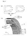
Fig. 1 is an axonometric view of a two-phase synchronous hybrid electric machine with transverse magnetic flux according to the invention, in partial cross-section;Figs. 2(A) to 2(C) are axonometric views of an assemble of rotor rings in one motor phase (examples A, B, C), showing a narrow insulating gap and insulating screws;Figs. 3(A) and 3(C) are an axonometric view of a circular array of stator yokes (one phase, example A) of the motor according to the invention, in partial cross-section, and a side view of the stator yokes, respectively;Figs. 4(A) and 4(B) are an axonometric view of a circular array of stator yokes (one phase, example B) of the motor according to the invention, in partial cross-section, and a side view of the stator yoke, respectively; and,Figs. 5(A) and 5(B) are an axonometric view of a circular array of stator yokes (one phase, example C) of the motor according to the invention, in partial cross-section, and a side view of the stator yoke, respectively. -
- 1 Stator armature
- 2 Circular array
- 3, 3b, 3c Stator yokes
- 4 Winding
- 5 Motor axis
- 6 Stator pole
- 7 Stator pole
- 9 Ball bearing
- 11 Rotor armature
- 12 Copper ring (conducting ring)
- 13 Rotor assembly
- 14, 15, 14b,
15b 14c, 15c Cogged rings - 16 to 19, 16b to 19b, 16c to 19c Rotor poles
- 21 Screw
- 22 Insulating gap
- 23b, 24b, 23c, 24c Component parts of the stator yoke
- With respect to the drawings, examples of the present invention will now be explained.
- In
Fig. 1 , a first embodiment (example A) of a two-phase synchronous hybrid electric machine with transverse magnetic flux according to the invention is shown. To each side of the stator armature (1) is fixed a circular array (2) of U-shaped stator yokes (3) which encircle the stator winding (4) of the corresponding phase. The windings (4) are coaxial with the motor axis (5). - Stator yokes (3) with salient poles (6, 7) are more precisely shown in
Fig. 3 . The yokes may be of bulk iron but it is better that the yokes (3) are lamination packages, as it is shown inFigs. 1 and3 . - The rotor armature (11) connected to the stator armature (1) via ball bearings (9), is fitted with a massive copper ring (12) to which on each side an assembly (13) of rotor rings is fixed. This assembly (13), which is more precisely shown in
Fig. 2(A) (example A), consists of two cogged rings (14, 15) of ferromagnetic material fitted with equally spaced rotor poles (16, 17, 18, 19) and a magnetized disk (20). - The ferromagnetic cogged rings (14, 15) can be lamination packages, just like the stator yokes (3). (For the sake of clarity, these lamellae are not shown in
Fig. 2 ). The magnetized disk (20) is magnetized in the axial direction so as to produce a magnetic flux that can be directed either from the cogged ring (14) to the cogged ring (15) or in the opposite direction. The cogged rings (14, 15) and the magnetized disk (20) can be held together by means of screws (21), as shown more precisely inFig. 2 (A) . The same screws (21) can be used to fasten the rotor assembly (13) to the copper ring (12). - The cogged rings (14, 15) are electrically insulated from the supporting copper ring (12), this can be achieved for instance by applying a thin ceramic layer onto the stems of the screws (21) and onto the surface of the copper ring (12). The cogged rings (14, 15) have in at least one place a narrow insulating gap (22) to prevent free circulation of circular eddy currents, as is shown in
Fig. 2(A) . The same holds for the magnetized disk (20). - The cogged rotor rings (14, 15) and the stator yokes (3) are in the magnetic juncture; in each phase the number of stator yokes (3) is equal to the number of rotor poles (16, 17, 18, 19). The cogged rings (14, 15) in the assembly (13) of variant A are placed such that their outer poles (18, 19) are mutually shifted for one half of pole division, as shown in
Fig. 2(A) (example A). The same holds for the inner poles (16, 17). - In example A there is also mutual shift for one half of pole division between the poles (16, 18) of the first cogged ring (14), and similarly, there is also mutual shift between the poles (17, 19) of the second cogged ring (15). In
Fig. 2 (A) this relative position of opposing poles on inner and outer rotor circumference is more precisely shown by the dotted line S. - At a chose moment of observation, when the stator pole (6) covers the rotor pole (17) and, due to the shift of the cogged ring (14) against the cogged ring (15), the stator pole (7) covers the rotor pole (18), a current starts running in the winding (4) in such a direction that the density of magnetic field in the air gap between the stator pole (6) and the rotor pole (17) of the cogged ring (15), and between the stator pole (7) and the rotor pole (18) of the cogged ring (14) decreases, while the density of magnetic field in the air gaps between the stator pole (6) and the rotor pole (16) of the cogged ring (14) and between the stator pole (7) and the rotor pole (19) of the cogged ring (15) increases.
- Because of such momentous magnetic state the stator poles attract the rotor poles towards a position which is shifted by 1/2 of the pole's division with regard to the position at the chosen moment, so that in the end position of observation the stator pole (6) coincides with the rotor pole (16) of the cogged ring (14), and the stator pole (7) coincides with the rotor pole (19) of the cogged ring (15). At this moment the direction of current in the winding (4) inverts. This causes the rotor to move forwards, so that it reassumes the initially observed position of mutual covering of the rotor and stator poles. Through the change of current direction in the stator winding (4) the rotation of rotor is enabled, while the change itself can be achieved by electronic commutation.
- In motors with transverse magnetic flux considerable voltages are induced in all active parts which are coaxial with the motor axis (5). In the motor according to the invention, such parts are the cogged rings (14, 15) and the magnetized disk (20). These ring-like parts (14, 15, 20) are cut by insulating gap (22) in at least one place so that the induced voltage cannot drive circular currents around these rings (14, 15, 20). This is shown in
Fig. 2(A) (example A). The gap (22) can be filled with some electrically insulating adhesive material. The induced currents also cannot bypass the insulating gap via the copper ring (12) since the rings (14, 15, 20) are electrically insulated from the supporting copper ring (12). - In this way eddy current losses in the active parts of the motor are considerably reduced, which is significant especially at high motor speed and at high torque when the magnetic flux changes are great. It can be shown that the insulating gap (22) in each rotor assembly (13) can reduce eddy current losses in the cogged iron rings by a factor of approximately 10.
- There are also eddy current losses in the passive parts of the motor, namely in the rotor armature (11), stator armature (1), and ball bearings (9). Unluckily, they cannot be reduced in the same way since these parts are the supporting parts of the motor. Namely, insulating gaps in the supporting parts would reduce the mechanical precision and would spoil compactness of the motor. According to the invention, this problem is solved by a massive copper ring (12) which is placed outside the active area with a strong magnetic field, but still is in close vicinity of this active area. So this ring (12) does not affect the magnetic field in the active parts, yet it considerably affects the dissipated magnetic fields outside of the active area.
- This dissipated magnetic flux of the machine with transverse magnetic flux induces circular AC electric current around the copper ring (12). This induced AC current produces its own magnetic flux, which is coupled to the original dissipated magnetic flux. A detailed analysis ( according to conventional methods in theory and practice of electric machines) shows that the original dissipated AC magnetic flux and the induced AC magnetic flux approximately cancel each other if the quantity Q defined by relation:

is much less than 1.
In the above formula the following notations are used: - ξ is the specific electric resistance of the material used in the ring (12). For copper at working temperature of the motor, ξ is approximately 2·10-8Ωm.
µo is the induction constant (4π·10-7Vs/Am)
S is the cross-section area of the ring (12) in units of m2. InFig. 1 this is marked by the shaded cross-section of the ring (12).
ω is the circular frequency of the electric current in the motor coils (in units of s-1). Usually we take ω at nominal speed of the motor.
ξ is a dimensionless parameter depending on the geometry and precise proportions of the motor. The parameter ξ is usually between 0.5 and 0.7 for constructional designs where the conducting ring (12) is exactly between the active areas of the two phases of the motor with transverse magnetic flux. This is the case shown inFig. 1 where we see the conducting ring (12) between two cogged rings (14) of the two phases of the motor according to the invention. If the conducting ring (12) is not in this central position, then the parameter ζ is smaller. The construction with greater ζ is advantageous (see the text below). - The solution according to the present invention applies in most of the cases, except in such cases when the nominal motor speed is so low that we cannot get Q smaller than unity. In these exceptional cases the copper ring (12) is not used, and the rotor armature (11) can extend into the area near the active parts of the motor. Then it is good that the armatures (11) and (1) are then made of materials with much higher electric resistance ξ, since in such cases we have no other means to reduce eddy currents in the passive parts of the motor.
- Luckily, it turns out that for most practical application, the quantity Q is indeed quite smaller than 1. In every such case the dissipated magnetic flux is nearly completely cancelled out. Then the eddy current losses in the motor housing (stator armature) and in the rotor armature are very small. What remains are practically only the losses in the copper ring (12), but also these losses are much smaller than ohmic losses in the motor coils (the ratio between these two types of losses is just of the order of Q). Hence, if Q is much smaller than 1, then losses in the copper ring are negligible if compared to the ohmic losses in the coils (4). Further, eddy current losses in rotor and stator armature (11, 1) are in the case of small Q even much smaller than losses in the copper ring (12). Hence, overall eddy current losses are much smaller than eddy current losses in motors without the conducting ring (12) where losses in the armature would be quite large.
- It is evident that one should look for such a constructional solution of the machine with transverse magnetic flux that the parameter Q is much smaller than 1. This can be achieved by a conducting ring (12) with great cross-section S and small specific electric resistance ξ. Therefore the proposed choice is use of a massive copper ring (12). The holes for screws (21) should not be too wide so that the passage of electric current along the conducting ring (12) is not considerably impeded by them.
- The ring (12) forms an attached part of the rotor armature (11), so instead of pure copper (oxygen free & high conductivity copper) which is too soft for mechanical applications, one can make a compromise by use of copper with small addition of alloying metals. In this way one can quite easily and sufficiently increase the mechanical stiffness without excessively increasing the specific resistance ξ.
- Therefore, the problem of eddy current losses has been successfully solved by a hybrid synchronous machine with transverse magnetic flux, the rotor armature (11) comprising of at least one massive copper ring (12) in close vicinity of the active motor parts, and the rotor rings (14, 15, 20) having at least one cross-cut insulating gap (22).
- The described solution also improves the compactness of motor. Namely, the cogged iron rings (14, 15) with cross-cut insulating gaps (22) are more flexible than rings without these gaps (22), especially in the case they are lamination packages. Hence, the rotor rings (14, 15, 20) need a firm support, which can be easily provided by the massive copper ring (12).
- Another improvement in motor compactness, which is also a matter of the present invention, is shown in
Figs. 4 and5 . Constructions with these improvements are described as examples B and C, which introduce some modifications to the original example A shown inFig. 3 . As we see inFig. 1 and inFig. 3 , in example A the U-shaped stator yokes (3) in the circular array (2) are separated from each other. Some additional part (e.g., made from plastic material) must provide for the desired separation between the yokes (3) in example A. - As we see in
Fig. 4 , in example B this plastic part is no more necessary, since the stator yokes (3b) are not separated among themselves. Instead of one simple and symmetrical yoke (3) in variant A, in variant B we have a yoke (3b) of more complicated shape. In fact, this yoke (3b) is a pair of two parts (23b, 24b). These two parts (23b, 24b) are equal, but the first part (23b) is turned upside down, while the second part (24b) is turned downside up, as is seen inFig. 4 . - In example B one yoke (3b) is carrying the same magnetic flux as one yoke (3) in the example A. But since there is no distance between the yokes (3b), each yoke (3b) is twice wider than the yoke (3) of variant A, and consequently the radial thickness of the yoke (3b) can be only one half of the corresponding thickness in variant A. This can be seen if we compare
Figs. 3 and4 . So also the housing of the motor can be smaller, which, together with dense packing of the stator yokes (3b), contributes to motor compactness. Another advantage is easier assembling of the motor, since in variant B there is no need to provide for separation between the stator yokes (3b). - Very similar argumentation holds also for example C (shown in
Figs. 2 (C) and5 ), wherein stator yokes (3c) are also assembled closely together into a circular array (2). Each yoke (3c) is in fact a pair of two parts (23c, 24c) which are again equal, with provision that the first part (23c) is turned upside down and the second part (24c) is turned downside up. Also the yokes (3c) make motor similarly compact and easy to assemble. - Due to different angular poison of stator poles (6, 7) in examples B and C, in examples B and C the relative poison of rotor poles slightly differs from the one described for example A. Corresponding rotor parts are shown in
Figs. 2(B) and 2 (C) . - In example B of
Fig. 2(B) , the cogged rings (14b, 15b) in the assembly (13) are placed such that their outer poles (18b, 19b) are not mutually shifted. The same holds for mutual shift of the inner poles (16b, 17b). There is also no mutual shift between the poles (16b, 18b) of the first cogged ring (14b), and similarly, there is also no mutual shift between the poles (17b, 19b) of the second cogged ring (15b). InFig. 2 (variant B) this relative position of opposing poles on inner and outer rotor circumference is more precisely shown by the dotted line s. - In example C, the cogged rings (14c, 15c) in the assembly (13) are placed such that their outer poles (18c, 19c) are mutually shifted for one half of pole division (like in example A), and the same holds for mutual shift of the inner poles (16c, 17c). But there is no mutual shift between the poles (16c, 18c) of the first cogged ring (14c), and similarly, there is also no mutual shift between the poles (17c, 19c) of the second cogged ring (15c). Again, in
Fig. 2(C) (example C) this relative poison of opposing poles on inner and outer rotor circumference is more precisely shown by the dotted line s. - In this way the same magnetic juncture of rotor and stator poles can be achieved in all three examples (A, B and C), which leads also to equivalent functioning in all three cases.
- As explained above, the hybrid synchronous electric machine driven by the transverse magnetic flux of the present invention is constituted to have the rotor and the stator, and the rotor armature has the cogged iron rings provided with at least one cross-cut insulating gap. Further, according to the present invention, the machine has the rotor, the stator and the conducting ring; the conducting ring is arranged coaxial with the motor axis and is in the close vicinity of the active area of the motor.
- According to the present invention, the hybrid synchronous motor having low eddy current losses can be obtained, because eddy currents in cogged iron rings are impeded by cross-cut insulating gaps in these same iron rings. In addition, eddy currents in all passive parts of the motor (like rotor armature, stator armature, and ball bearings) are negligible since the current induced in the copper ring neutralizes all the dissipated magnetic flux outside the active area of the motor.
- Further, according to the present invention, the hybrid synchronous motor can be realized which is very compact, strong and mechanically stable, despite low eddy current losses.
Claims (5)
- A hybrid synchronous electric machine comprising a rotor, a stator and a conducting ring (12), the conducting ring (12) being coaxial with a motor axis (5) and in close vicinity of an active area of the machine.
- The hybrid synchronous electric machine according to claim 1, wherein the conducting ring (12) is made of cupper.
- The hybrid synchronous electric machine according to claim 1 or 2, wherein the conducting ring (12) is formed as part of a rotor armature (11).
- The hybrid synchronous electric machine according to claim 1, 2 or 3, wherein the stator comprises at least one circular array (2), and the circular array (2) is constituted by U-shaped stator yokes (3) spaced with one another.
- The hybrid synchronous electric machine according to claim 1, 2 or 3, wherein the stator comprises at least one circular array (2), the circular array (2) comprises stator yokes (3b, 3c) closely arranged with each other, and each stator yoke asymmetrically consists of two identical, but mutually overturned iron parts (23b, 24b, 23c, 24c).
Applications Claiming Priority (2)
| Application Number | Priority Date | Filing Date | Title |
|---|---|---|---|
| EP01947959A EP1416619B1 (en) | 2001-07-09 | 2001-07-09 | Hybrid synchronous electric machine |
| PCT/JP2001/005980 WO2003007459A1 (en) | 2001-07-09 | 2001-07-09 | Hybrid synchronous electric machine |
Related Parent Applications (2)
| Application Number | Title | Priority Date | Filing Date |
|---|---|---|---|
| EP01947959.1 Division | 2001-07-09 | ||
| EP01947959A Division EP1416619B1 (en) | 2001-07-09 | 2001-07-09 | Hybrid synchronous electric machine |
Publications (2)
| Publication Number | Publication Date |
|---|---|
| EP2061140A2 true EP2061140A2 (en) | 2009-05-20 |
| EP2061140A3 EP2061140A3 (en) | 2011-08-10 |
Family
ID=11737532
Family Applications (2)
| Application Number | Title | Priority Date | Filing Date |
|---|---|---|---|
| EP09001533A Withdrawn EP2061140A3 (en) | 2001-07-09 | 2001-07-09 | Synchronous hybrid electric machine |
| EP01947959A Expired - Lifetime EP1416619B1 (en) | 2001-07-09 | 2001-07-09 | Hybrid synchronous electric machine |
Family Applications After (1)
| Application Number | Title | Priority Date | Filing Date |
|---|---|---|---|
| EP01947959A Expired - Lifetime EP1416619B1 (en) | 2001-07-09 | 2001-07-09 | Hybrid synchronous electric machine |
Country Status (5)
| Country | Link |
|---|---|
| US (1) | US7034425B2 (en) |
| EP (2) | EP2061140A3 (en) |
| JP (1) | JP4773053B2 (en) |
| SI (1) | SI1416619T1 (en) |
| WO (1) | WO2003007459A1 (en) |
Families Citing this family (36)
| Publication number | Priority date | Publication date | Assignee | Title |
|---|---|---|---|---|
| GB2425222B (en) * | 2005-04-12 | 2008-11-05 | Perpetuum Ltd | An electromechanical generator for converting mechanical vibrational energy into electrical energy |
| DE102005048570A1 (en) | 2005-10-10 | 2007-04-12 | Ortloff-Technologie Gmbh | Motor gearbox with torque motor and voltage wave gearbox |
| JP4193859B2 (en) | 2006-04-04 | 2008-12-10 | トヨタ自動車株式会社 | Motor and energization control device for motor |
| DE102006050201A1 (en) * | 2006-10-25 | 2008-04-30 | Robert Bosch Gmbh | Transverse flux machine and method for producing a transverse flux machine |
| US20080179982A1 (en) * | 2007-01-30 | 2008-07-31 | Arvinmeritor Technology, Llc | Transverse flux, switched reluctance, traction motor with bobbin wound coil, with integral liquid cooling loop |
| US20090026869A1 (en) * | 2007-07-24 | 2009-01-29 | Christian Kaehler | Transverse flux reluctance machine and method for manufacturing same |
| GB0717746D0 (en) * | 2007-09-12 | 2007-10-24 | Univ Edinburgh | Magnetic flux conducting unit |
| JP5539191B2 (en) * | 2008-05-14 | 2014-07-02 | 三菱電機株式会社 | Magnetic inductor type rotating machine and fluid transfer device using the same |
| DE102009021540B4 (en) * | 2008-10-30 | 2015-09-10 | Leantec Motor Gmbh & Co. Kg | Transversal flux motor as external rotor motor and drive method |
| WO2010062766A2 (en) * | 2008-11-03 | 2010-06-03 | Motor Excellence, Llc | Polyphase transverse and/or commutated flux systems |
| US8148841B1 (en) * | 2008-11-28 | 2012-04-03 | Scott Apthorp | Modular wind turbine system |
| EP3751704A1 (en) * | 2009-02-05 | 2020-12-16 | Evr Motors Ltd. | Electrical machine |
| US8035270B2 (en) * | 2009-06-30 | 2011-10-11 | American Axle & Manufacturing, Inc. | Wheel motor |
| JP5507967B2 (en) * | 2009-11-09 | 2014-05-28 | 株式会社日立製作所 | Rotating electric machine |
| JP5609514B2 (en) * | 2010-02-09 | 2014-10-22 | 富士電機株式会社 | Ring coil motor |
| CN101771331B (en) * | 2010-02-11 | 2012-05-30 | 哈尔滨工业大学 | Transverse magnetic flux superconducting synchronous motor |
| WO2011115632A1 (en) * | 2010-03-15 | 2011-09-22 | Motor Excellence Llc | Transverse and/or commutated flux systems configured to provide reduced flux leakage, hysteresis loss reduction, and phase matching |
| CN102959832B (en) * | 2010-03-15 | 2016-11-16 | 电扭矩机器股份有限公司 | There is the horizontal of phase deviation and/or commutation throughput systems |
| US8395291B2 (en) | 2010-03-15 | 2013-03-12 | Electric Torque Machines, Inc. | Transverse and/or commutated flux systems for electric bicycles |
| WO2012067895A2 (en) | 2010-11-17 | 2012-05-24 | Motor Excellence, Llc | Transverse and/or commutated flux system coil concepts |
| CN103477538A (en) | 2010-11-17 | 2013-12-25 | 电动转矩机器公司 | Transverse and/or commutated flux systems having segmented stator laminations |
| WO2012067896A2 (en) | 2010-11-17 | 2012-05-24 | Motor Excellence, Llc | Transverse and/or commutated flux systems having laminated and powdered metal portions |
| KR101259171B1 (en) * | 2011-09-26 | 2013-04-30 | 이형진 | High efficiency electric motor, high efficiency electric generator |
| JP5743988B2 (en) * | 2012-09-18 | 2015-07-01 | 株式会社東芝 | Transverse magnetic flux type motor |
| EP2941813B1 (en) | 2013-01-04 | 2023-09-27 | Moog Inc. | Metal ribbon stator and motor comprising same |
| US9281736B2 (en) | 2013-03-23 | 2016-03-08 | The Boeing Company | Virtual ellipse motor |
| CN103178669A (en) * | 2013-04-15 | 2013-06-26 | 王新 | Transversal flux phase section type brushless doubly-fed induction motor |
| CN105981262B (en) | 2013-09-18 | 2019-01-11 | Evr电动机有限公司 | Multipolar dynamo |
| KR20160087882A (en) * | 2013-11-20 | 2016-07-22 | 산산 다이 | Ac permanent-magnet switched reluctance electric motor |
| FR3018966A1 (en) | 2014-03-21 | 2015-09-25 | Mmt Sa | HYBRID ELECTRIC MACHINE |
| JP2017169343A (en) | 2016-03-16 | 2017-09-21 | 株式会社東芝 | Rotary electric machine, hoisting machine, and elevator |
| JP6649238B2 (en) | 2016-12-13 | 2020-02-19 | 株式会社東芝 | Rotating electric machines and robot devices |
| US10608481B2 (en) * | 2016-12-15 | 2020-03-31 | General Electric Company | Core of a transverse flux machine and an associated method thereof |
| RU177973U1 (en) * | 2017-04-21 | 2018-03-19 | федеральное государственное бюджетное образовательное учреждение высшего образования "Донской государственный технический университет" (ДГТУ) | ELECTRIC MACHINE |
| US11608857B2 (en) * | 2020-04-14 | 2023-03-21 | Robert Lothar Monteith | Passive magnetic bearing |
| CA3170195A1 (en) | 2020-09-21 | 2022-03-24 | Evr Motors Ltd. | Radial flux electric machine |
Citations (1)
| Publication number | Priority date | Publication date | Assignee | Title |
|---|---|---|---|---|
| EP0544200A1 (en) | 1991-11-22 | 1993-06-02 | Andrej Detela | Hybrid synchronous machine with transverse magnetic flux |
Family Cites Families (25)
| Publication number | Priority date | Publication date | Assignee | Title |
|---|---|---|---|---|
| GB888462A (en) * | 1957-04-09 | 1962-01-31 | Ferranti Ltd | Improvements relating to step-by-step motors |
| US3206623A (en) * | 1962-04-20 | 1965-09-14 | Superior Electric Co | Electric synchronous inductor motor |
| DE2053262B2 (en) * | 1970-10-30 | 1972-09-21 | Robert Bosch Gmbh, 7000 Stuttgart | AC voltage generator for speed measurement, in particular for an anti-lock device of a vehicle brake system |
| JPS50143008A (en) | 1974-05-08 | 1975-11-18 | ||
| US4198582A (en) * | 1977-06-24 | 1980-04-15 | Exxon Research & Engineering Co. | High performance stepper motor |
| US4672247A (en) * | 1984-12-27 | 1987-06-09 | North American Philips Corporation | Synchronous or stepping motor with equal-torque stepping |
| JPH02228241A (en) | 1989-02-28 | 1990-09-11 | Nippon Seimitsu Kogyo Kk | Stepping motor |
| SE463061B (en) * | 1989-11-20 | 1990-10-01 | Svante Gustav Adolf Von Zweygb | PERMANENT MAGNETIZED SYNCHRON MACHINE DESIGNED ACCORDING TO THE PRINCIPAL TRANSFORM FLOW PRINCIPLE |
| FR2664105B1 (en) | 1990-07-02 | 1995-06-09 | Radio Energie | ROTARY STEPPER MOTOR WITH VARIABLE RELUCTANCE WITH TRANSVERSE FLOW. |
| US5130593A (en) * | 1990-09-26 | 1992-07-14 | Connell James J | Inductor alternators |
| US5304882A (en) | 1992-05-11 | 1994-04-19 | Electric Power Research Institute, Inc. | Variable reluctance motors with permanent magnet excitation |
| JPH06319249A (en) * | 1993-02-19 | 1994-11-15 | Iwao Shibata | Hybrid type pulse motor endowed with torque characteristic of induction motor provided with divided induction winding |
| JPH06351206A (en) * | 1993-04-14 | 1994-12-22 | Meidensha Corp | Hybrid excitation-type permanent-magnet synchronous rotating machine |
| JPH07253125A (en) * | 1994-03-14 | 1995-10-03 | Mitsubishi Electric Corp | Magnetic particle type connection device |
| CA2208482C (en) * | 1994-12-21 | 2000-04-11 | Wolfgang Hill | Transverse flux machine |
| GB9516497D0 (en) | 1995-08-11 | 1995-10-11 | Rolls Royce Power Eng | Electrical machine |
| CN2264438Y (en) * | 1996-05-06 | 1997-10-08 | 韩泰勋 | Sheet inserting a.c low speed synchronous motor |
| US6043579A (en) * | 1996-07-03 | 2000-03-28 | Hill; Wolfgang | Permanently excited transverse flux machine |
| DE19800667C2 (en) * | 1998-01-10 | 2000-10-12 | Herbert Weh | Transverse flux machine with a low-mass passive rotor |
| US6091168A (en) * | 1998-12-22 | 2000-07-18 | Hamilton Sundstrand Corporation | Rotor for a dynamoelectric machine |
| JP2000197301A (en) | 1998-12-24 | 2000-07-14 | Sony Corp | Motor |
| US6483212B1 (en) * | 1999-10-06 | 2002-11-19 | Asmo Co., Ltd. | Reluctance-type electric motor |
| SI20497B (en) * | 2000-01-14 | 2008-08-31 | Harmonic Drive Systems | Synchronous hybrid electric machine with toroid coil |
| US6492758B1 (en) * | 2000-02-25 | 2002-12-10 | Fisher & Paykel Limited | Polyphase transverse flux motor |
| AU2002253352A1 (en) * | 2001-05-02 | 2002-11-11 | Newage International Limited | A toroidal electrical machine and an annular winding carrier therefor |
-
2001
- 2001-07-09 SI SI200130997T patent/SI1416619T1/en unknown
- 2001-07-09 US US10/482,308 patent/US7034425B2/en not_active Expired - Lifetime
- 2001-07-09 EP EP09001533A patent/EP2061140A3/en not_active Withdrawn
- 2001-07-09 EP EP01947959A patent/EP1416619B1/en not_active Expired - Lifetime
- 2001-07-09 JP JP2003513111A patent/JP4773053B2/en not_active Expired - Lifetime
- 2001-07-09 WO PCT/JP2001/005980 patent/WO2003007459A1/en active Application Filing
Patent Citations (1)
| Publication number | Priority date | Publication date | Assignee | Title |
|---|---|---|---|---|
| EP0544200A1 (en) | 1991-11-22 | 1993-06-02 | Andrej Detela | Hybrid synchronous machine with transverse magnetic flux |
Also Published As
| Publication number | Publication date |
|---|---|
| EP1416619B1 (en) | 2011-06-08 |
| EP1416619A4 (en) | 2008-02-27 |
| JPWO2003007459A1 (en) | 2004-11-04 |
| US7034425B2 (en) | 2006-04-25 |
| SI1416619T1 (en) | 2011-10-28 |
| EP2061140A3 (en) | 2011-08-10 |
| EP1416619A1 (en) | 2004-05-06 |
| US20040207281A1 (en) | 2004-10-21 |
| JP4773053B2 (en) | 2011-09-14 |
| WO2003007459A1 (en) | 2003-01-23 |
Similar Documents
| Publication | Publication Date | Title |
|---|---|---|
| US7034425B2 (en) | Hybrid synchronous electric machine | |
| US6172438B1 (en) | Two-phase permanent-magnet electric rotating machine | |
| US5977684A (en) | Rotating machine configurable as true DC generator or motor | |
| EP1734645B1 (en) | Axial air gap-type electric motor | |
| US6700271B2 (en) | Hybrid synchronous motor equipped with toroidal winding | |
| US5521451A (en) | Low-cost stepping or synchronous motor | |
| JPS63257448A (en) | Electronically rectified dc motor without collector | |
| WO2005034312B1 (en) | Rotary pump with electromagnetic lcr bearing | |
| US5089730A (en) | Low noise DC electric motor | |
| JP2002354767A (en) | Magnetic levitation motor | |
| US6636007B2 (en) | DC brushless vibration motor | |
| JP2010110128A (en) | Permanent magnet rotating electrical machine | |
| US11569717B2 (en) | Axial flux rotary electric machine | |
| US20140084716A1 (en) | Rotating electrical machine with so-called double homopolar structure | |
| US6781260B2 (en) | Permanent magnet type rotary machine | |
| EP1300931A2 (en) | Brushless DC motor | |
| US6744163B2 (en) | Vibration type brushless motor | |
| KR100213572B1 (en) | Double stator and coress-type bldc motor | |
| US7977827B2 (en) | Stepper motor device | |
| JP2003333813A (en) | Rotor of synchronous reluctance motor | |
| US5907205A (en) | Constant reluctance rotating magnetic field devices with laminationless stator | |
| JPH11332211A (en) | Cylindrical linear motor | |
| JP4264021B2 (en) | Cylinder type linear synchronous motor | |
| JP2008187863A (en) | Axial gap rotary electric machine and compressor | |
| JP2017041938A (en) | Axial gap rotary electric machine |
Legal Events
| Date | Code | Title | Description |
|---|---|---|---|
| PUAI | Public reference made under article 153(3) epc to a published international application that has entered the european phase |
Free format text: ORIGINAL CODE: 0009012 |
|
| AC | Divisional application: reference to earlier application |
Ref document number: 1416619 Country of ref document: EP Kind code of ref document: P |
|
| AK | Designated contracting states |
Kind code of ref document: A2 Designated state(s): DE GB SE |
|
| AX | Request for extension of the european patent |
Extension state: SI |
|
| PUAL | Search report despatched |
Free format text: ORIGINAL CODE: 0009013 |
|
| AK | Designated contracting states |
Kind code of ref document: A3 Designated state(s): DE GB SE |
|
| AX | Request for extension of the european patent |
Extension state: SI |
|
| RIC1 | Information provided on ipc code assigned before grant |
Ipc: H02K 21/12 20060101AFI20110705BHEP |
|
| AKY | No designation fees paid | ||
| REG | Reference to a national code |
Ref country code: DE Ref legal event code: R108 Effective date: 20120419 |
|
| STAA | Information on the status of an ep patent application or granted ep patent |
Free format text: STATUS: THE APPLICATION IS DEEMED TO BE WITHDRAWN |
|
| 18D | Application deemed to be withdrawn |
Effective date: 20120211 |