EP2060332A2 - Suction device for finely dispersed materials - Google Patents
Suction device for finely dispersed materials Download PDFInfo
- Publication number
- EP2060332A2 EP2060332A2 EP09003260A EP09003260A EP2060332A2 EP 2060332 A2 EP2060332 A2 EP 2060332A2 EP 09003260 A EP09003260 A EP 09003260A EP 09003260 A EP09003260 A EP 09003260A EP 2060332 A2 EP2060332 A2 EP 2060332A2
- Authority
- EP
- European Patent Office
- Prior art keywords
- suction device
- clamping
- aer
- chamber
- suction
- Prior art date
- Legal status (The legal status is an assumption and is not a legal conclusion. Google has not performed a legal analysis and makes no representation as to the accuracy of the status listed.)
- Granted
Links
Images


Classifications
-
- B—PERFORMING OPERATIONS; TRANSPORTING
- B08—CLEANING
- B08B—CLEANING IN GENERAL; PREVENTION OF FOULING IN GENERAL
- B08B15/00—Preventing escape of dirt or fumes from the area where they are produced; Collecting or removing dirt or fumes from that area
- B08B15/007—Fume suction nozzles arranged on a closed or semi-closed surface, e.g. on a circular, ring-shaped or rectangular surface adjacent the area where fumes are produced
Definitions
- the invention relates to a suction device for finely divided and / or gaseous substances, which is formed as a hollow annular body with a central pour opening, at least one pipe connection leads into the interior of the annular body and in the wall defining the pouring opening a plurality of suction holes is formed, wherein the bores communicate via the interior of the hollow ring body with the pipe connection.
- a suction device of the type mentioned is from the WO 03/045593 A1 known.
- This device is designed for the suction of toxic gases, but does not take into account the problem of sucking powdered substances, especially in connection with the requirements that are made in the pharmaceutical industry.
- the known device would be contaminated in use when filling powdery substances after a short time with deposits , which could hardly be removed from the device, which is usually not allowed for hygienic reasons.
- An object of the invention is to provide an improved suction device which does not have the above-mentioned disadvantages.
- the ring body has at least one upper part and a lower part, wherein the upper part and lower part held together in use by a clamping means and are separable after opening the clamping means exposing the annular body interior.
- a suction device which can be adapted to any filling situation also in size and provides the best possible protection against contamination of the environment by escaping dust and aerosols, with operating errors, such as incorrect positioning of the suction head according to the prior art z. B. can not be effectively prevented by not well trained staff.
- the cleaning is quick and easy to carry out, which is an absolute necessity in many applications, especially in pharmaceutical companies
- the pouring opening is delimited by a lower, substantially cylindrical wall section and an adjoining upper, upwardly and outwardly widened conical wall section, wherein the suction bores are formed in the conical wall section. In this way, an upwardly directed vacuum cone can be built up over the pour opening during operation.
- suction bores have a rounding at least at their outer end region facing the pouring opening.
- the air duct can be kept particularly homogeneous, if that is provided between upper part and lower part partition plate with at least one passage opening, the annular body in the assembled state, at least one lower chamber and at least one upper chamber and the at least one lower chamber and the at least one upper Chamber via at least one passage opening communicate with each other. It is also advantageous if at least one upper, inner, annular chamber and at least one lower, outer chamber are provided, the pipe socket opening into the at least one lower, outer chamber and the suction bores into the at least one upper, inner chamber.
- a further improvement is in this case characterized in that an upper, inner, annular chamber is provided, which communicates with at least one upper, outer chamber portion, and the upper, outer chamber portion communicates with at least one outer, lower chamber via a passage opening of the separation plate, or when a guide surface which leads tangentially outwards is provided at the connection between the upper, inner, annular chamber with the at least one upper, outer chamber portion ,
- the suction device In order to enable rapid disassembly and assembly of the suction device is provided in a variant of the invention that is provided at the connection between the upper, inner, annular chamber with the at least one upper, outer chamber portion, a guide surface leading tangentially outwards.
- the quick-release head has a clamping lever with a supportable against the lower surface of the lower part eccentric surface and can be brought into train with the lower end of the clamping bolt.
- each clamping bolt is cylindrical, wherein the support head is widened with respect to the cross section and the clamping bolt has at the opposite end a passing into a holding head annular groove for cooperation with the quick-release head.
- the tensioning lever has a fork-shaped end with holes in which a transverse bolt is inserted, and a standing with the clamping bolt in conjunction threaded draw bolt is screwed into a radial threaded bore of the transverse bolt.
- an advantageous variant may be characterized in that the clamping lever has a fork-shaped end with holes in which a transverse bolt is inserted, and a standing with the clamping bolt threaded draw bolt is screwed into a radial threaded bore of the transverse bolt.
- the clamping bolt is connected to the threaded pull pin via a clamping piece, the clamping bolt is mounted with its holding head in a slot of the clamping piece and the threaded pull pin is screwed into a radial threaded bore of a clamping pin, in two opposite Holes of the clamping piece is added.
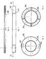
- the shape of the suction device AER corresponds to a hollow ring body, it may also be referred to as toroidal, wherein a central pour opening SOE is bounded by a wall WAN and in this wall a plurality of suction holes ASB is formed, in the present example 50 holes. More precisely, the bores are formed in an upper, upwardly and outwardly conically widened wall section KWA, which merges downward into a substantially cylindrical wall section ZWA.
- the holes ASB are in a manner to be described in more detail below about the interior of the hollow body with a pipe connection, namely a pipe socket in connection ROS in the operating state of the device via a suction line, not shown, such as hose, is connected to a suction device. Thanks to the obliquely upward bores ASB ambient air is sucked in and formed a kind of vacuum cone over the pouring spout.
- the suction holes ASB have a rounding ARU at least at their outer end pointing toward the pouring opening SOE, in the present case, however, at both end regions, by means of which a local vortex formation and thus the noise development are reduced.
- the suction device can be easily cleaned. Therefore, it can be provided that it consists of two or more parts and can be dismantled, which will be described in more detail below.
- the suction device AER consists of at least one upper part OTE and a lower part UTE, wherein the upper part and lower part are held together in the state of use by a clamping device SSM and after opening of the clamping means to expose the annular body interior are separable.
- a separating plate TRP located between the upper part OTE and lower part UTE is provided with at least one passage opening DUT.
- the top part OTE is in the Fig. 3 to 5 shown in detail, the lower part UTE in the FIGS. 7 and 9 and the partition plate TRP in the 6 and 8 ,
- TRP partition plate
- UTE has proven in practice polypropylene, but it should be clear that the skilled person depending on the application, other useful materials are available.
- the annular body of the suction device AER has at least one lower chamber UKA and at least one upper chamber OKA, the at least one lower chamber UKA and the at least one upper chamber OKA communicating with each other via at least one passage opening DUT, in the present example two stand.
- a multi-part upper, inner, annular chamber OKA and a lower, about 180 ° extending outer chamber UKA is provided, wherein the pipe socket ROS in this lower, outer chamber UKA and the suction holes ASB in the upper, inner chamber OKA lead.
- the air together with any existing dust or a gas or aerosol is thus sucked through the suction holes ASB first into the inner, upper chamber OKA and passes from here to outer sections of the chamber, wherein tangentially leading outward guide surfaces LEF (see Fig. 5 ) lead the flow. From these said chamber sections, the air through the openings DUT of the partition plate (see Fig. 8 ) down into the lower, outer chamber UKA (see Fig.
- the air flow rate is on the order of 130 m 3 / h with an outer dimension of the ring body of 480 mm.
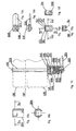
- the quick-release head SSK has a substantially U-shaped clamping piece PLC with two parallel legs SEL. In bores of the two legs a cylindrical clamping pin ZSS is added, which has a lying between the legs, the clamping pin radially passing through threaded hole GBO.
- the two legs SEL are connected at one end via a web STE, in which a slot SLI is formed.
- the clamping bolt SPB is introduced with its holding head HAK, wherein the diameter of the holding head HAK is less than the inner spacing of the legs and the slot width greater than the diameter of the clamping bolt SPB at the location of its annular groove RNT.
- the clamping piece SPS with the clamping pin ZSS lies within a slotted pressure sleeve DRH, which can be supported with an open end via an intermediate disk SEI on the lower part UTE.
- a slotted pressure sleeve DRH which can be supported with an open end via an intermediate disk SEI on the lower part UTE.
- the clamping bolt SPB with the quick release head SSK could also be used upside down. In this case, the pressure sleeve would be supported on the top OTE
- the assembly of the suction device takes place in the manner described below.
- the top OTE is placed with its top on a base, after previously z. B. two clamping bolts SPB were inserted through holes DBO. Then, the partition plate TRP is placed over it, wherein the bolts SPB pass through the associated holes DBO of the partition plate TRP. Finally, the lower part UTE is placed over it so that the free ends of the bolts SPB protrude from its underside. Then the quick release head SSK is pushed with the clamping lever SPH open so that the end of the bolt with the holding head HAK passes through the slot of the pressure sleeve DRH in the slot SLI of the clamping piece SPS. Then the clamping lever SPH is closed by tilting to its end position.
- the clamping force can be adjusted individually, since in this case the Gewindzugbolzen GZB is rotated with respect to the threaded bore GBO in the clamping pin ZSS.
- the remaining clamping bolts SPB and quick release heads SSK can be mounted.
- the dismantling of the device takes place mutatis mutandis after respective opening of the quick release heads SSK.
- a funnel in a poorly closed clamping lever of the quick release head SSK falls, are formed at the ends of the slot SLI of the clamping piece SPS two locking lugs SIN ( Fig. 10f ).
- the support head ASK of the clamping bolt SPB can of course also be designed differently than in Fig. 10
- it may be a hexagon head received in a correspondingly shaped recess of the top OTE.
- the quick release head SSK can also be simpler in construction and, for example, consist only of a spring plate with a slot which is pushed onto the end of the clamping bolt such that the slot comprises the annular groove RNT.
Abstract
Description
Die Erfindung bezieht sich auf eine Absaugeinrichtung für fein verteilte und/oder gasförmige Stoffe, welche als hohler Ringkörper mit einer zentralen Schüttöffnung ausgebildet ist, zumindest ein Rohranschluss in das Innere des Ringkörpers führt und in der die Schüttöffnung begrenzenden Wandung eine Vielzahl von Ansaugbohrungen ausgebildet ist, wobei die Bohrungen über das Innere des hohlen Ringkörpers mit dem Rohranschluss in Verbindung stehen.The invention relates to a suction device for finely divided and / or gaseous substances, which is formed as a hollow annular body with a central pour opening, at least one pipe connection leads into the interior of the annular body and in the wall defining the pouring opening a plurality of suction holes is formed, wherein the bores communicate via the interior of the hollow ring body with the pipe connection.
Insbesondere in der chemischen Industrie, aber auch in anderen Industriezweigen, wie der Lebensmittelindustrie, tritt das Problem auf, dass beim Ein- oder Umfüllen vor allem pulverförmiger Stoffe Staub- oder Aerosolnebel entstehen, die nicht in den Bestimmungsort, z. B. einen Reaktionsbehälter, gelangen, sondern in die Umgebung. Dadurch kommt es zu einer unerwünschten Verunreinigung, die außerdem Gefahrenmomente, z. B. beim Ein-/Umfüllen giftiger, explosiver oder anderweitig gefährlicher Stoffe, in sich birgt. Verstärkt werden diese Probleme in Reinräumen.In particular, in the chemical industry, but also in other industries, such as the food industry, the problem arises that when loading or transferring especially powdery substances dust or aerosol mist arise that is not in the destination, eg. B. a reaction vessel, but in the environment. This leads to an undesirable contamination, which also dangerous moments, eg. B. when filling / transferring toxic, explosive or otherwise hazardous substances, entails. Reinforced these problems in cleanrooms.
Um eine Verunreinigung der Umgebung zu vermeiden, ist es nach dem Stand der Technik bekannt, einen auf einem beweglichen Arm montierten, über eine Saugleitung an eine Absaugvorrichtung, im Prinzip einen Staubsauger, angeschlossenen Saugkopf in die Nähe der Einschüttöffnung, beispielsweise eines Trichters, zu platzieren. Diese Lösung ist jedoch mit einigen Nachteilen verbunden, denn einerseits muss jedes Mal eine optimale Lage des Absaugkopfes gefunden werden. Andererseits ist eine Absaugung nur in Richtung des Saugkopfes möglich und nach der Gegenrichtung entweichender Staub wird nicht oder nur schlecht abgesaugt. Man kann zwar die Saugleistung erhöhen, um die Absaugwirkung zu verbessern, läuft aber dann Gefahr, dass auch das einzufüllende pulverförmige Schüttgut selbst abgesaugt wird.In order to avoid contamination of the environment, it is known in the prior art to place a mounted on a movable arm, via a suction line to a suction device, in principle a vacuum cleaner, connected suction head in the vicinity of the pouring, for example, a funnel to place , However, this solution is associated with some disadvantages, because on the one hand every time an optimal position of the suction head must be found. On the other hand, an extraction only in the direction of the suction head is possible and after the opposite direction escaping dust is not or only poorly aspirated. Although it is possible to increase the suction power in order to improve the suction effect, but then runs the risk that even the pulverulent bulk material to be filled is extracted by itself.
Eine Absaugvorrichtung der eingangs genannten Art ist aus der
Eine Aufgabe der Erfindung liegt darin, eine verbesserte Absaugeinrichtung zu schaffen, welche die oben erwähnten Nachteile nicht aufweist.An object of the invention is to provide an improved suction device which does not have the above-mentioned disadvantages.
Diese Aufgabe wird mit einer Absaugeinrichtung der eingangs genannte Art gelöst, bei welcher erfindungsgemäß der Ringkörper zumindest einen Oberteil und einen Unterteil aufweist, wobei Oberteil und Unterteil im Gebrauchszustand durch ein Spannmittel zusammengehalten und nach Öffnen des Spannmittels unter Freilegung des Ringkörperinneren trennbar sind.This object is achieved with a suction device of the type mentioned, in which according to the invention the ring body has at least one upper part and a lower part, wherein the upper part and lower part held together in use by a clamping means and are separable after opening the clamping means exposing the annular body interior.
Dank der Erfindung ist eine Absaugeinrichtung geschaffen, die an jede Einfüllsituation auch der Größe nach angepasst werden kann und die bestmöglichsten Schutz vor Verunreinigung der Umgebung durch entweichenden Staub und Aerosole bietet, wobei Bedienungsfehler, wie ein falsches Positionieren des Absaugkopfes nach dem Stand der Technik z. B. durch nicht gut ausgebildetes Personal de facto verhindert werden können. Die Reinigung ist rasch und einfach durchführbar, was in vielen Anwendungsfällen insbesondere in pharmazeutischen Betrieben eine absolute Notwendigkeit istThanks to the invention, a suction device is provided which can be adapted to any filling situation also in size and provides the best possible protection against contamination of the environment by escaping dust and aerosols, with operating errors, such as incorrect positioning of the suction head according to the prior art z. B. can not be effectively prevented by not well trained staff. The cleaning is quick and easy to carry out, which is an absolute necessity in many applications, especially in pharmaceutical companies
Bei einer vorteilhaften Ausführung ist vorgesehen, dass die Schüttöffnung von einem unteren, im Wesentlichen zylindrischen Wandabschnitt und einem daran anschließenden oberen, nach oben und außen erweiterten konischen Wandabschnitt begrenzt ist, wobei die Ansaugbohrungen in dem konischen Wandabschnitt ausgebildet sind. Auf diese Weise lässt sich im Betrieb ein nach oben gerichteter Unterdruckkegel über der Schüttöffnung aufbauen.In an advantageous embodiment, it is provided that the pouring opening is delimited by a lower, substantially cylindrical wall section and an adjoining upper, upwardly and outwardly widened conical wall section, wherein the suction bores are formed in the conical wall section. In this way, an upwardly directed vacuum cone can be built up over the pour opening during operation.
Vorteilhaft im Sinne einer geringen Geräuschentwicklung ist es weiters, wenn die Absaugbohrungen zumindest an ihrem äußeren, zur Schüttöffnung weisenden Endbereich eine Abrundung aufweisen.It is also advantageous in terms of low noise development if the suction bores have a rounding at least at their outer end region facing the pouring opening.
Die Luftführung kann besonders homogen gehalten werden, falls dass eine zwischen Oberteil und Unterteil gelegene Trennplatte mit zumindest einer Durchtrittsöffnung vorgesehen ist, der Ringkörper im zusammengesetzten Zustand zumindest eine untere Kammer und zumindest eine obere Kammer aufweist und die zumindest eine untere Kammer und die zumindest eine obere Kammer über zumindest eine Durchtrittsöffnung miteinander in Verbindung stehen. Hierbei ist es auch vorteilhaft, wenn zumindest eine obere, innere, ringförmige Kammer und zumindest eine untere, äußere Kammer vorgesehen sind, wobei der Rohrstutzen in die zumindest eine untere, äußere Kammer und die Ansaugbohrungen in die zumindest eine obere, innere Kammer münden. Eine weitere Verbesserung zeichnet sich in diesem Fall dadurch aus, dass eine obere, innere, ringförmige Kammer vorgesehen ist, welche mit zumindest einem oberen, äußeren Kammerabschnitt in Verbindung steht, und der obere, äußere Kammerabschnitt über eine Durchtrittsöffnung der Trennplatte mit zumindest einer äußeren, unteren Kammer in Verbindung steht bzw. wenn an der Verbindung zwischen der oberen, inneren, ringförmigen Kammer mit dem zumindest einem oberen, äußeren Kammerabschnitt eine tangential nach außen führende Leitfläche vorgesehen ist.The air duct can be kept particularly homogeneous, if that is provided between upper part and lower part partition plate with at least one passage opening, the annular body in the assembled state, at least one lower chamber and at least one upper chamber and the at least one lower chamber and the at least one upper Chamber via at least one passage opening communicate with each other. It is also advantageous if at least one upper, inner, annular chamber and at least one lower, outer chamber are provided, the pipe socket opening into the at least one lower, outer chamber and the suction bores into the at least one upper, inner chamber. A further improvement is in this case characterized in that an upper, inner, annular chamber is provided, which communicates with at least one upper, outer chamber portion, and the upper, outer chamber portion communicates with at least one outer, lower chamber via a passage opening of the separation plate, or when a guide surface which leads tangentially outwards is provided at the connection between the upper, inner, annular chamber with the at least one upper, outer chamber portion ,
Um eine rasches Zerlegen und Zusammensetzen der Absaugeinrichtung zu ermöglichen, ist bei einer Variante der Erfindung vorgesehen, dass an der Verbindung zwischen der oberen, inneren, ringförmigen Kammer mit dem zumindest einem oberen, äußeren Kammerabschnitt eine tangential nach außen führende Leitfläche vorgesehen ist. Dabei ist eine Ausführung besonders praxistauglich, bei welcher der Schnellspannkopf einen Spannhebel mit einer gegen die Unterfläche des Unterteils abstützbaren Exzenterfläche aufweist und mit dem unteren Ende des Spannbolzens auf Zug in Eingriff gebracht werden kann.In order to enable rapid disassembly and assembly of the suction device is provided in a variant of the invention that is provided at the connection between the upper, inner, annular chamber with the at least one upper, outer chamber portion, a guide surface leading tangentially outwards. In this case, an embodiment is particularly practicable, in which the quick-release head has a clamping lever with a supportable against the lower surface of the lower part eccentric surface and can be brought into train with the lower end of the clamping bolt.
Weiters ist es in bei den genannten Ausführungen zweckdienlich, wenn jeder Spannbolzens zylindrisch ausgebildet ist, wobei der Abstützkopf bezüglich des Querschnitts verbreitert ist und der Spannbolzen an dem gegenüberliegenden Ende eine in einen Haltekopf übergehende Ringnut für das Zusammenwirken mit dem Schnellspannkopf besitzt. Dabei kann vorgesehen sein, dass der Spannhebel ein gabelförmiges Ende mit Bohrungen besitzt, in welche ein Querbolzen eingesetzt ist, und ein mit dem Spannbolzen in Verbindung stehender Gewindezugbolzen in eine radiale Gewindebohrung des Querbolzens eingeschraubt ist.Furthermore, it is expedient in the aforementioned embodiments, when each clamping bolt is cylindrical, wherein the support head is widened with respect to the cross section and the clamping bolt has at the opposite end a passing into a holding head annular groove for cooperation with the quick-release head. It can be provided that the tensioning lever has a fork-shaped end with holes in which a transverse bolt is inserted, and a standing with the clamping bolt in conjunction threaded draw bolt is screwed into a radial threaded bore of the transverse bolt.
Hierbei kann sich eine vorteilhafte Variante dadurch auszeichnen, dass der Spannhebel ein gabelförmiges Ende mit Bohrungen besitzt, in welche ein Querbolzen eingesetzt ist, und ein mit dem Spannbolzen in Verbindung stehender Gewindezugbolzen in eine radiale Gewindebohrung des Querbolzens eingeschraubt ist.Here, an advantageous variant may be characterized in that the clamping lever has a fork-shaped end with holes in which a transverse bolt is inserted, and a standing with the clamping bolt threaded draw bolt is screwed into a radial threaded bore of the transverse bolt.
Bedienungsfreundlich ist eine Weiterbildung der Erfindung, bei welcher der Spannbolzen mit dem Gewindezugbolzen über ein Spannstück in Verbindung steht, wobei der Spannbolzen mit seinem Haltekopf in einen Schlitz des Spannstücks eingehängt ist und der Gewindezugbolzen in eine radiale Gewindebohrung eines Spannstifts eingeschraubt ist, der in zwei gegenüberliegenden Bohrungen des Spannstücks aufgenommen ist.Easy to use is a development of the invention in which the clamping bolt is connected to the threaded pull pin via a clamping piece, the clamping bolt is mounted with its holding head in a slot of the clamping piece and the threaded pull pin is screwed into a radial threaded bore of a clamping pin, in two opposite Holes of the clamping piece is added.
Um ein Verschmutzen weitgehend zu verhindern kann vorgesehen sein, dass zwischen der Exzenterfläche des Spannhebels und dem Unterteil eine Druckhülse angeordnet ist, in welcher das Spannstück untergebracht ist, wobei sich die Exzenterfläche über die Druckhülse an dem Unterteil abstützt.To prevent fouling largely can be provided that between the eccentric surface of the clamping lever and the lower part of a pressure sleeve is arranged, in which the clamping piece is housed, wherein the eccentric surface is supported on the lower part via the pressure sleeve.
Die Erfindung samt weiterer Vorteile ist im folgenden an Hand einer beispielsweisen Ausführungsform näher erläutert, die in der Zeichnung veranschaulicht ist. In dieser zeigen
- Fig. 1
- eine Absaugeinrichtung nach der Erfindung in einem Schnitt nach der Linie I-I der
Fig. 2 , - Fig. 2
- eine Draufsicht auf die Absaugeinrichtung nach
Fig. 1 , - Fig. 3
- in einem Schnitt wie
Fig. 1 den Oberteil der Absaueinrichtung, - Fig. 4
- in verkleinerter Draufsicht den Oberteil,
- Fig. 5
- einen Schnitt nach der Linie V-V der
Fig. 3 , verkleinert, - Fig. 6
- in einem Schnitt wie
Fig. 1 eine Trennplatte der Absaueinrichtung, - Fig. 7
- in einem Schnitt wie
Fig. 1 den Unterteil der Absaueinrichtung, - Fig. 8
- eine Draufsicht auf die Trennplatte der
Fig. 6 , verkleinert, - Fig. 9
- einen Schnitt nach der Linie IX-IX der
Fig. 7 , verkleinert, - Fig. 10
- in einem vergrößerten Detail der Absaugeinrichtung, teilweise geschnitten, einen Spannbolzen mit einem Schnellspannkopf,
- Fig. 10a
- eine Druckhülse des Schnellspannkopfes, teilweise geschnitten,
- Fig. 10b
- einen Schnitt nach der Linie Xb-Xb der
Fig. 10a , - Fig. 10 c
- einen Spannhebel des Schnellspannkopfes in Draufsicht, teilweise geschnitten,
- Fig. 10d
- den Spannhebel der
Fig. 10c in Seitenansicht, - Fig. 10e
- ein Spannstück des Schnellspannkopfes im Schnitt,
- Fig. 10f
- einen Schnitt nach der Linie Xf-Xf der
Fig. 10e und - Fig. 10g
- einen Schnitt nach der Linie Xg-Xg der
Fig. 10e .
- Fig. 1
- a suction device according to the invention in a section along the line II of
Fig. 2 . - Fig. 2
- a plan view of the suction device according to
Fig. 1 . - Fig. 3
- in a cut like
Fig. 1 the upper part of the suction device, - Fig. 4
- in a reduced plan view the upper part,
- Fig. 5
- a section along the line VV the
Fig. 3 , downsized, - Fig. 6
- in a cut like
Fig. 1 a separating plate of the suction device, - Fig. 7
- in a cut like
Fig. 1 the lower part of the suction device, - Fig. 8
- a plan view of the partition plate of
Fig. 6 , downsized, - Fig. 9
- a section along the line IX-IX of
Fig. 7 , downsized, - Fig. 10
- in an enlarged detail of the suction device, partially cut, a clamping bolt with a quick release head,
- Fig. 10a
- a pressure sleeve of the quick release head, partially cut,
- Fig. 10b
- a section along the line Xb-Xb the
Fig. 10a . - Fig. 10 c
- a clamping lever of the quick release head in plan view, partially cut,
- Fig. 10d
- the tension lever of the
Fig. 10c in side view, - Fig. 10e
- a clamping piece of the quick release head in section,
- Fig. 10f
- a section along the line Xf-Xf the
Fig. 10e and - Fig. 10g
- a section along the line Xg-Xg the
Fig. 10e ,
Unter Bezugnahme auf
Die Bohrungen ASB stehen in weiter unten noch näher beschriebenen Weise über das Innere des Hohlkörpers mit einem Rohranschluss, nämlich einem Rohrstutzen ROS in Verbindung der im Betriebszustand einen der Einrichtung über eine nicht gezeigte Saugleitung, wie Schlauch, mit einer Absaugvorrichtung verbunden ist. Dank der schräg nach oben gerichteten Bohrungen ASB wird Umgebungsluft angesaugt und eine Art Unterdruckkegel über der Schüttöffnung gebildet. Die Absaugbohrungen ASB weisen zumindest an ihrem äußeren, zur Schüttöffnung SOE weisenden Endbereich, im vorliegenden Fall jedoch an beiden Endbereichen, eine Abrundung ARU auf, durch welche ein lokale Wirbelbildung und damit die Geräuschentwicklung verringert wird.The holes ASB are in a manner to be described in more detail below about the interior of the hollow body with a pipe connection, namely a pipe socket in connection ROS in the operating state of the device via a suction line, not shown, such as hose, is connected to a suction device. Thanks to the obliquely upward bores ASB ambient air is sucked in and formed a kind of vacuum cone over the pouring spout. The suction holes ASB have a rounding ARU at least at their outer end pointing toward the pouring opening SOE, in the present case, however, at both end regions, by means of which a local vortex formation and thus the noise development are reduced.
Wird nun z. B. ein pulverförmiger Stoff, angedeutet durch die Pfeile PUL in
In Hinblick auf das vorgesehene Anwendungsgebiet der Erfindung ist es sehr wünschenswert, dass die Absaugeinrichtung leicht gereinigt werden kann, Daher kann man vorsehen, dass sie aus zwei oder mehr teilen besteht und zerlegbar ist, was im folgenden näher beschrieben wird.In view of the intended field of application of the invention, it is highly desirable that the suction device can be easily cleaned. Therefore, it can be provided that it consists of two or more parts and can be dismantled, which will be described in more detail below.
Prinzipiell besteht die Absaugeinrichtung AER aus zumindest einen Oberteil OTE und einen Unterteil UTE ausweist, wobei Oberteil und Unterteil im Gebrauchszustand durch ein Spannmittel SSM zusammengehalten und nach Öffnen des Spannmittels unter Freilegung des Ringkörperinneren trennbar sind. Zur besseren und lenkbaren Strömungsführung ist jedoch eine zwischen Oberteil OTE und Unterteil UTE gelegene Trennplatte TRP mit zumindest einer Durchtrittsöffnung DUT vorgesehen.In principle, the suction device AER consists of at least one upper part OTE and a lower part UTE, wherein the upper part and lower part are held together in the state of use by a clamping device SSM and after opening of the clamping means to expose the annular body interior are separable. For better and steerable flow guidance, however, a separating plate TRP located between the upper part OTE and lower part UTE is provided with at least one passage opening DUT.
Der Oberteil OTE ist in den
Im zusammengesetzten Zustand weist der Ringkörper der Absaugeinrichtung AER zumindest eine untere Kammer UKA und zumindest eine obere Kammer OKA auf, wobei die zumindest eine untere Kammer UKA und die zumindest eine obere Kammer OKA über zumindest eine Durchtrittsöffnung DUT, im vorliegenden Beispiel zwei, miteinander in Verbindung stehen.In the assembled state, the annular body of the suction device AER has at least one lower chamber UKA and at least one upper chamber OKA, the at least one lower chamber UKA and the at least one upper chamber OKA communicating with each other via at least one passage opening DUT, in the present example two stand.
Genauer gesagt ist eine mehrteilige obere, innere, ringförmige Kammer OKA und eine untere, sich über etwa 180 ° erstreckende, äußere Kammer UKA vorgesehen, wobei der Rohrstutzen ROS in diese untere, äußere Kammer UKA und die Ansaugbohrungen ASB in die obere, innere Kammer OKA münden. Die Luft samt allfällig vorhandenem Staub oderein Gas oder Aerosol wird somit durch die Ansaugbohrungen ASB zunächst in die innere, obere Kammer OKA gesaugt und gelangt von hier in äußere Abschnitte der Kammer, wobei tangential nach außen führende Leitflächen LEF (siehe
Sämtliche drei Teile der Absaugeinrichtung, d. h. Oberteil OTE, Trennplatte TRP und Unterteil UTE sind mit Durchgangsbohrungen DBO, im vorliegenden Fall je sechs solchen Bohrungen, versehen, durch welche Spannbolzen SPB für das Zusammenspannen dieser Teile gesteckt werden können. Zweckmäßigerweise sind die Bohrung bewusst nicht an den Ecken eines regelmäßigen Vieleckes gelegen, um ein falsches Zusammenbauen der drei Teile vermeiden zu können. Der Schnellspannkopf SSK besitzt ein im Wesentlichen U-förmiges Spannstück SPS mit zwei parallel zueinander verlaufenden Schenkeln SEL. In Bohrungen der beiden Schenkel ist ein zylindrischer Spannstift ZSS aufgenommen, der eine zwischen den Schenkeln liegende, den Spannstift radial durchsetzende Gewindebohrung GBO aufweist. Die beiden Schenkel SEL sind an einem Ende über einen Steg STE verbunden, in dem ein Schlitz SLI ausgebildet ist.All three parts of the suction device, ie upper part OTE, partition plate TRP and lower part UTE are provided with through holes DBO, in the present case six such holes, through which clamping bolt SPB can be inserted for the clamping together of these parts. Conveniently, the holes are deliberately not located at the corners of a regular polygon in order to avoid incorrect assembly of the three parts can. The quick-release head SSK has a substantially U-shaped clamping piece PLC with two parallel legs SEL. In bores of the two legs a cylindrical clamping pin ZSS is added, which has a lying between the legs, the clamping pin radially passing through threaded hole GBO. The two legs SEL are connected at one end via a web STE, in which a slot SLI is formed.
In den Schlitz SLI ist der Spannbolzen SPB mit seinem Haltekopf HAK eingeführt, wobei der Durchmesser des Haltekopfes HAK geringer als der Innenabstand der Schenkel ist und die Schlitzbreite größer als der Durchmesser des Spannbolzens SPB an der Stelle seiner Ringnut RNT.In the slot SLI, the clamping bolt SPB is introduced with its holding head HAK, wherein the diameter of the holding head HAK is less than the inner spacing of the legs and the slot width greater than the diameter of the clamping bolt SPB at the location of its annular groove RNT.
Das Spannstück SPS mit dem Spannstift ZSS liegt innerhalb einer geschlitzten Druckhülse DRH, die mit einem offenen Ende über eine dazwischen liegende Scheibe SEI an dem Unterteil UTE abstützbar ist. Natürlich könnten der Spannbolzen SPB mit dem Schnellspannkopf SSK auch verkehrt herum verwendet werden. In diesem Fall wäre die Druckhülse an dem Oberteil OTE abgestütztThe clamping piece SPS with the clamping pin ZSS lies within a slotted pressure sleeve DRH, which can be supported with an open end via an intermediate disk SEI on the lower part UTE. Of course, the clamping bolt SPB with the quick release head SSK could also be used upside down. In this case, the pressure sleeve would be supported on the top OTE
Aus dem von dem Unterteil UTE abgewandten Ende der Druckhülse DRH ragt ein in die Gewindebohrung GBO eingeschraubter Gewindezugbolzen GZB. Mit seinem anderen Ende ist der Gewindezugbolzen GZB in eine radiale Gewindebohrung RGB eines Querbolzens QBO eingeschraubt, der mit seinen beiden Enden in Bohrungen BOR eines gabelförmigen Endes GAB eines Spannhebels SPH eingesetzt ist. Dieser Spannhebel SPH weist an dem gabelförmigen Ende eine äußere Exzenterfläche EXF auf, die an einer Druckscheibe DRS angreift, welche an dem äußeren Ende der Druckhülse DRH abgestützt und von dem Gewindezugbolzen GZB durchsetzt ist.From the remote from the lower part UTE end of the pressure sleeve DRH protrudes into the threaded bore GBO threaded draw bolt GZB. With its other end of the threaded tie pin GZB is screwed into a radial threaded hole RGB of a transverse pin QBO, which is inserted with its two ends in bores BOR a forked end GAB a clamping lever SPH. This clamping lever SPH has at the fork-shaped end an outer cam surface EXF, which acts on a thrust washer DRS, which is supported on the outer end of the pressure sleeve DRH and penetrated by the Gewindezugbolzen GZB.
Das Zusammensetzen der Absaugeinrichtung erfolgt in der nachstehend beschrieben Weise.The assembly of the suction device takes place in the manner described below.
Der Oberteil OTE wird mit seiner Oberseite auf eine Unterlage gelegt, nachdem zuvor z. B. zwei Spannbolzen SPB durch Bohrungen DBO gesteckt wurden. Sodann wird die Trennplatte TRP darüber gelegt, wobei die Bolzen SPB durch die zugehörigen Bohrungen DBO der Trennplatte TRP verlaufen. Darüber legt man schließlich den Unterteil UTE, sodass die freien Enden der Bolzen SPB aus dessen Unterseite vorstehen. Daraufhin wird der Schnellspannkopf SSK mit geöffnetem Spannhebel SPH so aufgeschoben, dass das Ende des Bolzens mit dem Haltekopf HAK durch den Schlitz der Druckhülse DRH in den Schlitz SLI des Spannstückes SPS gelangt. Sodann wird der Spannhebel SPH durch Kippen bis zu seiner Endposition geschlossen. Durch Verdrehen des Spannhebels SPH kann die Spannkraft individuell eingestellt werden, da hierbei der Gewindezugbolzen GZB bezüglich der Gewindebohrung GBO in dem Spannstift ZSS verdreht wird. Schließlich können die restlichen Spannbolzen SPB und Schnellspannköpfe SSK montiert werden. Das Zerlegen der Einrichtung erfolgt sinngemäß nach jeweiligem Öffnen der Schnellspannköpfe SSK. Um zu verhindern, dass bei dem Hochheben der Einrichtung von einer Einfüllöffnung, z. B. eines Trichters, bei einem schlecht verschlossenen Spannhebel der Schnellspannkopf SSK herunterfällt, sind an den Enden des Schlitzes SLI des Spannstückes SPS zwei Sicherungsnasen SIN ausgebildet (
Der Abstützkopf ASK des Spannbolzens SPB kann selbstverständlich auch anders ausgebildet sein, als in
Der Schnellspannkopf SSK kann auch einfacher aufgebaut sein und beispielsweise lediglich aus einem Federplättchen mit einem Schlitz bestehen, das so auf das Ende des Spannbolzens geschoben wird, dass der Schlitz die Ringnut RNT umfasst.The quick release head SSK can also be simpler in construction and, for example, consist only of a spring plate with a slot which is pushed onto the end of the clamping bolt such that the slot comprises the annular groove RNT.
Claims (13)
dadurch gekennzeichnet, dass
der Ringkörper zumindest einen Oberteil (OTE) und einen Unterteil (UTE) aufweist, wobei Oberteil und Unterteil im Gebrauchszustand durch ein Spannmittel (SSM) zusammengehalten und nach Öffnen des Spannmittels unter Freilegung des Ringkörperinneren trennbar sind.Suction device (AER) for finely divided and / or gaseous substances, which is designed as a hollow annular body with a central pouring opening (SOE), at least one pipe connection (ROS) leads into the interior of the annular body and in the wall defining the pouring opening (WAN) Variety of suction holes (ASB) is formed, wherein the holes are connected via the interior of the hollow ring body with the pipe connection
characterized in that
the annular body has at least one upper part (OTE) and one lower part (UTE), wherein the upper part and lower part are held together in use by a tensioning means (SSM) and are separable upon opening of the clamping means exposing the annular body interior.
Priority Applications (1)
| Application Number | Priority Date | Filing Date | Title |
|---|---|---|---|
| SI200730334T SI2060332T1 (en) | 2006-05-11 | 2007-05-09 | Suction device for finely dispersed materials |
Applications Claiming Priority (2)
| Application Number | Priority Date | Filing Date | Title |
|---|---|---|---|
| AT0081506A AT503587B1 (en) | 2006-05-11 | 2006-05-11 | SUCTION DEVICE FOR FINE DISTRIBUTED SUBSTANCES |
| EP07450086A EP1854560A3 (en) | 2006-05-11 | 2007-05-09 | Suction device for finely dispersed materials |
Related Parent Applications (2)
| Application Number | Title | Priority Date | Filing Date |
|---|---|---|---|
| EP07450086.9 Division | 2007-05-09 | ||
| EP07450086A Division EP1854560A3 (en) | 2006-05-11 | 2007-05-09 | Suction device for finely dispersed materials |
Publications (3)
| Publication Number | Publication Date |
|---|---|
| EP2060332A2 true EP2060332A2 (en) | 2009-05-20 |
| EP2060332A3 EP2060332A3 (en) | 2009-08-19 |
| EP2060332B1 EP2060332B1 (en) | 2010-07-07 |
Family
ID=38229331
Family Applications (3)
| Application Number | Title | Priority Date | Filing Date |
|---|---|---|---|
| EP07450086A Withdrawn EP1854560A3 (en) | 2006-05-11 | 2007-05-09 | Suction device for finely dispersed materials |
| EP09003261A Withdrawn EP2060333A3 (en) | 2006-05-11 | 2007-05-09 | Suction device for finely dispersed materials |
| EP09003260A Not-in-force EP2060332B1 (en) | 2006-05-11 | 2007-05-09 | Suction device for finely dispersed materials |
Family Applications Before (2)
| Application Number | Title | Priority Date | Filing Date |
|---|---|---|---|
| EP07450086A Withdrawn EP1854560A3 (en) | 2006-05-11 | 2007-05-09 | Suction device for finely dispersed materials |
| EP09003261A Withdrawn EP2060333A3 (en) | 2006-05-11 | 2007-05-09 | Suction device for finely dispersed materials |
Country Status (5)
| Country | Link |
|---|---|
| EP (3) | EP1854560A3 (en) |
| AT (2) | AT503587B1 (en) |
| DE (1) | DE502007004343D1 (en) |
| DK (1) | DK2060332T3 (en) |
| SI (1) | SI2060332T1 (en) |
Cited By (1)
| Publication number | Priority date | Publication date | Assignee | Title |
|---|---|---|---|---|
| CN104148353A (en) * | 2014-07-21 | 2014-11-19 | 苏州凯枫瑞电子科技有限公司 | Multipoint-detecting dust removing system of spinning workshop |
Families Citing this family (2)
| Publication number | Priority date | Publication date | Assignee | Title |
|---|---|---|---|---|
| CN104164720A (en) * | 2014-07-21 | 2014-11-26 | 苏州凯枫瑞电子科技有限公司 | Intelligent spinning workshop dust removing system based on dust and humidity monitoring |
| CN104190683A (en) * | 2014-07-21 | 2014-12-10 | 苏州凯枫瑞电子科技有限公司 | Remote cleaning system of spinning workshop |
Citations (1)
| Publication number | Priority date | Publication date | Assignee | Title |
|---|---|---|---|---|
| WO2003045593A1 (en) | 2001-11-26 | 2003-06-05 | Commissariat A L'energie Atomique | Gas extracting device |
Family Cites Families (8)
| Publication number | Priority date | Publication date | Assignee | Title |
|---|---|---|---|---|
| US1981485A (en) * | 1932-04-30 | 1934-11-20 | Stokes Machine Co | Nozzle attachment for powder filling machines |
| FR774735A (en) * | 1933-06-17 | 1934-12-12 | Cirages Francais Soc Gen Des | Method and apparatus for filling a can or the like of powdered material |
| NL123079C (en) * | 1962-08-09 | |||
| US4071338A (en) * | 1976-01-27 | 1978-01-31 | Physical Systems, Inc. | Air exhausted mixing bowl |
| US5297739A (en) * | 1987-11-23 | 1994-03-29 | Torus Corporation | Enhanced rising device with circular array of orifices |
| US5348063A (en) * | 1993-01-04 | 1994-09-20 | Semi-Bulk Systems, Inc. | Material handling system |
| FR2729591A1 (en) * | 1995-01-20 | 1996-07-26 | Rabier Jean Jacques | Aeration appts. for pulverised product transported between supply and receiver tanks |
| US6171407B1 (en) * | 1999-10-12 | 2001-01-09 | Motorola, Inc. | Ventilation fixture and method of using same |
-
2006
- 2006-05-11 AT AT0081506A patent/AT503587B1/en not_active IP Right Cessation
-
2007
- 2007-05-09 DK DK09003260.8T patent/DK2060332T3/en active
- 2007-05-09 EP EP07450086A patent/EP1854560A3/en not_active Withdrawn
- 2007-05-09 DE DE502007004343T patent/DE502007004343D1/en active Active
- 2007-05-09 SI SI200730334T patent/SI2060332T1/en unknown
- 2007-05-09 EP EP09003261A patent/EP2060333A3/en not_active Withdrawn
- 2007-05-09 EP EP09003260A patent/EP2060332B1/en not_active Not-in-force
- 2007-05-09 AT AT09003260T patent/ATE473061T1/en active
Patent Citations (1)
| Publication number | Priority date | Publication date | Assignee | Title |
|---|---|---|---|---|
| WO2003045593A1 (en) | 2001-11-26 | 2003-06-05 | Commissariat A L'energie Atomique | Gas extracting device |
Cited By (1)
| Publication number | Priority date | Publication date | Assignee | Title |
|---|---|---|---|---|
| CN104148353A (en) * | 2014-07-21 | 2014-11-19 | 苏州凯枫瑞电子科技有限公司 | Multipoint-detecting dust removing system of spinning workshop |
Also Published As
| Publication number | Publication date |
|---|---|
| EP2060332A3 (en) | 2009-08-19 |
| EP2060333A3 (en) | 2009-08-19 |
| EP2060332B1 (en) | 2010-07-07 |
| AT503587A1 (en) | 2007-11-15 |
| DK2060332T3 (en) | 2010-08-09 |
| EP1854560A2 (en) | 2007-11-14 |
| EP2060333A2 (en) | 2009-05-20 |
| ATE473061T1 (en) | 2010-07-15 |
| DE502007004343D1 (en) | 2010-08-19 |
| SI2060332T1 (en) | 2010-10-29 |
| AT503587B1 (en) | 2008-09-15 |
| EP1854560A3 (en) | 2008-06-11 |
Similar Documents
| Publication | Publication Date | Title |
|---|---|---|
| EP1871534B1 (en) | Spray nozzle for fluidized bed device | |
| EP0440023B1 (en) | Sampler with valve and collection unit | |
| EP1742725B1 (en) | Method and device for pneumatic treatment of powder materials | |
| EP0623527B2 (en) | Bulk material container with bottom discharging valve | |
| EP2542873A1 (en) | Device for taking samples from a powder stream | |
| AT503587B1 (en) | SUCTION DEVICE FOR FINE DISTRIBUTED SUBSTANCES | |
| DE3412000A1 (en) | PNEUMATIC MIXING DEVICE FOR SCHUETTGUETER | |
| DE2919484C2 (en) | Device for wall cleaning using pressurized gas or steam | |
| DE2835474C2 (en) | ||
| DE10110098A1 (en) | Cleaning device especially for vehicle paint spraying equipment has cleaning container with supply pipe and nozzle outlet directing cleaning medium towards part placed inside container for cleaning | |
| DE19526510A1 (en) | Automatic transfer system | |
| EP3464164B1 (en) | Device for filling tanks, comprising an intermediate container | |
| DE202005016035U1 (en) | Transfer device for supplying processing materials, has one valve buffer container arranged between one valve and detachable coupling unit, and other valve arranged between unit and container, where unit couples device to processing device | |
| DE3512289C2 (en) | Bulk silo with vented mixing or homogenizing chamber | |
| DE1913026A1 (en) | Method and device for emptying containers for granular or dust-like free-flowing material by means of compressed gas | |
| AT17124U1 (en) | Device for conveying and cleaning small parts with an open cavity | |
| DE102017105418B4 (en) | Device for filling tanks with intermediate containers | |
| EP0900164A1 (en) | Process and device for avoiding product dust or product gas emission when decanting with solid or liquid dosage systems | |
| DE102017105417B4 (en) | Device for filling tanks with intermediate containers | |
| DE102019123666B3 (en) | Blender | |
| AT392453B (en) | DEVICE FOR SUPPLYING INERT GAS IN EMPTY CONTAINERS | |
| DE2634547C3 (en) | Device on a liquid tank, in particular on a beer tank | |
| EP2112122A2 (en) | Container | |
| DE904514C (en) | Conveying device working with compressed gas | |
| EP4151569A1 (en) | Shut-off valve with bypass device |
Legal Events
| Date | Code | Title | Description |
|---|---|---|---|
| PUAI | Public reference made under article 153(3) epc to a published international application that has entered the european phase |
Free format text: ORIGINAL CODE: 0009012 |
|
| AC | Divisional application: reference to earlier application |
Ref document number: 1854560 Country of ref document: EP Kind code of ref document: P |
|
| AK | Designated contracting states |
Kind code of ref document: A2 Designated state(s): AT BE BG CH CY CZ DE DK EE ES FI FR GB GR HU IE IS IT LI LT LU LV MC MT NL PL PT RO SE SI SK TR |
|
| AX | Request for extension of the european patent |
Extension state: AL BA HR MK RS |
|
| PUAL | Search report despatched |
Free format text: ORIGINAL CODE: 0009013 |
|
| AK | Designated contracting states |
Kind code of ref document: A3 Designated state(s): AT BE BG CH CY CZ DE DK EE ES FI FR GB GR HU IE IS IT LI LT LU LV MC MT NL PL PT RO SE SI SK TR |
|
| AX | Request for extension of the european patent |
Extension state: AL BA HR MK RS |
|
| RIC1 | Information provided on ipc code assigned before grant |
Ipc: B08B 15/00 20060101AFI20090331BHEP Ipc: B65B 1/28 20060101ALN20090714BHEP |
|
| 17P | Request for examination filed |
Effective date: 20090808 |
|
| 17Q | First examination report despatched |
Effective date: 20091030 |
|
| GRAP | Despatch of communication of intention to grant a patent |
Free format text: ORIGINAL CODE: EPIDOSNIGR1 |
|
| AKX | Designation fees paid |
Designated state(s): AT BE BG CH CY CZ DE DK EE ES FI FR GB GR HU IE IS IT LI LT LU LV MC MT NL PL PT RO SE SI SK TR |
|
| GRAS | Grant fee paid |
Free format text: ORIGINAL CODE: EPIDOSNIGR3 |
|
| GRAA | (expected) grant |
Free format text: ORIGINAL CODE: 0009210 |
|
| AC | Divisional application: reference to earlier application |
Ref document number: 1854560 Country of ref document: EP Kind code of ref document: P |
|
| AK | Designated contracting states |
Kind code of ref document: B1 Designated state(s): AT BE BG CH CY CZ DE DK EE ES FI FR GB GR HU IE IS IT LI LT LU LV MC MT NL PL PT RO SE SI SK TR |
|
| REG | Reference to a national code |
Ref country code: GB Ref legal event code: FG4D Free format text: NOT ENGLISH |
|
| REG | Reference to a national code |
Ref country code: CH Ref legal event code: EP |
|
| REG | Reference to a national code |
Ref country code: CH Ref legal event code: NV Representative=s name: HANS RUDOLF GACHNANG PATENTANWALT |
|
| REG | Reference to a national code |
Ref country code: DK Ref legal event code: T3 |
|
| REG | Reference to a national code |
Ref country code: IE Ref legal event code: FG4D |
|
| REF | Corresponds to: |
Ref document number: 502007004343 Country of ref document: DE Date of ref document: 20100819 Kind code of ref document: P |
|
| REG | Reference to a national code |
Ref country code: SE Ref legal event code: TRGR |
|
| REG | Reference to a national code |
Ref country code: NL Ref legal event code: T3 |
|
| REG | Reference to a national code |
Ref country code: SE Ref legal event code: RPOT |
|
| LTIE | Lt: invalidation of european patent or patent extension |
Effective date: 20100707 |
|
| PG25 | Lapsed in a contracting state [announced via postgrant information from national office to epo] |
Ref country code: LT Free format text: LAPSE BECAUSE OF FAILURE TO SUBMIT A TRANSLATION OF THE DESCRIPTION OR TO PAY THE FEE WITHIN THE PRESCRIBED TIME-LIMIT Effective date: 20100707 Ref country code: FI Free format text: LAPSE BECAUSE OF FAILURE TO SUBMIT A TRANSLATION OF THE DESCRIPTION OR TO PAY THE FEE WITHIN THE PRESCRIBED TIME-LIMIT Effective date: 20100707 |
|
| REG | Reference to a national code |
Ref country code: IE Ref legal event code: FD4D |
|
| PG25 | Lapsed in a contracting state [announced via postgrant information from national office to epo] |
Ref country code: PT Free format text: LAPSE BECAUSE OF FAILURE TO SUBMIT A TRANSLATION OF THE DESCRIPTION OR TO PAY THE FEE WITHIN THE PRESCRIBED TIME-LIMIT Effective date: 20101108 Ref country code: BG Free format text: LAPSE BECAUSE OF FAILURE TO SUBMIT A TRANSLATION OF THE DESCRIPTION OR TO PAY THE FEE WITHIN THE PRESCRIBED TIME-LIMIT Effective date: 20101007 Ref country code: CY Free format text: LAPSE BECAUSE OF FAILURE TO SUBMIT A TRANSLATION OF THE DESCRIPTION OR TO PAY THE FEE WITHIN THE PRESCRIBED TIME-LIMIT Effective date: 20100707 Ref country code: IS Free format text: LAPSE BECAUSE OF FAILURE TO SUBMIT A TRANSLATION OF THE DESCRIPTION OR TO PAY THE FEE WITHIN THE PRESCRIBED TIME-LIMIT Effective date: 20101107 Ref country code: PL Free format text: LAPSE BECAUSE OF FAILURE TO SUBMIT A TRANSLATION OF THE DESCRIPTION OR TO PAY THE FEE WITHIN THE PRESCRIBED TIME-LIMIT Effective date: 20100707 |
|
| PG25 | Lapsed in a contracting state [announced via postgrant information from national office to epo] |
Ref country code: GR Free format text: LAPSE BECAUSE OF FAILURE TO SUBMIT A TRANSLATION OF THE DESCRIPTION OR TO PAY THE FEE WITHIN THE PRESCRIBED TIME-LIMIT Effective date: 20101008 Ref country code: LV Free format text: LAPSE BECAUSE OF FAILURE TO SUBMIT A TRANSLATION OF THE DESCRIPTION OR TO PAY THE FEE WITHIN THE PRESCRIBED TIME-LIMIT Effective date: 20100707 |
|
| PG25 | Lapsed in a contracting state [announced via postgrant information from national office to epo] |
Ref country code: IE Free format text: LAPSE BECAUSE OF FAILURE TO SUBMIT A TRANSLATION OF THE DESCRIPTION OR TO PAY THE FEE WITHIN THE PRESCRIBED TIME-LIMIT Effective date: 20100707 |
|
| PLBE | No opposition filed within time limit |
Free format text: ORIGINAL CODE: 0009261 |
|
| STAA | Information on the status of an ep patent application or granted ep patent |
Free format text: STATUS: NO OPPOSITION FILED WITHIN TIME LIMIT |
|
| PG25 | Lapsed in a contracting state [announced via postgrant information from national office to epo] |
Ref country code: IT Free format text: LAPSE BECAUSE OF FAILURE TO SUBMIT A TRANSLATION OF THE DESCRIPTION OR TO PAY THE FEE WITHIN THE PRESCRIBED TIME-LIMIT Effective date: 20100707 Ref country code: EE Free format text: LAPSE BECAUSE OF FAILURE TO SUBMIT A TRANSLATION OF THE DESCRIPTION OR TO PAY THE FEE WITHIN THE PRESCRIBED TIME-LIMIT Effective date: 20100707 Ref country code: SK Free format text: LAPSE BECAUSE OF FAILURE TO SUBMIT A TRANSLATION OF THE DESCRIPTION OR TO PAY THE FEE WITHIN THE PRESCRIBED TIME-LIMIT Effective date: 20100707 Ref country code: RO Free format text: LAPSE BECAUSE OF FAILURE TO SUBMIT A TRANSLATION OF THE DESCRIPTION OR TO PAY THE FEE WITHIN THE PRESCRIBED TIME-LIMIT Effective date: 20100707 |
|
| 26N | No opposition filed |
Effective date: 20110408 |
|
| PG25 | Lapsed in a contracting state [announced via postgrant information from national office to epo] |
Ref country code: ES Free format text: LAPSE BECAUSE OF FAILURE TO SUBMIT A TRANSLATION OF THE DESCRIPTION OR TO PAY THE FEE WITHIN THE PRESCRIBED TIME-LIMIT Effective date: 20101018 |
|
| REG | Reference to a national code |
Ref country code: DE Ref legal event code: R097 Ref document number: 502007004343 Country of ref document: DE Effective date: 20110408 |
|
| PGFP | Annual fee paid to national office [announced via postgrant information from national office to epo] |
Ref country code: FR Payment date: 20110603 Year of fee payment: 5 Ref country code: SE Payment date: 20110523 Year of fee payment: 5 Ref country code: CZ Payment date: 20110429 Year of fee payment: 5 |
|
| PGFP | Annual fee paid to national office [announced via postgrant information from national office to epo] |
Ref country code: BE Payment date: 20110525 Year of fee payment: 5 Ref country code: DK Payment date: 20110525 Year of fee payment: 5 Ref country code: SI Payment date: 20110503 Year of fee payment: 5 Ref country code: GB Payment date: 20110523 Year of fee payment: 5 Ref country code: NL Payment date: 20110524 Year of fee payment: 5 |
|
| PG25 | Lapsed in a contracting state [announced via postgrant information from national office to epo] |
Ref country code: MC Free format text: LAPSE BECAUSE OF NON-PAYMENT OF DUE FEES Effective date: 20110531 Ref country code: MT Free format text: LAPSE BECAUSE OF FAILURE TO SUBMIT A TRANSLATION OF THE DESCRIPTION OR TO PAY THE FEE WITHIN THE PRESCRIBED TIME-LIMIT Effective date: 20100707 |
|
| REG | Reference to a national code |
Ref country code: DE Ref legal event code: R082 Ref document number: 502007004343 Country of ref document: DE Representative=s name: KUHNEN & WACKER PATENT- UND RECHTSANWALTSBUERO, DE |
|
| BERE | Be: lapsed |
Owner name: ZETA HOLDING GMBH Effective date: 20120531 |
|
| REG | Reference to a national code |
Ref country code: NL Ref legal event code: V1 Effective date: 20121201 |
|
| REG | Reference to a national code |
Ref country code: SE Ref legal event code: EUG |
|
| REG | Reference to a national code |
Ref country code: DK Ref legal event code: EBP |
|
| GBPC | Gb: european patent ceased through non-payment of renewal fee |
Effective date: 20120509 |
|
| PG25 | Lapsed in a contracting state [announced via postgrant information from national office to epo] |
Ref country code: CZ Free format text: LAPSE BECAUSE OF NON-PAYMENT OF DUE FEES Effective date: 20120509 |
|
| PG25 | Lapsed in a contracting state [announced via postgrant information from national office to epo] |
Ref country code: BE Free format text: LAPSE BECAUSE OF NON-PAYMENT OF DUE FEES Effective date: 20120531 Ref country code: SI Free format text: LAPSE BECAUSE OF NON-PAYMENT OF DUE FEES Effective date: 20120510 Ref country code: SE Free format text: LAPSE BECAUSE OF NON-PAYMENT OF DUE FEES Effective date: 20120510 |
|
| REG | Reference to a national code |
Ref country code: SI Ref legal event code: KO00 Effective date: 20130108 |
|
| REG | Reference to a national code |
Ref country code: FR Ref legal event code: ST Effective date: 20130131 |
|
| PG25 | Lapsed in a contracting state [announced via postgrant information from national office to epo] |
Ref country code: NL Free format text: LAPSE BECAUSE OF NON-PAYMENT OF DUE FEES Effective date: 20121201 |
|
| PG25 | Lapsed in a contracting state [announced via postgrant information from national office to epo] |
Ref country code: FR Free format text: LAPSE BECAUSE OF NON-PAYMENT OF DUE FEES Effective date: 20120531 Ref country code: DK Free format text: LAPSE BECAUSE OF NON-PAYMENT OF DUE FEES Effective date: 20120531 Ref country code: GB Free format text: LAPSE BECAUSE OF NON-PAYMENT OF DUE FEES Effective date: 20120509 |
|
| PG25 | Lapsed in a contracting state [announced via postgrant information from national office to epo] |
Ref country code: LU Free format text: LAPSE BECAUSE OF NON-PAYMENT OF DUE FEES Effective date: 20110509 |
|
| PG25 | Lapsed in a contracting state [announced via postgrant information from national office to epo] |
Ref country code: TR Free format text: LAPSE BECAUSE OF FAILURE TO SUBMIT A TRANSLATION OF THE DESCRIPTION OR TO PAY THE FEE WITHIN THE PRESCRIBED TIME-LIMIT Effective date: 20100707 |
|
| PG25 | Lapsed in a contracting state [announced via postgrant information from national office to epo] |
Ref country code: HU Free format text: LAPSE BECAUSE OF FAILURE TO SUBMIT A TRANSLATION OF THE DESCRIPTION OR TO PAY THE FEE WITHIN THE PRESCRIBED TIME-LIMIT Effective date: 20100707 |
|
| REG | Reference to a national code |
Ref country code: CH Ref legal event code: NV Representative=s name: GACHNANG AG PATENTANWAELTE, CH |
|
| PGFP | Annual fee paid to national office [announced via postgrant information from national office to epo] |
Ref country code: DE Payment date: 20190522 Year of fee payment: 13 |
|
| PGFP | Annual fee paid to national office [announced via postgrant information from national office to epo] |
Ref country code: CH Payment date: 20190523 Year of fee payment: 13 |
|
| PGFP | Annual fee paid to national office [announced via postgrant information from national office to epo] |
Ref country code: AT Payment date: 20190509 Year of fee payment: 13 |
|
| REG | Reference to a national code |
Ref country code: DE Ref legal event code: R119 Ref document number: 502007004343 Country of ref document: DE |
|
| REG | Reference to a national code |
Ref country code: AT Ref legal event code: MM01 Ref document number: 473061 Country of ref document: AT Kind code of ref document: T Effective date: 20200509 |
|
| PG25 | Lapsed in a contracting state [announced via postgrant information from national office to epo] |
Ref country code: AT Free format text: LAPSE BECAUSE OF NON-PAYMENT OF DUE FEES Effective date: 20200509 Ref country code: CH Free format text: LAPSE BECAUSE OF NON-PAYMENT OF DUE FEES Effective date: 20200531 Ref country code: LI Free format text: LAPSE BECAUSE OF NON-PAYMENT OF DUE FEES Effective date: 20200531 |
|
| PG25 | Lapsed in a contracting state [announced via postgrant information from national office to epo] |
Ref country code: DE Free format text: LAPSE BECAUSE OF NON-PAYMENT OF DUE FEES Effective date: 20201201 |