EP2058017A2 - Circulatory support system - Google Patents
Circulatory support system Download PDFInfo
- Publication number
- EP2058017A2 EP2058017A2 EP09152467A EP09152467A EP2058017A2 EP 2058017 A2 EP2058017 A2 EP 2058017A2 EP 09152467 A EP09152467 A EP 09152467A EP 09152467 A EP09152467 A EP 09152467A EP 2058017 A2 EP2058017 A2 EP 2058017A2
- Authority
- EP
- European Patent Office
- Prior art keywords
- pump
- blood
- inlet
- patient
- heart
- Prior art date
- Legal status (The legal status is an assumption and is not a legal conclusion. Google has not performed a legal analysis and makes no representation as to the accuracy of the status listed.)
- Withdrawn
Links
Images


Classifications
-
- A—HUMAN NECESSITIES
- A61—MEDICAL OR VETERINARY SCIENCE; HYGIENE
- A61M—DEVICES FOR INTRODUCING MEDIA INTO, OR ONTO, THE BODY; DEVICES FOR TRANSDUCING BODY MEDIA OR FOR TAKING MEDIA FROM THE BODY; DEVICES FOR PRODUCING OR ENDING SLEEP OR STUPOR
- A61M1/00—Suction or pumping devices for medical purposes; Devices for carrying-off, for treatment of, or for carrying-over, body-liquids; Drainage systems
- A61M1/36—Other treatment of blood in a by-pass of the natural circulatory system, e.g. temperature adaptation, irradiation ; Extra-corporeal blood circuits
- A61M1/3621—Extra-corporeal blood circuits
- A61M1/3653—Interfaces between patient blood circulation and extra-corporal blood circuit
- A61M1/3656—Monitoring patency or flow at connection sites; Detecting disconnections
-
- A—HUMAN NECESSITIES
- A61—MEDICAL OR VETERINARY SCIENCE; HYGIENE
- A61M—DEVICES FOR INTRODUCING MEDIA INTO, OR ONTO, THE BODY; DEVICES FOR TRANSDUCING BODY MEDIA OR FOR TAKING MEDIA FROM THE BODY; DEVICES FOR PRODUCING OR ENDING SLEEP OR STUPOR
- A61M1/00—Suction or pumping devices for medical purposes; Devices for carrying-off, for treatment of, or for carrying-over, body-liquids; Drainage systems
- A61M1/36—Other treatment of blood in a by-pass of the natural circulatory system, e.g. temperature adaptation, irradiation ; Extra-corporeal blood circuits
- A61M1/3621—Extra-corporeal blood circuits
- A61M1/3653—Interfaces between patient blood circulation and extra-corporal blood circuit
- A61M1/3659—Cannulae pertaining to extracorporeal circulation
-
- A—HUMAN NECESSITIES
- A61—MEDICAL OR VETERINARY SCIENCE; HYGIENE
- A61M—DEVICES FOR INTRODUCING MEDIA INTO, OR ONTO, THE BODY; DEVICES FOR TRANSDUCING BODY MEDIA OR FOR TAKING MEDIA FROM THE BODY; DEVICES FOR PRODUCING OR ENDING SLEEP OR STUPOR
- A61M1/00—Suction or pumping devices for medical purposes; Devices for carrying-off, for treatment of, or for carrying-over, body-liquids; Drainage systems
- A61M1/36—Other treatment of blood in a by-pass of the natural circulatory system, e.g. temperature adaptation, irradiation ; Extra-corporeal blood circuits
- A61M1/3621—Extra-corporeal blood circuits
- A61M1/3666—Cardiac or cardiopulmonary bypass, e.g. heart-lung machines
- A61M1/3667—Cardiac or cardiopulmonary bypass, e.g. heart-lung machines with assisted venous return
-
- A—HUMAN NECESSITIES
- A61—MEDICAL OR VETERINARY SCIENCE; HYGIENE
- A61M—DEVICES FOR INTRODUCING MEDIA INTO, OR ONTO, THE BODY; DEVICES FOR TRANSDUCING BODY MEDIA OR FOR TAKING MEDIA FROM THE BODY; DEVICES FOR PRODUCING OR ENDING SLEEP OR STUPOR
- A61M60/00—Blood pumps; Devices for mechanical circulatory actuation; Balloon pumps for circulatory assistance
- A61M60/10—Location thereof with respect to the patient's body
- A61M60/104—Extracorporeal pumps, i.e. the blood being pumped outside the patient's body
- A61M60/117—Extracorporeal pumps, i.e. the blood being pumped outside the patient's body for assisting the heart, e.g. transcutaneous or external ventricular assist devices
-
- A—HUMAN NECESSITIES
- A61—MEDICAL OR VETERINARY SCIENCE; HYGIENE
- A61M—DEVICES FOR INTRODUCING MEDIA INTO, OR ONTO, THE BODY; DEVICES FOR TRANSDUCING BODY MEDIA OR FOR TAKING MEDIA FROM THE BODY; DEVICES FOR PRODUCING OR ENDING SLEEP OR STUPOR
- A61M60/00—Blood pumps; Devices for mechanical circulatory actuation; Balloon pumps for circulatory assistance
- A61M60/20—Type thereof
- A61M60/205—Non-positive displacement blood pumps
- A61M60/216—Non-positive displacement blood pumps including a rotating member acting on the blood, e.g. impeller
- A61M60/237—Non-positive displacement blood pumps including a rotating member acting on the blood, e.g. impeller the blood flow through the rotating member having mainly axial components, e.g. axial flow pumps
-
- A—HUMAN NECESSITIES
- A61—MEDICAL OR VETERINARY SCIENCE; HYGIENE
- A61M—DEVICES FOR INTRODUCING MEDIA INTO, OR ONTO, THE BODY; DEVICES FOR TRANSDUCING BODY MEDIA OR FOR TAKING MEDIA FROM THE BODY; DEVICES FOR PRODUCING OR ENDING SLEEP OR STUPOR
- A61M60/00—Blood pumps; Devices for mechanical circulatory actuation; Balloon pumps for circulatory assistance
- A61M60/80—Constructional details other than related to driving
- A61M60/802—Constructional details other than related to driving of non-positive displacement blood pumps
- A61M60/804—Impellers
- A61M60/806—Vanes or blades
-
- A—HUMAN NECESSITIES
- A61—MEDICAL OR VETERINARY SCIENCE; HYGIENE
- A61M—DEVICES FOR INTRODUCING MEDIA INTO, OR ONTO, THE BODY; DEVICES FOR TRANSDUCING BODY MEDIA OR FOR TAKING MEDIA FROM THE BODY; DEVICES FOR PRODUCING OR ENDING SLEEP OR STUPOR
- A61M1/00—Suction or pumping devices for medical purposes; Devices for carrying-off, for treatment of, or for carrying-over, body-liquids; Drainage systems
- A61M1/36—Other treatment of blood in a by-pass of the natural circulatory system, e.g. temperature adaptation, irradiation ; Extra-corporeal blood circuits
- A61M1/3621—Extra-corporeal blood circuits
- A61M1/3626—Gas bubble detectors
-
- A—HUMAN NECESSITIES
- A61—MEDICAL OR VETERINARY SCIENCE; HYGIENE
- A61M—DEVICES FOR INTRODUCING MEDIA INTO, OR ONTO, THE BODY; DEVICES FOR TRANSDUCING BODY MEDIA OR FOR TAKING MEDIA FROM THE BODY; DEVICES FOR PRODUCING OR ENDING SLEEP OR STUPOR
- A61M1/00—Suction or pumping devices for medical purposes; Devices for carrying-off, for treatment of, or for carrying-over, body-liquids; Drainage systems
- A61M1/36—Other treatment of blood in a by-pass of the natural circulatory system, e.g. temperature adaptation, irradiation ; Extra-corporeal blood circuits
- A61M1/3621—Extra-corporeal blood circuits
- A61M1/3639—Blood pressure control, pressure transducers specially adapted therefor
-
- A—HUMAN NECESSITIES
- A61—MEDICAL OR VETERINARY SCIENCE; HYGIENE
- A61M—DEVICES FOR INTRODUCING MEDIA INTO, OR ONTO, THE BODY; DEVICES FOR TRANSDUCING BODY MEDIA OR FOR TAKING MEDIA FROM THE BODY; DEVICES FOR PRODUCING OR ENDING SLEEP OR STUPOR
- A61M39/00—Tubes, tube connectors, tube couplings, valves, access sites or the like, specially adapted for medical use
- A61M39/22—Valves or arrangement of valves
- A61M39/28—Clamping means for squeezing flexible tubes, e.g. roller clamps
- A61M39/281—Automatic tube cut-off devices, e.g. squeezing tube on detection of air
Definitions
- the present disclosure relates generally to circulatory support systems, and, more particularly, to a circulatory support system to provide partial or total bypass of the heart.
- the present disclosure is further directed to an axial flow pump and a portable microprocessor-based controller each being adapted for use in the circulatory support system.
- Mechanical blood pumps are commonly utilized to temporarily support or substitute the pumping function of the heart during heart surgery or during periods of heart failure.
- the most widely applied blood pumps include roller pumps and centrifugal pumps.
- these pumps are a component of a cardiopulmonary bypass system (e.g., a heart-lung machine) which includes an oxygenator, a heat exchanger, blood reservoirs and filters, and tubing which transports the blood from the patient through the bypass system and back to the patient.
- a cardiopulmonary bypass system e.g., a heart-lung machine
- blood is withdrawn from the patient via uptake cannula positioned within the vena cavae and atria or ventricles of the heart and pumped back into the pulmonary artery and aorta via a return cannula.
- cardiopulmonary bypass systems have been generally effective for their intended purposes, these systems are subject to certain disadvantages which detract from their usefulness.
- conventional bypass systems are relatively complicated and expensive to manufacture, expose the blood to a high surface area of foreign materials which may damage the blood, require full anticoagulation and cooling of the heart, and require considerable set up time and continual management by a skilled technician.
- These systems also require mechanical oxygenation of the blood which can have adverse affects on the patient.
- U.S. Patent No. 4,610,656 to Mortensen/Mehealus Partnership discloses a semi-automatic heart-lung substitution system.
- the Mortensen '656 system includes a roller pump which pumps blood from the patient's right heart via a venous cannula to a membrane oxygenator connected at the output of the roller pump. From the oxygenator, the blood flows to a compliance reservoir which is connected to a pulsatile left heart pump. Blood is pumped by the pulsatile left heart pump through a filter and bubble trap and then returned to the patient's arterial system through an arterial cannula.
- the Mortensen '656 system is also a relatively complex device including several pumps and an oxygenator and, consequently, requires attendance of skilled technicians for set-up and operation.
- the present disclosure is directed to a circulatory support system to support the functioning of the heart.
- the support system includes an extracorporeal pump member having a pump housing dimensioned for positioning directly on or adjacent to the chest area of a patient and defining inlet and outlet ports, a rotating member rotatably mounted in the pump housing to impart mechanical energy to blood entering the inlet port and to direct the blood through the outlet port, an inlet cannulated tube connected to the inlet port of the pump housing and having an inlet open end portion dimensioned for insertion within the patient's heart whereby blood is drawn from the heart through the inlet cannulated tube and directed into the pump housing, and an outlet cannulated tube connected to the outlet port of the pump housing and having an outlet end portion dimensioned for insertion within a major blood vessel associated with the heart whereby blood exiting the outlet port of the pump housing is conveyed through the outlet cannulated tube into the major blood vessel for transfer by the arterial system of the patient.
- the support system is particularly contemplated for left heart bypass while the right heart functions to direct blood to the lungs. It is envisioned that the right heart may be slowed or even stopped while the support system is utilized for left heart bypass.
- a method for providing at least partial bypass of the heart to supplement the pumping function of the heart to thereby enable the surgeon to perform various surgical procedures thereon is also disclosed.
- the method includes the steps of providing a circulatory assist system having a portable extracorporeal axial flow pump with a pump housing and inlet and outlet ports, a rotating pumping member disposed in the pump housing and inlet and outlet cannulated tubes respectively connected to the inlet and outlet ports of the pump housing, accessing the patient's left ventricle of the heart with the inlet cannulated tube, accessing the aorta with the outlet cannulated tube, actuating the rotating pumping member to draw oxygenated blood from the left ventricle of the heart through the lumen of the inlet cannulated tube and into the inlet port of the pump housing whereby the pumping member imparts mechanical energy to the oxygenated blood passing through the pump housing and directs the oxygenated blood through the outlet port and through the lumen of the outlet cannulated tube to be transferred by the aorta to the system
- the present disclosure is further directed to a pump to be used in the circulatory support system.
- the pump includes a pump housing including an inlet end portion defining an inlet port for permitting blood to enter the pump housing and an outlet end portion defining an outlet port for permitting blood to exit the pump housing.
- the inlet and outlet end portions preferably each have central hub portions with straightener blades extending therefrom for facilitating passage of blood through the pump housing.
- a rotatable member is mounted for rotational movement to the central hub portions of the pump housing.
- the rotatable member includes at least one impeller blade for imparting pump energy to blood passing through the pump housing and a magnetically actuated rotor.
- a motor stator is disposed in the pump housing and has at least one stator blade extending from an inner surface thereof.
- the one stator blade and the one impeller blade of the rotatable member are cooperatively configured to exert a substantially axial flow pumping energy to blood flowing along the blood path.
- the one impeller blade and the one stator blade each extend axially and peripherally within the pump housing.
- control unit to be used in the circulatory support system.
- the control unit includes circuitry for supplying power to the flow pump to cause the pump to rotate, and circuitry responsive to a pressure sense signal from a pressure transducer located on the inlet side of the pump (e.g., within the atrium), for commanding a reduction in motor speed to a lower speed when the pressure is determined to be below a predetermined threshold.
- the control unit preferably also includes circuitry responsive to a bubble sense signal provided by a bubble detector mounted to one of the cannulas, for generating a bubble alarm and for causing rotation of the pump to cease if the bubble sense signal indicates the presence of an air bubble.
- the control unit may further include circuitry responsive to the bubble sense signal indicating the presence of an air bubble for causing a clamping device mounted to one of the cannulas to clamp down on the cannula to prevent air from entering the patient's bloodstream.
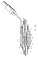
- FIG. 1 illustrates a preferred embodiment of the circulatory support system in accordance with the principles of the present disclosure.
- Particular features of support system 10 are also disclosed in U.S. Provisional Application Nos. 60/028,070 , 60/026,656 and 60/026,657, each filed October 4, 1996 , and each entitled CIRCULATORY SUPPORT SYSTEM, the contents of each being incorporated herein by reference.
- Circulatory support or bypass system 10 is contemplated to supplement or totally replace the pumping function of the heart during cardiac surgery and/or during temporary periods of heart failure.
- the system 10 can also be used during medical emergencies such as trauma, heart attack or heart failure.
- Circulatory support system 10 is particularly contemplated for patients in need of partial bypass of the left side of the heart while oxygenation of the blood may be maintained with the patient's own lungs.
- Support system 10 is advantageously arranged to be a portable unit which facilitates handling and reduces cost and incorporates a portable control unit discussed in greater detail below.
- support system 10 includes an axial flow pump 12 and inlet and outlet sections 14, 16 associated with the axial flow pump 12.
- Inlet and outlet sections 14, 16 will be discussed in greater detail below.
- axial flow pump 12 includes pump housing 18 composed of housing half sections 18a, 18b secured to each other with the use of adhesives, screws or the like.
- Inlet and outlet connectors 20, 22 are respectively mounted within inlet and outlet openings 24, 26 of pump housing 18. As can be seen, the inlet and outlet openings 24, 26 are in axial alignment although offset arrangements are envisioned as well.
- cylindrical mounting portions 20a, 22a of the respective connectors 20, 22 are positioned within sleeve 62 within the inlet and outlet openings 24, 26 of pump housing 18 and retained therein in a manner discussed in detail below.
- O-ring seals 28, 30 may be utilized to provide fluid tight seals between connectors 20, 22 and pump housing 18.
- Connectors 20, 22 respectively connect inlet and outlet cannulated tubes 14, 16 to flow pump 12.
- the length of the pump 10 ranges from about 3.0 inches to about 4.5 inches, more preferably, about 3.76 inches, and the diameter ranges from about 0.7 inches to about 2.0 inches, more preferably, about 1.2 inches. Other dimensions are contemplated which maintain the functionality and portability of the pump.
- inlet and outlet connectors 20, 22 include central interior hub portions 32, 34 respectively.
- Hub portion 32 of inlet connector 20 has inlet straightener blades 36 (e.g., 3) extending from the outer surface of the hub 32 to the inner surface of the connector 20 as also depicted in the cross-sectional view of FIG. 5 .
- hub portion 34 of outlet connector 22 has outlet straightener blades 38 extending from the outer surface of the hub 34 to the inner surface of the connector 22.
- Straightener blades 36 provide an axial flow effect on the blood entering flow pump to facilitate flow of the blood through the pump 12 to improve pump efficiency.
- straightener blades 38 provide an axial flow effect on the blood exiting pump 12 to facilitate blood flow through outflow cannulated tube 16 and within the circulating system of the patient.
- blades 36, 38 are not required and may be substituted with one or more support struts which have little or no affect on the blood flow and may function to support bearings on which the impeller rotates.
- outlet connector 22 has snap ring 40 mounted about its periphery and retained thereon by spring clip 42. Snap ring 40 functions to snap onto housing 18 to retain outlet connector 22 onto the housing. Similarly, a snap ring (not shown) may be utilized to retain inlet connector 20 on housing 18, or, in the alternative, the connectors 20, 22 may be mounted to the housing 18 with the use of adhesives or the like.
- pump housing 18 includes cylindrical stator housing 44 disposed in central portion 46 of the pump housing 18.
- Stator housing 44 may include four stator blades 48 attached to its interior wall.
- Stator blades 48 extend axially and also peripherally within the interior wall of stator housing 44 to define the generally serpentine configuration of the blades shown.
- Stator blades 48 provide a general axial flow type effect on the blood passing through pump housing 18.
- An impeller 50 extends through stator housing 44 and is mounted via rotating shaft 52 to interior hubs 32,34 of inlet and outlet connectors 20, 22, respectively. It is envisioned that bearings (e.g., sleeve) may be utilized to mount shaft 52. The bearings are preferably formed of polyethylene or the like. Impeller 50 has a plurality (e.g., 5) of impeller blades 54. Impeller blades 54 extend axially and circumferentially about the outer surface of the impeller 38 to provide an axial-flow pumping energy to blood entering pump housing. The outer surface of impeller 50 and the inner surface of stator housing 44 define an annular gap or blood path 56 through which blood passes through pump housing 18.
- Impeller 50 has a built-in 2-pole rotor magnet 58 as best depicted in FIG. 9 . Blood flowing through this gap washes the bearings at the junction between the rotating and stationary components to cool the bearings and prevent thrombosis, thus avoiding having to provide a seal. In a preferred method of manufacture, impeller 50 is molded about shaft 52.
- the motor includes a motor stator 60 and rotor magnet 58.
- Motor stator 60 includes laminations and windings disposed between a sleeve 62 coaxially mounted about stator housing 44, and the interior wall of pump housing 18.
- Motor stator 60 is electrically connected to an external energy source.
- Stator 60 provides the appropriate electromagnetic forces to rotate the rotor magnet 58 and impeller 50.
- Motor stator 60 preferably has an outer diameter of about .70 inches to about 2.0 inches and preferably about .97 inches, thereby keeping the overall size of pump 10 relatively small.
- pump housing 18, stator housing 44 and impeller 50 are fabricated from a polymeric material and formed by conventional injection molding techniques. In a preferred arrangement all blood contacting surfaces are coated with an anti-thrombotic agent to prevent thrombosis development.
- FIGS. 9A-9B illustrate an alternate embodiment of the axial flow pump of FIG. 1 .
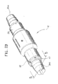
- this pump includes an aluminum cylindrical housing 18C which replaces pump housing half sections 18a, 18b and inlet and outlet end bells 20a, 22a which are mounted to respective end portions of the pump housing. End bells 20a, 22a support inlet and outlet connectors 20, 22.
- This motor also includes sleeve bearings 55 mounted within hub portions 32, 34 of the connectors 20, 22 to mount shaft 52 for rotational movement.
- a thrust rod 57 is disposed at least partially within inlet bearing 55 to accommodate thrust loads experienced during operation of the pump.
- Shaft 59 extends the length of impeller 50 and defines an enlarged tapered section 59a adjacent the outlet end of the pump.
- each section 14, 16 includes respective flexible tubes 66, 68 connected to inlet and outlet connectors 20, 22 of axial flow pump 12 by a friction fit.
- tubes 66, 68 preferably extend for a length of about 1-2 feet.
- Tubes 66, 68 may be spring reinforced to facilitate manipulation about the operative site.
- at least a portion of outlet tube 68 is compressible for reasons to be appreciated hereinbelow.
- Inlet and outlet cannulas 70, 72 are connected to the remote ends of flexible tubes 66, 68 through respective connectors 74, 76.
- Inlet cannula 70 has a blunt rounded end 78 for insertion into the patient's heart and a plurality of inflow ports 80 disposed in the side walls adjacent the blunt rounded end 78 to permit inflow of blood from the chamber of the heart.
- Outlet cannula 72 has an end 82 defining a bend therein which facilitates passage through a major vessel, e.g., aorta. End 82 may be straight as well. End 82 defines an outflow port 84(shown in phantom) to permit blood to exit the outflow tube 72 under pressure.
- Inlet and outlet cannula tubes 70, 72 are also preferably made of a flexible material.
- Connector 74 is a straight connector which retains inlet cannula 70 thereon by a friction fit.
- Connector 76 is a "T" connector having female threaded portion 89 to which is mounted stopcock valve 86.
- Stopcock valve 86 is a conventional valve having flow control handle 88 which rotates through manual manipulation to bleed or remove air from the system on the outlet side or section 16 of the system 10.
- the system 10 further includes pressure sensor plug 90 associated with inlet section 14.
- Pressure sensor plug 90 is electrically connected to cable 92 which extends toward the remote end of inlet cannula 70 to pressure transducer 94 mounted to the outer surface of the inlet cannula 70.
- Pressure transducer 94 is utilized to detect pressure within the heart chamber.
- the system 10 also includes pump control plug 96 which connects to the power source for energizing the pump 12.
- Control unit 100 functions in controlling and monitoring the operation of the assist system and for sounding audible alarms for various conditions such as the presence of air bubbles in the bloodstream, low blood flow rate, and so forth.
- Control unit 100 is preferably mobile to facilitate hospital use.
- the control unit 100 includes a monitor/control panel 102 which provides readouts of blood flow rate and pump speed.
- Panel 102 includes a large knob 109 to allow an operator to control motor speed and hence, blood flow rate.
- Panel 102 also includes light emitting diodes, each of which is lit when an associated alarm condition exists. Control buttons on the front panel enable the operator to control various functions such as re-starting the motor.
- the control unit also preferably has a rear display panel identical to that of the front panel for displaying the same information, so that the system parameter and alarm information is visible from the rear as well as from the front of the control unit.
- Blood flow rate is determined with a flowmeter/bubble detect sensor 104 clamped onto inflow tube 66.
- Sensor 104 shown schematically in FIG. 10 may be embodied as a conventional ultrasound flowmeter and bubble sensor packaged as a single unit.
- the electronics are shared between the flow sensing and bubble detection functions to minimize the electronics and size.
- flow sensing is accomplished conventionally by transmitting and receiving ultrasound signals diagonally across the cannula in both the upstream and downstream directions, and comparing the phase of the upstream and downstream signals to ascertain the flow rate.
- the bubble detection is based on a measurement of the amplitude of the received ultrasound wave relative to the transmitted wave. If the amplitude of the received signal suddenly drops below a threshold, then the presence of an air bubble is indicated.
- Output signals generated by sensor 104 indicative of the flow rate and of the presence of air bubbles in the system are relayed back to controller 100 via dedicated wires within harness 64. Operating voltage to sensor 104 is also provided on the wire harness.
- a suitable flowmeter/bubble detect sensor 104 is available commercially from Transonic Systems Inc., located in Ithica, NY, Model No. H9X197. As an alternative, the flow sensor and air bubble detectors may be embodied as separate units.
- a solenoid triggered cannula clamp 118 shown schematically in FIG. 10 is mounted on the output tube 68 of output section 68.
- controller 100 determines that the blood stream contains air bubbles, based on the output signals provided by sensor 104, it sends an actuating voltage on harness 64 to the clamp 118 to cause it to clamp down on the output tube 68 to crimp the tube and prevent air from entering the bloodstream.
- One suitable clamp is shown in FIG. 10A .
- the clamp (shown in exploded view) includes hollow cylinder 1000, left clamp 1002 pivotally mounted to the cylinder 1000 about pivot pin 1004 and defining clamping surface 1006, and latch pin 1008 which locks the left clamp 1002 in the open and closed position by reception within a corresponding opening (not shown) defined in the cylinder.
- a pair of finger grips 1010 and associated finger grip pins 1012 are mounted within respect to left clamp 1002. Finger grips 1010 and grip pins 1012 are depressed inwardly to release latch pin 1008 to permit opening of left clamp 1002 to position output tube 68 therein.
- the clamp further includes right clamp 1014 and retaining bar 1016 having distal bore 1018 to receive pin 1020 of right clamp 1014 to fixedly connect the two components.
- a link mechanism 1022 is mounted toward the proximal end of retaining bar 1016 and is fixed at its proximal end to retaining bar 1016 via pin A and at its distal end to stationary support plate 1024 via pin B.
- Support plate 1024 is mounted to the proximal end of cylinder 1000 and defines an axial opening to permit reciprocal movement of retaining bar 1016.
- a solenoid 1026 is mounted adjacent link mechanism 1022 and includes solenoid plunger 1028 which moves upwardly upon actuation to engage link mechanism 1022, more particularly, pin C of the link mechanism 1022, to actuate the link mechanism to drive retaining bar 1016 distally.
- the clamp further includes a handle mechanism 1030 which resets the link mechanism 1022 to its rest position.
- link mechanism 1022 is shown in the actuated position. Prior to actuation, the link mechanism 1022 is in an overtoggled position (where the links of the linkage mechanism are in linear alignment) with the plunger 1028 resting on pin C.
- wire harness 64 also included within wire harness 64 are wires that are routed to pressure sensor plug 90 ( FIG.1 ) which, in turn, is connected to wire 92 and pressure sensor 94 disposed at the distal end of inlet cannula 70, typically in proximity to the patient's heart. (The wires and sensor plug 90 are not shown in FIG. 10 for ease of illustration). These wires carry operating voltage to the pressure sensor 94 from control unit 100.
- the pressure sensor 94 provides an output signal representing the pressure sensed (also referred to herein interchangeably as "inlet pressure" of the pump 12). This output signal is routed to control unit 100 via wire harness "h". If inlet pressure is too low, motor speed is reduced to prevent suction occlusion.
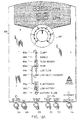
- control panel 102 of the control unit includes LEDs 108a to 108i arranged in a "traffic status board" type layout.
- Push-button switches 124-134 are located at the bottom of the panel.
- a large dial 109 is manually rotatable to set motor speed. Readouts of measured motor speed in revolutions per minute (RPM) and measured blood flow rate in liters per minute (LPM) are digitally displayed directly above the dial.
- RPM revolutions per minute
- LPM measured blood flow rate in liters per minute
- FIGS. 11B and 11C show respective front and rear perspective views of control unit 100.
- control unit 100 is embodied in the general shape of a long solid rectangle, with an exemplary height of about 48-50 inches, preferably, 54.5 inches, a width of about 7-12 inches, preferably, 9.7 inches, a thickness of only 3-7 inches, preferably, 5.5 inches, and with a suitable base support 112, preferably on wheels.
- control unit 100 is ergonomically designed to occupy a minimal amount of operating room space.
- the height of the display panel 102 relative to the base support is high enough to prevent obstruction of the panel by the patient lying on the adjacent operating table.
- Base support 112 has side portions 115 that are approximately flush with the sides 123 of the main rectangular body of the control unit to conserve space.
- the front and rear portions of the base support each protrude about six inches from the main rectangular body.
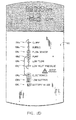
- a handle 113 is provided on the front portion of the solid rectangular body.
- a display panel 103 of preferably the same display format as the front panel 102 is provided on the rear of control unit 100, so that the alarm LEDs, motor speed and flow rate are visible from the rear as well as from the front of control unit 100. As such, visibility of the information by several personnel is facilitated.
- the motor speed control dial and push-button switches 124-134 are omitted from the rear display. Display panel 103 is shown in more detail in FIG. 11D .
- control unit 100 includes a Control central processor unit (CPU) core 150 which receives input signals from various circuit components within the control unit and within pump 12, and, in response, provides appropriate output signals to implement a host of functions.
- a Display CPU 160 acts as an interface between Control CPU core 150 and each of the push-button switches 124-132, LEDs 108(a-i) and the motor speed and flow rate displays.
- a Main Motor Controller/Driver 170 provides the drive power to motor 60 responsive to a pulse width modulated (PWM) signal from Control CPU core 150.
- PWM pulse width modulated
- a back-up Motor Controller/Driver 180 is provided to control the motor in a manual mode during emergency situations, for example.
- Control CPU core 150 A simplified block diagram of Control CPU core 150 is presented in FIG. 13 .
- a processor 202 such as Motorola MC 68332 communicates with the peripheral components such as Display CPU 160 by means of a Universal Asynchronous Receiver/Transmitter (UART) 204.
- Processor 202 contains a Time Processor Unit or PWM converter 212 which is used to generate a PWM signal for application to motor controller/driver 170 to control motor speed.
- a digital to analog (D/A) converter may be coupled to processor 202 and would provide an analog output voltage to control motor speed responsive to a digital word from processor 202.
- Control CPU core 150 and Driver CPU 160 are in constant communication via UART 204. (Display CPU 160 utilizes a similar UART therewithin).
- Control CPU core 150 Each time Control CPU core 150 sends a "display" message, the Display CPU responds with a "key” message to indicate the status of the key presses. Typically this "key” message will indicate that no keys have been pressed and imply that the previous message was received. All messages may contain a checksum such that exclusive-OR of all the bytes results in 0x00.
- the Control CPU core and Display CPU may communicate using standard communications protocols, e.g., at 9600 baud, with even parity, seven data bits, one stop bit and without handshaking lines.
- Control CPU 150 also includes SRAM 208, e.g., 256 Kbit or higher, which may be used to store measured data as well as for storing parameters during computations performed by processor 202. Processor 202 also retrieves various parameter information such as threshold data stored in optional EPROM 210 (e.g. 64 Kbit x 16) or within flash memory 206.
- optional EPROM 210 e.g. 64 Kbit x 16
- main power supply 172 switches AC line voltage to main power supply 172 as well as to back-up power supply 174, each of which rectify the AC to provide DC output voltages (e.g. 8-15V DC) for powering the various circuit components of the system.
- Main power supply 172 also supplies voltage to a battery charger circuit 171 which charges battery 176.
- a switch 179 detects voltage output from main power supply 172 and, if it is within a predetermined voltage range, switches this voltage to output line 187. If switch 179 detects that the voltage output from power supply 172 is out of range, it switches voltage from battery 176 to output line 187. In either case, the voltage output on line 187 is provided to a push-button controlled relay 134.
- switch 181 detects voltage from back-up power supply 174, and if this voltage is within the predetermined range, it switches the voltage to its output line 183. Otherwise, switch 181 switches the battery voltage from battery 176 to its output line 183. Switches 179 and 181 are preferably diode switches.
- Isolation power supply 190 includes a DC to DC converter to convert the voltage on line 207 (if present) to a higher voltage (e.g., 24V DC) to provide isolated power.
- the purpose of the isolated power is to diminish the possibility of electric shock to the patient undergoing treatment.
- the isolated power is supplied to the circuit components which are directly coupled to sensors which may contact the patient or the patient's blood.
- isolated power is supplied to Motor Controller/Driver 170, pressure transducer 94, flow rate/bubble sensor 104, cannula clamp 118, and optional motor speed sensor 61.
- the main power at the output of switch 134 is supplied to the remaining circuit components of the control unit.
- output voltage on line 203 is also provided to back-up isolation power supply 182, which provides back-up isolation power to back-up Motor Controller/Driver 180 and to the engage back-up switch 132.
- a multi-channel A/D converter 111 (e.g., eight channels) is coupled to the battery 176 and to output lines 203 and 207, and converts the respective voltages at those points to digital output signals which are supplied to CPU core 150. From the digital signal associated with the battery, CPU core 150 determines whether the battery voltage is below a predetermined threshold. If so, it commands Display CPU 160 to light the "Low Battery” LED on the display. CPU core 150 also determines from the digital outputs whether the battery is in use. If it is, CPU core 150 provides a corresponding alarm command to CPU 160, which then causes the "Battery in Use" LED 108i to light.
- A/D Converter 111 is also coupled to motor speed dial 109 and provides CPU core 150 with a digital output indicative of the dial position.
- CPU core 150 outputs a PWM signal S C (produced by the PWM converter therein) to Motor Controller/Driver 170 through opto-coupler array 175.
- This opto-coupler array is used for isolation purposes to prevent voltages from within CPU core 150 from accidentally causing electric shock to the patient. Other isolation techniques such as transformer-coupled isolation may alternatively be used.
- Motor Controller/Driver 170 includes processing and drive circuitry to vary the drive voltage provided to motor 60 on leads 64a responsive to the PWM of signal S C , in order to control motor speed and starting or stopping of the motor.
- Back-up Motor Controller/Driver 180 is utilized to drive the motor 60.
- the Back-up Controller/Driver 180 does not receive motor control signals from CPU core 150, but rather, it is directly coupled to the motor speed dial 109 and controls motor speed in accordance with the dial position.
- Switch 132 switches the voltage output from the appropriate Controller/Driver 170 or 180 to motor 60 via lines 64a.
- the "engage back-up" switch 132 is utilized when the operator desires to override the automatic control by the CPU core such that the motor speed is controlled manually. This manual operating mode is useful in emergency situations when the control unit cannot properly control blood flow under CPU core control.
- a feedback EMF signal from the motor coils is provided back to both Controller/Driver 170 on line 64b and to Controller/Driver 180.
- the processor within Controller/Driver 170 or 180 determines the actual motor speed based on the feedback EMF signal, compares the actual speed with the desired speed according to signal S C (or according to the dial 109 position directly when the back-up Controller/Driver 180 is in operation), and adjusts the drive voltage provided on lines 64a to obtain the desired speed within a predetermined tolerance.
- the actual measured motor speed is continually or periodically communicated by Controller/Driver 170 to the Control CPU core 150 as signal S F .
- Control CPU core 150 in turn transmits the motor speed information to Display CPU 160 to display the same on control panel 102.
- Both Controller/Drivers 170, 180 include a current limiting circuit which limits current drawn by motor 60 to a predetermined maximum. If the maximum current is reached, this is indicative of the motor 60 or pump 12 malfunctioning. When maximum current is reached, Motor Controller/Driver 170 forwards a signal S i back to the Control CPU core 150 indicative of this condition. CPU core 150 responds by sending a message to Display CPU 160 to light the "pump" LED 108d and sound an audible alarm. However, this condition does not stop the motor. (The Back-up Controller/Driver 180 may also be designed to communicate this information back to CPU core 150).
- Suitable controller chips which may be utilized within Controller/Drivers 170 and 180 to perform many of the above-described functions are commercially available from several manufacturers. Examples include U.S. Philips Corporation, located in Sunnyvale, CA (part No. Philips TDA-5140) or from Micro Linear Corporation, San Jose, CA (part No. Micro Linear 4425). Both of these controller chips operate as sensorless controllers which monitor the feed-back EMF from the motor coils to determine and control the motor speed. As an alternative, a controller used in conjunction with a motor speed sensor 61, e.g. a Hall effect sensor, could be employed. In this embodiment, feed-back EMF would not be used.
- a motor speed sensor 61 e.g. a Hall effect sensor
- Sensor 61 is positioned adjacent motor 60 and provides a signal S M indicative of the sensed motor speed on line 64c. This signal is routed to Motor Controller/Drive 170 (or 180) which derives the measured motor speed from the signal and then adjusts the voltage drive or pulse width modulation (PWM) signal to the motor accordingly to adjust motor speed. Signal S M is also provided to Control CPU 150 through opto-coupler 191 to enable the instantaneous motor speed to be displayed on the display panel as in the case above.
- Motor Controller/Drive 170 or 180
- PWM pulse width modulation
- flow rate/bubble sensor 104 provides measurement of blood flow rate and monitors for bubbles in the blood, preferably using ultrasound.
- This sensor provides measurement of blood flow rate and monitors for bubbles in the blood, preferably using ultrasound.
- the existence of any bubbles greater than a predetermined size can cause a serious medical condition since air is being pumped into the bloodstream.
- the pump is immediately caused to shut down to allow the surgeon to instantly remedy the bubble condition such as by sucking out the bubble with a syringe.
- control unit 100 sends a command to a clamp control circuit 222, which responds by providing an actuation voltage to the cannula clamp 118.
- the actuation voltage causes clamp 118 to clamp down on the output tube 68, thereby crimping the cannula or tube and preventing air bubbles from entering the patient's bloodstream.
- operating voltage is supplied to flow/bubble sensor 104 on line 64f.
- Sensor 104 outputs a flow rate signal S FR and a bubble sense signal S B on lines 64e corresponding to the associated conditions within inlet cannula 14.
- the sensor output signals are supplied to Flow Rate/Bubble Detect Circuit 140, e.g., a circuit board product available from Transonic Systems Inc., model T109 circuit board. Circuit 140 communicates the sensor output signals S B and S FR to Control CPU 150 in a suitable format, and also provides control signals to sensor 104 to control its operation.
- Control CPU 150 If signal S B indicates the presence of a bubble condition, Control CPU 150 immediately changes the voltage level of motor control signal S C (or transmits another signal) to command a shut-down of motor 60, whereby Motor Controller/Driver 170 causes motor 60 to cease rotation. Contemporaneously, Control CPU 150 sends a command signal to clamp control circuit 222 to initiate clamping by clamp 118 by providing a momentary actuation voltage thereto. An alarm signal is sent to Display CPU 160 which causes the "Bubble" LED 108b and the "re-start pump” LED 136 to light or blink. In addition, CPU 150 activates audible alarm circuit 184 by outputting a tone signal ST and a volume signal SV. The tone signal enables circuit 184 to produce audible output through speaker 164.
- the volume signal causes the audible output to be ramped up to avoid startling the surgeons/nurses.
- the audible alarm circuit 184 is automatically activated by CPU 150 whenever any of the other alarm LEDs 108a - 108i are lit.
- the "silence alarm” button 128 enables an operator to silence the audible alarm each time it occurs for any of the alarm conditions).
- the operator may attempt to remove the bubbles from the cannula such as by sucking them out with a syringe. Thereafter, to restart the pump, the operator manually resets the cannula clamp, and depresses the Restart pump button 130, which causes the bubble alarm to be extinguished and the motor to be re-started to a speed in accordance with the manual dial 109.
- the cannula clamp 118 and the associated clamp control circuit 222 are eliminated.
- a bubble alarm condition will still stop the motor as described above to permit the bubble condition to be remedied such as with a syringe.
- the motor will then be re-started only after the Re-start pump button 130 is manually activated.
- the flow rate signal S FR outputted by sensor 104 is routed to CPU 150 in suitable format by detect circuit 140.
- CPU 150 routes the flow rate information to Display CPU 160 which causes it to be displayed on the panel 102.
- Control CPU 150 performs a software routine wherein the flow rate is compared to a threshold value "L1" stored in memory within the CPU. If the flow rate drops below "L1" for a predefined time period, e.g., below 2 LPM for more than one second, CPU 150 communicates a message to CPU 160 to light the "Low Flow" alarm LED 108e and sound an audible alarm.
- control unit 100 also monitors for flow blockage and generates a flow blockage alarm via a dedicated LED (not shown) and audio alarm if blockage is detected.
- CPU 150 stores flow rate data continuously and evaluates whether the flow rate has dropped unexpectedly in the absence of the speed dial 109 being moved (after the flow rate having been above a predetermined threshold such as one LPM). If the flow rate drops by a predetermined amount or percent, e.g., by more than 30% in less than two seconds, then the flow blockage alarm is activated. The flow blockage alarm is extinguished when the flow rate rises above a threshold, e.g., above one LPM.
- Control unit 100 also communicates with pressure transducer 94 to ascertain the measured pressure in the transducer's location, e.g., in proximity to or within the atrium, or alternatively, within the inlet cannula in a position closer to pump 12.
- Pressure transducer 94 may be a conventional miniaturized transducer available commercially, e.g., from Ohmida Medical Devices, located in Madison, WI.
- transducer 94 is embodied within a housing clamped to the outer surface of the inlet cannula, e.g., in proximity to the pump.
- Pressure transducer 94 receives operating voltage via leads 64d (which run within the outer sheathing of inlet cannula 14) and outputs a signal SP indicative of the pressure back to the control unit on another one of leads 64d. This signal is digitized and received by opto-coupler 197 and routed through interface circuit 193 to CPU 150 in suitable format.
- CPU 150 includes a software routine that stores measured pressure data and determines whether the instantaneous pressure has dropped below a predetermined threshold "P1", e.g., to less than 2mm of mercury. If so, a message is outputted to CPU 160 to light the Low Inlet Pressure LED 108f.
- CPU 150 sends a command to Motor Controller/Driver 170 to automatically reduce the motor speed at a predetermined rate of reduction, in an attempt to automatically bring the pressure back.
- Motor speed continues to drop until the pressure rises above P 1 (or above a higher threshold) for more than a predetermined time period, e.g., for more than 1.2 seconds.
- motor speed is then ramped up to a speed in accordance with the speed dial 109.
- the motor speed is reduced to a predetermined speed, or by a predetermined amount, and is maintained at that lower speed until the pressure rises above a threshold, which is followed by motor speed ramp-up).
- control unit 100 may include means to manually calibrate or "zero" the pressure measurement. That is, when CPU 150 detects that the "Set Zero Pressure” push-button 124 on the panel is depressed, it reads the instantaneous value of pressure as outputted by transducer 94 and stores that value as the offset to be used whenever the pressure transducer is read.
- the pressure transducer is preferably zeroed in this manner by the operator each time the control unit is turned on and prior to the cannulas 14, 16 being attached to the patient.
- Control unit 100 preferably includes a test mode to verify proper operation of the motor.
- the test mode is activated by depression of "Test" push-button 126 on the panel, whereupon CPU 150 will send a command to Motor Controller/Driver 170 to force motor 60 to run for, e.g. 10-15 seconds at varying speeds.
- the motor will run regardless of any alarm conditions.
- the alarm LEDs will still light, but the alarms will not be audible or prevent the motor from running during the test mode.
- a Power On Self-test feature is provided whereby the control unit undergoes a self-test under the control of CPU 150 whenever power is initially turned on. If the CPU detects any error within itself or any of its peripherals, CPU 150 will not allow the unit to run.
- the self test preferably includes a RAM test to determine if the RAM is accessible and a ROM test to ascertain that the check sum of the code has not changed. A test for invalid readings from any sensor is also included, as well as a connectivity/continuity test and a display test. If there are any errors, the LED on the front panel corresponding to the faulty circuit component will be lit and all dashes displayed on the flow rate and motor speed displays. If there are no errors, none of the LEDs will be lit and all zeroes are preferably displayed on the flow rate and motor speed displays.
- the "flow sensor" LED 108c on the front panel is lit and an audible alarm is sounded if the flow sensor 104 is determined to be electrically disconnected from control unit 100, or if the bubble amplitude readings are below a predetermined threshold, indicating improper mounting or contact between the flow sensor and the tubing.
- the clamp control circuit 222 continually samples the continuity of the cannula clamp 118, and reports faults to the CPU 150.
- the "clamp" LED 108a is lit and an alarm sounded if continuity is deemed inadequate.
- the "electronics" LED 108g is lit and a buzzer activated if the control CPU 150 is not receiving adequate messages from the display CPU 160, or if any power supply voltages are out of specification.
- the control unit 100 also includes a connector (not shown) within the unit housing to enable connection to a personal computer (PC) to aid in the testing of the control unit. Communication with the PC may be transferred at, e.g., 9600 baud with no parity, eight data bits, one stop bit and without handshaking lines.
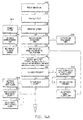
- step 302 Upon manual activation of the power switches (step 302) the Control CPU 150 performs the above-described self-test (step 307). If any errors are detected in step 308 the motor is disabled (step 309), the LED 108 on the panel associated with the faulty component will be lit (step 310) and the unit will be non-functional until the problem is corrected. Also, the motor speed and flow rate displays will show all dashes (step 311). If no errors are detected, the CPU core then determines in step 312 if the battery is in use or the battery is low, based on the digital outputs from A/D converter 111. If either condition is present, the corresponding LED is activated in step 313 by means of a command sent to Display CPU 160.
- CPU 150 determines the speed dial position in step 314 based on the output of converter 111, and forwards control signal S C to Motor Controller/Driver 170 to run the motor at the desired speed.
- bubble sense signal S B bubble sense signal S B
- flow rate signal S FR pressure sense signal S P
- motor speed sense signal S M motor speed sense signal S M (or S F )
- current limit signal Si are transmitted to CPU 150 by the respective circuit components as discussed above (step 316). These signals may be received by the UART within CPU 150 and stored in the SRAM and/or flash memory.
- the motor speed and flow rate are determined based on S M (or S F ) and S FR , respectively, and commands are sent to the Display CPU to display the same on the display panel.
- the Control CPU then evaluates the bubble signal S B (step 318). If a bubble is determined to be present, the motor is shut down and the bubble alarm activated (step 320). At this point the CPU core detects whether or not the Re-start button has been pressed in step 322. When it is depressed, the bubble alarm is de-activated (step 323) and the software flow returns to step 314 where the motor is started again.
- step 318 the next step is to ascertain whether the blood flow rate is less than the threshold level L1 (step 324). If so, the low flow rate alarm is activated in step 326. The alarm remains activated unless the flow rate rises above a threshold L2, e.g., 10% higher than L1 (steps 327, 329). The low flow rate condition does not stop the motor.
- a threshold L2 e.g. 10% higher than L1
- step 340 the CPU core evaluates whether the inlet pressure has dropped below the threshold P1 (in mm Hg). If it has, the low inlet pressure alarm is activated (step 342) and the motor speed is automatically reduced in step 344. The motor speed reduction is carried out at a predetermined rate of reduction. If the inlet pressure is still below P1 in step 345, then the flow returns to step 344 where the motor speed is reduced further. The motor speed is incrementally ramped down in this manner until the inlet pressure rises above P1. When it does rise above P1, the motor speed is maintained at the latest reduced speed in step 346. Then, in step 347, if the inlet pressure is above P1 for a specified time interval, e.g.
- step 349 the motor speed is ramped up in step 349. Otherwise, the flow returns to step 345. Once the motor speed is ramped up in step 349 to a speed in accordance with the motor speed dial 109, the pressure alarm is de-activated in step 350 and the flow returns to step 370.
- step 370 is to determine if the motor current is at the limit, based on the signal Si provided by the Motor Controller/Driver 170 or 180. If the limit is reached, the Pump alarm is turned on in step 375, otherwise, it is commanded off in step 380. The software flow then returns to step 312 where the diagnostic routine is repeated.
- support system 10 is illustrated for use with an open (full medial) sternotomy which involves the splitting of the sternum bone to gain access to the heart.
- support system 10 is contemplated for use in assisting the left side of the heart while the blood flows through the right side to deliver blood to the lungs for oxygenation.
- flow pump 12 of support system 10 is sufficiently small to be placed directly on the upper chest of the patient away from the sternal area and may be secured to the chest with conventional medical tape or secured to the drape with conventional surgical clips.
- Inflow and outflow sections 14, 16 are then appropriately positioned adjacent the chest cavity to access the heart and/or major blood vessels.
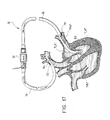
- Inlet cannula 70 of inlet section 14 is introduced through the heart wall and passed through the mitral valve "MV" with the inflow ports 80 positioned in the left ventricle “LV” as shown.
- Outlet cannula 72 is inserted through the aorta wall with the use of end portion 82 with the outflow port 84 positioned in a downstream position within the aorta "A”.
- blood is withdrawn from the left ventricle "LV” through inflow ports 80 of inflow cannula 70 and directed to the pump 12.
- Pump 12 imparts mechanical pumping energy to the blood and directs the blood under pressure through outflow cannula 72 and into the aorta "A", thus assisting the functioning of the left side of the heart.
- the blood is circulated throughout the body via the body's circulatory system and through the right side of the heart to the patient's lungs for oxygenation.
- monitoring, checking and controlling the system 10 is performed with control unit 100 to calculate flow rate, pressure within the heart, air bubble detection, etc... as discussed hereinabove.
- FIG. 16 illustrates an alternate method whereby the inflow cannula 70 accesses the "LV" through an incision formed in the wall of the heart.
- FIG. 17 illustrates another alternate method of application of circulatory support system 10.
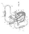
- inflow cannula 70 is introduced into the left ventricle “LV” through the region adjacent the juncture of the pulmonary veins "PV" (left or right) and passed through the mitral valve "MV" with the inflow ports 80 of the tube 70 located within the left ventricle "LV".
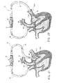
- FIG. 18 illustrates an alternate method of application where two support systems are used for total heart bypass.
- the support system utilized for bypass of the left side of the heart is identical to that described in connection with FIG. 15 .
- the support system utilized for right heart bypass has its inflow cannula 70 inserted through the heart wall with the inflow ports 80 positioned in the right ventricle "RV".
- the outflow cannula 72 is positioned in the pulmonary aorta "PA" in downstream orientation as shown.
- the lungs are still utilized to oxygenate the blood.
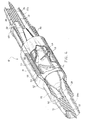
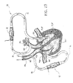
- FIGS. 19-20 illustrate yet another method of application of the circulatory support system.
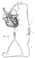
- inflow cannula 70 is percutaneously inserted through subclavian artery to the aorta "A" and advanced through the aortic valve "AV"' with the inflow ports 80 of the tube 14 positioned within the left ventricle "LV".
- Inflow cannula 70 has expandable membrane 98 (e.g., a balloon) positioned about its periphery to occlude the aorta "A”.
- a second catheter 99 (as shown) may be coaxially mounted about the cannula 70 to provide the inflation fluids to expand membrane 98 as is conventional in the art.
- the second catheter may include a connector 99a, e.g., a Luer connector, for providing the inflation fluids to be passed to membrane 98.
- inflow catheter 14 may have a separate lumen extending therethrough and terminating in a port 99b and port 99c to permit the introduction of cardioplegia solution within the heart to temporarily discontinue the pumping function of the heart, and/or for venting the left ventricle.
- Outflow cannula 70 is inserted, preferably, percutaneously within the femoral artery and advanced into the descending aorta "a".
- flexible membrane 98 is expanded to isolate the left side of the heart.
- the support system 10 is actuated to draw blood from the left ventricle "LV" through inflow ports 80 and into inflow cannula 70.
- the blood is directed through inflow cannula 70 and is subjected to the pumping energy of portable pump 12.
- the blood is returned through tube 68 and outflow cannula 72 and into the descending aorta "a".
- cardioplegia fluid or venting capabilities may be introduced via inflow catheter tube 14 and port 99b to be deposited from port 99c as described above.
- Inlet cannulated tube 14 is introduced through the heart wall with the inflow ports 80 positioned in the left atrium "LA” as shown.
- Outlet cannula 72 is inserted through the aorta wall with the use of end portion 82 with the outflow port 84 positioned in a downstream position within the aorta "A”.
- Blood is withdrawn from the left atrium "LA” through inflow ports 80 of inflow cannula 70 and directed to the pump 12.
- Pump 12 imparts mechanical pumping energy to the blood and directs the blood under pressure through outflow cannula 72 and into the aorta "A", thus assisting the functioning of the left side of the heart.
- the blood is circulated throughout the body via the body's circulatory system through the right side of the heart to the patient's lungs for oxygenation.
- FIG. 22 illustrates another alternate method of application of circulatory support system 10.
- inflow cannula 70 is introduced into the left atrium “LA” through the region of the juncture of the pulmonary veins "PV" with the inflow ports 80 of the cannula 70 located within the left atrium "LA”.
- FIG. 23 illustrates an alternate method of application where two support systems are used for total heart bypass.
- the support system utilized for bypass of the left side of the heart is identical to that described in connection with FIG. 21 .
- the support system utilized for right heart bypass has its inflow cannula 70 inserted through the heart wall with the inflow ports 80 positioned in the right atrium "RA",
- the outflow cannula 72 is positioned in the pulmonary aorta "PA" in downstream orientation as shown.
- the lungs are still utilized to oxygenate the blood.
- right bypass can be effectuated by accessing the right ventricle with inflow cannula 70
- left bypass can be effectuated by accessing the left ventricle with any of the arrangements described above.
- the circulatory support system 10 of the present disclosure provides for temporary short term heart support (either partial, e.g., left heart assist, or full support) of a patient.
- Set-up and management of the system requires relatively minimal effort.
- the entire system 10, i.e., the pump 12 including the motor 60 and associated tubing, can be manufactured cost effectively to be disposable.
- the features of the control unit, including the bubble detection, flow rate detection, automatic motor shutdown and clamping of the outlet cannula in case of detected bubble, various visible and audible alarms, and so forth, are particularly tailored to address the needs of an axial flow pump system.
- the control unit is also ergonomically designed to occupy a small amount of operating room space and to facilitate use in the operating room.
Landscapes
- Health & Medical Sciences (AREA)
- Heart & Thoracic Surgery (AREA)
- Cardiology (AREA)
- Engineering & Computer Science (AREA)
- Vascular Medicine (AREA)
- Veterinary Medicine (AREA)
- Biomedical Technology (AREA)
- Hematology (AREA)
- Life Sciences & Earth Sciences (AREA)
- Animal Behavior & Ethology (AREA)
- General Health & Medical Sciences (AREA)
- Public Health (AREA)
- Anesthesiology (AREA)
- Mechanical Engineering (AREA)
- Pulmonology (AREA)
- External Artificial Organs (AREA)
- Infusion, Injection, And Reservoir Apparatuses (AREA)
Abstract
Description
- The present disclosure relates generally to circulatory support systems, and, more particularly, to a circulatory support system to provide partial or total bypass of the heart. The present disclosure is further directed to an axial flow pump and a portable microprocessor-based controller each being adapted for use in the circulatory support system.
- Mechanical blood pumps are commonly utilized to temporarily support or substitute the pumping function of the heart during heart surgery or during periods of heart failure. The most widely applied blood pumps include roller pumps and centrifugal pumps. Typically, these pumps are a component of a cardiopulmonary bypass system (e.g., a heart-lung machine) which includes an oxygenator, a heat exchanger, blood reservoirs and filters, and tubing which transports the blood from the patient through the bypass system and back to the patient. With these systems, blood is withdrawn from the patient via uptake cannula positioned within the vena cavae and atria or ventricles of the heart and pumped back into the pulmonary artery and aorta via a return cannula.
- Although the aforedescribed cardiopulmonary bypass systems have been generally effective for their intended purposes, these systems are subject to certain disadvantages which detract from their usefulness. In particular, conventional bypass systems are relatively complicated and expensive to manufacture, expose the blood to a high surface area of foreign materials which may damage the blood, require full anticoagulation and cooling of the heart, and require considerable set up time and continual management by a skilled technician. These systems also require mechanical oxygenation of the blood which can have adverse affects on the patient.
-
U.S. Patent No. 4,610,656 to Mortensen/Mehealus Partnership discloses a semi-automatic heart-lung substitution system. The Mortensen '656 system includes a roller pump which pumps blood from the patient's right heart via a venous cannula to a membrane oxygenator connected at the output of the roller pump. From the oxygenator, the blood flows to a compliance reservoir which is connected to a pulsatile left heart pump. Blood is pumped by the pulsatile left heart pump through a filter and bubble trap and then returned to the patient's arterial system through an arterial cannula. The Mortensen '656 system, however, is also a relatively complex device including several pumps and an oxygenator and, consequently, requires attendance of skilled technicians for set-up and operation. - Accordingly, the present disclosure is directed to a circulatory support system to support the functioning of the heart. In a preferred embodiment, the support system includes an extracorporeal pump member having a pump housing dimensioned for positioning directly on or adjacent to the chest area of a patient and defining inlet and outlet ports, a rotating member rotatably mounted in the pump housing to impart mechanical energy to blood entering the inlet port and to direct the blood through the outlet port, an inlet cannulated tube connected to the inlet port of the pump housing and having an inlet open end portion dimensioned for insertion within the patient's heart whereby blood is drawn from the heart through the inlet cannulated tube and directed into the pump housing, and an outlet cannulated tube connected to the outlet port of the pump housing and having an outlet end portion dimensioned for insertion within a major blood vessel associated with the heart whereby blood exiting the outlet port of the pump housing is conveyed through the outlet cannulated tube into the major blood vessel for transfer by the arterial system of the patient.
- The support system is particularly contemplated for left heart bypass while the right heart functions to direct blood to the lungs. It is envisioned that the right heart may be slowed or even stopped while the support system is utilized for left heart bypass.
- A method for providing at least partial bypass of the heart to supplement the pumping function of the heart to thereby enable the surgeon to perform various surgical procedures thereon is also disclosed. The method includes the steps of providing a circulatory assist system having a portable extracorporeal axial flow pump with a pump housing and inlet and outlet ports, a rotating pumping member disposed in the pump housing and inlet and outlet cannulated tubes respectively connected to the inlet and outlet ports of the pump housing, accessing the patient's left ventricle of the heart with the inlet cannulated tube, accessing the aorta with the outlet cannulated tube, actuating the rotating pumping member to draw oxygenated blood from the left ventricle of the heart through the lumen of the inlet cannulated tube and into the inlet port of the pump housing whereby the pumping member imparts mechanical energy to the oxygenated blood passing through the pump housing and directs the oxygenated blood through the outlet port and through the lumen of the outlet cannulated tube to be transferred by the aorta to the systemic arteries, and permitting blood returning through the systemic veins to the right atrium to be directed through the right ventricle to the patient's lungs for oxygenation and subsequent pulmonary circulation. The left ventricle may be accessed through the heart wall, mitral valve or aortic valve. In an alternate embodiment, a second circulatory assist system may be utilized to facilitate the pumping function of the right side of the heart.
- The present disclosure is further directed to a pump to be used in the circulatory support system. The pump includes a pump housing including an inlet end portion defining an inlet port for permitting blood to enter the pump housing and an outlet end portion defining an outlet port for permitting blood to exit the pump housing. The inlet and outlet end portions preferably each have central hub portions with straightener blades extending therefrom for facilitating passage of blood through the pump housing. A rotatable member is mounted for rotational movement to the central hub portions of the pump housing. The rotatable member includes at least one impeller blade for imparting pump energy to blood passing through the pump housing and a magnetically actuated rotor. A motor stator is disposed in the pump housing and has at least one stator blade extending from an inner surface thereof. The one stator blade and the one impeller blade of the rotatable member are cooperatively configured to exert a substantially axial flow pumping energy to blood flowing along the blood path. Preferably, the one impeller blade and the one stator blade each extend axially and peripherally within the pump housing.
- The present disclosure is further directed to a control unit to be used in the circulatory support system. In an exemplary embodiment, the control unit includes circuitry for supplying power to the flow pump to cause the pump to rotate, and circuitry responsive to a pressure sense signal from a pressure transducer located on the inlet side of the pump (e.g., within the atrium), for commanding a reduction in motor speed to a lower speed when the pressure is determined to be below a predetermined threshold. The control unit preferably also includes circuitry responsive to a bubble sense signal provided by a bubble detector mounted to one of the cannulas, for generating a bubble alarm and for causing rotation of the pump to cease if the bubble sense signal indicates the presence of an air bubble. The control unit may further include circuitry responsive to the bubble sense signal indicating the presence of an air bubble for causing a clamping device mounted to one of the cannulas to clamp down on the cannula to prevent air from entering the patient's bloodstream.
- Preferred embodiment(s) of the present disclosure are described herein with reference to the drawings wherein:
-
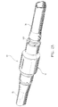
FIG. 1 is a side plan view of the circulatory support system of the present disclosure illustrating the portable pump and the pump inflow and outflow sections; -
FIG. 2A is a perspective view of the portable pump of the circulatory support system with inflow and outflow sections; -
FIG. 2B is a perspective view of the portable pump; -
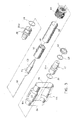
FIG. 3 is a perspective view with parts separated of the portable pump; -
FIG. 4 is a perspective view of the portable pump with portions cut away and in cross-section; -
FIG. 5 is a cross-sectional view taken along the lines 5-5 ofFIG. 2B illustrating the inlet straightener blades of the pump housing; -
FIG. 6 is a perspective view of the impeller and the stator housing of the portable pump; -
FIG. 7 is an axial view of the stator housing illustrating the arrangement of the stator blades; -
FIG. 8 is a cross-sectional view of the stator housing taken along the lines 8-8 ofFIG. 7 ; -
FIG. 9 is a cross-sectional view of the stator housing with mounted impeller; -
FIG. 9A is a cross-sectional view of an alternate portable pump to be used with the circulatory support system ofFIG. 1 ; -
FIG. 9B is a perspective view of the outer housing components of the pump ofFIG. 9A ; -
FIG. 10 is a view illustrating the system's control unit and use thereof in conjunction with supporting the pumping function of the heart of a patient; -
FIG. 10A is an exploded view of a clamp to be used with the control unit ofFIG. 10 ; -
FIG. 11A is an illustration of an exemplary front panel for a control unit controlling operation of the pump; -
FIG 11B is a perspective view of an exemplary control unit showing the front portion thereof; -
FIG. 11C is a perspective view of the exemplary control unit showing the rear portion thereof; -
FIG. 11D is an enlarged illustration of the rear panel shown inFIG. 11C ; -
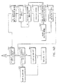
FIG. 12 is a block diagram illustrating the circuit components of the control unit and of the pump; -
FIG. 13 is a block diagram of an exemplary Control CPU used within the control unit; -
FIGS. 14A and14B are flow diagrams illustrative of a software routine running within the Control CPU; -
FIG. 15 is a view illustrating one method of application of the circulatory support system where the inlet cannula accesses the left ventricle of the heart through the mitral valve and the outlet cannula is disposed in the aorta; -
FIG. 16 is a view illustrating an alternate method of application of the circulatory support system where the inlet cannula accesses the left ventricle of the heart through the wall of the heart; -
FIG. 17 is a view illustrating another method of application of the circulatory support system where the inlet cannula accesses the left ventricle through the juncture of the pulmonary veins and through the mitral valve; -
FIG. 18 is a view illustrating the use of a second circulatory support system for assisting the right side of the heart; -
FIGS. 19-20 are views illustrating an alternative percutaneous method of application where the inlet cannula accesses the left ventricle through the aortic valve and the outlet cannula accesses the descending aorta through the femoral artery; -
FIG. 21 is a view illustrating another method of application of the circulatory support system where the inlet cannulated tube accesses the left atrium of the heart and the outlet cannulated tube is disposed in the aorta; -
FIG. 22 is a view illustrating another method of application of the circulatory support system where the inlet cannulated tube accesses the left atrium through the juncture of the pulmonary veins; and -
FIG. 23 is a view illustrating the use of a second circulatory support system for assisting the right side of the heart. - Referring now in detail to the drawings where like reference numerals identify similar or like components throughout the several views,
FIG. 1 illustrates a preferred embodiment of the circulatory support system in accordance with the principles of the present disclosure. Particular features ofsupport system 10 are also disclosed inU.S. Provisional Application Nos. 60/028,070 ,60/026,656 60/026,657, each filed October 4, 1996 - Circulatory support or
bypass system 10 is contemplated to supplement or totally replace the pumping function of the heart during cardiac surgery and/or during temporary periods of heart failure. Thesystem 10 can also be used during medical emergencies such as trauma, heart attack or heart failure.Circulatory support system 10 is particularly contemplated for patients in need of partial bypass of the left side of the heart while oxygenation of the blood may be maintained with the patient's own lungs.Support system 10 is advantageously arranged to be a portable unit which facilitates handling and reduces cost and incorporates a portable control unit discussed in greater detail below. - Referring now to
FIGS. 1-4 ,support system 10 includes anaxial flow pump 12 and inlet andoutlet sections axial flow pump 12. Inlet andoutlet sections FIGS. 3-4 ,axial flow pump 12 includespump housing 18 composed of housing half sections 18a, 18b secured to each other with the use of adhesives, screws or the like. Inlet andoutlet connectors outlet openings pump housing 18. As can be seen, the inlet andoutlet openings portions respective connectors sleeve 62 within the inlet andoutlet openings pump housing 18 and retained therein in a manner discussed in detail below. O-ring seals connectors housing 18.Connectors tubes pump 12. - In a preferred embodiment, the length of the
pump 10 ranges from about 3.0 inches to about 4.5 inches, more preferably, about 3.76 inches, and the diameter ranges from about 0.7 inches to about 2.0 inches, more preferably, about 1.2 inches. Other dimensions are contemplated which maintain the functionality and portability of the pump. - With particular reference to
FIG. 4 , inlet andoutlet connectors interior hub portions Hub portion 32 ofinlet connector 20 has inlet straightener blades 36 (e.g., 3) extending from the outer surface of thehub 32 to the inner surface of theconnector 20 as also depicted in the cross-sectional view ofFIG. 5 . Similarly,hub portion 34 ofoutlet connector 22 hasoutlet straightener blades 38 extending from the outer surface of thehub 34 to the inner surface of theconnector 22.Straightener blades 36 provide an axial flow effect on the blood entering flow pump to facilitate flow of the blood through thepump 12 to improve pump efficiency. Similarly,straightener blades 38 provide an axial flow effect on theblood exiting pump 12 to facilitate blood flow through outflow cannulatedtube 16 and within the circulating system of the patient. However,blades - As depicted in
FIGS. 1-4 ,outlet connector 22 hassnap ring 40 mounted about its periphery and retained thereon byspring clip 42.Snap ring 40 functions to snap ontohousing 18 to retainoutlet connector 22 onto the housing. Similarly, a snap ring (not shown) may be utilized to retaininlet connector 20 onhousing 18, or, in the alternative, theconnectors housing 18 with the use of adhesives or the like. - Referring now to
FIGS. 3 ,4 , and6-9 , pumphousing 18 includescylindrical stator housing 44 disposed incentral portion 46 of thepump housing 18.Stator housing 44 may include fourstator blades 48 attached to its interior wall.Stator blades 48 extend axially and also peripherally within the interior wall ofstator housing 44 to define the generally serpentine configuration of the blades shown.Stator blades 48 provide a general axial flow type effect on the blood passing throughpump housing 18. - An
impeller 50 extends throughstator housing 44 and is mounted via rotatingshaft 52 tointerior hubs outlet connectors shaft 52. The bearings are preferably formed of polyethylene or the like.Impeller 50 has a plurality (e.g., 5) ofimpeller blades 54.Impeller blades 54 extend axially and circumferentially about the outer surface of theimpeller 38 to provide an axial-flow pumping energy to blood entering pump housing. The outer surface ofimpeller 50 and the inner surface ofstator housing 44 define an annular gap orblood path 56 through which blood passes throughpump housing 18.Impeller 50 has a built-in 2-pole rotor magnet 58 as best depicted inFIG. 9 . Blood flowing through this gap washes the bearings at the junction between the rotating and stationary components to cool the bearings and prevent thrombosis, thus avoiding having to provide a seal. In a preferred method of manufacture,impeller 50 is molded aboutshaft 52. - With reference again to
FIGS. 3-4 and9 , the motor includes amotor stator 60 androtor magnet 58.Motor stator 60 includes laminations and windings disposed between asleeve 62 coaxially mounted aboutstator housing 44, and the interior wall ofpump housing 18.Motor stator 60 is electrically connected to an external energy source.Stator 60 provides the appropriate electromagnetic forces to rotate therotor magnet 58 andimpeller 50. Thus, due tohousing 44 andsleeve 62, the blood does not come into contact withmotor stator 60.Motor stator 60 preferably has an outer diameter of about .70 inches to about 2.0 inches and preferably about .97 inches, thereby keeping the overall size ofpump 10 relatively small. - Preferably, pump
housing 18,stator housing 44 andimpeller 50 are fabricated from a polymeric material and formed by conventional injection molding techniques. In a preferred arrangement all blood contacting surfaces are coated with an anti-thrombotic agent to prevent thrombosis development. -
FIGS. 9A-9B illustrate an alternate embodiment of the axial flow pump ofFIG. 1 . In accordance with this embodiment, most of the components including thestator housing 44,impeller 50, etc. are substantially similar or identical to the prior embodiment. However, this pump includes an aluminum cylindrical housing 18C which replaces pump housing half sections 18a, 18b and inlet andoutlet end bells End bells outlet connectors sleeve bearings 55 mounted withinhub portions connectors shaft 52 for rotational movement. Athrust rod 57 is disposed at least partially within inlet bearing 55 to accommodate thrust loads experienced during operation of the pump.Shaft 59 extends the length ofimpeller 50 and defines an enlargedtapered section 59a adjacent the outlet end of the pump. - With reference again to
FIG. 1 , inlet andoutlet sections section flexible tubes outlet connectors axial flow pump 12 by a friction fit. In one illustrative embodiment,tubes Tubes outlet tube 68 is compressible for reasons to be appreciated hereinbelow. - Inlet and outlet cannulas 70, 72 are connected to the remote ends of
flexible tubes respective connectors 74, 76.Inlet cannula 70 has a bluntrounded end 78 for insertion into the patient's heart and a plurality ofinflow ports 80 disposed in the side walls adjacent the bluntrounded end 78 to permit inflow of blood from the chamber of the heart.Outlet cannula 72 has anend 82 defining a bend therein which facilitates passage through a major vessel, e.g., aorta.End 82 may be straight as well.End 82 defines an outflow port 84(shown in phantom) to permit blood to exit theoutflow tube 72 under pressure. Inlet andoutlet cannula tubes - Connector 74 is a straight connector which retains
inlet cannula 70 thereon by a friction fit.Connector 76 is a "T" connector having female threaded portion 89 to which is mountedstopcock valve 86.Stopcock valve 86 is a conventional valve having flow control handle 88 which rotates through manual manipulation to bleed or remove air from the system on the outlet side orsection 16 of thesystem 10. - The
system 10 further includes pressure sensor plug 90 associated withinlet section 14. Pressure sensor plug 90 is electrically connected tocable 92 which extends toward the remote end ofinlet cannula 70 to pressuretransducer 94 mounted to the outer surface of theinlet cannula 70.Pressure transducer 94 is utilized to detect pressure within the heart chamber. - The
system 10 also includes pump control plug 96 which connects to the power source for energizing thepump 12. - Referring now to
FIG. 10 , a preferred control unit for use with thecirculatory support system 10 will be discussed.Control unit 100 functions in controlling and monitoring the operation of the assist system and for sounding audible alarms for various conditions such as the presence of air bubbles in the bloodstream, low blood flow rate, and so forth.Control unit 100 is preferably mobile to facilitate hospital use. Thecontrol unit 100 includes a monitor/control panel 102 which provides readouts of blood flow rate and pump speed.Panel 102 includes alarge knob 109 to allow an operator to control motor speed and hence, blood flow rate.Panel 102 also includes light emitting diodes, each of which is lit when an associated alarm condition exists. Control buttons on the front panel enable the operator to control various functions such as re-starting the motor. The control unit also preferably has a rear display panel identical to that of the front panel for displaying the same information, so that the system parameter and alarm information is visible from the rear as well as from the front of the control unit. - Blood flow rate is determined with a flowmeter/bubble detect
sensor 104 clamped ontoinflow tube 66.Sensor 104 shown schematically inFIG. 10 may be embodied as a conventional ultrasound flowmeter and bubble sensor packaged as a single unit. Preferably, the electronics are shared between the flow sensing and bubble detection functions to minimize the electronics and size. Generally, flow sensing is accomplished conventionally by transmitting and receiving ultrasound signals diagonally across the cannula in both the upstream and downstream directions, and comparing the phase of the upstream and downstream signals to ascertain the flow rate. The bubble detection is based on a measurement of the amplitude of the received ultrasound wave relative to the transmitted wave. If the amplitude of the received signal suddenly drops below a threshold, then the presence of an air bubble is indicated. Output signals generated bysensor 104 indicative of the flow rate and of the presence of air bubbles in the system are relayed back tocontroller 100 via dedicated wires withinharness 64. Operating voltage tosensor 104 is also provided on the wire harness. A suitable flowmeter/bubble detectsensor 104 is available commercially from Transonic Systems Inc., located in Ithica, NY, Model No. H9X197. As an alternative, the flow sensor and air bubble detectors may be embodied as separate units. - A solenoid triggered
cannula clamp 118 shown schematically inFIG. 10 is mounted on theoutput tube 68 ofoutput section 68. Whencontroller 100 determines that the blood stream contains air bubbles, based on the output signals provided bysensor 104, it sends an actuating voltage onharness 64 to theclamp 118 to cause it to clamp down on theoutput tube 68 to crimp the tube and prevent air from entering the bloodstream. One suitable clamp is shown inFIG. 10A . With reference to this Figure, the clamp (shown in exploded view) includeshollow cylinder 1000, leftclamp 1002 pivotally mounted to thecylinder 1000 aboutpivot pin 1004 and defining clamping surface 1006, andlatch pin 1008 which locks theleft clamp 1002 in the open and closed position by reception within a corresponding opening (not shown) defined in the cylinder. A pair offinger grips 1010 and associated finger grip pins 1012 are mounted within respect toleft clamp 1002. Finger grips 1010 andgrip pins 1012 are depressed inwardly to releaselatch pin 1008 to permit opening ofleft clamp 1002 to positionoutput tube 68 therein. The clamp further includesright clamp 1014 and retainingbar 1016 havingdistal bore 1018 to receivepin 1020 ofright clamp 1014 to fixedly connect the two components. Alink mechanism 1022 is mounted toward the proximal end of retainingbar 1016 and is fixed at its proximal end to retainingbar 1016 via pin A and at its distal end tostationary support plate 1024 via pin B. -
Support plate 1024 is mounted to the proximal end ofcylinder 1000 and defines an axial opening to permit reciprocal movement of retainingbar 1016. Asolenoid 1026 is mountedadjacent link mechanism 1022 and includessolenoid plunger 1028 which moves upwardly upon actuation to engagelink mechanism 1022, more particularly, pin C of thelink mechanism 1022, to actuate the link mechanism to drive retainingbar 1016 distally. The clamp further includes ahandle mechanism 1030 which resets thelink mechanism 1022 to its rest position. In the drawing,link mechanism 1022 is shown in the actuated position. Prior to actuation, thelink mechanism 1022 is in an overtoggled position (where the links of the linkage mechanism are in linear alignment) with theplunger 1028 resting on pin C. When a bubble is detected, the clamp is actuated which drivessolenoid plunger 1028 of thesolenoid 1026 upwardly, tripping thelink mechanism 1022 to the position shown inFIG. 10A . During movement to this position, link pin Adrives retaining bar 1016 andright clamp 1014 distally to thereby clamptube 68 betweenleft clamp 1002 and theright clamp 1014. To reset, thehandle mechanism 1030 is pulled rearwardly. As the retainingbar 1016 is pulled to the right, thelinkage mechanism 1022 will again over toggle ready to be tripped by the solenoid plunger. Another clamp suitable for this use is disclosed inU.S. Patent No. 4,524,802 to Lawrence , the contents of which are incorporated herein by reference. - Referring again to
FIG. 10 , also included withinwire harness 64 are wires that are routed to pressure sensor plug 90 (FIG.1 ) which, in turn, is connected to wire 92 andpressure sensor 94 disposed at the distal end ofinlet cannula 70, typically in proximity to the patient's heart. (The wires and sensor plug 90 are not shown inFIG. 10 for ease of illustration). These wires carry operating voltage to thepressure sensor 94 fromcontrol unit 100. Thepressure sensor 94 provides an output signal representing the pressure sensed (also referred to herein interchangeably as "inlet pressure" of the pump 12). This output signal is routed to controlunit 100 via wire harness "h". If inlet pressure is too low, motor speed is reduced to prevent suction occlusion. - With reference now to
FIGS. 11 (A-C) and 12, further details of the components ofcontrol unit 100 will be discussed. As shown inFIG. 11A ,control panel 102 of the control unit includesLEDs 108a to 108i arranged in a "traffic status board" type layout. Push-button switches 124-134 are located at the bottom of the panel. Alarge dial 109 is manually rotatable to set motor speed. Readouts of measured motor speed in revolutions per minute (RPM) and measured blood flow rate in liters per minute (LPM) are digitally displayed directly above the dial. -
FIGS. 11B and 11C show respective front and rear perspective views ofcontrol unit 100. Unlike conventional hospital equipment,control unit 100 is embodied in the general shape of a long solid rectangle, with an exemplary height of about 48-50 inches, preferably, 54.5 inches, a width of about 7-12 inches, preferably, 9.7 inches, a thickness of only 3-7 inches, preferably, 5.5 inches, and with asuitable base support 112, preferably on wheels. Hence,control unit 100 is ergonomically designed to occupy a minimal amount of operating room space. Also, the height of thedisplay panel 102 relative to the base support is high enough to prevent obstruction of the panel by the patient lying on the adjacent operating table.Base support 112 hasside portions 115 that are approximately flush with thesides 123 of the main rectangular body of the control unit to conserve space. The front and rear portions of the base support each protrude about six inches from the main rectangular body. Ahandle 113 is provided on the front portion of the solid rectangular body. - A
display panel 103 of preferably the same display format as thefront panel 102 is provided on the rear ofcontrol unit 100, so that the alarm LEDs, motor speed and flow rate are visible from the rear as well as from the front ofcontrol unit 100. As such, visibility of the information by several personnel is facilitated. The motor speed control dial and push-button switches 124-134 are omitted from the rear display.Display panel 103 is shown in more detail inFIG. 11D . - Referring to
FIG. 12 ,control unit 100 includes a Control central processor unit (CPU)core 150 which receives input signals from various circuit components within the control unit and withinpump 12, and, in response, provides appropriate output signals to implement a host of functions. ADisplay CPU 160 acts as an interface betweenControl CPU core 150 and each of the push-button switches 124-132, LEDs 108(a-i) and the motor speed and flow rate displays. A Main Motor Controller/Driver 170 provides the drive power tomotor 60 responsive to a pulse width modulated (PWM) signal fromControl CPU core 150. A back-up Motor Controller/Driver 180 is provided to control the motor in a manual mode during emergency situations, for example. - A simplified block diagram of
Control CPU core 150 is presented inFIG. 13 . Aprocessor 202 such as Motorola MC 68332 communicates with the peripheral components such asDisplay CPU 160 by means of a Universal Asynchronous Receiver/Transmitter (UART) 204.Processor 202 contains a Time Processor Unit orPWM converter 212 which is used to generate a PWM signal for application to motor controller/driver 170 to control motor speed. Alternatively, a digital to analog (D/A) converter may be coupled toprocessor 202 and would provide an analog output voltage to control motor speed responsive to a digital word fromprocessor 202.Control CPU core 150 andDriver CPU 160 are in constant communication viaUART 204. (Display CPU 160 utilizes a similar UART therewithin). Each timeControl CPU core 150 sends a "display" message, the Display CPU responds with a "key" message to indicate the status of the key presses. Typically this "key" message will indicate that no keys have been pressed and imply that the previous message was received. All messages may contain a checksum such that exclusive-OR of all the bytes results in 0x00. The Control CPU core and Display CPU may communicate using standard communications protocols, e.g., at 9600 baud, with even parity, seven data bits, one stop bit and without handshaking lines.Control CPU 150 also includesSRAM 208, e.g., 256 Kbit or higher, which may be used to store measured data as well as for storing parameters during computations performed byprocessor 202.Processor 202 also retrieves various parameter information such as threshold data stored in optional EPROM 210 (e.g. 64 Kbit x 16) or withinflash memory 206. - In operation, referring again to
FIG. 12 , depression ofAC power switch 137 switches AC line voltage tomain power supply 172 as well as to back-uppower supply 174, each of which rectify the AC to provide DC output voltages (e.g. 8-15V DC) for powering the various circuit components of the system.Main power supply 172 also supplies voltage to abattery charger circuit 171 which chargesbattery 176. Aswitch 179 detects voltage output frommain power supply 172 and, if it is within a predetermined voltage range, switches this voltage tooutput line 187. Ifswitch 179 detects that the voltage output frompower supply 172 is out of range, it switches voltage frombattery 176 tooutput line 187. In either case, the voltage output online 187 is provided to a push-button controlledrelay 134. Likewise,switch 181 detects voltage from back-uppower supply 174, and if this voltage is within the predetermined range, it switches the voltage to itsoutput line 183. Otherwise, switch 181 switches the battery voltage frombattery 176 to itsoutput line 183.Switches - When
relay 134 is activated, the DC voltages onlines respective output lines CPU core 150 andCPU 160 and other circuit components ofcontrol unit 100. Each circuit component receiving main power will utilize the operating voltage from eitherline -
Isolation power supply 190 includes a DC to DC converter to convert the voltage on line 207 (if present) to a higher voltage (e.g., 24V DC) to provide isolated power. The purpose of the isolated power is to diminish the possibility of electric shock to the patient undergoing treatment. As such, the isolated power is supplied to the circuit components which are directly coupled to sensors which may contact the patient or the patient's blood. Hence, isolated power is supplied to Motor Controller/Driver 170,pressure transducer 94, flow rate/bubble sensor 104,cannula clamp 118, and optional motor speed sensor 61. The main power at the output ofswitch 134 is supplied to the remaining circuit components of the control unit. - When
relay 134 is activated, output voltage online 203 is also provided to back-upisolation power supply 182, which provides back-up isolation power to back-up Motor Controller/Driver 180 and to the engage back-upswitch 132. - A multi-channel A/D converter 111 (e.g., eight channels) is coupled to the
battery 176 and tooutput lines CPU core 150. From the digital signal associated with the battery,CPU core 150 determines whether the battery voltage is below a predetermined threshold. If so, it commandsDisplay CPU 160 to light the "Low Battery" LED on the display.CPU core 150 also determines from the digital outputs whether the battery is in use. If it is,CPU core 150 provides a corresponding alarm command toCPU 160, which then causes the "Battery in Use" LED 108i to light. - A/D Converter 111 is also coupled to
motor speed dial 109 and providesCPU core 150 with a digital output indicative of the dial position. In response,CPU core 150 outputs a PWM signal SC (produced by the PWM converter therein) to Motor Controller/Driver 170 through opto-coupler array 175. This opto-coupler array is used for isolation purposes to prevent voltages from withinCPU core 150 from accidentally causing electric shock to the patient. Other isolation techniques such as transformer-coupled isolation may alternatively be used. Motor Controller/Driver 170 includes processing and drive circuitry to vary the drive voltage provided tomotor 60 onleads 64a responsive to the PWM of signal SC, in order to control motor speed and starting or stopping of the motor. - If the "engage back-up"
switch 132 is depressed, then Back-up Motor Controller/Driver 180 is utilized to drive themotor 60. The Back-up Controller/Driver 180 does not receive motor control signals fromCPU core 150, but rather, it is directly coupled to themotor speed dial 109 and controls motor speed in accordance with the dial position. Switch 132 switches the voltage output from the appropriate Controller/Driver motor 60 vialines 64a. Thus, the "engage back-up"switch 132 is utilized when the operator desires to override the automatic control by the CPU core such that the motor speed is controlled manually. This manual operating mode is useful in emergency situations when the control unit cannot properly control blood flow under CPU core control. - A feedback EMF signal from the motor coils is provided back to both Controller/
Driver 170 on line 64b and to Controller/Driver 180. The processor within Controller/Driver dial 109 position directly when the back-up Controller/Driver 180 is in operation), and adjusts the drive voltage provided onlines 64a to obtain the desired speed within a predetermined tolerance. The actual measured motor speed is continually or periodically communicated by Controller/Driver 170 to theControl CPU core 150 as signal SF.Control CPU core 150 in turn transmits the motor speed information to DisplayCPU 160 to display the same oncontrol panel 102. - Both Controller/
Drivers motor 60 to a predetermined maximum. If the maximum current is reached, this is indicative of themotor 60 or pump 12 malfunctioning. When maximum current is reached, Motor Controller/Driver 170 forwards a signal Si back to theControl CPU core 150 indicative of this condition.CPU core 150 responds by sending a message to DisplayCPU 160 to light the "pump"LED 108d and sound an audible alarm. However, this condition does not stop the motor. (The Back-up Controller/Driver 180 may also be designed to communicate this information back to CPU core 150). - Suitable controller chips which may be utilized within Controller/
Drivers adjacent motor 60 and provides a signal SM indicative of the sensed motor speed online 64c. This signal is routed to Motor Controller/Drive 170 (or 180) which derives the measured motor speed from the signal and then adjusts the voltage drive or pulse width modulation (PWM) signal to the motor accordingly to adjust motor speed. Signal SM is also provided toControl CPU 150 through opto-coupler 191 to enable the instantaneous motor speed to be displayed on the display panel as in the case above. - Attention is now turned to flow rate/
bubble sensor 104. As discussed above, this sensor provides measurement of blood flow rate and monitors for bubbles in the blood, preferably using ultrasound. The existence of any bubbles greater than a predetermined size can cause a serious medical condition since air is being pumped into the bloodstream. Hence it is desirable for the operator/surgeon to be immediately apprised of a bubble condition whereupon it can be effectively remedied as soon as possible. In accordance with the present disclosure, if a bubble condition is sensed, the pump is immediately caused to shut down to allow the surgeon to instantly remedy the bubble condition such as by sucking out the bubble with a syringe. Following motor shut-down due to a bubble condition, the motor does not start again automatically, but must be manually restarted by depressing therestart pump button 130. In addition, immediately upon the detection of a bubble condition,control unit 100 sends a command to aclamp control circuit 222, which responds by providing an actuation voltage to thecannula clamp 118. The actuation voltage causes clamp 118 to clamp down on theoutput tube 68, thereby crimping the cannula or tube and preventing air bubbles from entering the patient's bloodstream. - In operation, operating voltage is supplied to flow/
bubble sensor 104 on line 64f.Sensor 104 outputs a flow rate signal SFR and a bubble sense signal SB onlines 64e corresponding to the associated conditions withininlet cannula 14. The sensor output signals are supplied to Flow Rate/Bubble DetectCircuit 140, e.g., a circuit board product available from Transonic Systems Inc., model T109 circuit board.Circuit 140 communicates the sensor output signals SB and SFR toControl CPU 150 in a suitable format, and also provides control signals tosensor 104 to control its operation. - If signal SB indicates the presence of a bubble condition,
Control CPU 150 immediately changes the voltage level of motor control signal SC (or transmits another signal) to command a shut-down ofmotor 60, whereby Motor Controller/Driver 170 causesmotor 60 to cease rotation. Contemporaneously,Control CPU 150 sends a command signal to clampcontrol circuit 222 to initiate clamping byclamp 118 by providing a momentary actuation voltage thereto. An alarm signal is sent toDisplay CPU 160 which causes the "Bubble" LED 108b and the "re-start pump"LED 136 to light or blink. In addition,CPU 150 activatesaudible alarm circuit 184 by outputting a tone signal ST and a volume signal SV. The tone signal enablescircuit 184 to produce audible output throughspeaker 164. The volume signal causes the audible output to be ramped up to avoid startling the surgeons/nurses. (It is noted here that theaudible alarm circuit 184 is automatically activated byCPU 150 whenever any of theother alarm LEDs 108a - 108i are lit. The "silence alarm"button 128 enables an operator to silence the audible alarm each time it occurs for any of the alarm conditions). - When the motor is shut down in correspondence with the bubble alarm, the operator may attempt to remove the bubbles from the cannula such as by sucking them out with a syringe. Thereafter, to restart the pump, the operator manually resets the cannula clamp, and depresses the
Restart pump button 130, which causes the bubble alarm to be extinguished and the motor to be re-started to a speed in accordance with themanual dial 109. - In an alternative embodiment, the
cannula clamp 118 and the associatedclamp control circuit 222 are eliminated. In this case, a bubble alarm condition will still stop the motor as described above to permit the bubble condition to be remedied such as with a syringe. The motor will then be re-started only after theRe-start pump button 130 is manually activated. - The flow rate signal SFR outputted by
sensor 104 is routed toCPU 150 in suitable format by detectcircuit 140.CPU 150 routes the flow rate information to DisplayCPU 160 which causes it to be displayed on thepanel 102.Control CPU 150 performs a software routine wherein the flow rate is compared to a threshold value "L1" stored in memory within the CPU. If the flow rate drops below "L1" for a predefined time period, e.g., below 2 LPM for more than one second,CPU 150 communicates a message toCPU 160 to light the "Low Flow"alarm LED 108e and sound an audible alarm. - Optionally,
control unit 100 also monitors for flow blockage and generates a flow blockage alarm via a dedicated LED (not shown) and audio alarm if blockage is detected. In this case,CPU 150 stores flow rate data continuously and evaluates whether the flow rate has dropped unexpectedly in the absence of thespeed dial 109 being moved (after the flow rate having been above a predetermined threshold such as one LPM). If the flow rate drops by a predetermined amount or percent, e.g., by more than 30% in less than two seconds, then the flow blockage alarm is activated. The flow blockage alarm is extinguished when the flow rate rises above a threshold, e.g., above one LPM. -
Control unit 100 also communicates withpressure transducer 94 to ascertain the measured pressure in the transducer's location, e.g., in proximity to or within the atrium, or alternatively, within the inlet cannula in a position closer to pump 12.Pressure transducer 94 may be a conventional miniaturized transducer available commercially, e.g., from Ohmida Medical Devices, located in Madison, WI. Alternatively,transducer 94 is embodied within a housing clamped to the outer surface of the inlet cannula, e.g., in proximity to the pump.Pressure transducer 94 receives operating voltage vialeads 64d (which run within the outer sheathing of inlet cannula 14) and outputs a signal SP indicative of the pressure back to the control unit on another one ofleads 64d. This signal is digitized and received by opto-coupler 197 and routed throughinterface circuit 193 toCPU 150 in suitable format.CPU 150 includes a software routine that stores measured pressure data and determines whether the instantaneous pressure has dropped below a predetermined threshold "P1", e.g., to less than 2mm of mercury. If so, a message is outputted toCPU 160 to light the LowInlet Pressure LED 108f. Contemporaneously,CPU 150 sends a command to Motor Controller/Driver 170 to automatically reduce the motor speed at a predetermined rate of reduction, in an attempt to automatically bring the pressure back. Motor speed continues to drop until the pressure rises above P 1 (or above a higher threshold) for more than a predetermined time period, e.g., for more than 1.2 seconds. When this condition is satisfied, motor speed is then ramped up to a speed in accordance with thespeed dial 109. (As an alternative, the motor speed is reduced to a predetermined speed, or by a predetermined amount, and is maintained at that lower speed until the pressure rises above a threshold, which is followed by motor speed ramp-up). - It is noted that
control unit 100 may include means to manually calibrate or "zero" the pressure measurement. That is, whenCPU 150 detects that the "Set Zero Pressure" push-button 124 on the panel is depressed, it reads the instantaneous value of pressure as outputted bytransducer 94 and stores that value as the offset to be used whenever the pressure transducer is read. The pressure transducer is preferably zeroed in this manner by the operator each time the control unit is turned on and prior to thecannulas -
Control unit 100 preferably includes a test mode to verify proper operation of the motor. The test mode is activated by depression of "Test" push-button 126 on the panel, whereuponCPU 150 will send a command to Motor Controller/Driver 170 to forcemotor 60 to run for, e.g. 10-15 seconds at varying speeds. In the test mode, the motor will run regardless of any alarm conditions. The alarm LEDs will still light, but the alarms will not be audible or prevent the motor from running during the test mode. - In addition, a Power On Self-test feature is provided whereby the control unit undergoes a self-test under the control of
CPU 150 whenever power is initially turned on. If the CPU detects any error within itself or any of its peripherals,CPU 150 will not allow the unit to run. The self test preferably includes a RAM test to determine if the RAM is accessible and a ROM test to ascertain that the check sum of the code has not changed. A test for invalid readings from any sensor is also included, as well as a connectivity/continuity test and a display test. If there are any errors, the LED on the front panel corresponding to the faulty circuit component will be lit and all dashes displayed on the flow rate and motor speed displays. If there are no errors, none of the LEDs will be lit and all zeroes are preferably displayed on the flow rate and motor speed displays. - During system operation, checks are continually performed on various components to verify proper continuity and operation, and an alarm is generated if a fault is detected. For instance, the "flow sensor"
LED 108c on the front panel is lit and an audible alarm is sounded if theflow sensor 104 is determined to be electrically disconnected fromcontrol unit 100, or if the bubble amplitude readings are below a predetermined threshold, indicating improper mounting or contact between the flow sensor and the tubing. Theclamp control circuit 222 continually samples the continuity of thecannula clamp 118, and reports faults to theCPU 150. The "clamp"LED 108a is lit and an alarm sounded if continuity is deemed inadequate. The "electronics"LED 108g is lit and a buzzer activated if thecontrol CPU 150 is not receiving adequate messages from thedisplay CPU 160, or if any power supply voltages are out of specification. Thecontrol unit 100 also includes a connector (not shown) within the unit housing to enable connection to a personal computer (PC) to aid in the testing of the control unit. Communication with the PC may be transferred at, e.g., 9600 baud with no parity, eight data bits, one stop bit and without handshaking lines. - Referring now to
FIGS. 14A and14B , a simplified flow diagram illustrating operation of a software routine running onControl CPU core 150 is presented. Upon manual activation of the power switches (step 302) theControl CPU 150 performs the above-described self-test (step 307). If any errors are detected instep 308 the motor is disabled (step 309), theLED 108 on the panel associated with the faulty component will be lit (step 310) and the unit will be non-functional until the problem is corrected. Also, the motor speed and flow rate displays will show all dashes (step 311). If no errors are detected, the CPU core then determines instep 312 if the battery is in use or the battery is low, based on the digital outputs from A/D converter 111. If either condition is present, the corresponding LED is activated instep 313 by means of a command sent toDisplay CPU 160. - Next,
CPU 150 determines the speed dial position instep 314 based on the output of converter 111, and forwards control signal SC to Motor Controller/Driver 170 to run the motor at the desired speed. With the motor running, bubble sense signal SB, flow rate signal SFR, pressure sense signal SP, motor speed sense signal SM (or SF) and current limit signal Si are transmitted toCPU 150 by the respective circuit components as discussed above (step 316). These signals may be received by the UART withinCPU 150 and stored in the SRAM and/or flash memory. The motor speed and flow rate are determined based on SM (or SF) and SFR, respectively, and commands are sent to the Display CPU to display the same on the display panel. The Control CPU then evaluates the bubble signal SB (step 318). If a bubble is determined to be present, the motor is shut down and the bubble alarm activated (step 320). At this point the CPU core detects whether or not the Re-start button has been pressed instep 322. When it is depressed, the bubble alarm is de-activated (step 323) and the software flow returns to step 314 where the motor is started again. - If in
step 318 there is no bubble detected greater than a predetermined size, the next step is to ascertain whether the blood flow rate is less than the threshold level L1 (step 324). If so, the low flow rate alarm is activated instep 326. The alarm remains activated unless the flow rate rises above a threshold L2, e.g., 10% higher than L1 (steps 327, 329). The low flow rate condition does not stop the motor. - Next, in step 340 (
FIG. 14B ) the CPU core evaluates whether the inlet pressure has dropped below the threshold P1 (in mm Hg). If it has, the low inlet pressure alarm is activated (step 342) and the motor speed is automatically reduced in step 344. The motor speed reduction is carried out at a predetermined rate of reduction. If the inlet pressure is still below P1 instep 345, then the flow returns to step 344 where the motor speed is reduced further. The motor speed is incrementally ramped down in this manner until the inlet pressure rises above P1. When it does rise above P1, the motor speed is maintained at the latest reduced speed instep 346. Then, instep 347, if the inlet pressure is above P1 for a specified time interval, e.g. for 1.2 seconds, the motor speed is ramped up instep 349. Otherwise, the flow returns to step 345. Once the motor speed is ramped up instep 349 to a speed in accordance with themotor speed dial 109, the pressure alarm is de-activated instep 350 and the flow returns to step 370. - The next step (step 370) is to determine if the motor current is at the limit, based on the signal Si provided by the Motor Controller/
Driver step 375, otherwise, it is commanded off instep 380. The software flow then returns to step 312 where the diagnostic routine is repeated. - Preferred arrangements for connecting the
support system 10 will now be discussed. With reference again toFIG. 10 ,support system 10 is illustrated for use with an open (full medial) sternotomy which involves the splitting of the sternum bone to gain access to the heart. As discussed above,support system 10 is contemplated for use in assisting the left side of the heart while the blood flows through the right side to deliver blood to the lungs for oxygenation. As depicted, flow pump 12 ofsupport system 10 is sufficiently small to be placed directly on the upper chest of the patient away from the sternal area and may be secured to the chest with conventional medical tape or secured to the drape with conventional surgical clips. Inflow andoutflow sections FIG. 15 , one arrangement for connecting the system is described.Inlet cannula 70 ofinlet section 14 is introduced through the heart wall and passed through the mitral valve "MV" with theinflow ports 80 positioned in the left ventricle "LV" as shown.Outlet cannula 72 is inserted through the aorta wall with the use ofend portion 82 with theoutflow port 84 positioned in a downstream position within the aorta "A". Upon operation of thesystem 10, blood is withdrawn from the left ventricle "LV" throughinflow ports 80 ofinflow cannula 70 and directed to thepump 12.Pump 12 imparts mechanical pumping energy to the blood and directs the blood under pressure throughoutflow cannula 72 and into the aorta "A", thus assisting the functioning of the left side of the heart. The blood is circulated throughout the body via the body's circulatory system and through the right side of the heart to the patient's lungs for oxygenation. During operation, monitoring, checking and controlling thesystem 10 is performed withcontrol unit 100 to calculate flow rate, pressure within the heart, air bubble detection, etc... as discussed hereinabove. -
FIG. 16 illustrates an alternate method whereby theinflow cannula 70 accesses the "LV" through an incision formed in the wall of the heart. -
FIG. 17 illustrates another alternate method of application ofcirculatory support system 10. In accordance with this method of application,inflow cannula 70 is introduced into the left ventricle "LV" through the region adjacent the juncture of the pulmonary veins "PV" (left or right) and passed through the mitral valve "MV" with theinflow ports 80 of thetube 70 located within the left ventricle "LV". -
FIG. 18 illustrates an alternate method of application where two support systems are used for total heart bypass. The support system utilized for bypass of the left side of the heart is identical to that described in connection withFIG. 15 . The support system utilized for right heart bypass has itsinflow cannula 70 inserted through the heart wall with theinflow ports 80 positioned in the right ventricle "RV". Theoutflow cannula 72 is positioned in the pulmonary aorta "PA" in downstream orientation as shown. In this application, the lungs are still utilized to oxygenate the blood. -
FIGS. 19-20 illustrate yet another method of application of the circulatory support system. In accordance with this percutaneous approach,inflow cannula 70 is percutaneously inserted through subclavian artery to the aorta "A" and advanced through the aortic valve "AV"' with theinflow ports 80 of thetube 14 positioned within the left ventricle "LV".Inflow cannula 70 has expandable membrane 98 (e.g., a balloon) positioned about its periphery to occlude the aorta "A". A second catheter 99 (as shown) may be coaxially mounted about thecannula 70 to provide the inflation fluids to expandmembrane 98 as is conventional in the art. The second catheter may include a connector 99a, e.g., a Luer connector, for providing the inflation fluids to be passed tomembrane 98. It is also envisioned thatinflow catheter 14 may have a separate lumen extending therethrough and terminating in a port 99b and port 99c to permit the introduction of cardioplegia solution within the heart to temporarily discontinue the pumping function of the heart, and/or for venting the left ventricle.Outflow cannula 70 is inserted, preferably, percutaneously within the femoral artery and advanced into the descending aorta "a". - In application,
flexible membrane 98 is expanded to isolate the left side of the heart. Thesupport system 10 is actuated to draw blood from the left ventricle "LV" throughinflow ports 80 and intoinflow cannula 70. The blood is directed throughinflow cannula 70 and is subjected to the pumping energy ofportable pump 12. The blood is returned throughtube 68 andoutflow cannula 72 and into the descending aorta "a". During use, cardioplegia fluid or venting capabilities may be introduced viainflow catheter tube 14 and port 99b to be deposited from port 99c as described above. - With reference now to
FIG. 21 , another arrangement for connecting the system is described. Inlet cannulatedtube 14 is introduced through the heart wall with theinflow ports 80 positioned in the left atrium "LA" as shown.Outlet cannula 72 is inserted through the aorta wall with the use ofend portion 82 with theoutflow port 84 positioned in a downstream position within the aorta "A". Upon operation of thesystem 10, blood is withdrawn from the left atrium "LA" throughinflow ports 80 ofinflow cannula 70 and directed to thepump 12.Pump 12 imparts mechanical pumping energy to the blood and directs the blood under pressure throughoutflow cannula 72 and into the aorta "A", thus assisting the functioning of the left side of the heart. The blood is circulated throughout the body via the body's circulatory system through the right side of the heart to the patient's lungs for oxygenation. -
FIG. 22 illustrates another alternate method of application ofcirculatory support system 10. In accordance with this method of application,inflow cannula 70 is introduced into the left atrium "LA" through the region of the juncture of the pulmonary veins "PV" with theinflow ports 80 of thecannula 70 located within the left atrium "LA". -
FIG. 23 illustrates an alternate method of application where two support systems are used for total heart bypass. The support system utilized for bypass of the left side of the heart is identical to that described in connection withFIG. 21 . The support system utilized for right heart bypass has itsinflow cannula 70 inserted through the heart wall with theinflow ports 80 positioned in the right atrium "RA", Theoutflow cannula 72 is positioned in the pulmonary aorta "PA" in downstream orientation as shown. In this application, the lungs are still utilized to oxygenate the blood. Alternatively, right bypass can be effectuated by accessing the right ventricle withinflow cannula 70 or left bypass can be effectuated by accessing the left ventricle with any of the arrangements described above. - Thus, the
circulatory support system 10 of the present disclosure provides for temporary short term heart support (either partial, e.g., left heart assist, or full support) of a patient. Set-up and management of the system requires relatively minimal effort. Theentire system 10, i.e., thepump 12 including themotor 60 and associated tubing, can be manufactured cost effectively to be disposable. The features of the control unit, including the bubble detection, flow rate detection, automatic motor shutdown and clamping of the outlet cannula in case of detected bubble, various visible and audible alarms, and so forth, are particularly tailored to address the needs of an axial flow pump system. The control unit is also ergonomically designed to occupy a small amount of operating room space and to facilitate use in the operating room. - While the above description contains many specifics, these specifics should not be construed as limitations on the scope of the disclosure, but merely as exemplifications of preferred embodiments thereof. For example, one or two of the aforedescribed pumps can be placed in other locations of the body, via other access areas, in addition to those described above. Also, the pump(s) can be utilized during the "window" approach to bypass surgery as well as during minimally invasive bypass surgery. Those skilled in the art will envision many other possible variations that are within the scope and spirit of the disclosure as defined by the claims appended hereto.
- Further disclosure of the invention is given in the following numbered paragraphs:
- 1. A circulatory support device to supplement the pumping function of the heart to thereby enable the surgeon to perform various surgical procedures thereon, which comprises:
- an extracorporeal portable axial flow pump including a pump housing dimensioned for positioning directly on or adjacent to the chest area of a patient, and having inlet and outlet ports in substantial axial alignment, a rotating member rotatably mounted in the pump housing to impart mechanical energy to blood entering the inlet port and to direct the blood through the outlet port;
- an inlet tube connected to the inlet port of the pump housing and having an inlet open end portion dimensioned for insertion within the patient's heart whereby blood is drawn from the heart through a lumen of the inlet tube and directed into the pump housing; and
- an outlet tube connected to the outlet port of the pump housing and having an outlet end portion dimensioned for insertion within a major blood vessel associated with the heart whereby blood exiting the outlet port of the pump housing is conveyed through a lumen of the outlet tube into a major blood vessel for transfer by the arterial system of the patient.
- 2. A method for providing at least partial bypass of the heart to supplement the pumping function of the heart to thereby enable the surgeon to perform various surgical procedures thereon, the heart having a left atrium for receiving oxygenated blood from the lungs and a left ventricle for pumping the oxygenated blood through the aorta to the systemic arteries, and a right atrium for receiving oxygen-depleted blood from the systemic veins and for directing the oxygen- depleted blood through the pulmonary artery and into the lungs for oxygenation, the method comprising the steps of:
- providing a circulatory assist system including a portable extracorporeal axial flow pump having a pump housing defining a longitudinal axis, the pump housing having an inlet port and an outlet port, a rotating pumping member disposed in the pump housing, an inlet tube having a first end connected to the inlet port and a second end for contact with the body, an outlet tube having a first end connected to the outlet port and a second end for contact with the body, each tube having an axial lumen between the first and second ends defining a blood flow path for conveyance of blood therealong;
- accessing the left ventricle of the heart with the inlet tube such that the second end of the inlet tube is in fluid communication with the left ventricle;
- accessing the aorta with the outlet tube such that the second end of the outlet tube is in fluid communication with the aorta;
- actuating the rotating pumping member to draw oxygenated blood from the left ventricle of the heart through the second end of the inlet tube and through the axial lumen of the inlet tube and into the inlet port of the pump housing whereby the pumping member imparts mechanical energy to the oxygenated blood passing through the pump housing and directs the oxygenated blood through the outlet port and through the axial lumen of the outlet tube and the second end of the outlet tube to be transferred by the aorta to the systemic arteries; and
- permitting the right side of the heart to function whereby oxygen-depleted blood returning through the systemic veins to the right atrium is directed through the right ventricle to the patient's lungs for oxygenation and subsequent pulmonary circulation.
- 3. The method according to paragraph 2 further including the step of positioning the portable pump either on the patient's body or directly adjacent the patient's body.
- 4. The method according to paragraph 2, wherein the step of accessing the left ventricle includes inserting the second end of the inlet tube through the mitral valve.
- 5. The method according to 4 wherein the step of accessing the left ventricle includes inserting the second end of the inlet tube through the region adjacent the juncture of the pulmonary veins and advancing the inlet tube whereby the second end passes through the mitral valve the and into the left ventricle.
- 6. The method according to 2 wherein the step of accessing the left ventricle includes inserting the second end of the inlet tube within the aorta and advancing the inlet tube through the aortic valve such that the second end is disposed in the left ventricle.
- 7. The method according to 6 wherein the step of accessing the aorta includes inserting the second end of the outlet tube within the descending aorta.
- 8. The method according to 7 further including the step of occluding the aorta of the patient adjacent the heart to isolate the left ventricle.
- 9. The method according to 8 including the step of introducing a cardioplegia solution into the left ventricle.
- 10. A method for providing at least partial bypass of the heart by supporting the left side of the heart to thereby enable the surgeon to perform various surgical procedures thereon, the heart having a left atrium for receiving oxygenated blood from the lungs and a left ventricle for pumping the oxygenated blood through the aorta to the systemic arteries, and a right atrium for receiving oxygen-depleted blood from the systemic veins and a right ventricle for directing the oxygen-depleted blood through the pulmonary artery and into the lungs for oxygenation, the method comprising the steps of:
- providing a circulatory assist system including a portable extracorporeal axial flow pump having a pump housing defining a longitudinal axis, the pump housing having an inlet port and an outlet port, a rotating pumping member disposed in the pump housing, an inlet tube having a first end connected to the inlet port and a second end for contact with the body, an outlet tube having a first end connected to the outlet port and a second end for contact with the body, each tube having an axial lumen between the first and second ends defining a blood flow path for conveyance of blood therealong;
- accessing the patient's left atrium of the heart with the inlet tube such that the second end of the inlet tube is in fluid communication with the left atrium;
- accessing the aorta with the outlet tube such that the second end of the outlet tube is in fluid communication with the aorta;
- actuating the rotating pumping member to draw oxygenated blood from the left atrium of the heart through the second end of the inlet tube and through the axial lumen of the inlet tube and into the inlet port of the pump housing whereby the pumping member imparts mechanical energy to the oxygenated blood passing through the pump housing and directs the oxygenated blood through the outlet port and through the axial lumen of the outlet tube and the second end of the outlet tube to be transferred by the aorta to the systemic arteries; and
- permitting the right side of the heart to function whereby oxygen-depleted blood returning through the systemic veins to the right atrium is directed through the right ventricle to the patient's lungs for oxygenation and subsequent pulmonary circulation.
- 11. The method according to 10 further including the step of positioning the extracorporeal portable pump either on the patient's body or directly adjacent the patient's body.
- 12. The method according to 11 wherein the step of accessing the left atrium of the heart includes inserting the second end of the inlet tube through a heart wall portion adjacent the left atrium such that the second end is disposed in the left atrium.
- 13. The method according to 10 wherein the step of accessing the left atrium of the heart includes inserting the second end of the inlet tube through the region adjacent the juncture of the pulmonary veins and advancing the inlet tube whereby the second end is disposed in the left atrium.
- 14. The method according to 10 wherein the step of accessing the aorta comprises inserting the second end of the outflow tube through the aorta wall.
- 15. A method for providing at least partial bypass of the heart by supporting the heart to thereby enable the surgeon to perform various surgical procedures thereon, the heart having a left atrium for receiving oxygenated blood from the lungs and a left ventricle for pumping the oxygenated blood through the aorta to the systemic arteries, and a right atrium for receiving oxygen-depleted blood from the systemic veins and a right ventricle for directing the oxygen-depleted blood through the pulmonary artery and into the lungs for oxygenation, the method comprising the steps of:
- supporting the pumping function of the left side of the heart by;
- providing a circulatory assist system including a portable extracorporeal axial flow pump having a pump housing defining a longitudinal axis, the pump housing having an inlet port and an outlet port, the outlet port being in substantial axial alignment with the inlet port, a rotating pumping member disposed in the pump housing, an inlet tube having a first end connected to the inlet port and a second end for contact with the body, an outlet tube having a first end connected to the outlet port and a second end for contact with the body, each tube having an axial lumen between the first and second ends defining a blood flow path for conveyance of blood therealong;
- accessing the patient's left atrium of the heart with the inlet tube such that the second end of the inlet tube is in fluid communication with the left atrium;
- accessing the aorta with the outlet tube such that the second end of the outlet tube is in fluid communication with the aorta;
- actuating the rotating pumping member to draw oxygenated blood from the left atrium of the heart through the second end of the inlet tube and through the axial lumen of the inlet tube and into the inlet port of the pump housing whereby the pumping member imparts mechanical energy to the oxygenated blood passing through the pump housing and directs the oxygenated blood through the outlet port and through the axial lumen of the outlet tube and the second end of the outlet tube to be transferred by the aorta to the systemic arteries; and
- supporting the pumping function of the right side of the heart while permitting the patient's lungs to function in oxygenating the blood.
- supporting the pumping function of the left side of the heart by;
- 16. The method according to 15 wherein the step of supplementing the pumping function of the right side of the heart includes:
- providing a second circulatory assist system including a portable extracorporeal axial flow pump having a pump housing defining a longitudinal axis, the pump housing having an inlet port and an outlet port, the outlet port being in substantial axial alignment with the inlet port, a rotating pumping member disposed in the pump housing, an inlet tube having a first end connected to the inlet port and a second end for contact with the body, an outlet tube having a first end connected to the outlet port and a second end for contact with the body, each tube having an axial lumen between the first and second ends defining a blood flow path for conveyance of blood therealong;
- accessing the patient's right atrium or the right ventricle of the heart with the inlet tube such that the second end of the inlet tube is in fluid communication with the right atrium or the right ventricle;
- accessing the aorta with the outlet tube such that the second end of the outlet tube is in fluid communication with the aorta;
- actuating the rotating pumping member to draw oxygenated blood from the right atrium or the right ventricle of the heart through the second end of the inlet tube and through the axial lumen of the inlet tube and into the inlet port of the pump housing whereby the pumping member imparts mechanical energy to the oxygenated blood passing through the pump housing and directs the oxygenated blood through the outlet port and through the axial lumen of the outlet tube and the second end of the outlet tube to be transferred by the pulmonary artery to the lungs for oxygenation.
- 17. A circulatory support device, which comprises:
- a pump housing including an inlet end portion defining an inlet port for permitting blood to enter the pump housing and an outlet end portion defining an outlet port for permitting blood to exit the pump housing, the inlet and outlet end portions each having central hub portions with straightener blades extending therefrom for facilitating passage of blood through the pump housing;
- a rotatable member mounted for rotational movement to the central hub portions of the pump housing, the rotatable member including at least one impeller blade for imparting pump energy to blood passing through the pump housing, the rotatable member having a magnetically actuated rotor; and
- a motor stator disposed in the pump housing, the motor stator and the rotatable member having an annular space therebetween defining a blood path for blood to flow through the pump housing, the motor stator having at least one stator blade extending from an inner surface thereof, the one stator blade and the one impeller blade of the rotatable member cooperatively configured to exert a substantially axial flow pumping energy to blood flowing along the blood path.
- 18. The device according to 17 wherein the one impeller blade extends axially and peripherally with respect to a longitudinal axis of the pump housing.
- 19. The device according to 18 wherein the one stator blade extends axially and peripherally with respect to the longitudinal axis.
- 20. The device according to 19 including a plurality of impeller blades and a plurality of stator blades.
- 21. The device according to 19 wherein the one stator blade is disposed between the one impeller blade and the outlet end portion of the pump housing.
- 22. The device according to 17 including an inflow tube connected to the inlet end portion of the pump housing and configured for accessing one of a major blood vessel and the heart of a patient.
- 23. The device according to 22 further including an outflow tube connected to the outlet end portion of the pump housing for accessing one of a major blood vessel and the heart of a patient.
- 24. A method for providing at least partial bypass of the heart to supplement the pumping function of the heart to thereby enable the surgeon to perform various surgical procedures thereon, the heart having a left atrium for receiving oxygenated blood from the lungs and a left ventricle for pumping the oxygenated blood through the aorta to the systemic arteries, and a right atrium for receiving oxygen- depleted blood from the systemic veins and a right ventricle for pumping the oxygen- depleted blood through the pulmonary artery and into the lungs for oxygenation, the method comprising the steps of:
- supplementing the pumping function of the left side of the heart by;
- providing a circulatory assist system including a portable extracorporeal axial flow pump having a pump housing defining a longitudinal axis, the pump housing having an inlet port and an outlet port, the outlet port being in substantial axial alignment with the inlet port, a rotating pumping member disposed in the pump housing, an inlet tube having a first end connected to the inlet port and a second end for contact with the body, an outlet tube having a first end connected to the outlet port and a second end for contact with the body, each tube having an axial lumen between the first and second ends defining a blood flow path for conveyance of blood therealong;
- accessing the left ventricle of the heart with the inlet tube such that the second end of the inlet tube is in fluid communication with the left ventricle;
- accessing the aorta with the outlet tube such that the second end of the outlet tube is in fluid communication with the aorta;
- actuating the rotating pumping member to draw oxygenated blood from the left ventricle of the heart through the second end of the inlet tube and through the axial lumen of the inlet tube and into the inlet port of the pump housing whereby the pumping member imparts mechanical energy to the oxygenated blood passing through the pump housing and directs the oxygenated blood through the outlet port and through the axial lumen of the outlet tube and the second end of the outlet tube to be transferred by the aorta to the systemic arteries; and
- supplementing the pumping function of the right side of the heart while permitting the patient's lungs to function in oxygenating the blood.
- 25. The method according to 24 wherein the step of supplementing the pumping function of the right side of the heart includes:
- providing a second circulatory assist system including a portable extracorporeal axial flow pump having a pump housing defining a longitudinal axis, the pump housing having an inlet port and an outlet port, the outlet port being in substantial axial alignment with the inlet port, a rotating pumping member disposed in the pump housing, an inlet tube having a first end connected to the inlet port and a second end for contact with the body, an outlet tube having a first end connected to the outlet port and a second end for contact with the body, each tube having an axial lumen between the first and second ends defining a blood flow path for conveyance of blood therealong;
- accessing the right atrium or the right ventricle of the heart with the inlet tube such that the second end of the inlet tube is in fluid communication with the right atrium or the right ventricle;
- accessing the pulmonary artery with the outlet tube such that the second end of the outlet tube is in fluid communication with the pulmonary artery;
- actuating the rotating pumping member to draw oxygen-depleted blood from the right atrium or the right ventricle of the heart through the second end of the inlet tube and through the axial lumen of the inlet tube and into the inlet port of the pump housing whereby the pumping member imparts mechanical energy to the oxygen-depleted blood passing through the pump housing and directs the oxygen-depleted blood through the outlet port and through the axial lumen of the outlet tube and the second end of the outlet tube to be transferred by the pulmonary artery to the lungs for oxygenation.
- 26. A circulatory support system to supplement or temporarily replace the pumping function of a patient's heart to thereby enable a surgeon to perform surgical procedures thereon, comprising:
- an extracorporeal portable blood flow pump having inlet and outlet ports, a rotating member rotatably mounted in the pump housing to impart mechanical energy to blood entering the inlet port and to direct the blood through the outlet port;
- an inlet cannula connected to the inlet port of the pump housing and having an inlet open end portion dimensioned for insertion within the patient's heart or blood vessel associated with the heart so that blood is drawn from the patient through a lumen of the inlet cannula and directed into the pump housing;
- an outlet cannula connected to the outlet port of the pump housing and having an outlet end portion dimensioned for insertion within the patient so that blood exiting the outlet port of the pump housing is conveyed through a lumen of the outlet tube into the patient for transfer by the arterial system of the patient;
- a control unit having a processor, operatively coupled to the flow pump, for controlling operation thereof;
- an air bubble sensor mounted to one of the cannulas for detecting air bubbles in the respective cannula and providing a bubble detect signal indicative of the presence of an air bubble;
- a clamping device mounted to one of the cannulas and operative to clamp down on the respective cannula when the bubble detect signal is generated to prevent air from entering the patient's bloodstream;
- wherein the control unit is operative, responsive to receiving the bubble detect signal, to generate an air bubble alarm and to cause rotation of the rotating member of the pump to cease.
- 27. The system of 26 wherein the air bubble sensor is mounted to the inlet cannula and the clamping device is mounted to the outlet cannula.
- 28. The system of 26, wherein the control unit includes a manual switch to permit the pump to be restarted following activation of the bubble alarm, the control unit being responsive to manual operation of the switch to extinguish the bubble alarm and restart rotation of the rotating member.
- 29. The system of 26, further including a flow sensor coupled to one of the inlet or outlet cannulas and providing a flow sense signal to the control unit indicative of blood flow rate within the respective cannula, the control unit operative to generate a low flow rate alarm when the flow rate is determined to be below a predetermined threshold.
- 30. The system of 29 wherein, subsequent to the generation of the low flow rate alarm, the control unit is operative to extinguish the low flow rate alarm when the flow rate is determined to have risen above a predefined threshold.
- 31. The system of 26, further including a pressure transducer for sensing pressure on the inlet side of the pump and providing a pressure sense signal indicative of the pressure sensed, the control unit being operable to command a reduction in motor speed to a non-zero signal when the pressure is determined to be below a predetermined threshold.
- 32. The system of 31 wherein said pressure transducer is disposed in proximity to the inlet open end portion of the inlet cannula, and the system further including a wire running within an outer sheathing of the inlet cannula from the control unit to the pressure transducer, the pressure sense signal being transmitted to the control unit on the wire.
- 33. The system of 31, wherein, following the reduction in motor speed, the control unit is operative to ramp up the motor speed to a speed corresponding to a manually set dial, following a determination based on the pressure sense signal that the pressure has risen to a value above a predefined threshold for at least a specified period of time.
- 34. The system of 26 wherein the control unit includes circuitry for sensing motor current and for generating an alarm when the motor current has risen above a predetermined threshold.
- 35. The system of 26 wherein the axial flow pump includes a pump housing dimensioned for positioning directly on or adjacent to the chest area of a patient.
- 36. The system of 26 wherein the control unit includes a backup motor controller circuit and a manual engage backup switch, the control unit entering a backup mode upon activation of the engage backup switch, the control unit operative in the backup mode to control motor speed based on manual motor speed control independent of alarm conditions.
- 37. A control unit for use in a circulatory support system to supplement or temporarily replace the pumping function of a patient's heart, the support system including a blood flow pump, inlet and outlet cannulas coupled to the flow pump for insertion within the patient, an air bubble detector, and a cannula clamp, each coupled to one of the cannulas, the control unit comprising:
- circuitry for supplying power to the flow pump to cause the pump to rotate;
- circuitry responsive to a bubble sense signal provided by the bubble detector, for generating a bubble alarm and for causing rotation of the pump to cease if the bubble sense signal indicates the presence of an air bubble; and
- circuitry responsive to the bubble sense signal indicating the presence of an air bubble for causing the cannula clamp to clamp down on the respective cannula to prevent air from entering the patient's bloodstream.
- 38. The control unit of 37, further comprising a manual switch to permit the pump to be restarted following activation of the bubble alarm, the control unit being responsive to manual operation of the switch to extinguish the bubble alarm, restart the pump and cease actuation of the cannula clamp.
- 39. The control unit of 38, wherein the system further includes a pressure transducer coupled to the inlet cannula and a flow rate sensor coupled to one of the cannulas, the control unit operative to receive a pressure sense signal from the pressure transducer and to command a reduction in motor speed to a non-zero speed and generate a low pressure alarm when the pressure is determined to be below a predetermined pressure threshold, and to generate a low flow rate alarm when the flow rate is determined to be below a predetermined flow threshold based on a flow rate signal received from the flow sensor.
- 40. The control unit of 39, wherein, following the reduction in motor speed, the control unit is operative to ramp up the motor speed to a speed corresponding to a manually set dial, following a determination based on the pressure sense signal that the pressure has risen to a value above a predefined threshold for at least a specified period of time.
- 41. The control unit of' 40, further including circuitry for sensing motor current and for generating an alarm when the motor current has risen above a predetermined threshold.
- 42. The control unit of 37, further including a backup motor controller circuit and a manual engage backup switch, the control unit entering a backup mode upon activation of the engage backup switch, the control unit operative in the backup mode to control motor speed based on manual motor speed control independent of alarm conditions.
- 43. The control unit of 37, having a housing of a generally long, solid rectangular shape to facilitate use within an operating room.
- 44. The control unit of 43 wherein the control unit housing is about four feet in height, about one foot in width and several inches in thickness.
- 45. The control unit of' 37, further including:
- a front portion with a front display that displays motor speed and flow rate and visible alarm indicators corresponding to particular alarm conditions; and
- a rear portion with a rear display that displays motor speed and flow rate and generally the same visible alarm indicators as the front display.
- 46. The control unit of 37, further including circuitry for receiving a flow rate signal from a flow rate sensor coupled to one of the cannulas, means for generating, responsive to the flow rate signal, a low flow rate alarm if flow rate is determined to be below a predetermined threshold, and a flow blockage alarm if the flow rate has dropped by more than a predefined amount or percent.
- 47. A circulatory support system to supplement or temporarily replace the pumping function of a patient's heart to thereby enable a surgeon to perform surgical procedures thereon, comprising:
- an extracorporeal portable blood flow pump having inlet and outlet ports, a rotating member rotatably mounted in the pump housing to impart mechanical energy to blood entering the inlet port and to direct the blood through the outlet port;
- an inlet cannula connected to the inlet port of the pump housing and having an inlet open end portion dimensioned for insertion within the patient's heart or blood vessel associated with the heart so that blood is drawn from the patient through a lumen of the inlet cannula and directed into the pump housing;
- an outlet cannula connected to the outlet port of the pump housing and having an outlet end portion dimensioned for insertion within the patient so that blood exiting the outlet port of the pump housing is conveyed through a lumen of the outlet tube into the patient for transfer by the arterial system of the patient;
- a control unit having a processor, operatively coupled to the flow pump, for controlling operation thereof; and
- a pressure transducer for sensing pressure on the inlet side of the pump and providing a pressure sense signal indicative of the pressure sensed to the control unit, the control unit being operable to command a reduction in motor speed to a lower speed when the pressure is determined to be below a predetermined threshold.
- 48. The system of 47 wherein said pressure transducer is disposed in proximity to the inlet open end portion of the inlet cannula, and the system further including a wire running within an outer sheathing of the inlet cannula from the control unit to the pressure transducer, the pressure sense signal being transmitted to the control unit on the wire.
- 49. The system of 47 wherein the reduction in motor speed to a lower speed is repeated such that the motor speed is ramped down, until the pressure is determined to have risen to a value above a predefined threshold, and the control unit being operative to ramp up the motor speed if the pressure has risen above the predefined threshold.
- 50. The system of 47, further including an air bubble sensor mounted to one of the cannulas for detecting air bubbles in the respective cannula and providing a bubble detect signal indicative of the presence of an air bubble;
wherein the control unit is operative, responsive to receiving a bubble detect signal, to generate an air bubble alarm and to cause rotation of the rotating member of the pump to cease. - 51. A control unit for use in a circulatory support system to supplement or temporarily replace the pumping function of a patient's heart, the support system including a blood flow pump, inlet and outlet cannulas coupled to the flow pump for insertion within the patient, and a pressure transducer coupled to the inlet cannula, the control unit comprising:
- circuitry for supplying power to the flow pump to cause the pump to rotate at a first speed; and
- circuitry responsive to a pressure sense signal from the pressure transducer, the control unit being operable to command a reduction in motor speed to a lower motor speed when the pressure is determined to be below a predetermined threshold.
- 52. The control unit of 51 wherein the reduction in motor speed to a lower speed is repeated such that the motor speed is ramped down, until the pressure is determined to have risen to a value above a predefined threshold, and the control unit being operative to ramp up the motor speed if the pressure has risen above the predefined threshold.
- 53. The control unit of 52, wherein the motor speed is maintained at a reduced motor speed once it is determined that the pressure has risen above the predefined threshold, and the motor speed being ramped up only after it is determined that the pressure has been above the predefined threshold for a specified period of time.
- 54. The control unit of 51, further including circuit means, responsive to a bubble detect signal from an air bubble detector indicative of the presence of an air bubble in one of the cannulas, for generating an air bubble alarm and causing rotation of the rotating member of the pump to cease.
- 55. The system of 26 wherein said blood flow pump comprises an axial blood flow pump.
- 56. The control unit of 37 wherein said blood flow pump comprises an axial flood flow pump.
- 57. The system of 47 wherein said blood flow pump comprises an axial blood flow pump.
- 58. The control unit of 51 wherein said blood flow pump comprises an axial flood flow pump.
Claims (2)
- A control unit for use in a circulatory support system to supplement or temporarily replace the pumping function of a patient's heart, the support system including a blood flow pump, inlet and outlet cannulas coupled to the flow pump for insertion within the patient, an air bubble detector, and a cannula clamp, each coupled to one of the cannulas, the control unit comprising:circuitry for supplying power to the flow pump to cause the pump to rotate;circuitry responsive to a bubble sense signal provided by the bubble detector, for generating a bubble alarm and for causing rotation of the pump to cease if the bubble sense signal indicates the presence of an air bubble; andcircuitry responsive to the bubble sense signal indicating the presence of an air bubble for causing the cannula clamp to clamp down on the respective cannula to prevent air from entering the patient's bloodstream.
- A circulatory support system to supplement or temporarily replace the pumping function of a patient's heart to thereby enable a surgeon to perform surgical procedures thereon, comprising:an extracorporeal portable blood flow pump having inlet and outlet ports, a rotating member rotatably mounted in the pump housing to impart mechanical energy to blood entering the inlet port and to direct the blood through the outlet port;an inlet cannula connected to the inlet port of the pump housing and having an inlet open end portion dimensioned for insertion within the patient's heart or blood vessel associated with the heart so that blood is drawn from the patient through a lumen of the inlet cannula and directed into the pump housing;an outlet cannula connected to the outlet port of the pump housing and having an outlet end portion dimensioned for insertion within the patient so that blood exiting the outlet port of the pump housing is conveyed through a lumen of the outlet tube into the patient for transfer by the arterial system of the patient;a control unit having a processor, operatively coupled to the flow pump, for controlling operation thereof; anda pressure transducer for sensing pressure on the inlet side of the pump and providing a pressure sense signal indicative of the pressure sensed to the control unit, the control unit being operable to command a reduction in motor speed to a lower speed when the pressure is determined to be below a predetermined threshold.
Applications Claiming Priority (5)
| Application Number | Priority Date | Filing Date | Title |
|---|---|---|---|
| US2665796P | 1996-10-04 | 1996-10-04 | |
| US2807096P | 1996-10-04 | 1996-10-04 | |
| US2665696P | 1996-10-04 | 1996-10-04 | |
| EP97945506A EP0951302B8 (en) | 1996-10-04 | 1997-10-03 | Circulatory support system |
| EP04021229A EP1481698B1 (en) | 1996-10-04 | 1997-10-03 | Circulatory support system |
Related Parent Applications (3)
| Application Number | Title | Priority Date | Filing Date |
|---|---|---|---|
| EP04021229A Division EP1481698B1 (en) | 1996-10-04 | 1997-10-03 | Circulatory support system |
| EP97945506.0 Division | 1998-04-09 | ||
| EP04021229.2 Division | 2004-09-07 |
Publications (2)
| Publication Number | Publication Date |
|---|---|
| EP2058017A2 true EP2058017A2 (en) | 2009-05-13 |
| EP2058017A3 EP2058017A3 (en) | 2011-02-23 |
Family
ID=27362820
Family Applications (2)
| Application Number | Title | Priority Date | Filing Date |
|---|---|---|---|
| EP97945506A Expired - Lifetime EP0951302B8 (en) | 1996-10-04 | 1997-10-03 | Circulatory support system |
| EP09152467A Withdrawn EP2058017A3 (en) | 1996-10-04 | 1997-10-03 | Circulatory support system |
Family Applications Before (1)
| Application Number | Title | Priority Date | Filing Date |
|---|---|---|---|
| EP97945506A Expired - Lifetime EP0951302B8 (en) | 1996-10-04 | 1997-10-03 | Circulatory support system |
Country Status (8)
| Country | Link |
|---|---|
| US (3) | US5965089A (en) |
| EP (2) | EP0951302B8 (en) |
| JP (1) | JP4104088B2 (en) |
| AU (1) | AU4668997A (en) |
| CA (1) | CA2268066C (en) |
| DE (2) | DE69739257D1 (en) |
| ES (2) | ES2227718T3 (en) |
| WO (1) | WO1998014225A2 (en) |
Cited By (7)
| Publication number | Priority date | Publication date | Assignee | Title |
|---|---|---|---|---|
| WO2017062549A1 (en) * | 2015-10-07 | 2017-04-13 | MAQUET CARDIOPULMONARY GmbH | User interface |
| US10722631B2 (en) | 2018-02-01 | 2020-07-28 | Shifamed Holdings, Llc | Intravascular blood pumps and methods of use and manufacture |
| US11185677B2 (en) | 2017-06-07 | 2021-11-30 | Shifamed Holdings, Llc | Intravascular fluid movement devices, systems, and methods of use |
| US11511103B2 (en) | 2017-11-13 | 2022-11-29 | Shifamed Holdings, Llc | Intravascular fluid movement devices, systems, and methods of use |
| US11654275B2 (en) | 2019-07-22 | 2023-05-23 | Shifamed Holdings, Llc | Intravascular blood pumps with struts and methods of use and manufacture |
| US11724089B2 (en) | 2019-09-25 | 2023-08-15 | Shifamed Holdings, Llc | Intravascular blood pump systems and methods of use and control thereof |
| US11964145B2 (en) | 2019-07-12 | 2024-04-23 | Shifamed Holdings, Llc | Intravascular blood pumps and methods of manufacture and use |
Families Citing this family (242)
| Publication number | Priority date | Publication date | Assignee | Title |
|---|---|---|---|---|
| DE69739257D1 (en) * | 1996-10-04 | 2009-03-26 | United States Surgical Corp | Circulatory Support System |
| US6123725A (en) | 1997-07-11 | 2000-09-26 | A-Med Systems, Inc. | Single port cardiac support apparatus |
| US6532964B2 (en) | 1997-07-11 | 2003-03-18 | A-Med Systems, Inc. | Pulmonary and circulatory blood flow support devices and methods for heart surgery procedures |
| US6616633B1 (en) * | 1997-09-19 | 2003-09-09 | Alaris Medical Systems, Inc. | Apparatus and method for air-in-line detection |
| US6889082B2 (en) | 1997-10-09 | 2005-05-03 | Orqis Medical Corporation | Implantable heart assist system and method of applying same |
| US6387037B1 (en) * | 1997-10-09 | 2002-05-14 | Orqis Medical Corporation | Implantable heart assist system and method of applying same |
| JPH11182444A (en) * | 1997-10-17 | 1999-07-06 | Takumina:Kk | Control circuit of solenoid-driven pump |
| AU4315699A (en) * | 1998-05-26 | 1999-12-13 | Circulation, Inc. | Apparatus for providing coronary retroperfusion and methods of use |
| US6620189B1 (en) | 2000-02-28 | 2003-09-16 | Radiant Medical, Inc. | Method and system for control of a patient's body temperature by way of a transluminally insertable heat exchange catheter |
| US6392555B1 (en) * | 1998-11-17 | 2002-05-21 | Clark Most, Jr. | Medical equipment warning device |
| US20020128587A1 (en) * | 1999-01-13 | 2002-09-12 | A-Med Systems, Inc. | Pulmonary and circulatory blood flow support devices and methods for heart surgery procedures |
| EP1208630B1 (en) * | 1999-04-20 | 2003-12-17 | Berlin Heart AG | Device for delivering single-phase or multiphase fluids without altering the properties thereof |
| US7022100B1 (en) | 1999-09-03 | 2006-04-04 | A-Med Systems, Inc. | Guidable intravascular blood pump and related methods |
| US20030205233A1 (en) | 1999-12-02 | 2003-11-06 | A-Med Systems, Inc. | Surgical drape and panel assembly |
| DE29921352U1 (en) * | 1999-12-04 | 2001-04-12 | Impella Cardiotechnik AG, 52074 Aachen | Intravascular blood pump |
| EP1263495B1 (en) * | 2000-01-27 | 2006-08-30 | A-Med Systems, Inc. | Cannulation system |
| CZ305727B6 (en) * | 2000-03-27 | 2016-02-24 | The Cleveland Clinic Foundation | Cardiac assist apparatus for patients with heart disease and method of controlling blood flow through a blood pump |
| US6530876B1 (en) | 2000-04-25 | 2003-03-11 | Paul A. Spence | Supplemental heart pump methods and systems for supplementing blood through the heart |
| US6613008B2 (en) | 2000-06-13 | 2003-09-02 | A-Med Systems, Inc. | Integrated system for cardiopulmonary bypass and related methods |
| WO2001097878A1 (en) * | 2000-06-20 | 2001-12-27 | Intellicardia, Inc. | Split circulation apparatus and method |
| WO2001097879A1 (en) * | 2000-06-20 | 2001-12-27 | Chf Solutions, Inc. | Apparatus and method for perfusing the kidney with venous blood |
| US6808508B1 (en) | 2000-09-13 | 2004-10-26 | Cardiacassist, Inc. | Method and system for closed chest blood flow support |
| US6730267B2 (en) * | 2001-02-09 | 2004-05-04 | Cardiovention, Inc. | Integrated blood handling system having active gas removal system and methods of use |
| US7048680B2 (en) * | 2001-06-06 | 2006-05-23 | Orqis Medical Corporation | Multilumen catheter for minimizing limb ischemia |
| US20020188167A1 (en) * | 2001-06-06 | 2002-12-12 | Anthony Viole | Multilumen catheter for minimizing limb ischemia |
| US7366754B2 (en) * | 2001-06-29 | 2008-04-29 | Thomson Licensing | Multi-media jitter removal in an asynchronous digital home network |
| US6746416B2 (en) | 2001-12-05 | 2004-06-08 | Spin Corporation | Duplex blood pump for heart surgery |
| US20030175149A1 (en) * | 2002-03-18 | 2003-09-18 | Bruce Searles | Renewable, modifiable, membrane gas exchanger |
| US7470246B2 (en) * | 2002-12-17 | 2008-12-30 | Terumo Kabushiki Kaisha | Centrifugal blood pump apparatus |
| US7189352B2 (en) | 2003-01-14 | 2007-03-13 | Medtronic, Inc. | Extracorporeal blood circuit priming system and method |
| US7201870B2 (en) | 2003-01-14 | 2007-04-10 | Medtronic, Inc. | Active air removal system operating modes of an extracorporeal blood circuit |
| US7204958B2 (en) | 2003-01-14 | 2007-04-17 | Medtronic, Inc. | Extracorporeal blood circuit air removal system and method |
| WO2004064896A2 (en) * | 2003-01-14 | 2004-08-05 | Medtronic, Inc. | An extracorporeal blood circuit with active air removal |
| US7198751B2 (en) | 2003-01-14 | 2007-04-03 | Medtronic, Inc. | Disposable, integrated, extracorporeal blood circuit |
| US7335334B2 (en) * | 2003-01-14 | 2008-02-26 | Medtronic, Inc. | Active air removal from an extracorporeal blood circuit |
| JP4108054B2 (en) * | 2003-04-30 | 2008-06-25 | 三菱重工業株式会社 | Artificial heart pump |
| EP1486217B1 (en) | 2003-06-12 | 2010-05-12 | Terumo Kabushiki Kaisha | Artificial heart pump system and its control apparatus |
| US8021387B2 (en) | 2003-07-11 | 2011-09-20 | Biosense Webster, Inc. | Trans-septal sheath with splitting dilating needle and method for its use |
| US7416525B2 (en) * | 2003-09-18 | 2008-08-26 | Myrakelle, Llc | Rotary blood pump |
| US7273446B2 (en) | 2003-10-31 | 2007-09-25 | Spence Paul A | Methods, devices and systems for counterpulsation of blood flow to and from the circulatory system |
| US7056286B2 (en) | 2003-11-12 | 2006-06-06 | Adrian Ravenscroft | Medical device anchor and delivery system |
| US20050113631A1 (en) * | 2003-11-12 | 2005-05-26 | Bolling Steven F. | Cannulae having a redirecting tip |
| JP2005189003A (en) * | 2003-12-24 | 2005-07-14 | Ueda Japan Radio Co Ltd | Integration system capable of flow rate measurement and bubble detection |
| US7524277B1 (en) | 2004-02-11 | 2009-04-28 | Board Of Regents, The University Of Texas System | Apex to aorta cannula assembly |
| US20050277804A1 (en) * | 2004-06-10 | 2005-12-15 | Robert Pecor | System including a cannula having reduced flow resistance |
| WO2006020942A1 (en) | 2004-08-13 | 2006-02-23 | Delgado Reynolds M Iii | Method and apparatus for long-term assisting a left ventricle to pump blood |
| US7393181B2 (en) | 2004-09-17 | 2008-07-01 | The Penn State Research Foundation | Expandable impeller pump |
| US7841976B2 (en) | 2006-03-23 | 2010-11-30 | Thoratec Corporation | Heart assist device with expandable impeller pump |
| ITMI20041977A1 (en) * | 2004-10-18 | 2005-01-18 | N G C Medical S P A | EQUIPMENT TO CARRY OUT AN AORTIC HEART VALVE SURGERY WITH A HINGED HEART |
| US7611463B2 (en) * | 2004-10-28 | 2009-11-03 | General Electric Company | Ultrasound beamformer with high speed serial control bus packetized protocol |
| US8419609B2 (en) | 2005-10-05 | 2013-04-16 | Heartware Inc. | Impeller for a rotary ventricular assist device |
| US7972122B2 (en) * | 2005-04-29 | 2011-07-05 | Heartware, Inc. | Multiple rotor, wide blade, axial flow pump |
| US8002708B2 (en) * | 2005-01-11 | 2011-08-23 | General Electric Company | Ultrasound beamformer with scalable receiver boards |
| US8088109B2 (en) * | 2005-02-14 | 2012-01-03 | Surgical Pioneering, LLC | Method and apparatus for providing immediate supplemental blood flow to an organ |
| US7806915B2 (en) | 2005-04-27 | 2010-10-05 | Zoll Circulation, Inc. | Apparatus and method for providing enhanced heat transfer from a body |
| CA2611313A1 (en) | 2005-06-06 | 2006-12-14 | The Cleveland Clinic Foundation | Blood pump |
| US20070016027A1 (en) * | 2005-07-14 | 2007-01-18 | Marco Gerois D | Method and apparatus for utilizing a high speed serial data bus interface within an ultrasound system |
| US8550973B2 (en) * | 2006-01-09 | 2013-10-08 | Cardiacassist, Inc. | Percutaneous right ventricular assist apparatus and method |
| US8672611B2 (en) | 2006-01-13 | 2014-03-18 | Heartware, Inc. | Stabilizing drive for contactless rotary blood pump impeller |
| WO2007084339A2 (en) * | 2006-01-13 | 2007-07-26 | Heartware, Inc. | Rotary blood pump |
| CA2636105C (en) * | 2006-01-27 | 2015-05-05 | Circulite, Inc | Heart assist system |
| KR20090074110A (en) | 2006-03-31 | 2009-07-06 | 오퀴스 메디컬 코포레이션 | Rotary blood pump |
| US8333686B2 (en) * | 2006-08-30 | 2012-12-18 | Circulite, Inc. | Cannula insertion devices, systems, and methods including a compressible member |
| EP2056899B1 (en) * | 2006-08-30 | 2013-08-14 | CircuLite, Inc. | Systems for establishing supplemental blood flow in the circulatory system |
| US7905823B2 (en) * | 2006-08-30 | 2011-03-15 | Circulite, Inc. | Devices, methods and systems for establishing supplemental blood flow in the circulatory system |
| JP5457182B2 (en) * | 2006-09-14 | 2014-04-02 | サーキュライト・インコーポレーテッド | Intravascular blood pump and catheter |
| WO2008047354A2 (en) * | 2006-10-16 | 2008-04-24 | Ventor Technologies Ltd. | Transapical delivery system with ventriculo-arterial overflow bypass |
| US7981090B2 (en) | 2006-10-18 | 2011-07-19 | Baxter International Inc. | Luer activated device |
| US8221363B2 (en) | 2006-10-18 | 2012-07-17 | Baxter Healthcare S.A. | Luer activated device with valve element under tension |
| US7753338B2 (en) | 2006-10-23 | 2010-07-13 | Baxter International Inc. | Luer activated device with minimal fluid displacement |
| US20090112312A1 (en) * | 2007-02-26 | 2009-04-30 | Larose Jeffrey A | Intravascular ventricular assist device |
| JP5266464B2 (en) * | 2007-05-10 | 2013-08-21 | ライニッシュ−ヴェストフェリッシェ・テクニッシェ・ホッホシューレ・アーヘン | Cardiac function change evaluation device |
| JP5201887B2 (en) * | 2007-06-20 | 2013-06-05 | テルモ株式会社 | Blood pump system for artificial heart and device monitoring system |
| JP5629576B2 (en) * | 2007-07-19 | 2014-11-19 | サーキュライト・インコーポレーテッド | Cannula for implantation in the atrium, and related system and method |
| US8343029B2 (en) * | 2007-10-24 | 2013-01-01 | Circulite, Inc. | Transseptal cannula, tip, delivery system, and method |
| US20110160844A1 (en) * | 2008-01-18 | 2011-06-30 | Med Institute Inc. | Intravascular device attachment system having biological material |
| GB2457468B (en) * | 2008-02-13 | 2012-11-21 | Probe Scient Ltd | molecular exchange device |
| US8235885B2 (en) | 2008-05-05 | 2012-08-07 | Coherex Medical, Inc. | Ventricular assist device and related methods |
| US8540616B2 (en) | 2008-05-05 | 2013-09-24 | Coherex Medical, Inc. | Ventricular assist device and related methods |
| US20090319192A1 (en) * | 2008-06-19 | 2009-12-24 | Frank Bergner | Measurement Facility, Sensor Unit and Further Processing Unit |
| JP5171953B2 (en) | 2008-06-23 | 2013-03-27 | テルモ株式会社 | Blood pump device |
| AU2009271585B2 (en) | 2008-07-16 | 2014-07-31 | Heartware, Inc. | Cannula tip for use with a VAD |
| WO2010042546A1 (en) | 2008-10-06 | 2010-04-15 | Indiana University Research And Technology Corporation | Methods and apparatus for active or passive assistance in the circulatory system |
| HUE055876T2 (en) * | 2008-10-10 | 2021-12-28 | Medicaltree Patent Ltd | Heart help pump |
| US20100152544A1 (en) * | 2008-11-19 | 2010-06-17 | Spectrum Medical Limited | Cardiac monitoring system and method |
| US20100143192A1 (en) | 2008-12-04 | 2010-06-10 | Therox, Inc. | Method and device for combined detection of bubbles and flow rate in a system for enriching a bodily fluid with a gas |
| EP2194278A1 (en) | 2008-12-05 | 2010-06-09 | ECP Entwicklungsgesellschaft mbH | Fluid pump with a rotor |
| CN102239334B (en) | 2008-12-08 | 2015-03-04 | 胸腔科技有限公司 | Centrifugal pump device |
| EP2216059A1 (en) | 2009-02-04 | 2010-08-11 | ECP Entwicklungsgesellschaft mbH | Catheter device with a catheter and an actuation device |
| US20100222878A1 (en) * | 2009-02-27 | 2010-09-02 | Thoratec Corporation | Blood pump system with arterial pressure monitoring |
| US20100222635A1 (en) * | 2009-02-27 | 2010-09-02 | Thoratec Corporation | Maximizing blood pump flow while avoiding left ventricle collapse |
| US8562507B2 (en) | 2009-02-27 | 2013-10-22 | Thoratec Corporation | Prevention of aortic valve fusion |
| US8449444B2 (en) * | 2009-02-27 | 2013-05-28 | Thoratec Corporation | Blood flow meter |
| US20100222633A1 (en) * | 2009-02-27 | 2010-09-02 | Victor Poirier | Blood pump system with controlled weaning |
| JP5378010B2 (en) | 2009-03-05 | 2013-12-25 | ソラテック コーポレーション | Centrifugal pump device |
| US8770945B2 (en) | 2009-03-06 | 2014-07-08 | Thoratec Corporation | Centrifugal pump apparatus |
| EP2229965A1 (en) | 2009-03-18 | 2010-09-22 | ECP Entwicklungsgesellschaft mbH | Fluid pump with particular form of a rotor blade |
| US8460168B2 (en) * | 2009-03-27 | 2013-06-11 | Circulite, Inc. | Transseptal cannula device, coaxial balloon delivery device, and methods of using the same |
| US20100249491A1 (en) * | 2009-03-27 | 2010-09-30 | Circulite, Inc. | Two-piece transseptal cannula, delivery system, and method of delivery |
| GB0906642D0 (en) * | 2009-04-17 | 2009-06-03 | Calon Cardio Technology Ltd | Cardiac pump |
| EP2246078A1 (en) | 2009-04-29 | 2010-11-03 | ECP Entwicklungsgesellschaft mbH | Shaft assembly with a shaft which moves within a fluid-filled casing |
| EP2248544A1 (en) | 2009-05-05 | 2010-11-10 | ECP Entwicklungsgesellschaft mbH | Fluid pump with variable circumference, particularly for medical use |
| EP2266640A1 (en) | 2009-06-25 | 2010-12-29 | ECP Entwicklungsgesellschaft mbH | Compressible and expandable turbine blade for a fluid pump |
| CN102481398A (en) * | 2009-07-01 | 2012-05-30 | 宾夕法尼亚州研究基金会 | Blood pump with expandable cannula |
| EP2461465B1 (en) | 2009-07-29 | 2018-12-19 | Thoratec Corporation | Rotation drive device and centrifugal pump device |
| EP2282070B1 (en) | 2009-08-06 | 2012-10-17 | ECP Entwicklungsgesellschaft mbH | Catheter device with a coupling device for a drive device |
| US8241018B2 (en) * | 2009-09-10 | 2012-08-14 | Tyco Healthcare Group Lp | Compact peristaltic medical pump |
| EP2298372A1 (en) | 2009-09-22 | 2011-03-23 | ECP Entwicklungsgesellschaft mbH | Rotor for an axial pump for transporting a fluid |
| DK3441616T3 (en) | 2009-09-22 | 2023-05-30 | Ecp Entw Mbh | COMPRESSIBLE ROTOR FOR A FLUID PUMP |
| EP2298371A1 (en) | 2009-09-22 | 2011-03-23 | ECP Entwicklungsgesellschaft mbH | Function element, in particular fluid pump with a housing and a transport element |
| EP2314330A1 (en) | 2009-10-23 | 2011-04-27 | ECP Entwicklungsgesellschaft mbH | Flexible shaft arrangement |
| EP2314331B1 (en) | 2009-10-23 | 2013-12-11 | ECP Entwicklungsgesellschaft mbH | Catheter pump arrangement and flexible shaft arrangement with a cable core |
| US8690749B1 (en) | 2009-11-02 | 2014-04-08 | Anthony Nunez | Wireless compressible heart pump |
| US9649211B2 (en) | 2009-11-04 | 2017-05-16 | Confluent Medical Technologies, Inc. | Alternating circumferential bridge stent design and methods for use thereof |
| US10092427B2 (en) | 2009-11-04 | 2018-10-09 | Confluent Medical Technologies, Inc. | Alternating circumferential bridge stent design and methods for use thereof |
| US20110112353A1 (en) * | 2009-11-09 | 2011-05-12 | Circulite, Inc. | Bifurcated outflow cannulae |
| EP2338541A1 (en) | 2009-12-23 | 2011-06-29 | ECP Entwicklungsgesellschaft mbH | Radial compressible and expandable rotor for a fluid pump |
| EP2338539A1 (en) | 2009-12-23 | 2011-06-29 | ECP Entwicklungsgesellschaft mbH | Pump device with a detection device |
| EP2338540A1 (en) | 2009-12-23 | 2011-06-29 | ECP Entwicklungsgesellschaft mbH | Delivery blade for a compressible rotor |
| US8562519B2 (en) * | 2009-12-31 | 2013-10-22 | Cardiacassist, Inc. | Pumping system and method for assisting a patient's heart |
| EP2347778A1 (en) | 2010-01-25 | 2011-07-27 | ECP Entwicklungsgesellschaft mbH | Fluid pump with a radially compressible rotor |
| WO2011100552A1 (en) * | 2010-02-11 | 2011-08-18 | Circulte, Inc. | Devices, methods and systems for establishing supplemental blood flow in the circulatory system |
| US9750866B2 (en) | 2010-02-11 | 2017-09-05 | Circulite, Inc. | Cannula lined with tissue in-growth material |
| JP5443197B2 (en) | 2010-02-16 | 2014-03-19 | ソラテック コーポレーション | Centrifugal pump device |
| US9841013B2 (en) | 2010-02-16 | 2017-12-12 | Circulite, Inc. | Test controller for a rotary pump |
| EP2363157A1 (en) | 2010-03-05 | 2011-09-07 | ECP Entwicklungsgesellschaft mbH | Device for exerting mechanical force on a medium, in particular fluid pump |
| WO2011118325A1 (en) | 2010-03-26 | 2011-09-29 | テルモ株式会社 | Centrifugal blood pump device |
| EP2372330B1 (en) * | 2010-03-31 | 2013-01-16 | LIFEBRIDGE Medizintechnik AG | Air bubble sensor |
| EP2388029A1 (en) | 2010-05-17 | 2011-11-23 | ECP Entwicklungsgesellschaft mbH | Pump array |
| US9089635B2 (en) | 2010-06-22 | 2015-07-28 | Thoratec Corporation | Apparatus and method for modifying pressure-flow characteristics of a pump |
| EP2585129B8 (en) | 2010-06-22 | 2017-07-12 | Tc1 Llc | Fluid delivery system and method for monitoring fluid delivery system |
| EP2399639A1 (en) | 2010-06-25 | 2011-12-28 | ECP Entwicklungsgesellschaft mbH | System for introducing a pump |
| JP5681403B2 (en) | 2010-07-12 | 2015-03-11 | ソーラテック コーポレイション | Centrifugal pump device |
| EP2407186A1 (en) | 2010-07-15 | 2012-01-18 | ECP Entwicklungsgesellschaft mbH | Rotor for a pump, produced with an initial elastic material |
| EP2407187A3 (en) | 2010-07-15 | 2012-06-20 | ECP Entwicklungsgesellschaft mbH | Blood pump for invasive application within the body of a patient |
| EP2407185A1 (en) | 2010-07-15 | 2012-01-18 | ECP Entwicklungsgesellschaft mbH | Radial compressible and expandable rotor for a pump with a turbine blade |
| EP2422735A1 (en) | 2010-08-27 | 2012-02-29 | ECP Entwicklungsgesellschaft mbH | Implantable blood transportation device, manipulation device and coupling device |
| AU2011299232A1 (en) | 2010-09-07 | 2013-05-02 | Paul A. Spence | Cannula systems and methods |
| JP5577506B2 (en) | 2010-09-14 | 2014-08-27 | ソーラテック コーポレイション | Centrifugal pump device |
| AU2011305243A1 (en) | 2010-09-24 | 2013-04-04 | Thoratec Corporation | Control of circulatory assist systems |
| CA2811606C (en) | 2010-09-24 | 2018-10-23 | Thoratec Corporation | Generating artificial pulse |
| US20120134832A1 (en) | 2010-10-18 | 2012-05-31 | World Heart Corporation | Blood pump with splitter impeller blades and splitter stator vanes and related methods |
| US8794989B2 (en) | 2010-12-08 | 2014-08-05 | Thoratec Corporation | Modular driveline |
| US8597170B2 (en) | 2011-01-05 | 2013-12-03 | Thoratec Corporation | Catheter pump |
| US8485961B2 (en) | 2011-01-05 | 2013-07-16 | Thoratec Corporation | Impeller housing for percutaneous heart pump |
| WO2012094535A2 (en) | 2011-01-06 | 2012-07-12 | Thoratec Corporation | Percutaneous heart pump |
| WO2012094641A2 (en) | 2011-01-06 | 2012-07-12 | Thoratec Corporation | Percutaneous heart pump |
| EP2497521A1 (en) | 2011-03-10 | 2012-09-12 | ECP Entwicklungsgesellschaft mbH | Push device for axial insertion of a string-shaped, flexible body |
| ITMO20110063A1 (en) * | 2011-03-21 | 2012-09-22 | Rand Srl | DEVICE FOR THE MONITORING OF CHEMICAL-PHYSICAL PARAMETERS OF AN ORGANIC FLUID |
| JP5969979B2 (en) | 2011-03-28 | 2016-08-17 | ソーラテック コーポレイション | Rotation drive device and centrifugal pump device using the same |
| JP2012249732A (en) * | 2011-06-01 | 2012-12-20 | Univ Of Tokyo | Cannula and assisted circulation device |
| US8613696B2 (en) | 2011-08-15 | 2013-12-24 | Thoratec Corporation | Non-invasive diagnostics for ventricle assist device |
| EP2564771A1 (en) | 2011-09-05 | 2013-03-06 | ECP Entwicklungsgesellschaft mbH | Medicinal product with a functional element for invasive use in the body of a patient |
| US8926492B2 (en) | 2011-10-11 | 2015-01-06 | Ecp Entwicklungsgesellschaft Mbh | Housing for a functional element |
| JP6083929B2 (en) | 2012-01-18 | 2017-02-22 | ソーラテック コーポレイション | Centrifugal pump device |
| US10520025B1 (en) * | 2012-02-16 | 2019-12-31 | Us Synthetic Corporation | Bearing assembly for use in axial-flow cardiopulmonary bypass blood pumps and related pumps |
| US9446179B2 (en) | 2012-05-14 | 2016-09-20 | Thoratec Corporation | Distal bearing support |
| US8721517B2 (en) | 2012-05-14 | 2014-05-13 | Thoratec Corporation | Impeller for catheter pump |
| US9327067B2 (en) | 2012-05-14 | 2016-05-03 | Thoratec Corporation | Impeller for catheter pump |
| US9872947B2 (en) | 2012-05-14 | 2018-01-23 | Tc1 Llc | Sheath system for catheter pump |
| GB2504176A (en) | 2012-05-14 | 2014-01-22 | Thoratec Corp | Collapsible impeller for catheter pump |
| EP4186557A1 (en) | 2012-07-03 | 2023-05-31 | Tc1 Llc | Motor assembly for catheter pump |
| US9421311B2 (en) | 2012-07-03 | 2016-08-23 | Thoratec Corporation | Motor assembly for catheter pump |
| US9358329B2 (en) | 2012-07-03 | 2016-06-07 | Thoratec Corporation | Catheter pump |
| US10602740B2 (en) | 2012-07-10 | 2020-03-31 | Lifeline Scientific, Inc. | Organ perfusion apparatus with downstream flow control |
| US10342905B2 (en) * | 2012-09-13 | 2019-07-09 | Circulite, Inc. | Blood flow system with variable speed control |
| DE102013012391A1 (en) | 2012-09-26 | 2014-03-27 | CircuLite GmbH | Pump, system with a blood pump and method of making a blood pump |
| WO2014062827A1 (en) | 2012-10-16 | 2014-04-24 | Spence Paul A | Devices, systems, and methods for facilitating flow from the heart to a blood pump |
| US9278023B2 (en) | 2012-12-14 | 2016-03-08 | Zoll Circulation, Inc. | System and method for management of body temperature |
| US9371826B2 (en) | 2013-01-24 | 2016-06-21 | Thoratec Corporation | Impeller position compensation using field oriented control |
| US9556873B2 (en) | 2013-02-27 | 2017-01-31 | Tc1 Llc | Startup sequence for centrifugal pump with levitated impeller |
| JP6530367B2 (en) | 2013-03-13 | 2019-06-12 | ティーシーワン エルエルシー | Fluid outlet / inlet system |
| US11033728B2 (en) | 2013-03-13 | 2021-06-15 | Tc1 Llc | Fluid handling system |
| US11077294B2 (en) | 2013-03-13 | 2021-08-03 | Tc1 Llc | Sheath assembly for catheter pump |
| WO2014143593A1 (en) | 2013-03-15 | 2014-09-18 | Thoratec Corporation | Catheter pump assembly including a stator |
| US9308302B2 (en) | 2013-03-15 | 2016-04-12 | Thoratec Corporation | Catheter pump assembly including a stator |
| US10052420B2 (en) | 2013-04-30 | 2018-08-21 | Tc1 Llc | Heart beat identification and pump speed synchronization |
| US9713663B2 (en) | 2013-04-30 | 2017-07-25 | Tc1 Llc | Cardiac pump with speed adapted for ventricle unloading |
| US10111994B2 (en) | 2013-05-14 | 2018-10-30 | Heartware, Inc. | Blood pump with separate mixed-flow and axial-flow impeller stages and multi-stage stators |
| DE102013106352A1 (en) | 2013-06-18 | 2014-12-18 | Universität Zu Lübeck | Cardiac support system and cardiac assistive procedure |
| US9808283B2 (en) | 2013-12-04 | 2017-11-07 | Heartware, Inc. | Apparatus and methods for cutting an atrial wall |
| DE102014000678A1 (en) * | 2014-01-22 | 2015-07-23 | Fresenius Medical Care Deutschland Gmbh | Device and method for regulating and specifying the pumping rate of blood pumps |
| WO2015122921A1 (en) | 2014-02-14 | 2015-08-20 | Green Richard Dennis | Gas removal systems and methods |
| US10874805B2 (en) | 2014-02-14 | 2020-12-29 | Ailnh, Llc | Gas removal apparatus and related methods |
| WO2015160942A1 (en) | 2014-04-15 | 2015-10-22 | Thoratec Corporation | Catheter pump with off-set motor position |
| CN106456853B (en) | 2014-04-15 | 2019-04-23 | Tc1有限责任公司 | For controlling the method and system of blood pump |
| EP3479854A1 (en) | 2014-04-15 | 2019-05-08 | Tc1 Llc | Catheter pump with access ports |
| WO2015160943A1 (en) * | 2014-04-15 | 2015-10-22 | Thoratec Corporation | Sensors for catheter pumps |
| EP3131597B1 (en) | 2014-04-15 | 2020-12-02 | Tc1 Llc | Catheter pump introducer systems |
| US10463306B2 (en) | 2014-05-15 | 2019-11-05 | Novalung Gmbh | Medical measuring system and method for production of the measuring system |
| JP6636943B2 (en) | 2014-05-15 | 2020-01-29 | ノヴァラング ゲゼルシャフト ミット ベシュレンクテル ハフツング | Medical technical measuring device and measuring method |
| DE102014211216A1 (en) * | 2014-06-12 | 2015-12-17 | Universität Duisburg-Essen | Pump for implantation in a vessel |
| US10327744B2 (en) * | 2014-06-26 | 2019-06-25 | Biosense Webster (Israel) Ltd | Assistive manual zeroing visualization |
| US9709609B2 (en) | 2014-07-14 | 2017-07-18 | Covidien Lp | Systems and methods for improving the range of sensor systems |
| US10449279B2 (en) | 2014-08-18 | 2019-10-22 | Tc1 Llc | Guide features for percutaneous catheter pump |
| US9623161B2 (en) | 2014-08-26 | 2017-04-18 | Tc1 Llc | Blood pump and method of suction detection |
| WO2016118784A1 (en) | 2015-01-22 | 2016-07-28 | Thoratec Corporation | Attachment mechanisms for motor of catheter pump |
| EP3247420B1 (en) | 2015-01-22 | 2019-10-02 | Tc1 Llc | Reduced rotational mass motor assembly for catheter pump |
| US9675739B2 (en) | 2015-01-22 | 2017-06-13 | Tc1 Llc | Motor assembly with heat exchanger for catheter pump |
| EP3256183A4 (en) | 2015-02-11 | 2018-09-19 | Tc1 Llc | Heart beat identification and pump speed synchronization |
| US10371152B2 (en) | 2015-02-12 | 2019-08-06 | Tc1 Llc | Alternating pump gaps |
| US10166318B2 (en) | 2015-02-12 | 2019-01-01 | Tc1 Llc | System and method for controlling the position of a levitated rotor |
| EP3626277A1 (en) | 2015-02-13 | 2020-03-25 | Tc1 Llc | Impeller suspension mechanism for heart pump |
| JP6827634B2 (en) | 2015-02-27 | 2021-02-10 | マッケ カーディオパルモナリー ゲーエムベーハー | Fluid flow measurement and bubble detector |
| US9907890B2 (en) | 2015-04-16 | 2018-03-06 | Tc1 Llc | Catheter pump with positioning brace |
| DE102015004968A1 (en) | 2015-04-20 | 2016-10-20 | Xenios Ag | Method for conveying a medium with a pump and pump with a rotor, a housing and a drive |
| USD811585S1 (en) | 2015-08-13 | 2018-02-27 | Richard Green | Air removal device |
| EP3352808B1 (en) | 2015-09-25 | 2023-09-20 | Procyrion, Inc. | Non-occluding intravascular blood pump providing reduced hemolysis |
| EP3159026A1 (en) | 2015-10-23 | 2017-04-26 | novalung GmbH | Intermediate element for a medical extracorporeal fluid conduit, medical extracorporeal fluid system and method for measuring a gas contained in a fluid guided in a medical extracorporeal fluid system of the human or animal body |
| WO2017075521A1 (en) | 2015-10-30 | 2017-05-04 | ECMOtek, LLC | Devices for endovascular access through extracorporeal life support circuits |
| USD774181S1 (en) * | 2015-11-10 | 2016-12-13 | Richard Green | Air removal device |
| US10117983B2 (en) | 2015-11-16 | 2018-11-06 | Tc1 Llc | Pressure/flow characteristic modification of a centrifugal pump in a ventricular assist device |
| USD826397S1 (en) * | 2016-03-01 | 2018-08-21 | Ailnh, Llc | Air removal device |
| USD818117S1 (en) * | 2016-03-01 | 2018-05-15 | Ailnh, Llc | Air removal device |
| EP3808401A1 (en) | 2016-07-21 | 2021-04-21 | Tc1 Llc | Gas-filled chamber for catheter pump motor assembly |
| US11160970B2 (en) | 2016-07-21 | 2021-11-02 | Tc1 Llc | Fluid seals for catheter pump motor assembly |
| EP3295977B1 (en) * | 2016-09-16 | 2020-02-26 | Dentsply IH AB | Motorized irrigation system with improved flow control |
| EP3515528A1 (en) | 2016-09-22 | 2019-07-31 | Christopher J Plott | Devices and methods for extracorporeal conditioning of blood |
| CN109862924B (en) * | 2016-10-24 | 2021-09-21 | 心脏器械股份有限公司 | Blood pump with field-attached motor stator |
| WO2018135478A1 (en) * | 2017-01-18 | 2018-07-26 | テルモ株式会社 | Pump |
| WO2018187225A1 (en) * | 2017-04-03 | 2018-10-11 | Henry Ford Health System | Antegrade hemodynamic support |
| JP7352472B2 (en) | 2017-06-09 | 2023-09-28 | アビオメド インコーポレイテッド | Determination of cardiac parameters to adjust blood pump support |
| EP3706819A1 (en) * | 2017-11-06 | 2020-09-16 | Heartware, Inc. | Vad with intra-housing fluid access ports |
| DE102018201030A1 (en) | 2018-01-24 | 2019-07-25 | Kardion Gmbh | Magnetic coupling element with magnetic bearing function |
| US10765790B2 (en) | 2018-02-20 | 2020-09-08 | Medtronic, Inc. | Detection of pump thrombosis |
| DE102018207611A1 (en) | 2018-05-16 | 2019-11-21 | Kardion Gmbh | Rotor bearing system |
| DE102018208541A1 (en) | 2018-05-30 | 2019-12-05 | Kardion Gmbh | Axial pump for a cardiac assist system and method of making an axial pump for a cardiac assist system |
| DE102018211327A1 (en) | 2018-07-10 | 2020-01-16 | Kardion Gmbh | Impeller for an implantable vascular support system |
| DE102018212153A1 (en) | 2018-07-20 | 2020-01-23 | Kardion Gmbh | Inlet line for a pump unit of a cardiac support system, cardiac support system and method for producing an inlet line for a pump unit of a cardiac support system |
| US11013904B2 (en) | 2018-07-30 | 2021-05-25 | Cardiovascular Systems, Inc. | Intravascular pump with proximal and distal pressure or flow sensors and distal sensor tracking |
| US11202900B2 (en) * | 2018-07-31 | 2021-12-21 | Cardiovascular Systems, Inc. | Intravascular pump with controls and display screen on handle |
| JP7470108B2 (en) * | 2018-10-05 | 2024-04-17 | シファメド・ホールディングス・エルエルシー | Intravascular blood pump and method of use |
| US12004848B2 (en) | 2018-11-02 | 2024-06-11 | Boston Scientific Medical Device Limited | Blood flow meter |
| CN114007680A (en) * | 2019-06-26 | 2022-02-01 | 柏林心脏有限公司 | Cardiac drainage cannula and related methods and systems |
| TR201912744A2 (en) * | 2019-08-23 | 2021-03-22 | Istanbul Medipol Ueniversitesi | NEW TYPE SUPERIOR VENA CAVA CANNULA FOR USE IN NONTHORACIC CANULATION FOR OPEN HEART SURGERY |
| IL293625A (en) | 2019-12-03 | 2022-08-01 | Procyrion Inc | Blood pumps |
| RU2731806C1 (en) * | 2019-12-10 | 2020-09-08 | Федеральное государственное автономное образовательное учреждение высшего образования "Национальный исследовательский университет "Московский институт электронной техники" | Axial pump for blood pumping |
| AU2020403115A1 (en) | 2019-12-13 | 2022-07-14 | Procyrion, Inc. | Support structures for intravascular blood pumps |
| DE102020102474A1 (en) | 2020-01-31 | 2021-08-05 | Kardion Gmbh | Pump for conveying a fluid and method for manufacturing a pump |
| US12083272B2 (en) * | 2020-04-01 | 2024-09-10 | Rudolph Oelofse | Multi-person medical ventilator |
| EP4137178A1 (en) * | 2021-08-19 | 2023-02-22 | Fresenius Kabi Deutschland GmbH | Clamping device for acting onto a medical tubing |
| JP7395626B2 (en) | 2022-02-02 | 2023-12-11 | ヤマハ発動機株式会社 | Meter stay, meter unit and bicycle |
Citations (2)
| Publication number | Priority date | Publication date | Assignee | Title |
|---|---|---|---|---|
| US4524802A (en) | 1984-10-01 | 1985-06-25 | Bio-Chem Valve Corp. | Pinch valve |
| US4610656A (en) | 1984-08-21 | 1986-09-09 | Mehealus Partnership | Fully portable semi-automatic mechanical heart-lung substitution system and method |
Family Cites Families (111)
| Publication number | Priority date | Publication date | Assignee | Title |
|---|---|---|---|---|
| US28742A (en) * | 1860-06-19 | Machine foe | ||
| US2635547A (en) * | 1948-01-19 | 1953-04-21 | Pierce John B Foundation | Axial gap electric motor-driven pump |
| FR1503906A (en) | 1966-10-18 | 1967-12-01 | New artificial heart ventricle | |
| FR1514319A (en) | 1967-01-11 | 1968-02-23 | Device for implantation in the apical region of the heart of an artificial ventricle | |
| US3957389A (en) * | 1967-10-26 | 1976-05-18 | Bio-Medicus, Inc. | Pumping apparatus and process characterized by gentle operation |
| USRE28742E (en) | 1967-10-26 | 1976-03-23 | Pumps capable of use as heart pumps | |
| US4037984A (en) * | 1967-10-26 | 1977-07-26 | Bio-Medicus, Inc. | Pumping apparatus and process characterized by gentle operation |
| US3608088A (en) * | 1969-04-17 | 1971-09-28 | Univ Minnesota | Implantable blood pump |
| US3647324A (en) * | 1969-12-18 | 1972-03-07 | Edson Howard Rafferty | Electrically driven pumps capable of use as heart pumps |
| US3685059A (en) * | 1970-07-28 | 1972-08-22 | Gulf General Atomic Inc | Prosthetic blood circulation device having a pyrolytic carbon coated blood contacting surface |
| US3995617A (en) * | 1972-05-31 | 1976-12-07 | Watkins David H | Heart assist method and catheter |
| US3935876A (en) * | 1974-11-15 | 1976-02-03 | Renal Systems, Inc. | Air leak detector |
| US4172796A (en) * | 1975-09-29 | 1979-10-30 | Teledyne Industries, Inc. | Water purifier apparatus |
| US4068521A (en) * | 1976-07-22 | 1978-01-17 | Renal Systems, Inc. | Ultrasonic air and blood foam detector |
| US4135253A (en) * | 1976-11-30 | 1979-01-23 | Medtronic, Inc. | Centrifugal blood pump for cardiac assist |
| US4173796A (en) | 1977-12-09 | 1979-11-13 | University Of Utah | Total artificial hearts and cardiac assist devices powered and controlled by reversible electrohydraulic energy converters |
| US4280495A (en) * | 1978-11-24 | 1981-07-28 | Sarns, Inc. | Air emboli detection |
| FR2451480A1 (en) * | 1979-03-16 | 1980-10-10 | Belenger Jacques | MEDICAL CENTRIFUGAL PUMP |
| US4382199A (en) * | 1980-11-06 | 1983-05-03 | Nu-Tech Industries, Inc. | Hydrodynamic bearing system for a brushless DC motor |
| US4688998A (en) * | 1981-03-18 | 1987-08-25 | Olsen Don B | Magnetically suspended and rotated impellor pump apparatus and method |
| US5078741A (en) * | 1986-10-12 | 1992-01-07 | Life Extenders Corporation | Magnetically suspended and rotated rotor |
| US4747826A (en) * | 1983-06-08 | 1988-05-31 | University Of Pittsburgh | Rapid venous infusion system |
| FR2550583B1 (en) | 1983-08-08 | 1986-03-28 | Delecroix Michel | DEVICE FOR REGULATING A PUMP |
| US4589882A (en) * | 1983-09-19 | 1986-05-20 | Urry Dan W | Enzymatically crosslinked bioelastomers |
| US4625712A (en) * | 1983-09-28 | 1986-12-02 | Nimbus, Inc. | High-capacity intravascular blood pump utilizing percutaneous access |
| US4704121A (en) * | 1983-09-28 | 1987-11-03 | Nimbus, Inc. | Anti-thrombogenic blood pump |
| DE3343186A1 (en) * | 1983-11-29 | 1985-06-05 | Fraunhofer-Gesellschaft zur Förderung der angewandten Forschung e.V., 8000 München | MAGNETIC ROTOR BEARING |
| AU4409285A (en) * | 1984-06-29 | 1986-01-24 | Hemascience Laboratories Inc. | Blood extraction and reinfusion flow control system and method |
| US4589822A (en) * | 1984-07-09 | 1986-05-20 | Mici Limited Partnership Iv | Centrifugal blood pump with impeller |
| US4688988A (en) | 1984-12-17 | 1987-08-25 | United Technologies Corporation | Coolable stator assembly for a gas turbine engine |
| NL8502889A (en) | 1985-10-23 | 1987-05-18 | Philips Nv | METHOD FOR MANUFACTURING AN APPARATUS FOR CONDUCTING QUANTIFIED PARTICLES |
| GB8616945D0 (en) | 1986-07-11 | 1986-08-20 | Advanced Adhesives Ltd | Simultaneous dispensing of two substances |
| US4753221A (en) * | 1986-10-22 | 1988-06-28 | Intravascular Surgical Instruments, Inc. | Blood pumping catheter and method of use |
| US4769001A (en) * | 1987-02-25 | 1988-09-06 | Baxter International Inc. | Method and apparatus for calibrating plural pump fluid flow system |
| US4779614A (en) * | 1987-04-09 | 1988-10-25 | Nimbus Medical, Inc. | Magnetically suspended rotor axial flow blood pump |
| US5059167A (en) * | 1987-05-29 | 1991-10-22 | Retroperfusion Systems, Inc. | Retroperfusion and retroinfusion control apparatus, system and method |
| US4865581A (en) * | 1987-05-29 | 1989-09-12 | Retroperfusion Systems, Inc. | Retroperfusion control apparatus, system and method |
| US4895493A (en) * | 1987-06-12 | 1990-01-23 | Kletschka Harold D | Rotary pump |
| DE3720667A1 (en) * | 1987-06-23 | 1989-01-05 | Schael Wilfried | Haemodialysis and haemofiltration unit |
| DE3725552A1 (en) | 1987-08-01 | 1989-02-09 | Hoechst Ag | SPRAY HEAD TO APPLY A MULTI-COMPONENT MATERIAL BY GAS |
| US4795314A (en) * | 1987-08-24 | 1989-01-03 | Cobe Laboratories, Inc. | Condition responsive pump control utilizing integrated, commanded, and sensed flowrate signals |
| JPS6468236A (en) * | 1987-09-07 | 1989-03-14 | Aisin Seiki | Cannula equipped with detection electrode |
| US4976682A (en) * | 1987-11-23 | 1990-12-11 | Lane Perry L | Methods and apparatus for autologous blood recovery |
| US4817586A (en) * | 1987-11-24 | 1989-04-04 | Nimbus Medical, Inc. | Percutaneous bloom pump with mixed-flow output |
| US4846152A (en) * | 1987-11-24 | 1989-07-11 | Nimbus Medical, Inc. | Single-stage axial flow blood pump |
| IL85249A0 (en) * | 1988-01-29 | 1988-07-31 | Galram Technology Ind Ltd | Heart assist device |
| US5092879A (en) * | 1988-02-17 | 1992-03-03 | Jarvik Robert K | Intraventricular artificial hearts and methods of their surgical implantation and use |
| US4994078A (en) * | 1988-02-17 | 1991-02-19 | Jarvik Robert K | Intraventricular artificial hearts and methods of their surgical implantation and use |
| US4906229A (en) * | 1988-05-03 | 1990-03-06 | Nimbus Medical, Inc. | High-frequency transvalvular axisymmetric blood pump |
| US5069661A (en) * | 1988-05-18 | 1991-12-03 | Brigham And Women's Hospital | Circulatory support system |
| US4908012A (en) * | 1988-08-08 | 1990-03-13 | Nimbus Medical, Inc. | Chronic ventricular assist system |
| US4922091A (en) * | 1988-08-09 | 1990-05-01 | International Business Machines Corporation | Direct generation of ultrafast electrical pulses |
| US5011469A (en) * | 1988-08-29 | 1991-04-30 | Shiley, Inc. | Peripheral cardiopulmonary bypass and coronary reperfusion system |
| US4898518A (en) | 1988-08-31 | 1990-02-06 | Minnesota Mining & Manufacturing Company | Shaft driven disposable centrifugal pump |
| US4964864A (en) * | 1988-09-27 | 1990-10-23 | American Biomed, Inc. | Heart assist pump |
| US4865518A (en) * | 1988-09-30 | 1989-09-12 | Foa Joseph V | Flow induction device |
| US4957504A (en) * | 1988-12-02 | 1990-09-18 | Chardack William M | Implantable blood pump |
| US5112292A (en) * | 1989-01-09 | 1992-05-12 | American Biomed, Inc. | Helifoil pump |
| US4969865A (en) * | 1989-01-09 | 1990-11-13 | American Biomed, Inc. | Helifoil pump |
| JPH0321258A (en) * | 1989-01-31 | 1991-01-30 | Aisin Seiki Co Ltd | Driving device for blood pump |
| JPH0321257A (en) * | 1989-01-31 | 1991-01-30 | Aisin Seiki Co Ltd | Driving device for blood pump |
| US4944722A (en) * | 1989-02-23 | 1990-07-31 | Nimbus Medical, Inc. | Percutaneous axial flow blood pump |
| US4968293A (en) * | 1989-03-20 | 1990-11-06 | Medtronic, Inc. | Circulatory assist device |
| DE3909967A1 (en) * | 1989-03-25 | 1990-09-27 | Fresenius Ag | HAEMODIALYSIS DEVICE WITH AUTOMATIC ADJUSTMENT OF THE DIALYSIS FLUID FLOW |
| US5108360A (en) * | 1989-03-31 | 1992-04-28 | Aisin Seiki Kabushiki Kaisha | Monitoring system for medical pump |
| US4995857A (en) * | 1989-04-07 | 1991-02-26 | Arnold John R | Left ventricular assist device and method for temporary and permanent procedures |
| US5049134A (en) * | 1989-05-08 | 1991-09-17 | The Cleveland Clinic Foundation | Sealless heart pump |
| US5276611A (en) * | 1989-05-25 | 1994-01-04 | Andrea Ghiraldi | Management of parameters relating to a dialysis treatment |
| US4927407A (en) * | 1989-06-19 | 1990-05-22 | Regents Of The University Of Minnesota | Cardiac assist pump with steady rate supply of fluid lubricant |
| US5226877A (en) | 1989-06-23 | 1993-07-13 | Epstein Gordon H | Method and apparatus for preparing fibrinogen adhesive from whole blood |
| US4955856A (en) | 1989-06-30 | 1990-09-11 | Phillips Steven J | Method and apparatus for installing a ventricular assist device cannulae |
| US4967682A (en) * | 1989-07-12 | 1990-11-06 | Donnell Kenneth P O | Stabilizing system for a boat |
| US4984972A (en) * | 1989-10-24 | 1991-01-15 | Minnesota Mining And Manufacturing Co. | Centrifugal blood pump |
| US5242384A (en) * | 1989-11-13 | 1993-09-07 | Davol, Inc. | Blood pumping and processing system |
| US5118264A (en) * | 1990-01-11 | 1992-06-02 | The Cleveland Clinic Foundation | Purge flow control in rotary blood pumps |
| US5334136A (en) * | 1990-01-19 | 1994-08-02 | Karl Schwarz | System for treating blood processed in a cardiopulmonary bypass machine and ultrasound filtration apparatus useful therein |
| CA2075472A1 (en) * | 1990-02-09 | 1991-08-10 | Bernard Candelon | Process and device for regulating the flow of a periodical-flow cardiac prothesis |
| US5145333A (en) * | 1990-03-01 | 1992-09-08 | The Cleveland Clinic Foundation | Fluid motor driven blood pump |
| JPH0636821B2 (en) * | 1990-03-08 | 1994-05-18 | 健二 山崎 | Implantable auxiliary artificial heart |
| CH681351A5 (en) * | 1990-04-12 | 1993-03-15 | Hans Baer Dr | |
| US5147281A (en) * | 1990-04-23 | 1992-09-15 | Advanced Medical Systems, Inc. | Biological fluid pumping means and method |
| US5211546A (en) * | 1990-05-29 | 1993-05-18 | Nu-Tech Industries, Inc. | Axial flow blood pump with hydrodynamically suspended rotor |
| US5178603A (en) * | 1990-07-24 | 1993-01-12 | Baxter International, Inc. | Blood extraction and reinfusion flow control system and method |
| US5470208A (en) * | 1990-10-05 | 1995-11-28 | Kletschka; Harold D. | Fluid pump with magnetically levitated impeller |
| US5055005A (en) * | 1990-10-05 | 1991-10-08 | Kletschka Harold D | Fluid pump with levitated impeller |
| US5171212A (en) * | 1991-02-08 | 1992-12-15 | Minnesota Mining And Manufacturing Company | Blood pumping system with backflow warning |
| US5713865A (en) * | 1991-11-15 | 1998-02-03 | Deka Products Limited Partnership | Intravenous-line air-elimination system |
| IT1250558B (en) * | 1991-12-30 | 1995-04-20 | Hospal Dasco Spa | DIALYSIS MACHINE WITH SAFETY CONTROL AND RELATED SAFETY CONTROL METHOD. |
| US5285792A (en) * | 1992-01-10 | 1994-02-15 | Physio-Control Corporation | System for producing prioritized alarm messages in a medical instrument |
| US5437601A (en) * | 1992-03-03 | 1995-08-01 | Runge; Thomas M. | Blood conduit and pulsatile cardiopulmonary bypass pump system |
| US5391142A (en) * | 1992-07-29 | 1995-02-21 | Organetics, Ltd. | Apparatus and method for the extracorporeal treatment of the blood of a patient having a medical condition |
| US5344443A (en) * | 1992-09-17 | 1994-09-06 | Rem Technologies, Inc. | Heart pump |
| US5376114A (en) | 1992-10-30 | 1994-12-27 | Jarvik; Robert | Cannula pumps for temporary cardiac support and methods of their application and use |
| US5368554A (en) * | 1992-11-20 | 1994-11-29 | Minnesota Mining And Manufacturing Company | Blood pumping system with selective backflow warning |
| EP0599138A3 (en) * | 1992-11-27 | 1994-12-07 | Urawa Kohgyo Co Ltd | Blood pump for circulating blood. |
| JP2569419B2 (en) * | 1993-02-18 | 1997-01-08 | 工業技術院長 | Artificial heart pump |
| WO1996001416A1 (en) * | 1993-03-04 | 1996-01-18 | Westinghouse Electric Corporation | Tube corrosion accelerator |
| US5385447A (en) * | 1993-03-26 | 1995-01-31 | Marine Pollution Control | Axial flow pump for debris-laden oil |
| US5456715A (en) * | 1993-05-21 | 1995-10-10 | Liotta; Domingo S. | Implantable mechanical system for assisting blood circulation |
| CA2165166C (en) * | 1994-04-15 | 2002-12-17 | John J. Pacella | Blood pump device and method of producing |
| US5478309A (en) * | 1994-05-27 | 1995-12-26 | William P. Sweezer, Jr. | Catheter system and method for providing cardiopulmonary bypass pump support during heart surgery |
| US5507629A (en) * | 1994-06-17 | 1996-04-16 | Jarvik; Robert | Artificial hearts with permanent magnet bearings |
| US5613935A (en) * | 1994-12-16 | 1997-03-25 | Jarvik; Robert | High reliability cardiac assist system |
| US5656035A (en) | 1995-04-25 | 1997-08-12 | Avoy; Donald R. | Refillable fibrinogen dispensing kit |
| US5662711A (en) * | 1995-06-07 | 1997-09-02 | Douglas; William | Flow adjustable artery shunt |
| US5688245A (en) * | 1996-05-02 | 1997-11-18 | Runge; Thomas M. | Cannula system for a biventricular cardiac support system or a cardiopulmonary bypass system |
| US5755748A (en) * | 1996-07-24 | 1998-05-26 | Dew Engineering & Development Limited | Transcutaneous energy transfer device |
| EP0834329A1 (en) * | 1996-09-09 | 1998-04-08 | Kaneka Corporation | Method and apparatus for treating blood |
| US5851174A (en) * | 1996-09-17 | 1998-12-22 | Robert Jarvik | Cardiac support device |
| DE69739257D1 (en) | 1996-10-04 | 2009-03-26 | United States Surgical Corp | Circulatory Support System |
| US6123725A (en) * | 1997-07-11 | 2000-09-26 | A-Med Systems, Inc. | Single port cardiac support apparatus |
-
1997
- 1997-10-03 DE DE69739257T patent/DE69739257D1/en not_active Expired - Lifetime
- 1997-10-03 DE DE69730617T patent/DE69730617T8/en active Active
- 1997-10-03 US US08/943,504 patent/US5965089A/en not_active Expired - Lifetime
- 1997-10-03 JP JP51693098A patent/JP4104088B2/en not_active Expired - Fee Related
- 1997-10-03 EP EP97945506A patent/EP0951302B8/en not_active Expired - Lifetime
- 1997-10-03 AU AU46689/97A patent/AU4668997A/en not_active Abandoned
- 1997-10-03 EP EP09152467A patent/EP2058017A3/en not_active Withdrawn
- 1997-10-03 CA CA002268066A patent/CA2268066C/en not_active Expired - Fee Related
- 1997-10-03 ES ES97945506T patent/ES2227718T3/en not_active Expired - Lifetime
- 1997-10-03 ES ES04021229T patent/ES2323866T3/en not_active Expired - Lifetime
- 1997-10-03 WO PCT/US1997/017972 patent/WO1998014225A2/en active IP Right Grant
-
1999
- 1999-06-08 US US09/328,248 patent/US6716189B1/en not_active Expired - Fee Related
-
2004
- 2004-04-05 US US10/818,226 patent/US7264606B2/en not_active Expired - Fee Related
Patent Citations (2)
| Publication number | Priority date | Publication date | Assignee | Title |
|---|---|---|---|---|
| US4610656A (en) | 1984-08-21 | 1986-09-09 | Mehealus Partnership | Fully portable semi-automatic mechanical heart-lung substitution system and method |
| US4524802A (en) | 1984-10-01 | 1985-06-25 | Bio-Chem Valve Corp. | Pinch valve |
Cited By (14)
| Publication number | Priority date | Publication date | Assignee | Title |
|---|---|---|---|---|
| AU2021206919B2 (en) * | 2015-10-07 | 2023-03-02 | MAQUET CARDIOPULMONARY GmbH | User interface |
| US20170102846A1 (en) * | 2015-10-07 | 2017-04-13 | MAQUET CARDIOPULMONARY GmbH | User interface system for a medical device |
| US11797158B2 (en) * | 2015-10-07 | 2023-10-24 | MAQUET CARDIOPULMONARY GmbH | User interface system for a medical device |
| AU2016336420B2 (en) * | 2015-10-07 | 2021-06-10 | MAQUET CARDIOPULMONARY GmbH | User interface |
| WO2017062549A1 (en) * | 2015-10-07 | 2017-04-13 | MAQUET CARDIOPULMONARY GmbH | User interface |
| US11717670B2 (en) | 2017-06-07 | 2023-08-08 | Shifamed Holdings, LLP | Intravascular fluid movement devices, systems, and methods of use |
| US11185677B2 (en) | 2017-06-07 | 2021-11-30 | Shifamed Holdings, Llc | Intravascular fluid movement devices, systems, and methods of use |
| US11511103B2 (en) | 2017-11-13 | 2022-11-29 | Shifamed Holdings, Llc | Intravascular fluid movement devices, systems, and methods of use |
| US11229784B2 (en) | 2018-02-01 | 2022-01-25 | Shifamed Holdings, Llc | Intravascular blood pumps and methods of use and manufacture |
| US10722631B2 (en) | 2018-02-01 | 2020-07-28 | Shifamed Holdings, Llc | Intravascular blood pumps and methods of use and manufacture |
| US12076545B2 (en) | 2018-02-01 | 2024-09-03 | Shifamed Holdings, Llc | Intravascular blood pumps and methods of use and manufacture |
| US11964145B2 (en) | 2019-07-12 | 2024-04-23 | Shifamed Holdings, Llc | Intravascular blood pumps and methods of manufacture and use |
| US11654275B2 (en) | 2019-07-22 | 2023-05-23 | Shifamed Holdings, Llc | Intravascular blood pumps with struts and methods of use and manufacture |
| US11724089B2 (en) | 2019-09-25 | 2023-08-15 | Shifamed Holdings, Llc | Intravascular blood pump systems and methods of use and control thereof |
Also Published As
| Publication number | Publication date |
|---|---|
| US5965089A (en) | 1999-10-12 |
| CA2268066A1 (en) | 1998-04-09 |
| CA2268066C (en) | 2006-06-13 |
| US20040191116A1 (en) | 2004-09-30 |
| JP4104088B2 (en) | 2008-06-18 |
| AU4668997A (en) | 1998-04-24 |
| ES2323866T3 (en) | 2009-07-27 |
| JP2001523983A (en) | 2001-11-27 |
| US7264606B2 (en) | 2007-09-04 |
| WO1998014225A2 (en) | 1998-04-09 |
| ES2227718T3 (en) | 2005-04-01 |
| DE69730617T8 (en) | 2006-07-06 |
| EP0951302B1 (en) | 2004-09-08 |
| DE69730617D1 (en) | 2004-10-14 |
| US6716189B1 (en) | 2004-04-06 |
| WO1998014225A3 (en) | 1998-07-16 |
| EP2058017A3 (en) | 2011-02-23 |
| DE69730617T2 (en) | 2005-09-15 |
| EP0951302A2 (en) | 1999-10-27 |
| EP0951302B8 (en) | 2006-04-19 |
| DE69739257D1 (en) | 2009-03-26 |
Similar Documents
| Publication | Publication Date | Title |
|---|---|---|
| EP0951302B8 (en) | Circulatory support system | |
| WO1998014225A9 (en) | Circulatory support system | |
| US8622949B2 (en) | Method and system for closed chest blood flow support | |
| JP4179634B2 (en) | Intracardiac blood pump | |
| US20030208097A1 (en) | Cannulation system and related methods | |
| US5888241A (en) | Cannula pumps for temporary cardiac support and methods of their application and use | |
| USRE43299E1 (en) | Paracardiac blood pump | |
| CA2301582A1 (en) | Transport pump and organ stabilization apparatus including related methods | |
| CN107080871B (en) | Catheter sheath and ventricular assist circulation device | |
| EP1481698B1 (en) | Circulatory support system | |
| CA2541337C (en) | Circulatory support system | |
| EP1263495B1 (en) | Cannulation system | |
| WO2001083021A1 (en) | Cannulation system and related methods | |
| US20240216669A1 (en) | Blood circulation system | |
| JPH07265409A (en) | Balloon catheter for intra-aorta use and auxiliary circulating device for blood |
Legal Events
| Date | Code | Title | Description |
|---|---|---|---|
| PUAI | Public reference made under article 153(3) epc to a published international application that has entered the european phase |
Free format text: ORIGINAL CODE: 0009012 |
|
| AC | Divisional application: reference to earlier application |
Ref document number: 0951302 Country of ref document: EP Kind code of ref document: P Ref document number: 1481698 Country of ref document: EP Kind code of ref document: P |
|
| AK | Designated contracting states |
Kind code of ref document: A2 Designated state(s): DE ES FR GB IT |
|
| RAP1 | Party data changed (applicant data changed or rights of an application transferred) |
Owner name: TYCO HEALTHCARE GROUP LP Owner name: JARVIK, ROBERT |
|
| PUAL | Search report despatched |
Free format text: ORIGINAL CODE: 0009013 |
|
| AK | Designated contracting states |
Kind code of ref document: A3 Designated state(s): DE ES FR GB IT |
|
| RIC1 | Information provided on ipc code assigned before grant |
Ipc: A61M 1/10 20060101AFI20090402BHEP Ipc: A61M 1/36 20060101ALI20110117BHEP |
|
| STAA | Information on the status of an ep patent application or granted ep patent |
Free format text: STATUS: THE APPLICATION IS DEEMED TO BE WITHDRAWN |
|
| AKY | No designation fees paid | ||
| REG | Reference to a national code |
Ref country code: DE Ref legal event code: R108 |
|
| 18D | Application deemed to be withdrawn |
Effective date: 20110503 |
|
| REG | Reference to a national code |
Ref country code: DE Ref legal event code: R108 Effective date: 20111026 |