EP2056945B1 - Positionierbares spielzeug und herstellungsverfahren - Google Patents
Positionierbares spielzeug und herstellungsverfahren Download PDFInfo
- Publication number
- EP2056945B1 EP2056945B1 EP07814599A EP07814599A EP2056945B1 EP 2056945 B1 EP2056945 B1 EP 2056945B1 EP 07814599 A EP07814599 A EP 07814599A EP 07814599 A EP07814599 A EP 07814599A EP 2056945 B1 EP2056945 B1 EP 2056945B1
- Authority
- EP
- European Patent Office
- Prior art keywords
- assembly
- connection
- post
- leg
- plug
- Prior art date
- Legal status (The legal status is an assumption and is not a legal conclusion. Google has not performed a legal analysis and makes no representation as to the accuracy of the status listed.)
- Not-in-force
Links
Images




Classifications
-
- A—HUMAN NECESSITIES
- A63—SPORTS; GAMES; AMUSEMENTS
- A63H—TOYS, e.g. TOPS, DOLLS, HOOPS OR BUILDING BLOCKS
- A63H3/00—Dolls
- A63H3/36—Details; Accessories
- A63H3/46—Connections for limbs
Definitions
- the present invention is directed toward a posable/repositionable toy and, in particular, to a toy figure with posable/repositionable portions adapted to be repositionable along numerous degrees of freedom, including, but not limited to, rotation about vertical and horizontal axes.
- a "small part” is any object that fits completely into a specially designed test cylinder (2.25 inches long by 1.25 inches wide) that approximates the size of the fully expanded throat of a child under three years old. This specialized definition applies to (1) a whole toy or article; (2) a separate part of a toy, game, or other article; and (3) a piece of a toy or article that breaks off during testing that simulates use or abuse by children. If a "small part” fits completely into the specially designed test cylinder, and the toy or product from which it came is intended for use by children under three years of age, the toy or product is banned because the small part presents a choking hazard.
- toys and products intended for use by children under three years of age must not release pieces that fit completely into the small parts cylinder after impact, flexure, torque, tension, and compression testing. These tests simulate the forces that toys and products can/may experience during normal use and abuse by children under three years of age. If these forces cause parts to break off that fit in the small parts cylinder, those parts are deemed to present a risk of choking, aspiration, or ingestion to children under three years of age.
- US 4,190,982 relates to a toy figure in which an extension of a pivot joint member is axially distanced to inclined plates of a rear portion of a trunk.
- FR 2,579,480 discloses a toy figure having resilient taps for engagement with a cylindrical portion of a connecting structure. The radial space between the resilient taps and an outer cylindrical wall of the head is clear.
- connection assembly for a toy, the connection assembly having the features of claim 1, and to provide a method for forming a connection assembly for a posable/respositionable toy figure, the method having the features of independent claim 12.
- a toy figure in accordance with the present invention may include a lower or first assembly and an upper or second assembly.
- the lower assembly may include legs pivotally coupled to a pelvic section.
- the pelvic section may include an upward-extending connection post.
- the upper assembly may include a spine and body cylinder, both of which may be rotatably mounted on the upward-extending connection post.
- An external figure body may be secured to the spine and body cylinder.
- the external figure body, the spine, and the body cylinder may be rotated with respect to the lower assembly.
- FIG. 1 illustrates an exploded view of a posable toy according to an embodiment of the present invention.
- FIG. 2A illustrates an isolated, exploded view of the lower assembly of the posable toy of FIG 1 .
- FIG. 2B illustrates an isolated, perspective view of the lower assembly of the posable toy of FIG 1 .
- FIG. 3A illustrates an isolated, perspective view of the body cylinder shown FIG 1 .
- FIGS. 3B and 3C illustrate isolated views of the lower assembly, showing the connection of the body cylinder to the lower assembly.
- FIG. 4A illustrates an isolated, perspective view of the spine shown in FIG. 1 .
- FIG. 4B illustrates the body cylinder of FIG. 3A coupled to the spine of FIG. 4A .
- FIG. 4C illustrates an isolated view of the upper assembly shown in FIG. 1 , with the spine/body cylinder illustrated in phantom.
- FIG. 5 illustrates an exploded view of the upper and lower assemblies of the posable/repositionable toy of FIG 1 , showing the connection of the upper assembly to the lower assembly.
- FIG. 6 illustrates a perspective view of the assembled posable/repositionable toy of FIG. 1 .
- FIG. 7 illustrates an exploded view of a posable/repositionable toy according to another embodiment of the present invention.
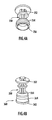
- FIGS. 8A and 8B illustrate front perspective views of the lower assembly of the posable/repositionable toy of FIG. 7 , showing the connection of an accessory article of clothing to the lower assembly.
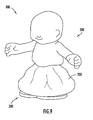
- FIG. 9 illustrates a front perspective view of the posable/repositionable toy of FIG. 7 , showing the assembled figure and the capturing of the accessory article of clothing between the upper and lower assemblies.
- FIG. 1 is an exploded view of a posable/repositionable toy in accordance with an embodiment of the present invention.
- the posable/repositionable toy may comprise a figure 100 including a first or lower assembly 200 and a second or upper assembly 300.
- the components of the lower assembly 200 and upper assembly 300 may be formed from materials including, but not limited to, plastics/thermoplastics such as acrylonitrile butadiene styrene (ABS) and/or polyvinyl chloride (PVC), as well as natural materials such as wood.
- ABS acrylonitrile butadiene styrene
- PVC polyvinyl chloride
- the lower assembly 200 and the upper assembly 300 are formed utilizing a combination of ABS and PVC components.
- the components may be formed utilizing, e.g., conventional molding processes such as blow molding, injection molding, insert molding, over-molding, etc.
- the lower assembly 200 may include a support or leg section 210 and a base or pelvic section 220.
- the base section 220 may include a bore or channel (extending, e.g., generally horizontally through the pelvic section 220), as well as a connection post 260 extending, e.g., generally vertically from the base section 220.
- the connection post 260 is configured to mate with the upper assembly 300.
- the upper (distal) end of the connection post 260 includes a flange or rim 262 and a recessed portion 264 extending about its periphery.
- the recessed portion 264 in combination with the rim 262, forms a shoulder or ledge 265 that serves as a stop, preventing the separation of the upper assembly 300 from the lower assembly 200.
- the post 260 may rotatably capture the body cylinder 360 of the upper assembly 300 when mounted onto to the connection post 260 (described in greater detail below).
- FIG. 2A is an exploded view of the lower assembly of the posable/repositionable toy of FIG 1 .
- the leg section 210 of the lower assembly 200 may include a first leg member 212 coupled to a second leg member 214 via a rod 216.
- the base section 220 may include a front waist portion 230 and a rear waist portion 240.
- the front 230 and rear 240 waist portions may each include a cut-out area 225 that form a bore or channel when the waist portions 230, 240 are connected.
- the cut-out areas 225 of the waist portions 230, 240 are aligned such that the rod 216 of the leg section 210 is positioned within the cut-out areas 225.
- FIG. 2B is an isolated view of the lower assembly of the posable/repositionable toy of FIG 1 .
- the waist portions 230, 240 may be permanently secured to each other (e.g., via solvent welding) by capturing the rod 216 of the leg section 210 in the newly-formed bore 250.
- the rod 216 of the leg section 210 may be configured to move within the bore formed by the connected portions 230, 240 with the base section 220 pivoting about the rod 216.
- the connection of the leg section 210 to the base section 220 is not limited to the embodiment illustrated herein.
- the base section 220 may be formed from a unitary structure (e.g., the base section 220 may be over-molded onto the leg section 210 (not illustrated)).
- the base section 220 including waist portions 230, 240
- the leg section 210 may be formed from PVC.
- the upper assembly 300 may include a figure upper body 310 including a torso 320, arms 330, and a head 340.
- the upper assembly 300 may further include a core member or spine 350 and a body cylinder or cap 360 (also called a plug).
- the body cylinder 360 may include a structure configured to rotatably connect to the connection post 260 of the lower assembly 200, securing the spine 350 of the upper assembly 300 to the lower assembly 200.
- FIG. 3A is an isolated perspective view of the body cylinder 360.
- the body cylinder 360 includes a base 362 with a wall or flange 364 extending upward about the periphery of the base 362.
- a channel or bore 366, concentrically disposed with respect to the flange 364, may be defined by a series of angularly spaced, resilient tabs 368.
- the dimensions of the channel 366 may be chosen such that the tabs 368 slidingly, yet securely engage the connection post 260 of the lower assembly 200.
- the channel 366 of the body cylinder 360 receives the post 260 of the lower assembly 200.
- the connection post 260 of the lower assembly 200 may be axially urged into the channel 366 of the cylinder body 360.
- the resilient tabs 368 beginning in their normal position, initially flex outward to permit passage of the connection post 260 and/or rim 262. However, once the tabs 368 become positioned below the rim 262 and within the recessed portion 264, the tabs 368 return to their normal (un-flexed) position.
- the spine 350 supports the figure body.
- the spine 350 may include a cylindrical shaft 352 terminating in a socket 354 operable to mate with the body cylinder 360.
- the socket includes a lip 356 extending about the perimeter of the socket opening.
- the spine 350 may be inserted axially onto the body cylinder 360 until the socket 354 of the spine 350 engages the flange 364 of the body cylinder 360.
- the lip 356 becomes positioned between the gap existing between the wall 364 and the tabs 368 of the body cylinder 360 (see FIG. 3A ).
- the lip 356 may further compress the resilient tabs toward the connection post, which, in turn, makes separation of the lower assembly 200 from the upper assembly 300 more difficult.
- the body cylinder 360 may be permanently secured to the spine 350 using techniques such as solvent welding.
- the combined (connected) spine/cylinder structure is illustrated in FIG. 4B .
- the figure body 310 is secured to the combined spine/cylinder structure (e.g., it may be formed over the spine 350 via molding). Since the body cylinder 360 rotatably engages the connection post 260, the spine 350, fixed to the figure body 310, may also rotate about the axis defined by the connection post 260. Although any suitable materials may be utilized, in the illustrated embodiment, the spine 350 (including the cylindrical shaft 352 and the socket 354) and the body cylinder 360 (including the base 362, the flange 364, and the tabs 368) may be formed from ABS, while the figure body 310 (including the torso 320, the arms 330, and the head 340) may be formed from PVC.
- the leg section 210 may be coupled to the base section 220 as described above.
- the spine 350 may be coupled to the body cylinder 360 as described above ( FIG. 4B ), and the figure body 310 may then be over-molded onto the combined spine/cylinder 350/360 structure, fixing the figure body 310 thereto ( FIG. 4C ).
- the upper assembly 300 may be coupled to the lower assembly 200.
- the body cylinder 360 of the upper assembly 300 mates with the post 260 of the lower assembly 200, with the tabs 368 engaging the post 260 as described above. This provides a substantially permanent connection between the upper assembly 300 and the lower assembly 200, while enabling the movement (for example, rotation) of the upper assembly with respect to the lower assembly (and vice versa).
- the present invention allows for the production of a posable/repositionable toy 100 without the use of conventional fasteners (screws, bolts, rivets, etc., all of which may be categorized as "small parts" for a product designed for children under three years of age), while providing a toy 100 that may be posed/repositioned along plural degrees of freedom.
- the leg section 210 is adapted to rotate about the base section 220 (e.g., about a horizontal axis) to create a bending motion of the toy 100 (indicated by arrow B).
- the figure body 310 (and the entire upper assembly 300) is adapted to rotate with respect to the entire lower assembly 200 (e.g., about a generally vertical axis) to create a twisting motion of the toy 100.
- FIGS. 7 —9 illustrate a posable toy 100 in accordance with another embodiment of the present invention.
- the posable toy 100 includes a general structure similar to that described above with reference to FIGS. 1 ⁇ 6, having a lower assembly 200 and an upper assembly 300 overmolded with a figure body 310.
- the posable toy 100 further includes an accessory 700 in the form of an article of clothing.
- the article of clothing may include any decorative or functional accessory including, but not limited to, dresses, pants, shorts, belts, skirts, weapons, bags, etc.
- the accessory may be formed from materials including, but not limited to, softgoods (e.g., cloth), plastic, wood, etc.
- the accessory 700 may include an aperture 710 with dimensions slightly larger than the dimensions (e.g., diameter) of the of the connection post 260.
- the connection post 260 is inserted through the aperture, positioning the accessory 700 onto the lower assembly 200 as illustrated in FIG. 8B .
- the upper assembly 300 may then be secured to the connection post 260 as described above, with the body cylinder 360 pressing the accessory 700 against the lower assembly 200. In this manner the accessory 700 is non-removably trapped between the upper assembly 300 and the lower assembly 200, securing it to the toy 100 ( FIG. 9 ).
- the posable/repositionable toy can be of any size and shape, and may be formed from any suitable materials.
- the present invention cover the modifications and variations of this invention that come within the scope of the appended claims. It is to be understood that terms such as “left”, “right” “top”, “bottom”, “front”, “rear”, “side”, “height”, “length”, “width”, “upper”, “lower”, “interior”, “exterior”, “inner”, “outer” and the like as may be used herein, merely describe points of reference and do not limit the present invention to any particular orientation or configuration.
Landscapes
- Toys (AREA)
Claims (13)
- Verbindungsanordnung für ein Spielzeug mit verstellbaren Abschnitten, wobei die Verbindungsanordnung umfasst:eine Bein-Anordnung (200), die enthält:einen Basisabschnitt (220), undeinen Verbindungszapfen (260), der sich von dem Basisabschnitt (220) aus erstreckt,wobei der Verbindungszapfen (260) ein Zapfen-Hinterende, ein Zapfen-Vorderendesowie einen Kranz (262) enthält, der am Zapfen-Vorderende angeordnet ist; und eine Körper-Anordnung (300), die mit der Bein-Anordnung (200) gekoppelt ist, dadurch gekennzeichnet, dass die Körper-Anordnung (300) enthält:einen Steckverbinder (360), der einen Sockel (362), eine Vielzahl elastischer Zungen (368), die sich von dem Sockel (362) aus erstrecken und einen Kanal (366) bilden, der in Funktion den Verbindungszapfen (260) aufnehmen kann, wobei die elastischen Zungen (368) in winklig beabstandeter Beziehung um den Sockel (362) herum ausgerichtet sind, undein Kernelement (350), das zum Koppeln mit dem Steckverbinder (360) eingerichtet ist,wobei der Steckverbinder (360) auf dem Verbindungszapfen (260) positioniert ist und das Kernelement (350) mit den elastischen Zungen (368) in Eingriff ist, wenn das Kernelement (350) mit dem Steckverbinder (360) gekoppelt ist.
- Verbindungsanordnung nach Anspruch 1, wobei der Steckverbinder (360) drehbar mit dem Verbindungszapfen (260) der Bein-Anordnung (200) gekoppelt ist.
- Verbindungsanordnung nach Anspruch 1 oder 2, wobei das Kernelement (350) des Weiteren umfasst:eine Welle (352) mit einem hinteren Ende und einem vorderen Ende, undeine Aufnahme (354), die an dem hinteren Ende der Welle (352) angeordnet ist, wobei die Aufnahme (354) in Funktion die Zungen (368) des Steckverbinders (360) aufnehmen kann.
- Verbindungsanordnung nach Anspruch 3, wobei:der Steckverbinder (360) des Weiteren einen Flansch (364) umfasst, der sich um einen Umfang des Sockels (362) herum erstreckt, der Flansch (364) von den Zungen (368) beabstandet ist, so dass ein Zwischenraum zwischen dem Flansch (364) und den Zungen (368) gebildet wird; unddie Aufnahme (354) eine Lippe (356) umfasst, die so in den Zwischenraum eingeführt ist, dass die Lippe (356) die Zungen (368) zusammendrückt, wenn die Aufnahme (354) mit dem Steckverbinder (360) gekoppelt ist.
- Verbindungsanordnung nach den Ansprüchen 3 oder 4, wobei das Kernelement (350) des Weiteren eine Spielzeugfigur (310) umfasst, die auf die Welle (352) aufgeformt ist.
- Verbindungsanordnung nach einem vorangehenden Ansprüche, wobei:der Verbindungszapfen (260) der Bein-Anordnung (200) des Weiteren einen zurückgesetzten Bereich (264) umfasst, durch den ein Absatz (265) hinter einem Kranz (262) des Verbindungszapfens (260) gebildet wird; unddie federnden Zungen (368) in dem zurückgesetzten Bereich (264) angeordnet sind, um die Trennung des Steckverbinders (360) von dem Verbindungszapfen (260) zu verhindern.
- Verbindungsanordnung nach einem der vorangehenden Ansprüche, wobei die Bein-Anordnung (200) des Weiteren einen Beinabschnitt (210) umfasst, der enthält:ein erstes Beinelement (212);ein zweites Beinelement (214); undeine Stange (216), die das erste Beinelement (212) mit dem zweiten Beinelement (214) verbindet.
- Verbindungsanordnung nach Anspruch 7, wobei der Beinabschnitt (210) drehbar mit dem Verbindungszapfen (260) gekoppelt ist.
- Verbindungsanordnung nach einem der vorangehenden Ansprüche, wobei das Kernelement (350) die federnden Zungen (368) zusammendrückt.
- Verbindungsanordnung nach einem der vorangehenden Ansprüche, wobei das Kernelement (350) die federnden Zungen (368) nach innen auf den Verbindungszapfen (260) zu drückt.
- Verbindungsanordnung nach einem der vorangehenden Ansprüche, wobei das Kernelement (350) eine Welle (352) mit einer Aufnahme (354) umfasst, die an einem Ende der Welle angeordnet ist, und die Aufnahme die federnden Zungen (368) auf den Verbindungszapfen (260) zu drückt.
- Verfahren zum Ausbilden einer Verbindungsanordnung für eine posierbare/verstellbare Spielzeugfigur, das umfasst:a) Ausbilden einer Bein-Anordnung (200), die einen Verbindungszapfen (260) umfasst;b) Ausbilden einer Körper-Anordnung (300), dadurch gekennzeichnet, dass die Körper-Anordnung (300) umfasst:einen Steckverbinder (360), der eine Vielzahl federnder Zungen (368) enthält, die einen Kanal (366) bilden, der den Verbindungszapfen (260) der Bein-Anordnung aufnimmt, undein Kernelement (350), das in Funktion die Vielzahl federnder Zungen (368) biegen kann; undc) Koppeln der Bein-Anordnung (200) mit der Körper-Anordnung (300) durch Einführen des Verbindungszapfens (260) in den Kanal (366) des Steckverbinders (360), wobei das Kernelement (350) die Vielzahl federnder Zungen (368) biegt,wobei der Steckverbinder (360) so eingerichtet ist, dass er sich um den Verbindungszapfen herum dreht,
und dadurch, dass das Kernelement (350) die Vielzahl federnder Zungen (368) auf den Zapfen (360) zu biegt, um die Bein-Anordnung (200) an der Körper-Anordnung (300) zu befestigen. - Verfahren nach Anspruch 12, wobei der Verbindungszapfen (260) des Weiteren einen zurückgesetzten Bereich (264) umfasst, und Schritt c) des Weiteren Positionieren der Vielzahl federnder Zungen (368) in dem zurückgesetzten Bereich des Verbindungszapfens (260) umfasst.
Applications Claiming Priority (3)
| Application Number | Priority Date | Filing Date | Title |
|---|---|---|---|
| US82430506P | 2006-09-01 | 2006-09-01 | |
| US11/847,729 US7736214B2 (en) | 2006-09-01 | 2007-08-30 | Posable toy and method of forming |
| PCT/US2007/077335 WO2008028100A2 (en) | 2006-09-01 | 2007-08-31 | Posable toy and method of forming |
Publications (3)
| Publication Number | Publication Date |
|---|---|
| EP2056945A2 EP2056945A2 (de) | 2009-05-13 |
| EP2056945A4 EP2056945A4 (de) | 2010-08-04 |
| EP2056945B1 true EP2056945B1 (de) | 2013-03-13 |
Family
ID=39136930
Family Applications (1)
| Application Number | Title | Priority Date | Filing Date |
|---|---|---|---|
| EP07814599A Not-in-force EP2056945B1 (de) | 2006-09-01 | 2007-08-31 | Positionierbares spielzeug und herstellungsverfahren |
Country Status (6)
| Country | Link |
|---|---|
| US (2) | US7736214B2 (de) |
| EP (1) | EP2056945B1 (de) |
| CN (1) | CN101511439B (de) |
| AU (1) | AU2007289090B2 (de) |
| CA (1) | CA2662010A1 (de) |
| WO (1) | WO2008028100A2 (de) |
Families Citing this family (19)
| Publication number | Priority date | Publication date | Assignee | Title |
|---|---|---|---|---|
| US8403721B2 (en) * | 2010-04-23 | 2013-03-26 | Mattel, Inc. | Toy set and relay segments |
| US20120270471A1 (en) * | 2011-04-21 | 2012-10-25 | Mauricio Bedolla | Action toy and playset |
| GB2492209B (en) * | 2011-06-21 | 2014-02-12 | Mattel Inc | Toy figure with articulating limb |
| DE102012107872A1 (de) * | 2011-08-29 | 2013-02-28 | Mattel, Inc. | Spielzeugfigur mit Licht- und Klangeffekten |
| DE102012201132A1 (de) * | 2012-01-26 | 2013-08-01 | Bruder Spielwaren Gmbh + Co. Kg | Kupplung |
| FR2991221B1 (fr) * | 2012-06-01 | 2015-02-27 | Aldebaran Robotics | Colonne vertebrale pour robot humanoide |
| US9205344B2 (en) | 2013-02-08 | 2015-12-08 | Hasbro, Inc. | Toy figure assembly |
| USD688334S1 (en) | 2013-03-13 | 2013-08-20 | Mega Brands Inc. | Toy figurine leg |
| USD688333S1 (en) | 2013-03-13 | 2013-08-20 | Mega Brands Inc. | Toy figurine |
| USD688335S1 (en) | 2013-03-13 | 2013-08-20 | Mega Brands Inc. | Toy figurine head |
| US20160101558A1 (en) * | 2014-10-10 | 2016-04-14 | Leo D. Bernstein & Sons, Inc. | Method For Molding Hollow Objects From Recycled Polymer |
| KR101764357B1 (ko) * | 2015-09-04 | 2017-08-03 | (주)짐월드 | 장난감 블록 |
| US9573075B1 (en) * | 2016-05-17 | 2017-02-21 | Kids Toy Clab, LLC. | Illuminated toy construction apparatus |
| USD842938S1 (en) | 2017-07-20 | 2019-03-12 | Mattel-Mega Holdings (Us), Llc | Figurine |
| USD837311S1 (en) | 2017-07-20 | 2019-01-01 | Mattel-Mega Holdings (Us), Llc | Figurine |
| USD842396S1 (en) | 2017-07-20 | 2019-03-05 | Mattel-Mega Holdings (Us), Llc | Figurine |
| CN107648861A (zh) * | 2017-09-27 | 2018-02-02 | 广东启睿动漫有限公司 | 一种拼装玩具 |
| DK3917633T3 (da) * | 2019-01-29 | 2023-09-04 | Lego As | Legetøjssystem og legetøjsfigurhoved og hovedbeklædning |
| USD1117532S1 (en) * | 2025-01-24 | 2026-03-10 | Guangdong Pinqi Culture and Technology Co., Ltd. | Toy building block |
Family Cites Families (20)
| Publication number | Priority date | Publication date | Assignee | Title |
|---|---|---|---|---|
| US2152311A (en) | 1935-06-11 | 1939-03-28 | Jacobson Emanuel | Seamless rubber figure |
| US2649806A (en) * | 1949-07-19 | 1953-08-25 | Frank P Monaghan | Doll or manikin joint |
| US3740894A (en) | 1971-05-28 | 1973-06-26 | Hasbro Industries Inc | Doll construction |
| US3874113A (en) | 1973-02-02 | 1975-04-01 | Georg Brandstatter | Doll wherein head connects to a support member, thereby locking on body and limbs |
| US3990175A (en) | 1974-08-26 | 1976-11-09 | Marvin Glass & Associates | Doll head for excreting liquid therethrough, and method of making same |
| US3946517A (en) | 1975-02-13 | 1976-03-30 | Adolph E. Goldfarb | Animal characterization figures with articulatable body components |
| DE2700969C3 (de) * | 1977-01-12 | 1981-10-22 | BIG-Spielwarenfabrik Dipl.-Ing. Ernst A. Bettag, 8510 Fürth | Beinpaarlagerung in einer zusammensetzbaren Spielfigur |
| IT1151841B (it) | 1981-07-22 | 1986-12-24 | Ken Yamamoto | Stampo per la formatura di articoli concatenati ed articoli ottenuti mediante tale stampo |
| US4526553A (en) * | 1983-04-11 | 1985-07-02 | Mattel, Inc. | Floppy limbed water immersible figure toy |
| US4571209A (en) | 1983-05-06 | 1986-02-18 | Manning Peter R | Articulated toy figure |
| ES285702Y (es) * | 1985-03-28 | 1986-05-16 | Globetoy's,S.A. | Muneco de tipo desarmable,perfeccionado |
| GB2191956A (en) | 1986-06-27 | 1987-12-31 | Warick Miniatures Limited | Joints for models, e.g. toy figures |
| DE3727861C1 (de) | 1987-08-20 | 1988-06-16 | Simro Ag | Gelenk zum Verbinden eines Buegelschaftes mit einem Gelenkstueck einer Brille sowie Verfahren zur Herstellung eines solchen Gelenks |
| DE4202351C2 (de) | 1992-01-29 | 1995-01-19 | Fickenscher & Co Gmbh Werkzeug | Verfahren zum Spritzgießen von Gegenständen aus wenigstens zwei Teilen |
| JPH07137179A (ja) | 1993-07-19 | 1995-05-30 | Xerox Corp | 2つの部材を移動可能に連結した組立体を製造する方法 |
| JP3163255B2 (ja) | 1996-05-31 | 2001-05-08 | 株式会社バンダイ | 連結装置及びその連結装置の製造方法並びに可動体及びその可動体の製造方法 |
| US6089950A (en) * | 1998-06-01 | 2000-07-18 | C. J. Associates, Ltd. | Toy figure with articulating joints |
| US6607684B1 (en) | 2000-09-19 | 2003-08-19 | C. J. Associates, Ltd. | Method of making a jointed linkage support system |
| KR100624063B1 (ko) | 2002-05-31 | 2006-09-19 | 매텔 인코포레이티드 | 플렉서블한 인형 및 포즈 가능형 작동 인물상 |
| JP2005344936A (ja) * | 2005-08-04 | 2005-12-15 | Mega House:Kk | 関節装置及び人形体 |
-
2007
- 2007-08-30 US US11/847,729 patent/US7736214B2/en not_active Expired - Fee Related
- 2007-08-31 EP EP07814599A patent/EP2056945B1/de not_active Not-in-force
- 2007-08-31 CN CN200780031941XA patent/CN101511439B/zh not_active Expired - Fee Related
- 2007-08-31 CA CA002662010A patent/CA2662010A1/en not_active Abandoned
- 2007-08-31 WO PCT/US2007/077335 patent/WO2008028100A2/en not_active Ceased
- 2007-08-31 AU AU2007289090A patent/AU2007289090B2/en not_active Ceased
-
2010
- 2010-04-29 US US12/769,729 patent/US8210891B2/en not_active Expired - Fee Related
Also Published As
| Publication number | Publication date |
|---|---|
| US8210891B2 (en) | 2012-07-03 |
| CN101511439A (zh) | 2009-08-19 |
| WO2008028100A2 (en) | 2008-03-06 |
| AU2007289090B2 (en) | 2012-09-06 |
| EP2056945A4 (de) | 2010-08-04 |
| US20080057827A1 (en) | 2008-03-06 |
| EP2056945A2 (de) | 2009-05-13 |
| AU2007289090A1 (en) | 2008-03-06 |
| US20100210170A1 (en) | 2010-08-19 |
| CA2662010A1 (en) | 2008-03-06 |
| CN101511439B (zh) | 2011-02-09 |
| WO2008028100A3 (en) | 2008-10-30 |
| US7736214B2 (en) | 2010-06-15 |
Similar Documents
| Publication | Publication Date | Title |
|---|---|---|
| EP2056945B1 (de) | Positionierbares spielzeug und herstellungsverfahren | |
| US4268991A (en) | Soft flexible articulated doll | |
| US20190282913A1 (en) | Figurine with magnetic assembly component | |
| EP0682896A1 (de) | Durch bogenförmige Elemente unterstützter Stuhl | |
| US6264077B1 (en) | Hanger for display of belts | |
| US20060172657A1 (en) | Structure of hula-hoop | |
| CN110038309A (zh) | 可操纵的多件式玩具 | |
| WO2005028058A2 (en) | Linkable-shared friendship objects | |
| US7000254B1 (en) | Costume construction | |
| US20020129464A1 (en) | Door hinge safety cover | |
| CN209123330U (zh) | 一种新型积木人仔 | |
| US5647786A (en) | Stuffed personal computer toy | |
| CN110102065A (zh) | 一种变形玩具 | |
| CN213621273U (zh) | 双色分体插接组合式奶粉盖的防盗装置 | |
| US834077A (en) | Toy. | |
| CN218485149U (zh) | 一种虚拟人物模型 | |
| KR200464023Y1 (ko) | 완구조립을 위한 골격용 기본모듈 및 그 기본모듈을 이용하여 조립된 완구 | |
| JP2003505219A (ja) | 改良された人形組立体 | |
| CN201501594U (zh) | 酒瓶防伪扣圈的安装结构 | |
| US12420210B2 (en) | Bobblehead key chain | |
| JP3158902U (ja) | 起き上がり小法師 | |
| CN215423144U (zh) | 一种具有一体式拉片的拉头、拉链及物品 | |
| CN100534564C (zh) | 教育性的揿扣在一起的玩具车辆系统 | |
| CN208660355U (zh) | 玩具套装和合体配件 | |
| CN209378431U (zh) | 一种组合式游乐设备 |
Legal Events
| Date | Code | Title | Description |
|---|---|---|---|
| PUAI | Public reference made under article 153(3) epc to a published international application that has entered the european phase |
Free format text: ORIGINAL CODE: 0009012 |
|
| 17P | Request for examination filed |
Effective date: 20090217 |
|
| AK | Designated contracting states |
Kind code of ref document: A2 Designated state(s): AT BE BG CH CY CZ DE DK EE ES FI FR GB GR HU IE IS IT LI LT LU LV MC MT NL PL PT RO SE SI SK TR |
|
| AX | Request for extension of the european patent |
Extension state: AL BA HR MK RS |
|
| DAX | Request for extension of the european patent (deleted) | ||
| A4 | Supplementary search report drawn up and despatched |
Effective date: 20100701 |
|
| RBV | Designated contracting states (corrected) |
Designated state(s): DE FR GB |
|
| GRAP | Despatch of communication of intention to grant a patent |
Free format text: ORIGINAL CODE: EPIDOSNIGR1 |
|
| GRAS | Grant fee paid |
Free format text: ORIGINAL CODE: EPIDOSNIGR3 |
|
| GRAA | (expected) grant |
Free format text: ORIGINAL CODE: 0009210 |
|
| AK | Designated contracting states |
Kind code of ref document: B1 Designated state(s): DE FR GB |
|
| REG | Reference to a national code |
Ref country code: GB Ref legal event code: FG4D |
|
| REG | Reference to a national code |
Ref country code: DE Ref legal event code: R096 Ref document number: 602007029091 Country of ref document: DE Effective date: 20130508 |
|
| PLBE | No opposition filed within time limit |
Free format text: ORIGINAL CODE: 0009261 |
|
| STAA | Information on the status of an ep patent application or granted ep patent |
Free format text: STATUS: NO OPPOSITION FILED WITHIN TIME LIMIT |
|
| 26N | No opposition filed |
Effective date: 20131216 |
|
| REG | Reference to a national code |
Ref country code: DE Ref legal event code: R097 Ref document number: 602007029091 Country of ref document: DE Effective date: 20131216 |
|
| PGFP | Annual fee paid to national office [announced via postgrant information from national office to epo] |
Ref country code: DE Payment date: 20140827 Year of fee payment: 8 |
|
| PGFP | Annual fee paid to national office [announced via postgrant information from national office to epo] |
Ref country code: FR Payment date: 20140818 Year of fee payment: 8 Ref country code: GB Payment date: 20140827 Year of fee payment: 8 |
|
| REG | Reference to a national code |
Ref country code: DE Ref legal event code: R119 Ref document number: 602007029091 Country of ref document: DE |
|
| GBPC | Gb: european patent ceased through non-payment of renewal fee |
Effective date: 20150831 |
|
| REG | Reference to a national code |
Ref country code: FR Ref legal event code: ST Effective date: 20160429 |
|
| PG25 | Lapsed in a contracting state [announced via postgrant information from national office to epo] |
Ref country code: GB Free format text: LAPSE BECAUSE OF NON-PAYMENT OF DUE FEES Effective date: 20150831 Ref country code: DE Free format text: LAPSE BECAUSE OF NON-PAYMENT OF DUE FEES Effective date: 20160301 |
|
| PG25 | Lapsed in a contracting state [announced via postgrant information from national office to epo] |
Ref country code: FR Free format text: LAPSE BECAUSE OF NON-PAYMENT OF DUE FEES Effective date: 20150831 |