EP2056712B1 - Verfahren zum nachweis von karies - Google Patents
Verfahren zum nachweis von karies Download PDFInfo
- Publication number
- EP2056712B1 EP2056712B1 EP07837356.0A EP07837356A EP2056712B1 EP 2056712 B1 EP2056712 B1 EP 2056712B1 EP 07837356 A EP07837356 A EP 07837356A EP 2056712 B1 EP2056712 B1 EP 2056712B1
- Authority
- EP
- European Patent Office
- Prior art keywords
- image data
- reflectance
- image
- fluorescence
- tooth
- Prior art date
- Legal status (The legal status is an assumption and is not a legal conclusion. Google has not performed a legal analysis and makes no representation as to the accuracy of the status listed.)
- Not-in-force
Links
- 238000000034 method Methods 0.000 title claims description 74
- 208000002925 dental caries Diseases 0.000 title description 67
- 238000001514 detection method Methods 0.000 title description 30
- 238000002073 fluorescence micrograph Methods 0.000 claims description 37
- 238000009826 distribution Methods 0.000 claims description 6
- 238000003384 imaging method Methods 0.000 description 53
- 230000003595 spectral effect Effects 0.000 description 29
- 238000012545 processing Methods 0.000 description 21
- 238000005286 illumination Methods 0.000 description 19
- 230000005284 excitation Effects 0.000 description 14
- 230000000694 effects Effects 0.000 description 13
- 230000006872 improvement Effects 0.000 description 12
- 230000010287 polarization Effects 0.000 description 12
- 230000004044 response Effects 0.000 description 12
- 230000008901 benefit Effects 0.000 description 11
- 238000013459 approach Methods 0.000 description 9
- 238000000799 fluorescence microscopy Methods 0.000 description 9
- 238000010586 diagram Methods 0.000 description 8
- 238000013507 mapping Methods 0.000 description 7
- 208000015181 infectious disease Diseases 0.000 description 6
- 238000005259 measurement Methods 0.000 description 6
- 238000001228 spectrum Methods 0.000 description 6
- 230000008859 change Effects 0.000 description 5
- 238000001506 fluorescence spectroscopy Methods 0.000 description 5
- 230000003902 lesion Effects 0.000 description 5
- 210000003298 dental enamel Anatomy 0.000 description 4
- 238000004020 luminiscence type Methods 0.000 description 4
- 230000003287 optical effect Effects 0.000 description 4
- 230000000007 visual effect Effects 0.000 description 4
- 230000001580 bacterial effect Effects 0.000 description 3
- 239000006227 byproduct Substances 0.000 description 3
- 230000003750 conditioning effect Effects 0.000 description 3
- 238000007796 conventional method Methods 0.000 description 3
- 230000001419 dependent effect Effects 0.000 description 3
- 238000002795 fluorescence method Methods 0.000 description 3
- 230000001965 increasing effect Effects 0.000 description 3
- 238000012986 modification Methods 0.000 description 3
- 230000004048 modification Effects 0.000 description 3
- 230000003449 preventive effect Effects 0.000 description 3
- 230000008569 process Effects 0.000 description 3
- 208000008312 Tooth Loss Diseases 0.000 description 2
- 238000000149 argon plasma sintering Methods 0.000 description 2
- 230000005540 biological transmission Effects 0.000 description 2
- 238000003745 diagnosis Methods 0.000 description 2
- 238000001917 fluorescence detection Methods 0.000 description 2
- 239000013307 optical fiber Substances 0.000 description 2
- 239000000523 sample Substances 0.000 description 2
- 241000894006 Bacteria Species 0.000 description 1
- 238000003491 array Methods 0.000 description 1
- 230000002238 attenuated effect Effects 0.000 description 1
- 230000009286 beneficial effect Effects 0.000 description 1
- 238000004040 coloring Methods 0.000 description 1
- 230000002301 combined effect Effects 0.000 description 1
- 239000002131 composite material Substances 0.000 description 1
- 230000003247 decreasing effect Effects 0.000 description 1
- 210000004268 dentin Anatomy 0.000 description 1
- 230000001627 detrimental effect Effects 0.000 description 1
- 238000011161 development Methods 0.000 description 1
- 201000010099 disease Diseases 0.000 description 1
- 208000037265 diseases, disorders, signs and symptoms Diseases 0.000 description 1
- 230000002708 enhancing effect Effects 0.000 description 1
- 239000000835 fiber Substances 0.000 description 1
- 238000001914 filtration Methods 0.000 description 1
- 238000010191 image analysis Methods 0.000 description 1
- 229910052500 inorganic mineral Inorganic materials 0.000 description 1
- 239000007788 liquid Substances 0.000 description 1
- 238000004519 manufacturing process Methods 0.000 description 1
- 239000011707 mineral Substances 0.000 description 1
- 239000000203 mixture Substances 0.000 description 1
- 238000012544 monitoring process Methods 0.000 description 1
- 238000012014 optical coherence tomography Methods 0.000 description 1
- 238000005457 optimization Methods 0.000 description 1
- 230000002265 prevention Effects 0.000 description 1
- 238000003672 processing method Methods 0.000 description 1
- 239000000047 product Substances 0.000 description 1
- 230000005855 radiation Effects 0.000 description 1
- 230000002829 reductive effect Effects 0.000 description 1
- 238000011160 research Methods 0.000 description 1
- 230000002441 reversible effect Effects 0.000 description 1
- 230000035945 sensitivity Effects 0.000 description 1
- 238000000926 separation method Methods 0.000 description 1
- 230000007480 spreading Effects 0.000 description 1
- 238000003892 spreading Methods 0.000 description 1
- 238000003860 storage Methods 0.000 description 1
- 230000009466 transformation Effects 0.000 description 1
- 230000001131 transforming effect Effects 0.000 description 1
- 238000001429 visible spectrum Methods 0.000 description 1
- 229910052724 xenon Inorganic materials 0.000 description 1
- FHNFHKCVQCLJFQ-UHFFFAOYSA-N xenon atom Chemical compound [Xe] FHNFHKCVQCLJFQ-UHFFFAOYSA-N 0.000 description 1
Images


Classifications
-
- A—HUMAN NECESSITIES
- A61—MEDICAL OR VETERINARY SCIENCE; HYGIENE
- A61B—DIAGNOSIS; SURGERY; IDENTIFICATION
- A61B5/00—Measuring for diagnostic purposes; Identification of persons
- A61B5/0059—Measuring for diagnostic purposes; Identification of persons using light, e.g. diagnosis by transillumination, diascopy, fluorescence
- A61B5/0082—Measuring for diagnostic purposes; Identification of persons using light, e.g. diagnosis by transillumination, diascopy, fluorescence adapted for particular medical purposes
- A61B5/0088—Measuring for diagnostic purposes; Identification of persons using light, e.g. diagnosis by transillumination, diascopy, fluorescence adapted for particular medical purposes for oral or dental tissue
Definitions
- This invention generally relates to a method and apparatus for dental imaging and more particularly to an improved method for early detection of caries using fluorescence and scattering of light.
- QLF quantitative light-induced fluorescence
- U.S. Patent Application Publication No. 2004/0202356 (Stookey et al. ) describes mathematical processing of spectral changes in fluorescence in order to detect caries in different stages with improved accuracy. Acknowledging the difficulty of early detection when using spectral fluorescence measurements, the '2356 Stookey et al. disclosure describes approaches for enhancing the spectral values obtained, effecting a transformation of the spectral data that is adapted to the spectral response of the camera that obtains the fluorescent image.
- FR 2 856 546 A describes a method of acquiring and processing images of a tooth.
- the method consists of; illuminating the tooth with ultraviolet light; using video means to take images of the illuminated portion of the tooth; measuring at each point of said images the spectral intensity of the luminescence emitted by the tooth in two wavelength bands respectively at high energy and at low energy; taking the ratio of said measurements at each point of the image of the article; and comparing said ratios with a predetermined value.
- the method further consists of: taking at least one color video image of said portion of the article illuminated in ambient light; taking at least one color video image of the luminescence produced by said portion of the article in response to being illuminated in ultraviolet light; subtracting the ambient light video image from the luminescence video image at each point of the luminescence image in order to obtain a pure image; extracting the spectral components of the pure image in said high-energy and low-energy wavelength bands; and taking the ratios of said components at each point of the image and in comparing said ratios with a predetermined value.
- fluorescence can be used to detect dental caries using either of two characteristic responses: First, excitation by a blue light source causes healthy tooth tissue to fluoresce in the green spectrum. Secondly, excitation by a red light source can cause bacterial by-products, such as those indicating caries, to fluoresce in the red spectrum.
- reflectance In order for an understanding of how light is used in the present invention, it is important to give more precise definition to the terms “reflectance” and “back-scattering” as they are used in biomedical applications in general and, more particularly, in the method and apparatus of the present invention.
- reflectance generally denotes the sum total of both specular reflectance and scattered reflectance. (Specular reflection is that component of the excitation light that is reflected by the tooth surface at the same angle as the incident angle.)
- specular component of reflectance is of no interest and is, instead, generally detrimental to obtaining an image or measurement from a sample.
- the component of reflectance that is of interest for the present application is from back-scattered light only. Specular reflectance must be blocked or otherwise removed from the imaging path.
- the term "back-scattered reflectance” is used in the present application to denote the component of reflectance that is of interest.
- “Back-scattered reflectance” is defined as that component of the excitation light that is elastically back-scattered over a wide range of angles by the illuminated tooth structure.
- Reflectance image data refers to image data obtained from back-scattered reflectance only, since specular reflectance is blocked or kept to a minimum.
- back-scattered reflectance may also be referred to as back-reflectance or simply as back-scattering. Back-scattered reflectance is at the same wavelength as the excitation light.
- the present invention takes advantage of the observed back-scattering behavior for incipient caries and uses this effect, in combination with fluorescence effects described previously in the background section, to provide an improved capability for dental imaging to detect caries.
- the inventive technique hereafter referred to as fluorescence imaging with reflectance enhancement (FIRE)
- FIRE fluorescence imaging with reflectance enhancement
- FIRE detection can be accurate at an earlier stage of caries infection than has been exhibited using existing fluorescence approaches that measure fluorescence alone.
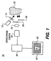
- a light source 12 directs an incident light, at a blue wavelength range or other suitable wavelength range, toward tooth 20 through an optional lens 14 or other light beam conditioning component.
- the tooth 20 may be illuminated at a proximal surface (as shown) or at an occlusal surface (not shown).
- Two components of light are then detected by a monochrome camera 30 through a lens 22: a back-scattered light component having the same wavelength as the incident light and having measurable reflectance; and a fluorescent light that has been excited due to the incident light.
- specular reflection causes false positives and is undesirable.
- the camera 30 is positioned at a suitable angle with respect to the light source 12. This allows imaging of back-scattered light without the confounding influence of a specularly reflected component.
- monochrome camera 30 has color filters 26 and 28.
- One of color filters 26 and 28 is used during reflectance imaging, the other is used during fluorescence imaging.
- a processing apparatus 38 obtains and processes the reflectance and fluorescence image data and forms a FIRE image 60.
- FIRE image 60 is an enhanced diagnostic image that can be printed or can appear on a display 40.
- FIRE image 60 data can also be transmitted to storage or transmitted to another site for display.
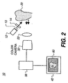
- FIG. 2 there is shown an alternate embodiment using a color camera 32.
- auxiliary filters would not generally be needed, since color camera 32 would be able to obtain the reflectance and fluorescence images from the color separations (also called color planes) of the full color image of tooth 20.
- Light source 12 is typically centered around a blue wavelength, such as about 405 nm in one embodiment. In practice, light source 12 could emit light ranging in wavelength from an upper ultraviolet range to a deeper blue, between about 300 and 500nm.
- Light source 12 can be a laser or could be fabricated using one or more light emitting diodes (LEDs). Alternately, a broadband source, such as a xenon lamp, having a supporting color filter for passing the desired wavelengths could be used.
- Lens 14 or other optical element may serve to condition the incident light, such as by controlling the uniformity and size of the illumination area. For example, a diffuser 13, shown as a dotted line in Figure 2 , might be used before or after lens 14 to smooth out the hot spots of an LED beam.
- the path of illumination light might include light guiding or light distributing structures such as optical fibers or a liquid light guide, for example (not shown).
- Light level is typically a few milliwatts in intensity, but can be more or less, depending on the light conditioning and sensing components used.
- the illumination arrangement could alternately direct light at normal incidence, turned through a beamsplitter 34. Camera 32 would then be disposed to obtain the image light that is transmitted through beamsplitter 34.
- Other options for illumination include multiple light sources directed at the tooth with angular incidence from one or more sides. Alternately, the illumination might use an annular ring or an arrangement of LED sources distributed about a center such as in a circular array to provide light uniformly from multiple angles. Illumination could also be provided through an optical fiber or fiber array.
- the imaging optics could include any suitable arrangement of optical components, with possible configurations ranging from a single lens component to a multi-element lens. Clear imaging of the tooth surface, which is not flat but can have areas that are both smoothly contoured and highly ridged, requires that imaging optics have sufficient depth of focus. Preferably, for optimal resolution, the imaging optics provide an image size that substantially fills the sensor element of the camera. Telecentric optics are advantaged for lens 22, providing image-bearing light that is not highly dependent on ray angle.
- Image capture can be performed by either monochrome camera 30 ( Figure 1 ) or color camera 32 ( Figure 2 ).
- camera 30 or 32 employs a CMOS or CCD image sensor.
- the monochrome version would typically employ a retractable spectral filter 26, 28 suitable for the wavelength of interest.
- spectral filter 26 for capturing reflectance image data would transmit predominately blue light.
- Spectral filter 28 for capturing fluorescence image data would transmit light at a different wavelength, such as predominately green light.
- spectral filters 26 and 28 are automatically switched into place to allow capture of both reflectance and fluorescence images in very close succession. Both images are obtained from the same position to allow accurate registration of the image data.
- Spectral filter 28 would be optimized with a pass-band that captures fluorescence data over a range of suitable wavelengths.
- the fluorescent effect that has been obtained from tooth 20 can have a relative broad spectral distribution in the visible range, with light emitted that is outside the wavelength range of the light used for excitation.
- the fluorescent emission is typically between about 450 nm and 650 nm, while generally peaking in the green region, roughly from around 500 nm to about 600 nm.
- a green light filter is generally preferred for spectral filter 28 in order to obtain this fluorescence image at its highest energy levels.
- other ranges of the visible spectrum could also be used in other embodiments.
- spectral filter 26 would be optimized with a pass-band that captures reflectance data over a wavelength range covering at least a significant portion of the spectral energy of the light source 12 used.
- a blue light filter is generally used for spectral filter 26 in order to obtain the reflectance image at its highest energy level.
- Camera controls are suitably adjusted for obtaining each type of image. For example, when capturing the fluorescence image, it is necessary to make appropriate exposure adjustments for gain, shutter speed, and aperture, since this image may not be intense.
- color camera 32 Figure 2
- color filtering is performed by the color filter arrays on the camera image sensor. The reflectance image is captured in the blue color plane; simultaneously, the fluorescence image is captured in the green color plane. That is, a single exposure captures both back-scattered reflectance and fluorescence images.
- Processing apparatus 38 is typically a computer workstation but may, in its broadest application, be any type of control logic processing component or system that is capable of obtaining image data from camera 30 or 32 and executing image processing algorithms upon that data to generate the FIRE image 60 data. Processing apparatus 38 may be local or may connect to image sensing components over a networked interface.
- FIG. 5 there is shown, in schematic form, how the FIRE image 60 is formed according to the present invention.
- Two images of tooth 20 are obtained, a green fluorescence image 50 and a blue reflectance image 52.
- the reflectance light used for reflectance image 52 and its data is from back-scattered reflectance, with specular reflectance blocked or kept as low as possible.
- the carious region 58 may be imperceptible or barely perceptible in either fluorescence image 50 or reflectance image 52, taken individually.
- Processing apparatus 38 operates upon the image data using an image processing algorithm as discussed below for both images 50 and 52 and provides FIRE image 60 as a result.
- the contrast between carious region 58 and sound tooth structure is heightened, so that a caries condition is made more visible in FIRE image 60.
- Figure 6 shows the contrast improvement of the present invention in a side-by-side comparison with a visual white-light image 54 and conventional fluorescence methods.
- the carious region 58 may look indistinct from the surrounding healthy tooth structure in white-light image 54, either as perceived directly by eye or as captured by an intraoral camera.
- the carious region 58 may show up as a very faint, hardly noticeable shadow.
- the FIRE image 60 generated by the present invention, the same carious region 58 shows up as a darker, more detectable spot.
- the FIRE image 60 offers greater diagnostic value.
- processing of the image data uses both the reflectance and fluorescence image data to generate a final image that can be used to identify carious areas of the tooth.
- Copending U.S. Patent Application Serial No. 11/262,869 cited earlier, describes a scalar multiplication method for combining the fluorescence and reflectance data.
- image processing performs the following operation for each pixel: m * F value ⁇ n * R value where m and n are suitable multipliers (positive coefficients) and F value and R value are the code values obtained from fluorescence and reflectance image data, respectively.
- Back-scattered reflectance is higher (brighter) for image pixels in the carious region, yielding a higher reflectance value R value for these pixels than for surrounding pixels.
- the fluorescence meanwhile, is lower (darker) for image pixels in the carious region, yielding a lower fluorescence value F value for these pixels than for surrounding pixels.
- the fluorescence is considerably weaker in intensity compared to the reflectance.
- scalar multiplier n for reflectance value R value is one.
- a thresholding operation executed using image processing techniques familiar to those skilled in the imaging arts, or some other suitable conditioning of the combined image data used for FIRE image 60, may be used to further enhance the contrast between a carious region and sound tooth structure.
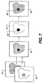
- FIG. 7 there is shown, in block diagram form, a sequence of image processing for generating an enhanced threshold FIRE image 64 according to one embodiment. Fluorescence image 50 and reflectance image 52 are first combined to form FIRE image 60, as described previously. A thresholding operation is next performed, providing threshold image 62 that defines more clearly the area of interest, carious region 58.
- threshold image 62 is combined with original FIRE image 60 to generate enhanced threshold FIRE image 64.
- results of threshold detection can also be superimposed onto a white light image 54 ( Figure 6 ) in order to definitively outline the location of a carious infection.
- m and n are dependent on the spectral content of the light source and the spectral response of the image capture system. There is variability in the center wavelength and spectral bandwidth from one LED to the next, for example. Similarly, variability exits in the spectral responses of the color filters and image sensors of different image capture systems. Such variations affect the relative magnitudes of the measured reflectance and fluorescence values. Therefore, it may be necessary to determine a different m and n value for each imaging apparatus 10 as a part of an initial calibration process. A calibration procedure used during the manufacturing of imaging apparatus 10 can then optimize the m and n values to provide the best possible contrast enhancement in the FIRE image that is formed.
- a spectral measurement of the light source 12 used for reflectance imaging is obtained. Then, spectral measurement is made of the fluorescent emission that is excited from the tooth. This data provides a profile of the relative amount of light energy available over each wavelength range of interest. Then the spectral response of camera 30 (with appropriate filters) or 32 is quantified against a known reference. These data are then used, for example, to generate a set of optimized multiplier m and n values to be used by processing apparatus 38 of the particular imaging apparatus 10 for forming FIRE image 60.
- scalar multiplication method provides improved results over conventional fluorescence imaging, however, there remains some room for improvement, particularly with respect to edge definition and overall image quality.
- One inherent problem with the scalar multiplication method is that multiplication of the weaker fluorescence signal also scales up the noise floor. This results in more noise and some loss of edge definition in the FIRE image.
- a different method hereafter called the asymmetric illuminance method.
- fluorescence and reflectance are obtained as separate captures, with more light delivered to the tooth for fluorescence imaging than for reflectance imaging.
- a significant increase in excitation light for fluorescence imaging results in a higher light level in the resulting fluorescence, with a significantly improved S/N ratio for the fluorescence image data.
- the fluorescent response can be brought to a level comparable to or slightly larger than the reflectance, allowing. straightforward subtraction to be used for obtaining the difference between the fluorescence and reflectance images used for FIRE imaging. It is emphasized that this method does not involve up-scaling of the fluorescence signal; thus there is no magnification of the noise floor.
- Increased illuminance can be obtained by increasing the drive current to the LED or other light source that is used for exciting fluorescent emission.
- the same light source 12 is used for both fluorescent and reflectance imaging.
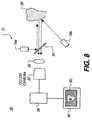
- a separate light source 16a serves for exciting fluorescence ( Figure 8 ).
- each imaging operation may require a separate illuminance level, making it necessary to capture separate fluorescence and reflectance images at different times. In one embodiment, these images are taken at a fraction of a second apart. Separate filters may be needed, possibly by switching rapidly into place according to the image that is being captured.
- Results from asymmetric illuminance imaging show improvement over the scalar multiplication method of Equation (1).
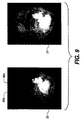
- Figure 9 shows two example FIRE images generated from the same tooth. At the left is an image 70 obtained using the scalar multiplication method. Image structure is noticeably darker, especially in the edge features. Also, carious lesions 86a and 86b are overly darkened, failing to show the distinctive stages of caries development between the two lesions. Image 72 on the right, taken using asymmetric illuminance imaging described with respect to this second embodiment, shows marked improvement in dynamic range and contrast and improved edge definition.
- Another alternative embodiment for combining fluorescence and reflectance images takes a different approach from the scalar multiplication or asymmetric illuminance imaging approaches just described.
- This "downshifting" or “offset” approach does not risk distortion of the image data, such as can result from scaling, nor does it require driving current to high levels.
- the downshifting imaging method can be characterized as keeping image values that are in a certain brightness range and maintaining the input/output ratio of those image values in the processing of the image. In effect, this method maintains the input/output relationship and structural integrity of the original data.
- the downshifting imaging method operates as follows:
- the downshifting imaging method obtains each image value using: F value ⁇ R value ⁇ offset
- Equation (3) Implicit in the carrying out of Equation (3) is a clipping operation, where any negative result of the subtraction operation is set to zero.
- Equation (3) can be more clearly stated as: Clip F value ⁇ Clip R value ⁇ offset
- F va / ue could be obtained from the green color channel, and R value from the blue color channel of the same color capture. Or, F va / ue and R value can be obtained from two separate captures, as in the alternative embodiments previously discussed.
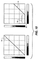
- the graphs of Figure 10 show schematically what the downshifting imaging method does to the reflectance value R value .
- the addition of the offset effectively causes a shift in the effective range of reflectance data values.
- the horizontal axis (abscissa) represents the input data code values.
- the vertical axis (ordinate) represents output data code values.
- the input/output mapping 74 has a slope of 1, mapping each input to an output at the same code value.
- the graph at the right shows a negative offset 78 applied to input/output mapping 74, resulting in an unused portion 76 of the input data, over the darker region.
- Output values are attenuated over the portion of input/output mapping 74 that is used; however, the same overall relationship (having the same slope of 1) is maintained; only the overall intensity level is reduced for the reflectance data.
- the downshifting imaging method shows pronounced improvement over the multiplicative scaling method for combining fluorescence and reflectance image data.
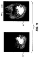
- Figure 11 shows two example FIRE images generated from the same tooth using the same illumination level.
- Image 80 on the right provided using downshifting imaging with an offset, described with respect to this third embodiment, shows marked improvement in dynamic range and contrast and improved edge definition.
- the amount of contrast i.e., intensity difference
- the offset value used.
- portions of the three different embodiments described for combining fluorescence and reflectance data can themselves be combined to obtain a FIRE image.
- drive current to light source 12 or 16a/16b can be adjusted over various settings to obtain fluorescence and reflectance images that have predetermined ranges.
- some scalar multiplication can be used to adjust these values, combined with some amount of downshifting, using the general adjustment equation: m * F value ⁇ n * R value ⁇ offset
- the image contrast enhancement achieved in the present invention is advantaged over conventional methods that use fluorescent image data only.
- image processing has been employed to optimize the data, such as to transform fluorescence data based on spectral response of the camera or of camera filters or other suitable characteristics.
- the method of the '2356 Stookey et al. disclosure, cited above performs this type of optimization, transforming fluorescence image data based on camera response.
- these conventional approaches overlook the added advantage of additional image information that the back-scattered reflectance data obtains.
- each pixel in the fluorescence image data has a corresponding pixel in the reflectance image data.
- both fluorescence and reflectance images are captured with the imaging probe in the same position and with little or no time between image captures.
- the contrast of either or both of the reflectance and fluorescence images may be improved by the use of a polarizing element.
- enamel having a highly structured composition, is sensitive to the polarization of incident light.
- Polarized light has been used to improve the sensitivity of dental imaging techniques, for example, in " Imaging Caries Lesions and Lesion Progression with Polarization Sensitive Optical Coherence Tomography" in J. Biomed Opt., October 2002; 7(4): pp. 618-27, by Fried et al.
- Polarization control can also be advantageously employed as a means to minimize specular reflection.
- Specular reflection tends to preserve the polarization state of the incident light.
- the specular reflected light is also S-polarized.
- Back-scattering tends to de-polarize or randomize the polarization of the incident light.
- incident light is S-polarized
- back-scattered light has both S- and P-polarization components. Using a polarizer and analyzer, this difference in polarization handling can be employed to help eliminate unwanted specular reflectance from the reflectance image, so that only back-scattered reflectance is obtained.
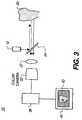
- Imaging apparatus 10 that employs a polarizer 42 in the path of illumination light.
- Polarizer 42 passes linearly polarized incident light.
- An analyzer 44 may be provided in the path of image-bearing light from tooth 20 as a means to minimize specular reflection component.
- reflectance light sensed by camera 30 or 32 is predominantly back-scattered light, that portion of the reflectance that is desirable for combination with the fluorescence image data according to the present invention.
- polarizer 42 In the case where the illumination light from light source 12 is already linearly polarized, such as from a laser, polarizer 42 is not needed; analyzer 44 would then be oriented with its polarization axis orthogonal to the polarization direction of the illumination light for rejecting specular reflection.
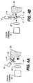
- FIG. 4B An alternate embodiment, shown in Figure 4B , employs a polarizing beamsplitter 18 (sometimes termed a polarization beamsplitter) as a polarizing element.
- polarizing beamsplitter 18 advantageously performs the functions of both the polarizer and the analyzer for image-bearing light, thus offering a more compact solution. Tracing the path of illumination and image-bearing light shows how polarizing beamsplitter 18 performs this function.
- Polarization beamsplitter 18 transmits P-polarization, as shown by the dotted arrow in Figure 4B , and reflects S-polarization, directing this light to tooth 20. Back-scattering by the tooth 20 structure depolarizes this light.
- Polarization beamsplitter 18 treats the back-scattered light in the same manner, transmitting the P-polarization and reflecting the S-polarization. The resulting P-polarized light can then be detected at camera 30 (with suitable filter as was described with reference to Figure 1 ) or color camera 32. Because specularly reflected light is S-polarized, polarization beamsplitter 18 effectively removes this specular reflective component from the light that reaches camera 30, 32.
- Polarized illumination results in further improvement in image contrast, but at the expense of light level, as can be seen from the description of Figures 4A and 4B .
- polarizer 42 One type of polarizer 42 that has particular advantages for use in the present application is the wire grid polarizer, such as those available from Moxtek Inc. of Orem, Utah and described in U.S. Patent No. 6,122,103 (Perkins et al. ).
- the wire grid polarizer exhibits good angular and color response, with relatively good transmission over the blue spectral range.
- Either or both polarizer 42 and analyzer 44 in the configuration of Figure 4A could be wire grid polarizers.
- Wire grid polarizing beamsplitters are also available, and can be used in the configuration of Figure 4B .
- the method of the present invention takes advantage of the way the tooth tissue responds to incident light of sufficient intensity, using the combination of fluorescence and light reflectance to indicate carious areas of the tooth with improved accuracy and clarity.
- the present invention offers an improvement upon existing non-invasive fluorescence detection techniques for caries.
- images that have been obtained using fluorescence only may not clearly show caries due to low contrast.
- the method of the present invention provides images having improved contrast and is, therefore, of more potential benefit to the diagnostician for identifying caries.
- the method of the present invention also provides images that can be used to detect caries in its very early incipient stages. This added capability, made possible because of the perceptible back-scattering effects for very early carious lesions, extends the usefulness of the fluorescence technique and helps in detecting caries during its reversible stages, so that fillings or other restorative strategies might not be needed.
- various types of light sources 12 could be used, with various different embodiments employing a camera or other type of image sensor.
- light source 12 might be a more complex assembly that includes one light source 16a for providing light of appropriate energy level and wavelength for exciting fluorescent emission and another light source 16b for providing illumination at different times.
- the additional light source 16b could provide light at wavelength and energy levels best suited for back-scattered reflectance imaging.
- it could provide white light illumination, or other polychromatic illumination, for capturing a white light image or polychromatic image which, when displayed side-by-side with a FIRE image, can help to identify features that might otherwise confound caries detection, such as stains or hypocalcification.
- a white light image also provides the back-scattered reflectance data that is used with the fluorescence data for generating the FIRE image.
- a suitable filter is used to transmit a selected portion of the spectrum of reflected light and to block other portions of reflected light.
- reflectance data is obtained from one color channel of the white light image, typically not from the red channel. While blue portions of the spectrum can be most favorably used for reflectance image data, there are advantages to using the green spectral range, particularly since the spectral response of sensors or a color camera is often advantaged for the green portion of the spectrum.
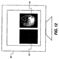
- FIRE image 64 and white-light image 54 display side-by-side on a display monitor 82.
- FIRE image 64 is generally a grayscale image.
- FIRE image 64 can be tinted with a greenish coloring. This has been found helpful for the dentist or technician operating the imaging apparatus, since it suggests fluorescence content in FIRE image 64.
Landscapes
- Health & Medical Sciences (AREA)
- Life Sciences & Earth Sciences (AREA)
- Heart & Thoracic Surgery (AREA)
- Medical Informatics (AREA)
- Physics & Mathematics (AREA)
- Dentistry (AREA)
- Biophysics (AREA)
- Pathology (AREA)
- Engineering & Computer Science (AREA)
- Biomedical Technology (AREA)
- Audiology, Speech & Language Pathology (AREA)
- Oral & Maxillofacial Surgery (AREA)
- Molecular Biology (AREA)
- Surgery (AREA)
- Animal Behavior & Ethology (AREA)
- General Health & Medical Sciences (AREA)
- Public Health (AREA)
- Veterinary Medicine (AREA)
- Dental Tools And Instruments Or Auxiliary Dental Instruments (AREA)
- Investigating, Analyzing Materials By Fluorescence Or Luminescence (AREA)
- Endoscopes (AREA)
- Measuring And Recording Apparatus For Diagnosis (AREA)
Claims (14)
- Ein Verfahren zur Bildung eines erweiterten Bildes von einem Zahn, das folgendes aufweist:a) Gewinnen von Fluoreszenzbilddaten von dem Zahn durch:(i) Leiten von einfallendem Licht auf den Zahn;(ii) Erfassen von der Fluoreszenzemission von dem Zahn;(iii) Speichern eines Fluoreszenzbilddatenwerts für jede Pixelposition in dem Fluoreszenzbild;b) Gewinnen von Reflexionsbilddaten von dem Zahn durch:(i) Leiten von einfallendem Licht auf den Zahn;(ii) Erfassen von zurückgestreutem Reflexionslicht von dem Zahn;(iii) Speichern eines Reflexionsbilddatenwerts für jede Pixelposition in dem Reflexionsbild;dadurch gekennzeichnet, dass das Verfahren weiter Folgendes aufweist:c) Kombinieren von jedem Pixel in den Fluoreszenzbilddaten mit dem entsprechenden Pixel aus den Reflexionsbilddaten durch:(i) Subtrahieren eines Offsets bzw. Versatzes zu dem Fluoreszenzbilddatenwert, um einen Offset-Reflexionsbilddatenwert zu generieren, wobei der Offset bzw. Versatz eine Differenz der Intensität zwischen der Verteilung der Fluoreszenzbilddaten und der Verteilung der Reflexionsbilddaten entspricht;(ii) nach dem Subtrahieren des Offsets, Berechnen eines erweiterten Bilddatenwerts, welcher einer Differenz zwischen dem Fluoreszenzbilddatenwert und dem Offset-Reflexionsbilddatenwert entspricht; und wobei das erweiterte Bild aus einer resultierenden Pixelanordnung von erweiterten Bilddatenwerten geformt wird.
- Das Verfahren nach Anspruch 1, das weiterhin den Schritt aufweist, das vergrößerte Bild des Zahns anzuzeigen.
- Das Verfahren nach Anspruch 1, wobei das einfallende Licht Wellenlängen zwischen etwa 300 und 500 nm aufweist.
- Das Verfahren nach Anspruch 1, wobei das Gewinnen der Fluoreszenzbilddaten, den Schritt aufweist, einen Grünfilter zu verwenden.
- Das Verfahren nach Anspruch 1, wobei das Gewinnen der Reflexionsbilddaten, den Schritt aufweist, einen Blaufilter zu verwenden.
- Das Verfahren nach Anspruch 1, wobei der Schritt des Gewinnens der Reflexionsdaten, den Gebrauch einer Kamera aufweist.
- Das Verfahren nach Anspruch 6, wobei die Kamera eine Farbkamera ist.
- Das Verfahren nach Anspruch 1, wobei die Fluoreszenzbilddaten und die Reflexionsbilddaten von unterschiedlichen Farbebenen bzw. Farbmodellen einer einzigen, Vollfarb-Bildaufnahme gewonnen werden.
- Das Verfahren nach Anspruch 1, wobei die Fluoreszenzbilddaten und die Reflexionsbilddaten aus unterschiedlichen Bildaufnahmen gewonnen werden.
- Das Verfahren nach Anspruch 2, wobei die Anzeige des erweiterten Bildes einen nicht graufarbigen Farbton aufweist.
- Das Verfahren nach Anspruch 2, wobei die Anzeige des erweiterten Bildes einen grünfarbigen Farbton aufweist.
- Das Verfahren nach Anspruch 2, wobei der Schritt des Anzeigens des erweiterten Bildes des Zahngewebes ein simultanes Anzeigen des erweiterten Bildes und einem Bild des Zahns aufweist, welches durch den Gebrauch einer polychromatischen Lichtquelle erhalten wird.
- Das Verfahren nach Anspruch 1, wobei der Schritt des Leitens von einfallendem Licht auf den Zahn, den Schritt aufweist, eine Lichtquelle zu erregen, welche aus einer Gruppe genommen wird, welche aus einem Laser, einer LED und einer Lampe besteht.
- Das Verfahren nach Anspruch 1, wobei das Gewinnen eines Reflexionsbildes das Leiten von polychromatischem, einfallendem Licht auf den Zahn aufweist.
Applications Claiming Priority (2)
| Application Number | Priority Date | Filing Date | Title |
|---|---|---|---|
| US11/468,883 US7668355B2 (en) | 2006-08-31 | 2006-08-31 | Method for detection of caries |
| PCT/US2007/018800 WO2008027323A2 (en) | 2006-08-31 | 2007-08-27 | Method for detection of caries |
Publications (2)
| Publication Number | Publication Date |
|---|---|
| EP2056712A2 EP2056712A2 (de) | 2009-05-13 |
| EP2056712B1 true EP2056712B1 (de) | 2016-10-26 |
Family
ID=39059361
Family Applications (1)
| Application Number | Title | Priority Date | Filing Date |
|---|---|---|---|
| EP07837356.0A Not-in-force EP2056712B1 (de) | 2006-08-31 | 2007-08-27 | Verfahren zum nachweis von karies |
Country Status (7)
| Country | Link |
|---|---|
| US (2) | US7668355B2 (de) |
| EP (1) | EP2056712B1 (de) |
| JP (2) | JP2010502280A (de) |
| CN (1) | CN101505655B (de) |
| ES (1) | ES2608406T3 (de) |
| HK (1) | HK1134230A1 (de) |
| WO (1) | WO2008027323A2 (de) |
Families Citing this family (93)
| Publication number | Priority date | Publication date | Assignee | Title |
|---|---|---|---|---|
| US11026768B2 (en) | 1998-10-08 | 2021-06-08 | Align Technology, Inc. | Dental appliance reinforcement |
| US9492245B2 (en) | 2004-02-27 | 2016-11-15 | Align Technology, Inc. | Method and system for providing dynamic orthodontic assessment and treatment profiles |
| US7878805B2 (en) | 2007-05-25 | 2011-02-01 | Align Technology, Inc. | Tabbed dental appliance |
| US8738394B2 (en) | 2007-11-08 | 2014-05-27 | Eric E. Kuo | Clinical data file |
| US7929151B2 (en) * | 2008-01-11 | 2011-04-19 | Carestream Health, Inc. | Intra-oral camera for diagnostic and cosmetic imaging |
| US8108189B2 (en) | 2008-03-25 | 2012-01-31 | Align Technologies, Inc. | Reconstruction of non-visible part of tooth |
| US8092215B2 (en) | 2008-05-23 | 2012-01-10 | Align Technology, Inc. | Smile designer |
| US9492243B2 (en) | 2008-05-23 | 2016-11-15 | Align Technology, Inc. | Dental implant positioning |
| US8172569B2 (en) | 2008-06-12 | 2012-05-08 | Align Technology, Inc. | Dental appliance |
| US8152518B2 (en) | 2008-10-08 | 2012-04-10 | Align Technology, Inc. | Dental positioning appliance having metallic portion |
| KR101574376B1 (ko) | 2009-01-20 | 2015-12-03 | 케어스트림 헬스 인코포레이티드 | 우식을 탐지하는 방법 및 장치 |
| US8292617B2 (en) | 2009-03-19 | 2012-10-23 | Align Technology, Inc. | Dental wire attachment |
| US8768016B2 (en) | 2009-06-19 | 2014-07-01 | Carestream Health, Inc. | Method for quantifying caries |
| US8765031B2 (en) | 2009-08-13 | 2014-07-01 | Align Technology, Inc. | Method of forming a dental appliance |
| US9235901B2 (en) * | 2009-10-14 | 2016-01-12 | Carestream Health, Inc. | Method for locating an interproximal tooth region |
| US8687859B2 (en) * | 2009-10-14 | 2014-04-01 | Carestream Health, Inc. | Method for identifying a tooth region |
| US8908936B2 (en) * | 2009-10-14 | 2014-12-09 | Carestream Health, Inc. | Method for extracting a carious lesion area |
| US20110110575A1 (en) * | 2009-11-11 | 2011-05-12 | Thiagarajar College Of Engineering | Dental caries detector |
| US20110149058A1 (en) * | 2009-12-21 | 2011-06-23 | Rongguang Liang | Intra-oral camera with polarized and unpolarized light |
| US9211166B2 (en) | 2010-04-30 | 2015-12-15 | Align Technology, Inc. | Individualized orthodontic treatment index |
| US9241774B2 (en) | 2010-04-30 | 2016-01-26 | Align Technology, Inc. | Patterned dental positioning appliance |
| US9642687B2 (en) | 2010-06-15 | 2017-05-09 | The Procter & Gamble Company | Methods for whitening teeth |
| US8571281B2 (en) | 2010-07-13 | 2013-10-29 | Carestream Health, Inc. | Dental shade mapping |
| US8208704B2 (en) * | 2010-07-13 | 2012-06-26 | Carestream Health, Inc. | Dental shade mapping |
| US9436868B2 (en) * | 2010-09-10 | 2016-09-06 | Dimensional Photonics International, Inc. | Object classification for measured three-dimensional object scenes |
| EP2476368A1 (de) | 2011-01-17 | 2012-07-18 | Carestream Health, Inc. | Intraorale Kamera mit polarisiertem und nicht polarisiertem Licht |
| US9299172B2 (en) | 2011-07-28 | 2016-03-29 | Koninklijke Philips N.V. | Image generation apparatus |
| US9486141B2 (en) | 2011-08-09 | 2016-11-08 | Carestream Health, Inc. | Identification of dental caries in live video images |
| US9403238B2 (en) | 2011-09-21 | 2016-08-02 | Align Technology, Inc. | Laser cutting |
| US9375300B2 (en) | 2012-02-02 | 2016-06-28 | Align Technology, Inc. | Identifying forces on a tooth |
| JP2013169256A (ja) * | 2012-02-20 | 2013-09-02 | Osamu Motoyama | 歯科ハンドピース用の映像取得機器、歯科ハンドピース用撮像装置、歯科ハンドピース、及び歯科ハンドピースシステム |
| US9220580B2 (en) | 2012-03-01 | 2015-12-29 | Align Technology, Inc. | Determining a dental treatment difficulty |
| FR2988473B1 (fr) * | 2012-03-22 | 2014-04-18 | Spectralys Innovation | Procede et appareil de caracterisation d'echantillons par mesure de la diffusion lumineuse et de la fluorescence. |
| JP5835669B2 (ja) * | 2012-04-03 | 2015-12-24 | アドバンストヘルスケア株式会社 | 撮影システム |
| US9414897B2 (en) | 2012-05-22 | 2016-08-16 | Align Technology, Inc. | Adjustment of tooth position in a virtual dental model |
| JP5974640B2 (ja) * | 2012-06-01 | 2016-08-23 | ソニー株式会社 | 歯用装置及び情報処理装置 |
| US10772506B2 (en) | 2014-07-07 | 2020-09-15 | Align Technology, Inc. | Apparatus for dental confocal imaging |
| US9675430B2 (en) | 2014-08-15 | 2017-06-13 | Align Technology, Inc. | Confocal imaging apparatus with curved focal surface |
| US9610141B2 (en) | 2014-09-19 | 2017-04-04 | Align Technology, Inc. | Arch expanding appliance |
| US10449016B2 (en) | 2014-09-19 | 2019-10-22 | Align Technology, Inc. | Arch adjustment appliance |
| US9870613B2 (en) * | 2014-11-05 | 2018-01-16 | Carestream Health, Inc. | Detection of tooth condition using reflectance images with red and green fluorescence |
| WO2016073569A2 (en) | 2014-11-05 | 2016-05-12 | Carestream Health, Inc. | Video detection of tooth condition using green and red fluorescence |
| US9744001B2 (en) | 2014-11-13 | 2017-08-29 | Align Technology, Inc. | Dental appliance with cavity for an unerupted or erupting tooth |
| CN106999020A (zh) | 2014-12-17 | 2017-08-01 | 卡尔斯特里姆保健公司 | 口腔内3d荧光成像 |
| US10504386B2 (en) | 2015-01-27 | 2019-12-10 | Align Technology, Inc. | Training method and system for oral-cavity-imaging-and-modeling equipment |
| US9846937B1 (en) * | 2015-03-06 | 2017-12-19 | Aseem Sharma | Method for medical image analysis and manipulation |
| US9547903B2 (en) | 2015-04-16 | 2017-01-17 | Carestream Health, Inc. | Method for quantifying caries |
| US10248883B2 (en) | 2015-08-20 | 2019-04-02 | Align Technology, Inc. | Photograph-based assessment of dental treatments and procedures |
| US11931222B2 (en) | 2015-11-12 | 2024-03-19 | Align Technology, Inc. | Dental attachment formation structures |
| US11554000B2 (en) | 2015-11-12 | 2023-01-17 | Align Technology, Inc. | Dental attachment formation structure |
| US11596502B2 (en) | 2015-12-09 | 2023-03-07 | Align Technology, Inc. | Dental attachment placement structure |
| US11103330B2 (en) | 2015-12-09 | 2021-08-31 | Align Technology, Inc. | Dental attachment placement structure |
| KR102471937B1 (ko) * | 2016-02-05 | 2022-11-29 | (주)바텍이우홀딩스 | X선 영상을 이용한 치아 우식 가능성 판단 방법 |
| US10470847B2 (en) | 2016-06-17 | 2019-11-12 | Align Technology, Inc. | Intraoral appliances with sensing |
| EP3471653B1 (de) | 2016-06-17 | 2021-12-22 | Align Technology, Inc. | Leistungsüberwachung einer kieferorthopädischen vorrichtung |
| US10380212B2 (en) | 2016-07-27 | 2019-08-13 | Align Technology, Inc. | Methods and apparatuses for forming a three-dimensional volumetric model of a subject's teeth |
| US10507087B2 (en) | 2016-07-27 | 2019-12-17 | Align Technology, Inc. | Methods and apparatuses for forming a three-dimensional volumetric model of a subject's teeth |
| CN117257492A (zh) | 2016-11-04 | 2023-12-22 | 阿莱恩技术有限公司 | 用于牙齿图像的方法和装置 |
| WO2018102702A1 (en) | 2016-12-02 | 2018-06-07 | Align Technology, Inc. | Dental appliance features for speech enhancement |
| EP3824843A1 (de) | 2016-12-02 | 2021-05-26 | Align Technology, Inc. | Palatale expander und verfahren zur erweiterung des gaumens |
| US11376101B2 (en) | 2016-12-02 | 2022-07-05 | Align Technology, Inc. | Force control, stop mechanism, regulating structure of removable arch adjustment appliance |
| AU2017366755B2 (en) | 2016-12-02 | 2022-07-28 | Align Technology, Inc. | Methods and apparatuses for customizing rapid palatal expanders using digital models |
| US10548700B2 (en) | 2016-12-16 | 2020-02-04 | Align Technology, Inc. | Dental appliance etch template |
| US10456043B2 (en) | 2017-01-12 | 2019-10-29 | Align Technology, Inc. | Compact confocal dental scanning apparatus |
| US10779718B2 (en) | 2017-02-13 | 2020-09-22 | Align Technology, Inc. | Cheek retractor and mobile device holder |
| WO2018183358A1 (en) | 2017-03-27 | 2018-10-04 | Align Technology, Inc. | Apparatuses and methods assisting in dental therapies |
| US10613515B2 (en) | 2017-03-31 | 2020-04-07 | Align Technology, Inc. | Orthodontic appliances including at least partially un-erupted teeth and method of forming them |
| MX2019012362A (es) * | 2017-04-24 | 2020-02-17 | Colgate Palmolive Co | Metodos de supervision de manchas blancas en dientes. |
| US11045283B2 (en) | 2017-06-09 | 2021-06-29 | Align Technology, Inc. | Palatal expander with skeletal anchorage devices |
| CN110769777B (zh) | 2017-06-16 | 2023-08-11 | 阿莱恩技术有限公司 | 牙齿类型和萌出状态的自动检测 |
| KR102573669B1 (ko) * | 2017-06-21 | 2023-09-04 | 코닌클리케 필립스 엔.브이. | 조기 우식 검출을 위한 방법 및 장치 |
| US10639134B2 (en) | 2017-06-26 | 2020-05-05 | Align Technology, Inc. | Biosensor performance indicator for intraoral appliances |
| US10885521B2 (en) | 2017-07-17 | 2021-01-05 | Align Technology, Inc. | Method and apparatuses for interactive ordering of dental aligners |
| CN114903623A (zh) | 2017-07-21 | 2022-08-16 | 阿莱恩技术有限公司 | 颚轮廓锚固 |
| CN115462921A (zh) | 2017-07-27 | 2022-12-13 | 阿莱恩技术有限公司 | 牙齿着色、透明度和上釉 |
| EP4278957A3 (de) | 2017-07-27 | 2024-01-24 | Align Technology, Inc. | System und verfahren zur verarbeitung eines orthodontischen ausrichters mittels optischer kohärenztomographie |
| US20190046297A1 (en) * | 2017-08-11 | 2019-02-14 | Align Technology, Inc. | Devices and systems for creation of attachments for use with dental appliances and changeable shaped attachments |
| US11116605B2 (en) | 2017-08-15 | 2021-09-14 | Align Technology, Inc. | Buccal corridor assessment and computation |
| US11123156B2 (en) | 2017-08-17 | 2021-09-21 | Align Technology, Inc. | Dental appliance compliance monitoring |
| US10813720B2 (en) | 2017-10-05 | 2020-10-27 | Align Technology, Inc. | Interproximal reduction templates |
| CN114939001A (zh) | 2017-10-27 | 2022-08-26 | 阿莱恩技术有限公司 | 替代咬合调整结构 |
| EP3703608B1 (de) | 2017-10-31 | 2023-08-30 | Align Technology, Inc. | Ermittlung eines zahnärztlichen gerätes mit selektiver okklusaler belastung und kontrollierter interkuspidation |
| US11096763B2 (en) | 2017-11-01 | 2021-08-24 | Align Technology, Inc. | Automatic treatment planning |
| WO2019100022A1 (en) | 2017-11-17 | 2019-05-23 | Align Technology, Inc. | Orthodontic retainers |
| CN114948315B (zh) | 2017-11-30 | 2024-08-27 | 阿莱恩技术有限公司 | 用于监测口腔矫治器的传感器 |
| US11432908B2 (en) | 2017-12-15 | 2022-09-06 | Align Technology, Inc. | Closed loop adaptive orthodontic treatment methods and apparatuses |
| US10980613B2 (en) | 2017-12-29 | 2021-04-20 | Align Technology, Inc. | Augmented reality enhancements for dental practitioners |
| KR20200115580A (ko) | 2018-01-26 | 2020-10-07 | 얼라인 테크널러지, 인크. | 구강 내 진단 스캔 및 추적 |
| KR102085572B1 (ko) * | 2018-02-13 | 2020-03-06 | 서울대학교산학협력단 | 우식치아 검출장치 및 검출방법 |
| US11937991B2 (en) | 2018-03-27 | 2024-03-26 | Align Technology, Inc. | Dental attachment placement structure |
| AU2019251474B2 (en) | 2018-04-11 | 2024-09-12 | Align Technology, Inc. | Releasable palatal expanders |
| KR102197111B1 (ko) | 2019-05-08 | 2020-12-30 | 경북대학교 산학협력단 | 치아 표면상의 접착잔여물 측정 시스템 및 접착잔여물 측정방법 |
| KR102434573B1 (ko) * | 2020-04-24 | 2022-08-22 | (주) 휴비츠 | 구강용 3d 컬러 스캐너 |
Family Cites Families (30)
| Publication number | Priority date | Publication date | Assignee | Title |
|---|---|---|---|---|
| US2286779A (en) * | 1940-04-05 | 1942-06-16 | Eastman Kodak Co | Photomechanical color reproduction |
| SE442817B (sv) * | 1981-04-01 | 1986-02-03 | Hans Ingmar Bjelkhagen | Anordning for att okulert kunna faststella en diskrepans i en tandytas luminiscensformaga |
| US4479499A (en) * | 1982-01-29 | 1984-10-30 | Alfano Robert R | Method and apparatus for detecting the presence of caries in teeth using visible light |
| CH672722A5 (de) * | 1986-06-24 | 1989-12-29 | Marco Brandestini | |
| DE4111903A1 (de) * | 1991-04-12 | 1992-10-15 | Bayer Ag | Spektroskopiekorrelierte licht-rastermikroskopie |
| DE4200741C2 (de) * | 1992-01-14 | 2000-06-15 | Kaltenbach & Voigt | Einrichtung zum Erkennen von Karies an Zähnen |
| JPH0838465A (ja) * | 1994-07-29 | 1996-02-13 | Shimadzu Corp | X線診断装置 |
| US5759030A (en) * | 1996-01-02 | 1998-06-02 | Lj Laboratories, L.L.C. | Method for determing optical characteristics of teeth |
| US5854063A (en) * | 1996-01-16 | 1998-12-29 | The State Of Oregon Acting By And Through The State Board Of Higher Education On Behalf Of Oregon State University | Method and apparatus for spectrophotometric observation of plants |
| US6571118B1 (en) * | 1998-05-04 | 2003-05-27 | Board Of Regents, The University Of Texas System | Combined fluorescence and reflectance spectroscopy |
| US6206691B1 (en) * | 1998-05-20 | 2001-03-27 | Shade Analyzing Technologies, Inc. | System and methods for analyzing tooth shades |
| DE19825021A1 (de) * | 1998-06-04 | 1999-12-09 | Kaltenbach & Voigt | Verfahren und Vorrichtung zum Erkennen von Karies, Plaque, Konkrementen oder bakteriellem Befall an Zähnen |
| NL1012012C2 (nl) * | 1999-05-10 | 2000-11-23 | Inspektor Res Systems B V | Werkwijze en inrichting voor het bepalen van cariÙsactiviteit van een carieuze laesie in een tand. |
| US6122103A (en) * | 1999-06-22 | 2000-09-19 | Moxtech | Broadband wire grid polarizer for the visible spectrum |
| DE60021417T2 (de) * | 1999-12-08 | 2006-05-24 | X-Rite, Inc., Grandville | Optisches Meßgerät |
| JP3731814B2 (ja) * | 2001-05-07 | 2006-01-05 | 富士写真フイルム株式会社 | 蛍光画像表示装置 |
| FR2825260B1 (fr) | 2001-06-01 | 2004-08-20 | Centre Nat Rech Scient | Procede et dispositif de detection de caries dentaires |
| DE102004001856B4 (de) * | 2003-01-14 | 2019-05-23 | J. Morita Mfg. Corp. | Bilderstellungsgerät für Diagnosezwecke |
| US20040202356A1 (en) * | 2003-04-10 | 2004-10-14 | Stookey George K. | Optical detection of dental caries |
| EP1644867B1 (de) | 2003-04-18 | 2010-08-11 | Medispectra, Inc. | System und Diagnoseverfahren zur optischen Detektion von verdächtigen Stellen einer Gewebeprobe |
| US20040254478A1 (en) * | 2003-05-22 | 2004-12-16 | De Josselin De Jong Elbert | Fluorescence filter for tissue examination and imaging |
| US7064830B2 (en) * | 2003-06-12 | 2006-06-20 | Eastman Kodak Company | Dental color imaging system |
| FR2856546B1 (fr) | 2003-06-17 | 2005-11-04 | Centre Nat Rech Scient | Procede et dispositif d'acquisition et de traitement d'images d'un objet tel qu'une dent |
| US7241746B2 (en) * | 2003-08-06 | 2007-07-10 | Regena Therapeutics, Lc | Method and composition for treating periodontal disease |
| JP2005110828A (ja) * | 2003-10-06 | 2005-04-28 | Omega Wave Kk | 歯科用診断装置 |
| JP2005319116A (ja) * | 2004-05-10 | 2005-11-17 | Pentax Corp | 蛍光観察内視鏡装置 |
| US7796243B2 (en) * | 2004-06-09 | 2010-09-14 | National Research Council Of Canada | Detection and monitoring of changes in mineralized tissues or calcified deposits by optical coherence tomography and Raman spectroscopy |
| JP2006006435A (ja) * | 2004-06-23 | 2006-01-12 | Fuji Photo Film Co Ltd | 画像表示方法および装置並びにプログラム |
| WO2006023424A2 (en) * | 2004-08-13 | 2006-03-02 | Biolase Technology, Inc. | Method and apparatus for detecting dental caries |
| US7596253B2 (en) * | 2005-10-31 | 2009-09-29 | Carestream Health, Inc. | Method and apparatus for detection of caries |
-
2006
- 2006-08-31 US US11/468,883 patent/US7668355B2/en not_active Expired - Fee Related
-
2007
- 2007-08-27 WO PCT/US2007/018800 patent/WO2008027323A2/en active Application Filing
- 2007-08-27 ES ES07837356.0T patent/ES2608406T3/es active Active
- 2007-08-27 CN CN2007800312124A patent/CN101505655B/zh not_active Expired - Fee Related
- 2007-08-27 EP EP07837356.0A patent/EP2056712B1/de not_active Not-in-force
- 2007-08-27 JP JP2009526661A patent/JP2010502280A/ja active Pending
-
2009
- 2009-11-11 HK HK09110523.6A patent/HK1134230A1/xx not_active IP Right Cessation
-
2010
- 2010-01-25 US US12/692,787 patent/US8447083B2/en not_active Expired - Fee Related
-
2014
- 2014-10-10 JP JP2014208769A patent/JP5977302B2/ja not_active Expired - Fee Related
Also Published As
| Publication number | Publication date |
|---|---|
| JP2015016364A (ja) | 2015-01-29 |
| WO2008027323A3 (en) | 2008-05-08 |
| CN101505655A (zh) | 2009-08-12 |
| US8447083B2 (en) | 2013-05-21 |
| US7668355B2 (en) | 2010-02-23 |
| HK1134230A1 (en) | 2010-04-23 |
| US20080056551A1 (en) | 2008-03-06 |
| WO2008027323A2 (en) | 2008-03-06 |
| JP2010502280A (ja) | 2010-01-28 |
| JP5977302B2 (ja) | 2016-08-24 |
| ES2608406T3 (es) | 2017-04-10 |
| US20100128959A1 (en) | 2010-05-27 |
| CN101505655B (zh) | 2011-11-16 |
| EP2056712A2 (de) | 2009-05-13 |
Similar Documents
| Publication | Publication Date | Title |
|---|---|---|
| EP2056712B1 (de) | Verfahren zum nachweis von karies | |
| US9247241B2 (en) | Method and apparatus for detection of caries | |
| EP2010045B1 (de) | Optische erkennung von karies | |
| US10070791B2 (en) | Apparatus for caries detection | |
| US8224045B2 (en) | System for early detection of dental caries | |
| US7702139B2 (en) | Apparatus for caries detection |
Legal Events
| Date | Code | Title | Description |
|---|---|---|---|
| PUAI | Public reference made under article 153(3) epc to a published international application that has entered the european phase |
Free format text: ORIGINAL CODE: 0009012 |
|
| 17P | Request for examination filed |
Effective date: 20090129 |
|
| AK | Designated contracting states |
Kind code of ref document: A2 Designated state(s): AT BE BG CH CY CZ DE DK EE ES FI FR GB GR HU IE IS IT LI LT LU LV MC MT NL PL PT RO SE SI SK TR |
|
| AX | Request for extension of the european patent |
Extension state: AL BA HR MK RS |
|
| DAX | Request for extension of the european patent (deleted) | ||
| R17D | Deferred search report published (corrected) |
Effective date: 20080508 |
|
| RBV | Designated contracting states (corrected) |
Designated state(s): DE ES FI FR GB IT |
|
| 17Q | First examination report despatched |
Effective date: 20121205 |
|
| GRAP | Despatch of communication of intention to grant a patent |
Free format text: ORIGINAL CODE: EPIDOSNIGR1 |
|
| INTG | Intention to grant announced |
Effective date: 20160510 |
|
| GRAS | Grant fee paid |
Free format text: ORIGINAL CODE: EPIDOSNIGR3 |
|
| GRAA | (expected) grant |
Free format text: ORIGINAL CODE: 0009210 |
|
| AK | Designated contracting states |
Kind code of ref document: B1 Designated state(s): DE ES FI FR GB IT |
|
| REG | Reference to a national code |
Ref country code: GB Ref legal event code: FG4D |
|
| REG | Reference to a national code |
Ref country code: DE Ref legal event code: R096 Ref document number: 602007048494 Country of ref document: DE |
|
| REG | Reference to a national code |
Ref country code: ES Ref legal event code: FG2A Ref document number: 2608406 Country of ref document: ES Kind code of ref document: T3 Effective date: 20170410 |
|
| REG | Reference to a national code |
Ref country code: FR Ref legal event code: PLFP Year of fee payment: 11 |
|
| REG | Reference to a national code |
Ref country code: DE Ref legal event code: R097 Ref document number: 602007048494 Country of ref document: DE |
|
| PLBE | No opposition filed within time limit |
Free format text: ORIGINAL CODE: 0009261 |
|
| STAA | Information on the status of an ep patent application or granted ep patent |
Free format text: STATUS: NO OPPOSITION FILED WITHIN TIME LIMIT |
|
| 26N | No opposition filed |
Effective date: 20170727 |
|
| PGFP | Annual fee paid to national office [announced via postgrant information from national office to epo] |
Ref country code: LT Payment date: 20170904 Year of fee payment: 11 |
|
| REG | Reference to a national code |
Ref country code: GB Ref legal event code: 732E Free format text: REGISTERED BETWEEN 20180118 AND 20180124 |
|
| REG | Reference to a national code |
Ref country code: GB Ref legal event code: 732E Free format text: REGISTERED BETWEEN 20180125 AND 20180131 Ref country code: DE Ref legal event code: R082 Ref document number: 602007048494 Country of ref document: DE Representative=s name: WAGNER & GEYER PARTNERSCHAFT MBB PATENT- UND R, DE Ref country code: DE Ref legal event code: R081 Ref document number: 602007048494 Country of ref document: DE Owner name: CARESTREAM DENTAL TECHNOLOGY TOPCO LIMITED, GB Free format text: FORMER OWNER: CARESTREAM HEALTH, INC., ROCHESTER, N. Y., US |
|
| REG | Reference to a national code |
Ref country code: FR Ref legal event code: TP Owner name: CARESTREAM DENTAL TECHNOLOGY TOPCO LIMITED, GB Effective date: 20180320 |
|
| REG | Reference to a national code |
Ref country code: FR Ref legal event code: PLFP Year of fee payment: 12 |
|
| PG25 | Lapsed in a contracting state [announced via postgrant information from national office to epo] |
Ref country code: IT Free format text: LAPSE BECAUSE OF NON-PAYMENT OF DUE FEES Effective date: 20180827 |
|
| REG | Reference to a national code |
Ref country code: ES Ref legal event code: FD2A Effective date: 20190918 |
|
| PG25 | Lapsed in a contracting state [announced via postgrant information from national office to epo] |
Ref country code: ES Free format text: LAPSE BECAUSE OF NON-PAYMENT OF DUE FEES Effective date: 20180828 |
|
| PGFP | Annual fee paid to national office [announced via postgrant information from national office to epo] |
Ref country code: DE Payment date: 20190715 Year of fee payment: 13 Ref country code: FR Payment date: 20190717 Year of fee payment: 13 Ref country code: FI Payment date: 20190726 Year of fee payment: 13 |
|
| PGFP | Annual fee paid to national office [announced via postgrant information from national office to epo] |
Ref country code: GB Payment date: 20190728 Year of fee payment: 13 |
|
| REG | Reference to a national code |
Ref country code: DE Ref legal event code: R119 Ref document number: 602007048494 Country of ref document: DE |
|
| REG | Reference to a national code |
Ref country code: FI Ref legal event code: MAE |
|
| GBPC | Gb: european patent ceased through non-payment of renewal fee |
Effective date: 20200827 |
|
| PG25 | Lapsed in a contracting state [announced via postgrant information from national office to epo] |
Ref country code: FI Free format text: LAPSE BECAUSE OF NON-PAYMENT OF DUE FEES Effective date: 20200827 |
|
| PG25 | Lapsed in a contracting state [announced via postgrant information from national office to epo] |
Ref country code: FR Free format text: LAPSE BECAUSE OF NON-PAYMENT OF DUE FEES Effective date: 20200831 Ref country code: DE Free format text: LAPSE BECAUSE OF NON-PAYMENT OF DUE FEES Effective date: 20210302 |
|
| PG25 | Lapsed in a contracting state [announced via postgrant information from national office to epo] |
Ref country code: GB Free format text: LAPSE BECAUSE OF NON-PAYMENT OF DUE FEES Effective date: 20200827 |