EP2056443B1 - Vorrichtung zur Steuerung der Stromerzeugung in Fahrzeugen - Google Patents
Vorrichtung zur Steuerung der Stromerzeugung in Fahrzeugen Download PDFInfo
- Publication number
- EP2056443B1 EP2056443B1 EP08017314.9A EP08017314A EP2056443B1 EP 2056443 B1 EP2056443 B1 EP 2056443B1 EP 08017314 A EP08017314 A EP 08017314A EP 2056443 B1 EP2056443 B1 EP 2056443B1
- Authority
- EP
- European Patent Office
- Prior art keywords
- signal
- field current
- voltage
- section
- generator
- Prior art date
- Legal status (The legal status is an assumption and is not a legal conclusion. Google has not performed a legal analysis and makes no representation as to the accuracy of the status listed.)
- Ceased
Links
Images
Classifications
-
- H—ELECTRICITY
- H02—GENERATION; CONVERSION OR DISTRIBUTION OF ELECTRIC POWER
- H02P—CONTROL OR REGULATION OF ELECTRIC MOTORS, ELECTRIC GENERATORS OR DYNAMO-ELECTRIC CONVERTERS; CONTROLLING TRANSFORMERS, REACTORS OR CHOKE COILS
- H02P9/00—Arrangements for controlling electric generators for the purpose of obtaining a desired output
- H02P9/14—Arrangements for controlling electric generators for the purpose of obtaining a desired output by variation of field
- H02P9/26—Arrangements for controlling electric generators for the purpose of obtaining a desired output by variation of field using discharge tubes or semiconductor devices
- H02P9/30—Arrangements for controlling electric generators for the purpose of obtaining a desired output by variation of field using discharge tubes or semiconductor devices using semiconductor devices
- H02P9/305—Arrangements for controlling electric generators for the purpose of obtaining a desired output by variation of field using discharge tubes or semiconductor devices using semiconductor devices controlling voltage
-
- H—ELECTRICITY
- H02—GENERATION; CONVERSION OR DISTRIBUTION OF ELECTRIC POWER
- H02J—CIRCUIT ARRANGEMENTS OR SYSTEMS FOR SUPPLYING OR DISTRIBUTING ELECTRIC POWER; SYSTEMS FOR STORING ELECTRIC ENERGY
- H02J7/00—Circuit arrangements for charging or depolarising batteries or for supplying loads from batteries
- H02J7/14—Circuit arrangements for charging or depolarising batteries or for supplying loads from batteries for charging batteries from dynamo-electric generators driven at varying speed, e.g. on vehicle
- H02J7/16—Regulation of the charging current or voltage by variation of field
- H02J7/24—Regulation of the charging current or voltage by variation of field using discharge tubes or semiconductor devices
- H02J7/243—Regulation of the charging current or voltage by variation of field using discharge tubes or semiconductor devices with on/off action
-
- H—ELECTRICITY
- H02—GENERATION; CONVERSION OR DISTRIBUTION OF ELECTRIC POWER
- H02P—CONTROL OR REGULATION OF ELECTRIC MOTORS, ELECTRIC GENERATORS OR DYNAMO-ELECTRIC CONVERTERS; CONTROLLING TRANSFORMERS, REACTORS OR CHOKE COILS
- H02P9/00—Arrangements for controlling electric generators for the purpose of obtaining a desired output
- H02P9/02—Details of the control
-
- H—ELECTRICITY
- H02—GENERATION; CONVERSION OR DISTRIBUTION OF ELECTRIC POWER
- H02P—CONTROL OR REGULATION OF ELECTRIC MOTORS, ELECTRIC GENERATORS OR DYNAMO-ELECTRIC CONVERTERS; CONTROLLING TRANSFORMERS, REACTORS OR CHOKE COILS
- H02P9/00—Arrangements for controlling electric generators for the purpose of obtaining a desired output
- H02P9/48—Arrangements for obtaining a constant output value at varying speed of the generator, e.g. on vehicle
-
- H—ELECTRICITY
- H02—GENERATION; CONVERSION OR DISTRIBUTION OF ELECTRIC POWER
- H02P—CONTROL OR REGULATION OF ELECTRIC MOTORS, ELECTRIC GENERATORS OR DYNAMO-ELECTRIC CONVERTERS; CONTROLLING TRANSFORMERS, REACTORS OR CHOKE COILS
- H02P2101/00—Special adaptation of control arrangements for generators
- H02P2101/45—Special adaptation of control arrangements for generators for motor vehicles, e.g. car alternators
-
- Y—GENERAL TAGGING OF NEW TECHNOLOGICAL DEVELOPMENTS; GENERAL TAGGING OF CROSS-SECTIONAL TECHNOLOGIES SPANNING OVER SEVERAL SECTIONS OF THE IPC; TECHNICAL SUBJECTS COVERED BY FORMER USPC CROSS-REFERENCE ART COLLECTIONS [XRACs] AND DIGESTS
- Y02—TECHNOLOGIES OR APPLICATIONS FOR MITIGATION OR ADAPTATION AGAINST CLIMATE CHANGE
- Y02T—CLIMATE CHANGE MITIGATION TECHNOLOGIES RELATED TO TRANSPORTATION
- Y02T10/00—Road transport of goods or passengers
- Y02T10/60—Other road transportation technologies with climate change mitigation effect
- Y02T10/70—Energy storage systems for electromobility, e.g. batteries
Definitions
- the present invention relates to an apparatus for controlling generation of power in vehicles, which controls output voltage of a generator mounted on a vehicle such as a car and a motor truck.
- a method in which terminal voltage of a field coil is used as a signal.
- the signal indicates an operation state of a generator (e.g. an operating rate of the generator) of a vehicle and is transmitted to an external control unit (ECU) which is disposed outside the generator.
- ECU external control unit
- This method is disclosed, for example, in Japanese Examined Utility Model Application Publication No. 6-19359 .
- a control signal is used as the above-described signal.
- the control signal operates switching elements of a power generation control apparatus to control a field current. This method is disclosed, for example, in Japanese Unexamined Patent Application Publication No. 9-84398 .
- the ECU receives the transmitted signal (in the form of a duty signal), detects the applied electrical load based on the variation in the signal, and controls a throttle valve to stabilize idling engine speed.
- power generation control apparatuses having the following functions have grown in number.
- field current of a generator of a vehicle is gradually increased to prevent the load of the generator associated with an engine from sharply increasing when electrical loads are applied.
- the maximum value of the field current of the generator is restricted in order to decrease the maximum value of the load of the generator.
- these functions for suppressing field current are activated, when electrical loads are applied, the field current is gradually increased, or the maximum value of the field current is restricted to a predetermined value (e.g. 80 %). Therefore, the variation of the signal transmitted to the ECU (i.e. the variation of the duty value) becomes small, or the value of the signal does not reach a threshold (e.g.
- the present invention has been made in consideration of the foregoing conventional situation, and an object of the present invention is to provide an apparatus for controlling generation of power in vehicles which can accurately detect an operating state of a generator of a vehicle (i.e., the operating state is a state where electrical loads are applied) and stabilize idling engine speed.
- the present invention provides, as one aspect, an apparatus for controlling generation of power in vehicles which include a generator having a field winding and a battery, characterized by comprising: a voltage comparing section that compares either output voltage of the generator or terminal voltage of the battery with a predetermined regulation voltage; a field current controlling section that controls field current passing through the field winding of the generator; a field current suppressing section that drives the field current controlling section based on a comparison result of the voltage comparing section to suppress the field current; and an external output terminal that transmits either a first signal outputted from the voltage comparing section and inputted into the field current suppressing section or a second signal corresponding to the first signal.
- an external control unit can accurately detect the operating state of the generator when the electrical load varies in amount (i.e., the operating state is a state where the electrical loads are applied).
- the external control unit can perform control of idling engine speed (control of a throttle valve) in response to the applied electrical load to stabilize the idling engine speed.
- the apparatus further comprises a signal equalizing section which equalizes the first or second signal.
- An output signal of the voltage comparing section fluctuates due to engine speed, intermittent electrical loads which are constantly operated, or the like. However, since the output signal is equalized, the operation state of the generator when the electrical loads are applied (i.e. the state where the electrical loads are applied) can be detected more accurately.
- the apparatus further comprises a pulse signal generating section that generates a pulse signal corresponding to the first or second signal.
- the pulse signal is transmitted via the external output terminal. Since the signal transmitted from the external output terminal is a pulse signal, the signal can be transmitted and received between the apparatus and the external control unit by using serial communication such as LIN communication. Therefore, when comparing the above-described transmission with any direct transmission of voltage values, the above-described transmission improves reliability of the communication and facilitates sharing a signal line when other information is transmitted.
- the signal equalizing section performs equalization for a period of time longer than a control period of ignition of the vehicle.
- the period of time is preferably more than 20 ms. Accordingly, the influence of ignition noise generated during idling can be eliminated, thereby allowing the operation state of the generator (i.e. the state where the electrical loads are applied) to be more accurately detected and allowing the idling engine speed to be more stable.
- the field current suppressing section gradually increases the field current or restricts the maximum value of the field current.
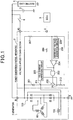
- FIG. 1 is a diagram showing a configuration of a power generation control apparatus for vehicles according to an embodiment of the present invention.
- FIG.1 shows a connection diagram for a generator 1, a power generation control apparatus 2, a battery 3, electric loads 4, an ECU 5, and an ignition key 6, which are installed in a vehicle.
- the power generation control apparatus 2 controls the voltage at an output terminal (called B terminal) of the generator 1 so as to make the voltage agree with a predetermined regulation voltage (e.g. 14 V).
- the power generation control apparatus 2 has not only the B terminal but also an ignition terminal (IG terminal), a communication terminal (called C terminal), and a ground terminal (called E terminal).
- the B terminal is connected to the battery 3 and various electric loads 4 via a predetermined charging line.
- the IG terminal is connected to a positive-pole terminal of the battery 3 via the ignition key 6.
- the C terminal is connected to the ECU 5 serving as an external control unit which is disposed outside the generator 1 and the power generation control apparatus 2.
- the E terminal is connected to a frame of the generator 1. Note that although the power generation control apparatus 2 and the generator 1 are depicted in FIG. 1 side by side, the power generation control apparatus 2 is contained in the generator 1 in practice. In addition, the generator 1 shares the B terminal and the E terminal with the power generation control apparatus 2.
- the generator 1 comprises a three-phase stator winding 101, a field winding 102, and a rectifier circuit 103.
- the stator winding 101 is included in a stator.
- the field winding 102 is included in a rotor.
- the rectifier circuit 103 is arranged in order to full-wave rectify the three-phase output of the stator winding 101.
- the output voltage of the generator 1 is controlled in such a manner that the power generation control apparatus 2 appropriately turns on and off electric current passing through the field winding 102.
- the power generation control apparatus 2 comprises a free-wheeling diode 201, a switching element 202, an AND circuit 203, a voltage comparator 204, a field current suppressing circuit 205, a reference voltage generation circuit 206, and resistors 207, 208, 209, and 213.
- the switching element 202 is electrically connected in series with the field winding 102 and the resistor 213. When the switching element 202 is ON, field current passes through the field winding 102 and the resistor 213.
- the free-wheeling diode 201 is connected in parallel with the field winding 102. When the switching element 202 is OFF, the field current returns through the free-wheeling diode 201.
- the reference voltage generation circuit 206 generates a reference voltage corresponding to a predetermined regulation voltage in order to adjust the output voltage of the generator 1 to the regulation voltage.
- the reference voltage generated by the reference voltage generation circuit 206 is applied to a positive input terminal of the voltage comparator 204.
- the B terminal of the generator 1 is connected to a voltage divider circuit which is composed of the resistors 207 and 208.
- the output voltage of the generator 1 is divided by the voltage divider circuit.
- the divided voltage is applied to a negative input terminal of the voltage comparator 204.
- the reference voltage generation circuit 206 generates the reference voltage by multiplying the regulation voltage by the division ratio of the voltage divider circuit. Note that the reference voltage generated by the reference voltage generation circuit 206 not only is used as a fixed value but also may be properly changed in response to the state of the power generation of the generator 1 or based on a regulation voltage setting signal sent from the ECU 5.
- the voltage comparator 204 compares the reference voltage applied to the positive input terminal with the divided output voltage of the generator 1 applied to the negative input terminal through the voltage divider circuit composed of the resistors 207 and 208. When the divided output voltage is lower than the reference voltage, the voltage comparator 204 outputs a high-level signal. Conversely, when the divided output voltage is equal to or higher than the reference voltage, the voltage comparator 204 outputs a low-level signal.
- the output signal of the voltage comparator 204 is inputted into one input terminal of the AND circuit 203.
- An output signal of the field current suppressing circuit 205 is inputted into the other input terminal of the AND circuit 203.
- the field current suppressing circuit 205 suppresses the sharp increase of the field current passing through the field winding 102 and restricts the maximum value of the field current.
- the field current suppressing circuit 205 performs these operations while monitoring the voltage at a connection point P1 between the switching element 202 and the field winding 102 and the voltage at a connection point P2 between the switching element 202 and the resistor 213 (output side of the switching element 202).
- the field current suppressing circuit 205 detects the voltage at the connection point P1 between the switching element 202 and the field winding 102, and generates a signal having on-duty (on-duty ratio) obtained by increasing on-duty of the detected voltage with a predetermined increasing rate.
- the field current suppressing circuit 205 outputs the generated signal to the other input terminal of the AND circuit 203.
- the AND circuit 203 performs AND operation between two signals inputted into the two input terminals thereof to obtain an AND signal, and outputs the AND signal to be used as a driving signal to the switching element 202. While the driving signal is at the high level, the switching element 202 is in the ON state. While the driving signal is at the low level, the switching element 202 is in the OFF state.
- the field current suppressing circuit 205 When a large amount of electric load 4 is connected, output voltage of the generator 1 is decreased, and the voltage comparator 204 outputs a high-level signal to the AND circuit 203.
- the field current suppressing circuit 205 generates a signal having on-duty (duty ratio) slightly higher than the on-duty of the voltage detected by the field current suppressing circuit 205, and outputs the signal to the AND circuit 203.
- the AND circuit 203 generates a driving signal based on the inputted signals, and outputs the driving signal to the switching element 202. In consequence, the control for suppressing the field current is performed under which the field current passing through the field winding 102 is gradually increased.
- the field current suppressing circuit 205 detects the voltage at the connection point P2 between the switching element 202 and the resistor 213, the field current suppressing circuit 205 generates a signal having restricted on-duty (duty ratio) and outputs the signal to the other input terminal of the AND circuit 203 so that the voltage to be detected at the connection point P2 does not exceed a predetermined value.
- the AND circuit 203 outputs an AND signal, which is obtained based on the signals inputted into the two input terminal thereof, to the switching element 202.
- the AND signal is used as a driving signal. While the driving signal is at the high level, the switching element 202 is in the ON state. While the driving signal is at the low level, the switching element 202 is in the OFF state.
- the field current suppressing circuit 205 When a large amount of electric load 4 is connected, output voltage of the generator 1 is decreased, and the voltage comparator 204 outputs a high-level signal to the AND circuit 203.
- the field current suppressing circuit 205 generates a signal having restricted on-duty (duty ratio), and outputs the signal to the AND circuit 203.
- the AND circuit 203 generates a driving signal based on the inputted signals, and outputs the driving signal to the switching element 202. In consequence, the control for suppressing the field current is performed under which the maximum value of the field current passing through the field winding 102 is restricted to the predetermined value.
- the resistor 209 serving as a protective resistor is disposed between the output terminal of the voltage comparator 204 and the C terminal.
- the voltage value at the output terminal of the voltage comparator 204 can be transmitted to the external ECU 5 through the resistor 209 and the C terminal.
- the resistors 207 and 208, the voltage comparator 204, and the reference voltage generation circuit 206 correspond to a voltage comparing section (voltage comparing means).
- the switching element 202 corresponds to a field current controlling section (field current controlling means).
- the AND circuit 203, the field current suppressing circuit 205, and the resistor 213 correspond to a field current suppressing section (field current suppressing means).
- the C terminal corresponds to an external output terminal.
- the ECU 5 can accurately detect the operating state of the generator 1 when the electrical load varies in amount (i.e., the operating state is a state where the electrical load is applied). In consequence, the ECU 5 can perform control of idling engine speed (control of a throttle valve) in response to the applied electrical load to stabilize the idling engine speed.
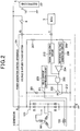
- FIG. 2 is a diagram showing a configuration of a power generation control apparatus for vehicles according to a modification of the embodiment.
- the power generation control apparatus 2A for vehicles shown in FIG. 2 differs from the power generation control apparatus 2 shown in FIG. 1 in that the resistor 209 is replaced with a signal equalizing circuit 210.
- the signal equalizing circuit 210 which corresponds to a signal equalizing section (signal equalizing means), equalizes the signal corresponding to the comparison result of the voltage comparator 204.
- the output signal of the voltage comparator 204 fluctuates due to engine speed, intermittent electrical loads which are constantly operated, or the like. However, since the output signal is equalized, the operation state of the generator 1 when the electrical loads are applied can be detected more accurately.
- the signal equalizing circuit 210 performs the equalization for a period of time longer than the control period of ignition of the vehicle.
- the period of time is, for example, more than 20 ms.
- the influence of ignition noise generated during idling can be eliminated, thereby allowing the operation state of the generator 1 (i.e. the state where the electrical loads are applied) to be more accurately detected and allowing the idling engine speed to be more stable.
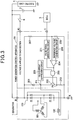
- FIG. 3 is a diagram showing a configuration of a power generation control apparatus for vehicles according to another modification of the embodiment.
- the power generation control apparatus 2B for vehicles shown in FIG. 3 differs from the power generation control apparatus 2 shown in FIG. 1 in that the resistor 209 is replaced with a pulse signal generating circuit 211.
- the pulse signal generating circuit 211 which corresponds to a pulse signal generating section (pulse signal generating means), generates a pulse signal corresponding to the comparison result of the voltage comparator 204.
- the generated pulse signal is transmitted to the ECU 5 via the C terminal.
- the signal transmitted from the C terminal is a pulse signal
- the signal can be transmitted and received between the power generation control apparatus 2B and the ECU 5 by using serial communication such as LIN (Local Interconnect Network) communication. Therefore, when comparing the above-described transmission with any direct transmission of voltage values, the above-described transmission improves reliability of the communication and facilitates sharing a signal line when other information is transmitted.
- serial communication such as LIN (Local Interconnect Network) communication. Therefore, when comparing the above-described transmission with any direct transmission of voltage values, the above-described transmission improves reliability of the communication and facilitates sharing a signal line when other information is transmitted.
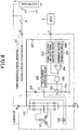
- FIG. 4 is a diagram showing a configuration of a power generation control apparatus for vehicles according to another modification of the embodiment.
- the power generation control apparatus 2C for vehicles shown in FIG. 4 differs from the power generation control apparatus 2 shown in FIG. 1 in that the resistor 209 is replaced with a signal equalizing and pulse signal generating circuit 212.
- the signal equalizing and pulse signal generating circuit 212 has both functions of the signal equalizing circuit 210 shown in FIG. 2 and the pulse signal generating circuit 211 shown in FIG. 3 .
- the signal equalizing and pulse signal generating circuit 212 equalizes the signal corresponding to the comparison result of the voltage comparator 204 and generates a pulse signal corresponding to the equalized signal.
- the generated pulse signal is transmitted to the ECU 5 via the C terminal.
- control is performed so that the output voltage of the generator 1 agrees with the regulation voltage.
- the voltage at the terminal of the battery 3 (the voltage at the positive-pole terminal) may be applied to the voltage comparator 204 via a predetermined sensing line. In consequence, control is performed so that the voltage at the terminal of the battery 3 agrees with the regulation voltage.
- the resistor 209 serving as a protective resistor may be removed according to the principle of operation.
- the resistor 209 may be replaced with a protective diode or another protective circuit.
- the voltage comparator 204 and the C terminal may be connected via a conversion circuit in which the level of the output voltage of the voltage comparator 204 is converted.
Landscapes
- Engineering & Computer Science (AREA)
- Power Engineering (AREA)
- Control Of Eletrric Generators (AREA)
Claims (11)
- Vorrichtung (2) zum Steuern einer Leistungserzeugung in Fahrzeugen, die eine Maschine beinhalten, der ein Generator (1) beigeordnet ist, der eine Feldwicklung (102) und eine Batterie (3) aufweist, aufweisend:einen Spannungsvergleichsabschnitt (207, 208, 204, 206), der entweder die Ausgangsspannung des Generators (1) oder die Klemmenspannung der Batterie (3) mit einer vorgegebenen Regelspannung vergleicht;einen Feldstromsteuerabschnitt (202), der den Feldstrom steuert, der durch die Feldwicklung (102) des Generators (1) strömt;einen Feldstromunterdrückungsabschnitt (203, 205, 213), der den Feldstromsteuerabschnitt (202) auf Basis eines Vergleichsergebnisses des Spannungsvergleichsabschnitts (207, 208, 204, 206), um den Feldstrom zu unterdrücken, und den Feldstrom graduell erhöht oder den Maximalwert des Feldstroms beschränkt; undein externer Ausgangsanschluss (C), bei dem es sich um einen Kommunikationsanschluss handelt, der mit einer externen Steuereinheit (5) verbunden ist, die sich außerhalb des Generators (1) und der Vorrichtung (2) befindet, der entweder ein erstes Signal, das von dem Spannungsvergleichsabschnitt (207, 208, 204, 206) ausgegeben und in den Feldstromunterdrückungsabschnitt (203, 205, 213) eingespeist wird, oder ein zweites Signal, das dem ersten Signal entspricht, überträgt, wobei das erste oder das zweite Signal, das erhalten wird, indem die Ausgangsspannung des Generators (1) mit der Regelspannung vor der Durchführung der Steuerung verglichen wird, an den externen Ausgangsanschluss (C) übertragen wird, ohne den Feldstromunterdrückungsabschnitt (203, 205, 213) zu durchlaufen, so dass die externe Steuereinheit (5) eine Steuerung der Maschinenleerlaufdrehzahl als Reaktion auf eine angelegte elektrische Last durchführen kann, um die Maschinenleerlaufdrehzahl zu stabilisieren,dadurch gekennzeichnet, dass
der Feldstromunterdrückungsabschnitt (203, 205, 213) eine Feldstromunterdrückungsschaltung (205) aufweist, die eine Spannung an einem Verbindungspunkt zwischen dem Feldstromsteuerabschnitt (202) und der Feldwicklung (102) erfasst, und
die Vorrichtung (2) ferner einen Signalentzerrungsabschnitt (210) aufweist, der das erste oder zweite Signal entzerrt, wobei der Signalentzerrungsabschnitt (210) eine Entzerrung für einen Zeitraum durchführt, der länger ist als ein Steuerzeitraum der Zündung des Fahrzeugs, so dass der Einfluss des Zündungsgeräusches, das während des Leerlaufs erzeugt wird, eliminiert werden kann, wodurch der Betriebszustand des Generators (1) genauer erfasst werden kann und die Maschinenleerlaufdrehzahl stabiler sein kann. - Vorrichtung nach Anspruch 1, ferner aufweisend einen Pulssignalerzeugungsabschnitt (211), der ein Pulssignal erzeugt, das dem ersten oder zweiten Signal entspricht,
wobei das Pulssignal über den externen Ausgangsanschluss (C) übertragen wird. - Vorrichtung nach Anspruch 1, wobei der Zeitraum länger als 20 ms ist.
- Vorrichtung nach Anspruch 1, ferner aufweisend einen Pulssignalerzeugungsabschnitt (211), der ein Pulssignal erzeugt, das dem entzerrten Signal entspricht, wobei das entzerrte Signal über einen externen Ausgangsanschluss (C) übertragen wird.
- Vorrichtung nach Anspruch 4, wobei der Signalentzerrungsabschnitt (210) eine Entzerrung für einen Zeitraum durchführt, der länger ist als ein Steuerzeitraum der Zündung des Fahrzeugs.
- Vorrichtung nach Anspruch 5, wobei der Zeitraum länger als 20 ms ist.
- Vorrichtung nach Anspruch 1, wobei der Feldstromunterdrückungsabschnitt (203, 205, 213) ein drittes Signal mit einem Tastverhältnis erzeugt, das erhalten wird, indem das Tastverhältnis der erfassten Spannung mit einer vorgegebenen Erhöhungsrate erhöht wird.
- Vorrichtung nach Anspruch 7, wobei der Feldstromunterdrückungsabschnitt (203, 205, 213) den Feldstromsteuerabschnitt (202) auf Basis des Vergleichsergebnisses und des dritten Signals ansteuert.
- Vorrichtung nach Anspruch 1, wobei der Feldstromunterdrückungsabschnitt (203, 205, 213) eine Spannung an einer Ausgangsseite des Feldstromsteuerabschnitts (202) erfasst.
- Vorrichtung nach Anspruch 9, wobei der Feldstromunterdrückungsabschnitt (203, 205, 213) ein viertes Signal erzeugt, das ein beschränktes Tastverhältnis aufweist, so dass die zu erfassende Spannung an der Ausgangsseite einen vorgegebenen Wert nicht überschreitet.
- Vorrichtung nach Anspruch 10, wobei der Feldstromunterdrückungsabschnitt (203, 205, 213) den Feldstromsteuerabschnitt (202) auf Basis des Vergleichsergebnisses und des vierten Signals ansteuert.
Applications Claiming Priority (1)
| Application Number | Priority Date | Filing Date | Title |
|---|---|---|---|
| JP2007281656A JP4488054B2 (ja) | 2007-10-30 | 2007-10-30 | 車両用発電制御装置 |
Publications (3)
| Publication Number | Publication Date |
|---|---|
| EP2056443A2 EP2056443A2 (de) | 2009-05-06 |
| EP2056443A3 EP2056443A3 (de) | 2010-03-10 |
| EP2056443B1 true EP2056443B1 (de) | 2019-02-20 |
Family
ID=40383823
Family Applications (1)
| Application Number | Title | Priority Date | Filing Date |
|---|---|---|---|
| EP08017314.9A Ceased EP2056443B1 (de) | 2007-10-30 | 2008-10-01 | Vorrichtung zur Steuerung der Stromerzeugung in Fahrzeugen |
Country Status (2)
| Country | Link |
|---|---|
| EP (1) | EP2056443B1 (de) |
| JP (1) | JP4488054B2 (de) |
Families Citing this family (1)
| Publication number | Priority date | Publication date | Assignee | Title |
|---|---|---|---|---|
| JP5452654B2 (ja) * | 2012-04-11 | 2014-03-26 | 三菱電機株式会社 | 車両用交流発電機の制御装置 |
Family Cites Families (8)
| Publication number | Priority date | Publication date | Assignee | Title |
|---|---|---|---|---|
| JPH0619359A (ja) | 1992-06-30 | 1994-01-28 | Canon Inc | 定着装置 |
| JP3531771B2 (ja) * | 1994-12-28 | 2004-05-31 | 株式会社デンソー | 車両用充電装置 |
| JP3840675B2 (ja) | 1995-09-12 | 2006-11-01 | 株式会社デンソー | 車両用発電機の制御装置 |
| JP4547846B2 (ja) * | 2001-09-28 | 2010-09-22 | 株式会社デンソー | 車両用発電制御装置 |
| JP3997984B2 (ja) * | 2003-12-08 | 2007-10-24 | 株式会社デンソー | 車両用発電制御装置 |
| JP4524663B2 (ja) * | 2005-11-02 | 2010-08-18 | 株式会社デンソー | 車両用電圧制御装置 |
| JP4682901B2 (ja) * | 2006-04-04 | 2011-05-11 | 株式会社デンソー | 発電制御システム |
| JP2007281656A (ja) | 2006-04-04 | 2007-10-25 | Sharp Corp | 映像表示装置 |
-
2007
- 2007-10-30 JP JP2007281656A patent/JP4488054B2/ja not_active Expired - Fee Related
-
2008
- 2008-10-01 EP EP08017314.9A patent/EP2056443B1/de not_active Ceased
Non-Patent Citations (1)
| Title |
|---|
| None * |
Also Published As
| Publication number | Publication date |
|---|---|
| EP2056443A3 (de) | 2010-03-10 |
| JP4488054B2 (ja) | 2010-06-23 |
| JP2009112109A (ja) | 2009-05-21 |
| EP2056443A2 (de) | 2009-05-06 |
Similar Documents
| Publication | Publication Date | Title |
|---|---|---|
| US7285937B2 (en) | Electric generation control apparatus for vehicle alternator | |
| US7812469B2 (en) | Battery current detection apparatus incorporated in system which regulates vehicle engine speed and electric generator output voltage during engine idling | |
| US7683588B2 (en) | Device for controlling power generated in vehicle | |
| JP4182957B2 (ja) | 発電制御装置 | |
| JP4826565B2 (ja) | 充電システムおよび車両用発電制御装置 | |
| US20090102425A1 (en) | Vehicle-use power supply management apparatus | |
| US7423351B2 (en) | Vehicle-generator control device | |
| CN103580589A (zh) | 用于机动车辆的电旋转机器 | |
| US20040135374A1 (en) | Vehicle generator control system | |
| CN101179202A (zh) | 向车载计算机传送电压调节器开关信息的系统和方法 | |
| CN111479721A (zh) | 控制机动车辆的车载网络中的直流转换器的方法 | |
| JP4502022B2 (ja) | 車両用発電制御装置 | |
| US9397601B2 (en) | Power generation control unit determining maximum excitation current of power generator mounted on vehicle | |
| JP4682901B2 (ja) | 発電制御システム | |
| JP5115539B2 (ja) | 車両用発電制御装置および車両用発電機制御システム | |
| KR101786141B1 (ko) | 자동차 교류 발전기의 조절을 제어하는 방법 및 대응 디바이스 | |
| CN104969439B (zh) | 用于运行机动车的车载电网的供电单元的方法 | |
| EP2056443B1 (de) | Vorrichtung zur Steuerung der Stromerzeugung in Fahrzeugen | |
| US8138729B2 (en) | Generation control apparatus for vehicles that controls current supply to a field winding of a generator to control output voltage of the generator | |
| US7723963B2 (en) | Target regulation voltage setting apparatus | |
| EP1401081A2 (de) | Intelligentes Spannungsregelsystem in einem Kraftfahrzeug | |
| WO2019052481A1 (en) | ALTERNATOR SYSTEM | |
| JP3405029B2 (ja) | 車両用発電機の電圧制御装置 | |
| US20230318348A1 (en) | Vehicle-power-generator control apparatus | |
| JP4169007B2 (ja) | 車両用発電制御装置 |
Legal Events
| Date | Code | Title | Description |
|---|---|---|---|
| PUAI | Public reference made under article 153(3) epc to a published international application that has entered the european phase |
Free format text: ORIGINAL CODE: 0009012 |
|
| AK | Designated contracting states |
Kind code of ref document: A2 Designated state(s): AT BE BG CH CY CZ DE DK EE ES FI FR GB GR HR HU IE IS IT LI LT LU LV MC MT NL NO PL PT RO SE SI SK TR |
|
| AX | Request for extension of the european patent |
Extension state: AL BA MK RS |
|
| PUAL | Search report despatched |
Free format text: ORIGINAL CODE: 0009013 |
|
| AK | Designated contracting states |
Kind code of ref document: A3 Designated state(s): AT BE BG CH CY CZ DE DK EE ES FI FR GB GR HR HU IE IS IT LI LT LU LV MC MT NL NO PL PT RO SE SI SK TR |
|
| AX | Request for extension of the european patent |
Extension state: AL BA MK RS |
|
| RIC1 | Information provided on ipc code assigned before grant |
Ipc: H02P 9/30 20060101ALI20100203BHEP Ipc: H02J 7/24 20060101ALI20100203BHEP Ipc: H02P 9/02 20060101ALI20100203BHEP Ipc: H02P 9/48 20060101AFI20100203BHEP |
|
| 17P | Request for examination filed |
Effective date: 20100910 |
|
| AKX | Designation fees paid |
Designated state(s): DE FR |
|
| 17Q | First examination report despatched |
Effective date: 20120412 |
|
| STAA | Information on the status of an ep patent application or granted ep patent |
Free format text: STATUS: EXAMINATION IS IN PROGRESS |
|
| GRAP | Despatch of communication of intention to grant a patent |
Free format text: ORIGINAL CODE: EPIDOSNIGR1 |
|
| STAA | Information on the status of an ep patent application or granted ep patent |
Free format text: STATUS: GRANT OF PATENT IS INTENDED |
|
| INTG | Intention to grant announced |
Effective date: 20180820 |
|
| GRAS | Grant fee paid |
Free format text: ORIGINAL CODE: EPIDOSNIGR3 |
|
| GRAA | (expected) grant |
Free format text: ORIGINAL CODE: 0009210 |
|
| STAA | Information on the status of an ep patent application or granted ep patent |
Free format text: STATUS: THE PATENT HAS BEEN GRANTED |
|
| RIN1 | Information on inventor provided before grant (corrected) |
Inventor name: WATANABE, YASUYUKI |
|
| AK | Designated contracting states |
Kind code of ref document: B1 Designated state(s): DE FR |
|
| REG | Reference to a national code |
Ref country code: DE Ref legal event code: R096 Ref document number: 602008059015 Country of ref document: DE |
|
| REG | Reference to a national code |
Ref country code: DE Ref legal event code: R097 Ref document number: 602008059015 Country of ref document: DE |
|
| REG | Reference to a national code |
Ref country code: DE Ref legal event code: R084 Ref document number: 602008059015 Country of ref document: DE |
|
| PLBE | No opposition filed within time limit |
Free format text: ORIGINAL CODE: 0009261 |
|
| STAA | Information on the status of an ep patent application or granted ep patent |
Free format text: STATUS: NO OPPOSITION FILED WITHIN TIME LIMIT |
|
| 26N | No opposition filed |
Effective date: 20191121 |
|
| PGFP | Annual fee paid to national office [announced via postgrant information from national office to epo] |
Ref country code: DE Payment date: 20191021 Year of fee payment: 12 |
|
| PGFP | Annual fee paid to national office [announced via postgrant information from national office to epo] |
Ref country code: FR Payment date: 20191028 Year of fee payment: 12 |
|
| REG | Reference to a national code |
Ref country code: DE Ref legal event code: R119 Ref document number: 602008059015 Country of ref document: DE |
|
| PG25 | Lapsed in a contracting state [announced via postgrant information from national office to epo] |
Ref country code: DE Free format text: LAPSE BECAUSE OF NON-PAYMENT OF DUE FEES Effective date: 20210501 Ref country code: FR Free format text: LAPSE BECAUSE OF NON-PAYMENT OF DUE FEES Effective date: 20201031 |