EP2056017A1 - Light refracting plate - Google Patents
Light refracting plate Download PDFInfo
- Publication number
- EP2056017A1 EP2056017A1 EP08018903A EP08018903A EP2056017A1 EP 2056017 A1 EP2056017 A1 EP 2056017A1 EP 08018903 A EP08018903 A EP 08018903A EP 08018903 A EP08018903 A EP 08018903A EP 2056017 A1 EP2056017 A1 EP 2056017A1
- Authority
- EP
- European Patent Office
- Prior art keywords
- light
- gratings
- convex lens
- distribution board
- saw toothed
- Prior art date
- Legal status (The legal status is an assumption and is not a legal conclusion. Google has not performed a legal analysis and makes no representation as to the accuracy of the status listed.)
- Withdrawn
Links
- 238000009826 distribution Methods 0.000 claims abstract description 129
- 230000002093 peripheral effect Effects 0.000 claims 2
- 230000001678 irradiating effect Effects 0.000 description 33
- 230000000694 effects Effects 0.000 description 19
- 238000005286 illumination Methods 0.000 description 14
- 238000009827 uniform distribution Methods 0.000 description 12
- 230000002250 progressing effect Effects 0.000 description 9
- 238000000034 method Methods 0.000 description 3
- 238000005452 bending Methods 0.000 description 2
- 230000007547 defect Effects 0.000 description 2
- 208000002173 dizziness Diseases 0.000 description 2
- 210000000887 face Anatomy 0.000 description 2
- 230000003631 expected effect Effects 0.000 description 1
- 230000003287 optical effect Effects 0.000 description 1
Images


Classifications
-
- G—PHYSICS
- G02—OPTICS
- G02B—OPTICAL ELEMENTS, SYSTEMS OR APPARATUS
- G02B5/00—Optical elements other than lenses
- G02B5/18—Diffraction gratings
- G02B5/1876—Diffractive Fresnel lenses; Zone plates; Kinoforms
- G02B5/189—Structurally combined with optical elements not having diffractive power
-
- G—PHYSICS
- G02—OPTICS
- G02B—OPTICAL ELEMENTS, SYSTEMS OR APPARATUS
- G02B3/00—Simple or compound lenses
- G02B3/02—Simple or compound lenses with non-spherical faces
- G02B3/08—Simple or compound lenses with non-spherical faces with discontinuous faces, e.g. Fresnel lens
-
- G—PHYSICS
- G02—OPTICS
- G02B—OPTICAL ELEMENTS, SYSTEMS OR APPARATUS
- G02B27/00—Optical systems or apparatus not provided for by any of the groups G02B1/00 - G02B26/00, G02B30/00
- G02B27/09—Beam shaping, e.g. changing the cross-sectional area, not otherwise provided for
- G02B27/0938—Using specific optical elements
- G02B27/095—Refractive optical elements
-
- G—PHYSICS
- G02—OPTICS
- G02B—OPTICAL ELEMENTS, SYSTEMS OR APPARATUS
- G02B3/00—Simple or compound lenses
-
- G—PHYSICS
- G02—OPTICS
- G02B—OPTICAL ELEMENTS, SYSTEMS OR APPARATUS
- G02B5/00—Optical elements other than lenses
- G02B5/02—Diffusing elements; Afocal elements
Definitions
- This present invention relates to a light distribution board, and especially to a light distribution board that is designed based on the principles of optical reflection and refraction, and is applicable to various illumination lamp sets, each lamp set can thus illuminate a district with uniform brightness and tender light beams under the condition of minimum lose of brightness to be not dazzling; the light distribution board is applicable to a place such as a house, an office, a factory or a road requiring illumination, and can achieve an effect of saving energy as well as avoiding the phenomenon of dizzy irradiation.
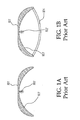
- Illuminating lamp sets generally are divided into two kinds including indoor and outdoor lamp sets; indoor lamp sets mainly are of a half covering type, each being installed with a half covering type obscured cover 101 above a light source 102 (referring to Fig. 1A ) having on an inner side thereof a reflective surface 103. These lamp sets normally are treated by fogging process on the surface of the light source to avoid irradiating of light to eyes to result a phenomenon of making them feel dazzling and dizzy.
- the outdoor lamp sets are fully covering type covers (referring to Figs. 1B ) in considering the factor of environment, it is mounted therebeneath with a transparent hood 104, the hood 104 is also treated by fogging process to avoid the phenomenon of dazzling of eyes during looking at the light source directly.
- the aforesaid two types have a common defect of losing much brightness by treatment by fogging process, these kinds of conventional lamp sets generally have the phenomenon of Gauss distribution that brightness of lamp sets are concentrated at an area exactly below each lamp.
- the present invention provided a light distribution board having on a rectangular transparent board of it a plurality of saw toothed light gratings which each is composed of a convex lens surface and a bevel plane lens surface, these saw toothed light gratings are arranged at two lateral sides of a central line of the transparent board to form mirror images one side to the other side, the bevel plane lens surfaces are arranged to face respectively to the two lateral sides of the transparent board, while the convex lens surfaces are arranged to face to the central line; the top surface is a light receiving surface of the lamp set.
- the bottom surface of the transparent board is formed thereon a plurality of convex-lens strip like light gratings, and the bottom surface is a light outputting surface of the lamp set.
- the light distribution board provided in the present invention can have a round transparent board, can be formed on a top surface of the transparent board a plurality of saw toothed light gratings, each light grating is composed of a convex lens surface and a bevel plane lens surface, these saw toothed light gratings are arranged at two lateral sides of a central line of the transparent board to form mirror images one side to the other side, the bevel plane lens surfaces are arranged to face respectively to the periphery of the transparent board, while the convex lens surfaces are arranged to face to the central line; the top surface is a light receiving surface of the lamp.
- the bottom surface of the transparent board is formed thereon a plurality of convex-lens annular light gratings, and the bottom surface is an illuminating surface of the lamp.
- the radius of the arched periphery and inclination angle of each convex lens surface of one of the saw toothed light gratings are changed in pursuance of the angles of refraction of the incident light beams through the convex lens surface. While size of every bevel plane lens surface and the inclination angle between each bevel plane lens surface and the horizontal line of each saw toothed light grating are changed in pursuance of the angles of refraction of the incident light beams through the bevel plane lens surface.
- the radii of the convex lens surfaces and the interspace between every two of the convex-lens strip like light gratings or the convex-lens annular light gratings are also changed in pursuance of the angles of refraction of the incident light beams through the convex lens surface.
- the light distribution board provided in the present invention can be further improved, namely, the middle areas on the top surface or the bottom surface of the transparent board where it is brightest under irradiation of a light source can be formed a plurality of convex-lens strip like or convex-lens annular light gratings.
- light beams can be uniformly distributed and can avoid the phenomenon of Gauss distribution that makes the area below the lamp especially bright, and can avoid the phenomenon of dazzling of eyes during looking at the light emitting member in the lamp, and the light beams become more tender under the condition that lose of brightness is minimum.
- the present invention relates to a light distribution board, in which a transparent board is used to form the light distribution board as an illuminating cover for a lamp.
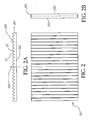
- a rectangular transparent board 201 has a plane surface 202, and has another surface being provided thereon with a plurality of strip-like saw toothed light gratings 203, each saw tooth of the strip-like saw toothed light gratings is composed of a convex lens surface S1 and a bevel plane lens surface S2, the strip-like saw toothed light gratings are arranged at two lateral sides of a central line 204 of the transparent board 201 to form mirror images one side to the other side, the convex lens surfaces S1 are arranged to face to the central line 204 of the transparent board 201, while the bevel plane lens surfaces S2 are arranged to face respectively to the two lateral sides of the transparent board 201.
- FIG. 3 showing an enlarged schematic view of a center area of a light distribution board 301 which has a plane bottom surface 302 and a top surface forming thereon a plurality of strip-like saw toothed light gratings 303.
- a light beam 306 When a light beam 306 enters a convex lens surface 311 of one of the saw toothed light gratings 303 and creates a first time refraction, the light beam 306 is transmitted to the plane bottom surface 302 to create a second time refraction and enters an area to be illuminated.
- the angles of light beams refraction are determined respectively by the radii and tilting angles of the arched periphery of the convex lens surfaces 310, 311; the larger the tilting angles of the arched peripheries are, the larger the refraction angles of the light beams irradiating out of the plane below the light distribution board 301 will be, namely, the larger the range of width that the light beams irradiating toward the lateral sides will be.
- a light beam 308 enters a bevel plane lens surface 312 of one of the saw toothed light gratings 303 and creates a first time refraction
- the light beam 308 is transmitted to the plane bottom surface 302 to create a second time refraction and enters an area to be illuminated.
- a light beam 309 enters a bevel plane lens surface 313 of one of the saw toothed light gratings 03 and creates a first time refraction
- the light beam 309 is transmitted to the plane bottom surface 302 to create a second time refraction and also enters an area to be illuminated.
- the light beam refraction angles are determined by the intersection angles respectively between the bevel plane lens surfaces 312, 313 and the horizontal line; the larger the intersection angles between the bevel plane lens surfaces 312, 313 and the horizontal line are, the larger the refraction angles of the light beams irradiating out of the plane below the light distribution board 301 will be, namely, the larger the range of width that the light beams irradiating toward the lateral sides will be.
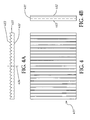
- a rectangular transparent board 401 is formed on a surface of it a plurality of strip-like saw toothed light gratings 403 as shown in Fig. 2 , and a plurality of strip-like convex lens light gratings 402 are formed on another surface of it; the strip-like saw toothed light gratings 403 are arranged at two lateral sides of a central line 404 of the transparent board 401 to form mirror images one side to the other side.
- FIG. 5 showing an enlarged schematic view of a center area of a light distribution board 501 which has a plane bottom surface provided thereon with a plurality of strip-like convex lens light gratings 513, 516 etc., and a top surface forming thereon a plurality of strip-like saw toothed light gratings 502, the sole difference between this drawing and Fig. 3 is that the bottom surface of the light distribution board 501 has thereon the strip-like convex lens light gratings 513, 516 etc.
- a light beam 505, 508, 511, 514 pass through their correspondent convex lens surfaces 506, 509 of the strip-like saw toothed light gratings 502 or their correspondent bevel plane surfaces 512, 515 and create a first time refraction
- the light beams are transmitted to the strip-like convex lens light gratings 513, 516 and two plane surfaces 507, 510 on the bottom surface to create a second time refraction and enters an area to be illuminated with different angles of refraction.
- the radii of the convex lenses of these strip-like convex lens light gratings 513, 516 etc. directly influence generation of the angles of the second time refraction of the light beams.
- This has a certain regulation that is, the larger the radii of the convex lenses of these strip-like convex lens light gratings are, the smaller the incidence angles of the light beams will be; correspondingly, the smaller the angle of the light beams irradiating out of the light distribution board 501 is, the smaller the range of width of the area to be illuminated will be.
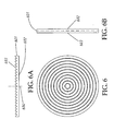
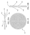
- a round transparent board 601 has a plane bottom surface 602, and has a top surface being provided thereon with a plurality of annular saw toothed light gratings 603; the combination structure of the annular saw toothed light gratings 603 is similar to that of the strip-like saw toothed light gratings 203 as shown in Fig.
- annular saw toothed light gratings 603 are arranged in an annular form taking a round center 604 of the transparent board 601 as their center, the principle of design and the effect of generating different illumination of the arched peripheries of the convex lenses and of the bevel plane lens surfaces are same as those stated for Fig. 3 .
- a round transparent board 701 is formed on a top surface of it a plurality of annular saw toothed light gratings 703 as shown in Fig. 6 , the annular saw toothed light gratings 703 are arranged in an annular form taking a round center 704 of the transparent board 701 as their center; and a plurality of annular convex lens light gratings 702 are formed on another (bottom) surface of it; the principle of design and the effect of generating different illumination of the radius of the convex lens is same as that stated for Fig. 5 .
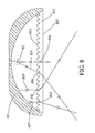
- a light distribution board 801 is movably mounted at an area to be illuminated under a main body 105 of the lamp set, a plane bottom surface 802 of the light distribution board 801 faces to a light source 102 as a light receiving surface, another (top) surface is formed thereon a plurality of saw toothed light gratings 803 as a light outputting surface facing to the light source 102; the saw toothed light gratings 803 are arranged at two lateral sides of a central line of the transparent board 801 to form mirror images one side to the other side, the convex lens surfaces are arranged to face to the central line, while the bevel plane lens surfaces are arranged to face respectively to the two lateral sides of the transparent board; the center of the transparent board 801 is aligned with the point right under the light source 102.
- a light beam 805 enters a convex lens surface 806 of one of the saw toothed light gratings 803 and creates a first time refraction
- the light beam 805 is transmitted to the plane bottom surface 802 to create a second time refraction going downwardly and leftwards of the lamp set and enters an area to be illuminated.
- a light beam 807 enters a convex lens surface 808 of one of the saw toothed light gratings 803 and creates a first time refraction
- the light beam 807 is transmitted to the plane bottom surface 802 to create a second time refraction going downwardly and leftwards of the lamp set and enters an area to be illuminated.
- a light beam 809 enters a bevel plane lens surface 810 of one of the saw toothed light gratings 803 of the light distribution board 801 and creates a first time refraction
- the light beam 809 is transmitted to the plane bottom surface 802 to create a second time refraction going downwardly and rightwards of the lamp set and also enters an area to be illuminated.
- the light distribution board 801 surely can control illumination of most of the light beams in the lamp set onto a predetermined area to be illuminated, and can get an effect of saving energy with uniform distribution of brightness, and tender light beams at the district to be illuminated can be obtained.
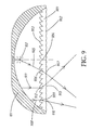
- a light distribution board 901 is movably mounted at an area to be illuminated under a main body 105 of the lamp set, a plane bottom surface of the light distribution board 901 is formed thereon a plurality of convex lens light gratings 902 as a light outputting surface facing to the area to be illuminated; another (top) surface is formed thereon a plurality of saw toothed light gratings 903 facing to a light source 102 as a light receiving surface; the saw toothed light gratings 903 are arranged at two lateral sides of a central line of the transparent board 901 to form mirror images one side to the other side, the convex lens surfaces are arranged to face to the central line, while the bevel plane lens surfaces are arranged to face respectively to the two lateral sides of the transparent board; the center of the transparent board 901 is aligned with the point right under the light source 102.
- a light beam 905 enters a convex lens surface 906 of one of the saw toothed light gratings 903 of the light distribution board 901 and creates a first time refraction
- the light beam 905 is transmitted to a convex lens 907 beneath the light distribution board 901 to create a second time refraction going downwardly and leftwards of the lamp set and enters an area to be illuminated.
- a light beam 911 enters a bevel plane lens surface 912 of one of the saw toothed light gratings 903 of the light distribution board 901 and creates a first time refraction
- the light beam 911 is transmitted to the plane bottom surface 913 to create a second time refraction going downwardly and rightwards of the lamp set and also enters an area to be illuminated.
- the light distribution board 901 surely can control illumination of most of the light beams in the lamp set onto a predetermined area to be illuminated, and can get an effect of saving energy with uniform distribution of brightness, and tender light beams at the district to be illuminated can be obtained.
- the light distribution board provided in the present invention can be further improved, namely, the middle areas on the top surface or the bottom surface of the transparent board where it is brightest under irradiation of a light source can be formed a plurality of strip-like convex lens light gratings.
- light beams can be uniformly distributed and can avoid the phenomenon of Gauss distribution that makes the area below the lamp especially bright, and can avoid the phenomenon of dazzling of eyes during looking at the light emitting member in the lamp, and the light beams become more tender under the condition that lose of brightness is minimum.
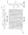
- a rectangular transparent board 1201 has a plane surface 1202, and has another surface being provided thereon with a plurality of strip-like convex lens light gratings and a plurality of strip-like saw toothed light gratings 1203 at the two lateral sides of the former strip-like convex lens light gratings, each saw tooth of the strip-like saw toothed light gratings is composed of a convex lens surface S1 and a bevel plane lens surface S2, the strip-like saw toothed light gratings are arranged at two lateral sides of a central line 1204 of the transparent board 1201 to form mirror images one side to the other side, the convex lens surfaces S1 are arranged to face to the central line 1204 of the transparent board 1201, while the bevel plane lens surfaces S2 are arranged to face respectively to the two lateral sides of the transparent
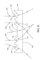
- FIG. 11 showing an enlarged schematic view of a center area of an improved light distribution board 1301 which has a plane bottom surface 1302 and a top surface forming thereon a plurality of strip-like convex lens light gratings 1304 and strip-like saw toothed light gratings 1303.
- a light beam 1314 When a light beam 1314 enters a convex lens 1305 of one of the convex lens light gratings 1304 and creates a first time refraction, the light beam 1314 is transmitted to the plane bottom surface 1302 to create a second time refraction and enters an area to be illuminated.
- the angle of the light beam 1314 refracted outwards is determined by the radius of the arched convex lens surface; the larger the radius of the arched convex lens surface is (i.e., the smaller the bending curvature of the arched convex lens surface is), the smaller the angles of the refracted light beams irradiating out of the plane below the light distribution board 1301 is, namely, the smaller the range of width that the light beams irradiating toward the lateral sides will be.
- a light beam 1306 enters a convex lens 1311 of one of the saw toothed light gratings 1303 and creates a first time refraction
- the light beam 1306 is transmitted to the plane bottom surface 1302 to create a second time refraction and enters an area to be illuminated.
- the light beam 1307 after entering a convex lens 1310 of one of the saw toothed light gratings 1303 creates a first time refraction, the light beam 1307 is transmitted to the plane bottom surface 1302 to create a second time refraction and enters an area to be illuminated.
- the angles of light beams refracted outwards are determined by the radii and tilting angles of the arched peripheries of the convex lens surfaces 1310, 1311; the larger the tilting angles of the arched peripheries are, the larger the refraction angles of the light beams irradiating out of the plane below the light distribution board 1301 will be, namely, the larger the range of width that the light beams irradiating toward the lateral sides will be.
- a light beam 1308 enters a bevel plane lens surface 1312 of one of the saw toothed light gratings 1303 and creates a first time refraction
- the light beam 1308 is transmitted to the plane bottom surface 1302 to create a second time refraction and enters an area to be illuminated.
- a light beam 1309 enters a bevel plane lens surface 1313 of one of the saw toothed light gratings 1303 and creates a first time refraction
- the light beam 1309 is transmitted to the plane bottom surface 1302 to create a second time refraction and also enters an area to be illuminated.
- the light beam refraction angles are determined by the intersection angles respectively between the bevel plane lens surfaces 1312, 1313 and the horizontal line; the larger the intersection angles between the bevel plane lens surfaces 1312, 1313 and the horizontal line are, the larger the refraction angles of the light beams irradiating out of the plane below the light distribution board 1301 will be, namely, the larger the range of width that the light beams irradiating toward the lateral sides will be.
- a rectangular transparent board 1401 is formed on a surface of it a plurality of strip-like convex lens light gratings 1405 and a plurality of strip-like saw toothed light gratings 1403 as shown in Fig. 10 , and a plurality of strip-like convex lens light gratings 1402 are formed on partial area of a plane surface 1406; the strip-like saw toothed light gratings 1403 are arranged at two lateral sides of a central line 1404 of the transparent board 1401 to form mirror images one side to the other side.
- a light distribution board 1501 which has a plane bottom surface provided on partial area thereof with a plurality of strip-like convex lens light gratings 1513, 1516 etc., and a top surface forming thereon a plurality of strip-like saw toothed light gratings 1502 and a plurality of strip-like convex lens light gratings 1503, the sole difference between this drawing and Fig. 3 is that the bottom surface of the light distribution board 1501 has thereon the strip-like convex lens light gratings 1513, 1516 etc. and some plane surfaces 1507, 1510.
- the light beam 1517 near the center passes through a strip-like convex lens light grating 1518 and a strip-like convex lens light grating 1519 to create a second time refraction and enters an area to be illuminated, in this way, the light beams in the middle of the light distribution board 1501 can be uniformly distributed and can avoid the phenomenon of making the area right below the lamp especially bright.
- the radii of the convex lenses of the lower strip-like convex lens light gratings 1519 directly influence generation of the angles of the second time refraction of the light beams.
- a round transparent board 1601 has a plane bottom surface 1602, and has a top surface being provided thereon with a plurality of annular convex lens light gratings 1605 and a plurality of annular saw toothed light gratings 1603; the combination structure of the annular convex lens light gratings 1605 and the annular saw toothed light gratings 1603 is similar to that of the annular convex lens light gratings 1205 and the strip-like saw toothed light gratings 1203 as shown in Fig.
- annular saw toothed light gratings 1603 and the annular convex lens light gratings 1605 are arranged in an annular form taking a round center 1604 of the transparent board 1601 as their center, the principle of design and the effect of generating different illumination of the arched peripheries of the convex lenses and of the bevel plane lens surfaces are same as those stated for Fig. 11 .
- a round transparent board 1701 is formed on a top surface of it a plurality of annular convex lens light gratings 1705 and a plurality of annular saw toothed light gratings 1703 as shown in Fig.
- the annular convex lens light gratings 1705 and annular saw toothed light gratings 1703 are arranged in an annular form taking a round center 1704 of the transparent board 1701 as their center; and a plurality of annular convex lens light gratings 1702 and some planes 1706 are formed on another (bottom) surface of it; the principle of design and the effect of generating different illumination of the radii of the convex lenses are same as that stated for Fig. 13 .
- a light distribution board 1801 is movably mounted at an area to be illuminated under a main body 105 of the lamp set, a plane bottom surface 1802 of the light distribution board 1801 faces to an area to be illuminated as a light receiving surface, another (top) surface is formed thereon a plurality of convex lens light gratings 1804 and a plurality of saw toothed light gratings 1803 as a light outputting surface facing to the light source 102; the center of the light distribution board 1801 is aligned with the light source 102 from below.
- a light beam 1805 enters a convex lens surface 1806 of one of the saw toothed light gratings 1803 of the improved light distribution board and creates a first time refraction
- the light beam 1805 is transmitted to the plane bottom surface 1802 to create a second time refraction going downwardly and leftwards of the lamp set and enters an area to be illuminated.
- a light beam 1807 enters a convex lens surface 1808 of one of the saw toothed light gratings 1803 and creates a first time refraction
- the light beam 1807 is transmitted to the plane bottom surface 1802 to create a second time refraction going downwardly and leftwards of the lamp set and enters an area to be illuminated.
- the improved light distribution board 1801 When a light beam 1809 enters a bevel plane lens surface 1810 of one of the saw toothed light gratings 1803 of the improved light distribution board 1801 and creates a first time refraction, the light beam 1809 is transmitted to the plane bottom surface 1802 to create a second time refraction going downwardly and rightwards of the lamp set and also enters an area to be illuminated.
- a light beam 1812 enters a convex lens surface 1811 of one of the convex lens light gratings 1804 and creates a first time refraction
- the light beam 1812 is transmitted to the plane bottom surface 1802 to create a second time refraction going downwardly to a central area below the lamp set and enters an area to be illuminated.
- the improved light distribution board 1801 surely can control illumination of most of the light beams in the lamp set onto a predetermined area to be illuminated, and can get an effect of saving energy with uniform distribution of brightness, and tender light beams at the district to be
- the improved light distribution board 1901 is movably mounted at an area to be illuminated under a main body 105 of the lamp set, a plane bottom surface of the light distribution board 1901 is formed thereon partially a plurality of convex lenses 1904 and partially some planes 1902, 1913 and is a light outputting surface facing to the area to be illuminated; another (top) surface is formed on its center area a plurality of convex lens light gratings 1917 of which two lateral sides are formed a plurality of saw toothed light gratings 1903 facing to a light source 102 as a light receiving surface; the center of the transparent board 1901 is aligned with the point right under the light source 102.
- a light beam 1905 enters a convex lens surface 1906 of one of the saw toothed light gratings 1903 of the improved light distribution board 1901 and creates a first time refraction
- the light beam 1905 is transmitted to a convex lens 1907 beneath the improved light distribution board 1901 to create a second time refraction going downwardly and leftwards of the lamp set and enters an area to be illuminated.
- a light beam 1908 enters a convex lens surface 1909 of one of the saw toothed light gratings 1903 of the improved light distribution board 1901 and creates a first time refraction
- the light beam 1908 is transmitted to a convex lens 1910 beneath the improved light distribution board 1901 to create a second time refraction going downwardly and leftwards of the lamp set and enters an area to be illuminated.
- a light beam 1911 enters a bevel plane lens surface 1912 of one of the saw toothed light gratings 1903 of the light improved distribution board 1901 and creates a first time refraction
- the light beam 1911 is transmitted to the plane bottom surface 1913 to create a second time refraction going downwardly and rightwards of the lamp set and also enters an area to be illuminated.
- a light beam 1914 enters a convex lens surface 1915 of one of the convex lens light gratings 1917 of the improved light distribution board 1901 and creates a first time refraction
- the light beam 1914 is transmitted to a convex lens 1916 beneath the improved light distribution board 1901 to create a second time refraction going right downwardly of the lamp set and enters an area to be illuminated.
- the light distribution board 1901 surely can control illumination of most of the light beams in the lamp set onto a predetermined area to be illuminated, and can get an effect of saving energy with uniform distribution of brightness, and tender light beams at the district to be illuminated can be
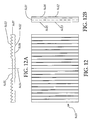
- Fig. 18 showing an enlarged schematic view of a center area of a light distribution board 2001 which has a plane bottom surface 2002, and a top surface forming thereon a plurality of strip-like saw toothed light gratings 2003.
- the facing orientation of the strip-like saw toothed light gratings 2003 of the light distribution board 2001 is exactly contrary to that of Fig. 3 , the saw toothed light gratings 2003 saw toothed light gratings 2003 are arranged at two lateral sides of a central line 2014 of the light distribution board 2001 to form mirror images one side to other side, of which bevel plane lens surfaces are arranged to face to a central line, the convex lens surfaces are arranged to face respectively to two lateral sides of the light distribution board 2001.
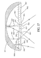
- a light beam 2006 When a light beam 2006 enters a convex lens surface 2013 of one of the saw toothed light gratings 2003 and creates a first time refraction, the light beam 2006 is transmitted to the plane bottom surface 2002 to create a second time refraction and enters an area to be illuminated; when a light beam 2007 enters a convex lens surface 2012 of one of the saw toothed light gratings 2003 and creates a first time refraction, the light beam 2007 is transmitted to the plane bottom surface 2002 to create a second time refraction and enters the area to be illuminated.
- the light beams 2006 and 2007 We can see from the light beams 2006 and 2007 that, the light beams enter correspondent convex lens surfaces all irradiate downward to the center of the light distribution board 2001 after twice refraction, the light beam refraction angles are determined by the radii and the tilting angles of the arched periphery of the convex lens surfaces, the larger the tilting angles of the arched periphery are, the larger the refraction angles of the light beams irradiating out of the plane below the light distribution board 2001 will be, namely, the larger the range of width that the light beams irradiating toward the lateral sides will be.
- a light beam 2008 enters a bevel plane lens surface 2010 of one of the saw toothed light gratings 2003 and creates a first time refraction
- the light beam 2008 is transmitted to the plane bottom surface 2002 to create a second time refraction and enters an area to be illuminated.
- a light beam 2009 enters a bevel plane lens surface 2011 of one of the saw toothed light gratings 2003 and creates a first time refraction
- the light beam 2009 is transmitted to the plane bottom surface 2002 to create a second time refraction and also enters an area to be illuminated.
- the light beams 2008 and 2009 that, the light beams enter correspondent bevel plane lens surfaces all irradiate downward to the two lateral sides of the light distribution board 2001 after twice refraction, the angles of light beams refraction are determined respectively by the intersection angles respectively between the bevel plane lens surfaces 2010, 2011 and the horizontal line; the larger the intersection angles between the bevel plane lens surfaces 2010, 2011 and the horizontal line are, the larger the refraction angles of the light beams irradiating out of the plane below the light distribution board 2001 will be, namely, the larger the range of width that the light beams irradiating toward the lateral sides will be.
- a transparent board 2101 has a plane bottom surface 2102, another (top) surface of it is formed thereon and in its central area a plurality of non-concentric annular saw toothed light gratings 2112 and partially a plurality of annular saw toothed light gratings 2103, 2104, 2105, 2106, 2107, 2108, 2109, 2110 and 2111.
- the structure arranged of the annular saw toothed light gratings 2103-2111 on the transparent board 2101 is same as the structure arranged from the saw toothed light gratings 303 shown in Fig. 3 , the principle of design and the effect of generating different illumination of the curvature and inclination angle of each of the arciform convex lenses are same as those stated for Fig. 11 .
- a transparent board 2201 has a plane bottom surface 2202, another (top) surface of it is formed thereon and in its central area a plurality of non-concentric annular saw toothed light gratings 2212 and partially a plurality of annular saw toothed light gratings 2203, 2204, 2205, 2206, 2207, 2208, 2209, 2210 and 2211.
- the structure arranged of the annular saw toothed light gratings 2203-2211 on the transparent board 2201 is same as the structure arranged from the saw toothed light gratings 2003 shown in Fig. 18 , the principle of design and the effect of generating different illumination of the curvature and inclination angle of each of the arciform convex lenses are same as those stated for Fig. 11 .
Landscapes
- Physics & Mathematics (AREA)
- General Physics & Mathematics (AREA)
- Optics & Photonics (AREA)
- Planar Illumination Modules (AREA)
- Non-Portable Lighting Devices Or Systems Thereof (AREA)
Applications Claiming Priority (1)
| Application Number | Priority Date | Filing Date | Title |
|---|---|---|---|
| TW096140922A TW200918828A (en) | 2007-10-31 | 2007-10-31 | Light distribution lenticular sheet |
Publications (1)
| Publication Number | Publication Date |
|---|---|
| EP2056017A1 true EP2056017A1 (en) | 2009-05-06 |
Family
ID=40328294
Family Applications (1)
| Application Number | Title | Priority Date | Filing Date |
|---|---|---|---|
| EP08018903A Withdrawn EP2056017A1 (en) | 2007-10-31 | 2008-10-29 | Light refracting plate |
Country Status (6)
| Country | Link |
|---|---|
| US (1) | US7909485B2 (enExample) |
| EP (1) | EP2056017A1 (enExample) |
| JP (1) | JP2009110961A (enExample) |
| KR (1) | KR20090045125A (enExample) |
| CA (1) | CA2642548A1 (enExample) |
| TW (1) | TW200918828A (enExample) |
Cited By (2)
| Publication number | Priority date | Publication date | Assignee | Title |
|---|---|---|---|---|
| EP2110689A1 (en) * | 2008-04-18 | 2009-10-21 | Taiwan Network Computer & Electronic Co., Ltd. | Light distribution board having improved grating structure including a plurality of light gratings each with multiple focuses |
| CN110617454A (zh) * | 2019-10-18 | 2019-12-27 | 清华大学深圳国际研究生院 | 一种车辆前照灯 |
Families Citing this family (21)
| Publication number | Priority date | Publication date | Assignee | Title |
|---|---|---|---|---|
| CN102109622B (zh) * | 2009-12-28 | 2012-09-19 | 富士迈半导体精密工业(上海)有限公司 | 聚光透镜 |
| US20120020091A1 (en) * | 2010-07-22 | 2012-01-26 | Chia-Mao Li | High power wide coverage light reflection lamp seat |
| JP5693096B2 (ja) * | 2010-08-27 | 2015-04-01 | シャープ株式会社 | 照明装置 |
| US9200781B2 (en) | 2010-10-06 | 2015-12-01 | Shoot The Moon Products Ii, Llc | Light emitting decorative panels |
| US9134008B2 (en) * | 2010-10-06 | 2015-09-15 | Shoot The Moon Products Ii, Llc | Light emitting decorative panels |
| JP5807165B2 (ja) * | 2011-01-20 | 2015-11-10 | パナソニックIpマネジメント株式会社 | 照明器具 |
| JP6006547B2 (ja) * | 2011-07-06 | 2016-10-12 | ミネベア株式会社 | 照明装置及びこれに用いるレンズシート |
| US9122000B2 (en) * | 2011-08-24 | 2015-09-01 | Minebea Co., Ltd. | Illuminator using a combination of pseudo-white LED and lens sheet |
| US20130286653A1 (en) * | 2012-04-30 | 2013-10-31 | Qualcomm Mems Technologies, Inc. | Multi-beam light engine |
| CN103185266A (zh) * | 2013-03-29 | 2013-07-03 | 黄善国 | 一种高光效led格栅灯具 |
| CN104075237B (zh) * | 2013-03-29 | 2018-07-27 | 海洋王(东莞)照明科技有限公司 | 光学系统及具有该光学系统的照明装置 |
| CN103256560A (zh) * | 2013-05-21 | 2013-08-21 | 柳州相光科技有限责任公司 | 偏焦光学透镜 |
| EP3060841A4 (en) * | 2013-10-25 | 2017-06-07 | 3M Innovative Properties Company | High intensity modular light fixtures |
| JP6207384B2 (ja) * | 2013-12-25 | 2017-10-04 | ミネベアミツミ株式会社 | 照明装置及び光学部材 |
| JP2017079203A (ja) * | 2015-10-20 | 2017-04-27 | パナソニックIpマネジメント株式会社 | 照明装置 |
| CN106482012A (zh) * | 2016-12-02 | 2017-03-08 | 山西山地新源科技有限公司 | 一种led光源透镜 |
| JP6857847B2 (ja) * | 2017-05-30 | 2021-04-14 | パナソニックIpマネジメント株式会社 | レンズ及び照明器具 |
| CN107553888A (zh) * | 2017-08-18 | 2018-01-09 | 苏州天禄光科技股份有限公司 | 导光板端面加工设备及其制备的导光板 |
| DE102018115229A1 (de) * | 2018-03-29 | 2019-10-02 | Automotive Lighting Reutlingen Gmbh | Licht-Zwischenscheibe für eine Kraftfahrzeugleuchte |
| CN115507338B (zh) * | 2022-09-30 | 2025-09-30 | 广州维思车用部件有限公司 | 透镜、光学模组及车灯 |
| CN117722624A (zh) * | 2023-09-13 | 2024-03-19 | 荣仪尚科光电技术(哈尔滨)有限公司 | 基于透镜与锯齿光栅组合式单片的匀化照明装置 |
Citations (2)
| Publication number | Priority date | Publication date | Assignee | Title |
|---|---|---|---|---|
| EP0428360A2 (en) * | 1989-11-13 | 1991-05-22 | General Electric Company | Single arc discharge headlamp with light switch for high/low beam operation |
| EP0467303A2 (en) * | 1990-07-16 | 1992-01-22 | Matsushita Electric Industrial Co., Ltd. | An optical disk head and a method for producing the same |
Family Cites Families (40)
| Publication number | Priority date | Publication date | Assignee | Title |
|---|---|---|---|---|
| US586247A (en) * | 1897-07-13 | Ments | ||
| US720987A (en) * | 1898-07-28 | 1903-02-17 | Pressed Prism Plate Glass Co | Illuminating glass structure. |
| US1245426A (en) * | 1916-11-07 | 1917-11-06 | John Bennett | Non-glaring headlight. |
| US1604213A (en) * | 1922-03-14 | 1926-10-26 | William H Zorger | Lens for headlights |
| US1538172A (en) * | 1923-02-23 | 1925-05-19 | Charles W Dake | Lens for headlights |
| US1732914A (en) * | 1926-02-17 | 1929-10-22 | Ryan Walter D Arcy | Headlight |
| US1788936A (en) * | 1927-10-03 | 1931-01-13 | William H Wood | Lens |
| US1726460A (en) * | 1928-04-19 | 1929-08-27 | Upp Harry | Headlight lens |
| US1944154A (en) * | 1930-02-10 | 1934-01-23 | Gen Motors Res Corp | Stop light lens |
| US2362173A (en) * | 1943-03-25 | 1944-11-07 | Swanson Harold | Vehicle headlight with one removable full-beam electric lamp |
| US3883733A (en) * | 1974-03-18 | 1975-05-13 | Voevodsky John | Optical construction of a lens |
| US3988609A (en) * | 1975-03-14 | 1976-10-26 | K-S-H, Inc. | Lighting panel and luminaire using it |
| JPS5436627Y2 (enExample) * | 1975-09-19 | 1979-11-05 | ||
| JPS52130585U (enExample) * | 1976-03-31 | 1977-10-04 | ||
| US4120018A (en) * | 1977-01-27 | 1978-10-10 | Dominion Auto Accessories Limited | Stop, tail and signal lamp |
| JPS5394472A (en) * | 1977-01-31 | 1978-08-18 | Matsushita Electric Works Ltd | Cover for lighting fixture |
| US4158222A (en) * | 1977-09-26 | 1979-06-12 | Gulf & Western Industries, Inc. | Limited visibility signal device |
| JPS5755002A (en) * | 1980-09-18 | 1982-04-01 | Ichikoh Industries Ltd | Lens for lamp |
| US4484254A (en) * | 1982-05-21 | 1984-11-20 | Gte Products Corporation | PAR Flood lamp |
| US4450509A (en) * | 1982-08-17 | 1984-05-22 | Thorn Emi Plc | Lanterns for area lighting |
| JPS6081701A (ja) * | 1983-10-11 | 1985-05-09 | 日産自動車株式会社 | 車両用灯具 |
| US4652979A (en) * | 1984-11-21 | 1987-03-24 | Koito Seisakusho Co., Ltd. | Lamp assembly for emitting a beam of light at an angle to its optical axis |
| FR2608733B1 (fr) * | 1986-12-23 | 1991-08-09 | Cibie Projecteurs | Feu de signalisation de faible profondeur pour vehicule automobile |
| US4936666A (en) * | 1989-08-08 | 1990-06-26 | Minnesota Mining And Manufacturing Company | Diffractive lens |
| JPH04219640A (ja) * | 1990-07-16 | 1992-08-10 | Matsushita Electric Ind Co Ltd | 光学ヘッド及びその製造方法 |
| ATE327469T1 (de) * | 1991-06-25 | 2006-06-15 | Maquet S A | Medizinischer apparat zur beleuchtung eines behandlungsbereiches |
| JP3077928B2 (ja) * | 1993-08-24 | 2000-08-21 | 松下電器産業株式会社 | 集積型光学装置及びその製造方法並びに金型の製造方法 |
| US5642226A (en) * | 1995-01-18 | 1997-06-24 | Rosenthal; Bruce A. | Lenticular optical system |
| JP3891628B2 (ja) * | 1997-02-04 | 2007-03-14 | オリンパス株式会社 | 照明光学系及びこれを備えた内視鏡システム |
| FR2765312B1 (fr) * | 1997-06-30 | 1999-09-17 | Valeo Vision | Feu de signalisation a ecran intermediaire de traitement optique et de style |
| DE19814480B4 (de) * | 1998-04-01 | 2006-07-20 | Automotive Lighting Reutlingen Gmbh | Scheinwerfer für Fahrzeuge nach dem Projektionsprinzip |
| DE19814479B4 (de) * | 1998-04-01 | 2008-04-30 | Automotive Lighting Reutlingen Gmbh | Fahrzeugscheinwerfer nach dem Projektionsprinzip |
| KR100323827B1 (ko) * | 1999-06-07 | 2002-02-19 | 구본준, 론 위라하디락사 | 면광원장치 |
| TW512214B (en) * | 2000-01-07 | 2002-12-01 | Koninkl Philips Electronics Nv | Luminaire |
| JP3073246U (ja) * | 2000-05-15 | 2000-11-14 | 華錦光電科技股▲分▼有限公司 | Led照明装置 |
| JP4206678B2 (ja) * | 2002-03-18 | 2009-01-14 | パナソニック株式会社 | 回折光学素子 |
| US7484871B2 (en) * | 2003-07-29 | 2009-02-03 | Valeo Sylvania Llc | Single lens for LED signal light |
| JP4471685B2 (ja) * | 2004-03-10 | 2010-06-02 | シチズン電子株式会社 | 照明装置 |
| FR2878020B1 (fr) * | 2004-11-18 | 2008-12-19 | Valeo Vision Sa | Dispositif d'eclairage et/ou de signalisation pour automobile produisant un faisceau lumineux sur le cote d'un vehicule automobile |
| JP4799341B2 (ja) * | 2005-10-14 | 2011-10-26 | 株式会社東芝 | 照明装置 |
-
2007
- 2007-10-31 TW TW096140922A patent/TW200918828A/zh not_active IP Right Cessation
-
2008
- 2008-10-16 US US12/285,899 patent/US7909485B2/en not_active Expired - Fee Related
- 2008-10-29 EP EP08018903A patent/EP2056017A1/en not_active Withdrawn
- 2008-10-31 JP JP2008280685A patent/JP2009110961A/ja not_active Ceased
- 2008-10-31 CA CA002642548A patent/CA2642548A1/en not_active Abandoned
- 2008-10-31 KR KR1020080107975A patent/KR20090045125A/ko not_active Withdrawn
Patent Citations (2)
| Publication number | Priority date | Publication date | Assignee | Title |
|---|---|---|---|---|
| EP0428360A2 (en) * | 1989-11-13 | 1991-05-22 | General Electric Company | Single arc discharge headlamp with light switch for high/low beam operation |
| EP0467303A2 (en) * | 1990-07-16 | 1992-01-22 | Matsushita Electric Industrial Co., Ltd. | An optical disk head and a method for producing the same |
Cited By (2)
| Publication number | Priority date | Publication date | Assignee | Title |
|---|---|---|---|---|
| EP2110689A1 (en) * | 2008-04-18 | 2009-10-21 | Taiwan Network Computer & Electronic Co., Ltd. | Light distribution board having improved grating structure including a plurality of light gratings each with multiple focuses |
| CN110617454A (zh) * | 2019-10-18 | 2019-12-27 | 清华大学深圳国际研究生院 | 一种车辆前照灯 |
Also Published As
| Publication number | Publication date |
|---|---|
| CA2642548A1 (en) | 2009-04-30 |
| TWI326752B (enExample) | 2010-07-01 |
| US7909485B2 (en) | 2011-03-22 |
| TW200918828A (en) | 2009-05-01 |
| JP2009110961A (ja) | 2009-05-21 |
| KR20090045125A (ko) | 2009-05-07 |
| US20090109690A1 (en) | 2009-04-30 |
Similar Documents
| Publication | Publication Date | Title |
|---|---|---|
| US7909485B2 (en) | Light distribution board | |
| EP2110689A1 (en) | Light distribution board having improved grating structure including a plurality of light gratings each with multiple focuses | |
| TW457732B (en) | Luminaire, optical element and method of illuminating an object | |
| JP6949207B2 (ja) | 区分されたマイクロ入射光学系を有するマイクロ光学系システムを備えた自動車照射装置 | |
| JP6868016B2 (ja) | 照明システム及び光出力を生成する方法 | |
| KR20030097333A (ko) | 평판표시소자용 조명장치 | |
| CN201141550Y (zh) | 光分布光栅板 | |
| JP7765459B2 (ja) | 手術用照明デバイス | |
| EP2034237B1 (en) | Energy-saving lampshade with even light distribution | |
| US20100014296A1 (en) | Light distribution board having gratings with multiple focuses | |
| US20100053981A1 (en) | Light distribution board having multiple light gratings each with many arciform lenses | |
| CN102645736B (zh) | 光学输入设备及其穿透式光学镜头模组 | |
| US3578966A (en) | Vehicle driving light | |
| US20120039076A1 (en) | Energy-saving lighting device with even distribution of light | |
| KR920001215B1 (ko) | 차량용 램프조립체 | |
| US20100080007A1 (en) | Light distribution board having improved grating structure including a plurality of light gratings each with multiple focuses | |
| EP2110691A2 (en) | Light distribution board having gratings with multiple focuses | |
| JP2015049976A (ja) | 車両用灯具 | |
| CN202065903U (zh) | 具有非同圆心锯齿形光栅配置的光分布光栅板 | |
| CN206352780U (zh) | 光束角方向各异的灯具和教室组合照明灯具 | |
| JP4506646B2 (ja) | 照明器具 | |
| EP1577608A3 (de) | Leuchte mit einer die Abstrahlung beeinflussenden optischen Struktur | |
| JP5807165B2 (ja) | 照明器具 | |
| KR100918274B1 (ko) | 차량용 헤드램프 비구면 렌즈 | |
| CN112815864A (zh) | 立体信息采集机及其照明机构 |
Legal Events
| Date | Code | Title | Description |
|---|---|---|---|
| PUAI | Public reference made under article 153(3) epc to a published international application that has entered the european phase |
Free format text: ORIGINAL CODE: 0009012 |
|
| AK | Designated contracting states |
Kind code of ref document: A1 Designated state(s): AT BE BG CH CY CZ DE DK EE ES FI FR GB GR HR HU IE IS IT LI LT LU LV MC MT NL NO PL PT RO SE SI SK TR |
|
| AX | Request for extension of the european patent |
Extension state: AL BA MK RS |
|
| 17P | Request for examination filed |
Effective date: 20090629 |
|
| AKX | Designation fees paid |
Designated state(s): AT BE BG CH CY CZ DE DK EE ES FI FR GB GR HR HU IE IS IT LI LT LU LV MC MT NL NO PL PT RO SE SI SK TR |
|
| STAA | Information on the status of an ep patent application or granted ep patent |
Free format text: STATUS: THE APPLICATION IS DEEMED TO BE WITHDRAWN |
|
| 18D | Application deemed to be withdrawn |
Effective date: 20130503 |