EP2055842A2 - Device with safety block for connecting a tool to an operating means - Google Patents
Device with safety block for connecting a tool to an operating means Download PDFInfo
- Publication number
- EP2055842A2 EP2055842A2 EP08167866A EP08167866A EP2055842A2 EP 2055842 A2 EP2055842 A2 EP 2055842A2 EP 08167866 A EP08167866 A EP 08167866A EP 08167866 A EP08167866 A EP 08167866A EP 2055842 A2 EP2055842 A2 EP 2055842A2
- Authority
- EP
- European Patent Office
- Prior art keywords
- latch means
- condition
- latch
- seats
- seat
- Prior art date
- Legal status (The legal status is an assumption and is not a legal conclusion. Google has not performed a legal analysis and makes no representation as to the accuracy of the status listed.)
- Granted
Links
Images


Classifications
-
- E—FIXED CONSTRUCTIONS
- E02—HYDRAULIC ENGINEERING; FOUNDATIONS; SOIL SHIFTING
- E02F—DREDGING; SOIL-SHIFTING
- E02F3/00—Dredgers; Soil-shifting machines
- E02F3/04—Dredgers; Soil-shifting machines mechanically-driven
- E02F3/28—Dredgers; Soil-shifting machines mechanically-driven with digging tools mounted on a dipper- or bucket-arm, i.e. there is either one arm or a pair of arms, e.g. dippers, buckets
- E02F3/36—Component parts
- E02F3/3604—Devices to connect tools to arms, booms or the like
- E02F3/3609—Devices to connect tools to arms, booms or the like of the quick acting type, e.g. controlled from the operator seat
- E02F3/3627—Devices to connect tools to arms, booms or the like of the quick acting type, e.g. controlled from the operator seat with a hook and a longitudinal locking element
-
- E—FIXED CONSTRUCTIONS
- E02—HYDRAULIC ENGINEERING; FOUNDATIONS; SOIL SHIFTING
- E02F—DREDGING; SOIL-SHIFTING
- E02F3/00—Dredgers; Soil-shifting machines
- E02F3/04—Dredgers; Soil-shifting machines mechanically-driven
- E02F3/28—Dredgers; Soil-shifting machines mechanically-driven with digging tools mounted on a dipper- or bucket-arm, i.e. there is either one arm or a pair of arms, e.g. dippers, buckets
- E02F3/36—Component parts
- E02F3/3604—Devices to connect tools to arms, booms or the like
- E02F3/3609—Devices to connect tools to arms, booms or the like of the quick acting type, e.g. controlled from the operator seat
- E02F3/3645—Devices to connect tools to arms, booms or the like of the quick acting type, e.g. controlled from the operator seat with auto-engagement means for automatic snap-on of the tool coupler part
-
- E—FIXED CONSTRUCTIONS
- E02—HYDRAULIC ENGINEERING; FOUNDATIONS; SOIL SHIFTING
- E02F—DREDGING; SOIL-SHIFTING
- E02F3/00—Dredgers; Soil-shifting machines
- E02F3/04—Dredgers; Soil-shifting machines mechanically-driven
- E02F3/28—Dredgers; Soil-shifting machines mechanically-driven with digging tools mounted on a dipper- or bucket-arm, i.e. there is either one arm or a pair of arms, e.g. dippers, buckets
- E02F3/36—Component parts
- E02F3/3604—Devices to connect tools to arms, booms or the like
- E02F3/3609—Devices to connect tools to arms, booms or the like of the quick acting type, e.g. controlled from the operator seat
- E02F3/3672—Devices to connect tools to arms, booms or the like of the quick acting type, e.g. controlled from the operator seat where disengagement is effected by a mechanical lever or handle
Definitions
- the present invention refers to mechanical connections and to a device with safety block for connecting a tool to an operating means, generally suitable to connect various mechanical elements and specially suitable to connect mechanically and removably a bucket or other demolition or movement tool, for gardening and similar to an arm or to a support of a working vehicle, such as a tractor.
- Devices used for connecting re-moveably tools are well-known, such as buckets and demolition percussion hammers, to operative supports, such as articulated arms of earthmoving self-propelled machines, for demolition or other.
- Such well-known devices are provided with a first member blocked to tool and with a second member blocked to operative support.
- a side of a member is provided with a transverse pin for hooks of the corresponding side of the other member. It is therefore possible to lock and to unlock the hooks of a member to the pin of the other.
- the two members In the hooked condition, the two members can reciprocally rotate as a hinge. To block such rotation, preventing the off-hooking and making the connection between members, one of them is equipped with a sliding latch between an internal condition and a protruding one in which the member can be engaged in a respective seat obtained in the other.
- some connecting devices are equipped with elements for reversibly blocking the latch in the protruding condition.
- a disadvantage of these well-known devices consists in that they have means suitable for moving the sliding latch, between the protruding and internal conditions, that are uncomfortable and/or not so much reliable.
- Additional disadvantage consists in that the well operation of said known devices requires a precise making of the device causing an increasing of production costs and risks of bad functioning in case of excessive tolerances.
- An object of this invention is to propose a device with safety block for connecting a tool to an operating means provided with means suitable for moving in a simply and reliably way the sliding latch between the protruding and internal conditions.
- Additional object is to propose a device suitable for correctly working, ensuring the safety block of the latch, also in the case of construction of its pieces with high tolerances.
- Another object is of proposing a device suitable for correctly working also after that an high and prolonged use has wear down its components.
- Another object is to propose a device suitable for avoiding or reducing the earth, powders, sands and debris incoming inside itself and fit to ensure a reliable working in any conditions.
- numeral 1 indicates the device, object of the present invention, for connecting a tool T to an operating means A.
- Said device 1 includes a first member 2 and a second member 3, to be fixed, for example by means of welding and/or screw means, to tool T and to the operating means A.
- the first 2 and second 3 members have respective hooking means 4, 5 for the reciprocal removable hooking.
- the second member 3 in general higher than the first 2 in operating conditions, is provided with two latch means 6 parallel and reciprocally connected by a movable means 9 sliding in the body of such second member 3 between an internal condition I and a protruding condition E of latch means 6.
- the latch means 6 can engage, in a hooking and approaching condition among the members 2, 3, respective seats 7 of a matching means 8 of the first member 2 for carrying out, in cooperating with hooking means 4, 5, the connecting condition C between tool and operating means.
- the device 1 includes moreover elastic means 11 consisting in two helical springs acting in compression between a fixed portion of the second member 3 and the two latch means 6, or on the movable means 9, in direction of the protruding condition E of latch means 6.
- the device 1 includes also locking means 40 destined at least to make a stop condition in the protruding condition E of the movable means 9 and of latch means 6 at least in the connecting condition C of the device 1.
- Such locking means 40 include an oscillating body 41, pivotally connected to a fixed part of the second member 3 by means of a rotation pin 47 that is parallel to the sliding mean 45, and is perpendicular to the direction of the motion of latch means 6.
- the sliding mean 45 is fixed between the action lines of the two helical springs of elastic means 11.
- the oscillating body 41 is centrally provided with a passing through shaped hole 48 having elongate slot shape with curved plan and equipped with concave extensions which carry out seats.
- the shaped hole has a folded and elongated edge constituting a cam surface 42, a block seat 43, an unlock seat 44 and a plurality of safety stop seats 50, 51, 52, reciprocally adjacent and preferably in number of three.
- the invention provides that the number of safety stop seats 50, 51, 52 can vary in relation to parameters and applications; in particular is provided the possibility that the shaped hole has a single safety, eventually with elongate shape.
- An additional alternative provides that the shaped hole can have two safety seats or a number of such seats equal or higher of four.
- the movable means 9, which is locked to the latch means 6 reciprocally fixing these last, is rigidly connected with a sliding mean 45 which, therefore, is rigidly constrained to translate with the latch means 6.
- the sliding mean 45 is housed in the shaped hole 48 and is actuated by the cam surface 42, following the rotation of the oscillating body 41, for sliding with contrast of elastic means 11, from the locking seat 43, in which the latch means 6 are in the maximum protruding condition E, at unlock seat 44 in which the latch means 6 are in the internal condition I.
- the locking 43 and unlock 44 seats are placed at the ends of the cam surface 42 and define the rotation end positions of the oscillating body 41 and translation positions of latch means 6.
- stop means 46 slightly protruding in almost parallel direction and with direction opposite to the action lines of elastic means 11.
- stop means 46 is designated, in the internal condition I, to match the sliding mean 45 elastically holding in the blocking seat 43.
- the edge of the shaped hole 48, forming the cam surface 42, the locking 43 and unlocking 44 seats, the stop means 46 and the safety stop seats 50, 51, 52, is a wall with right generatrix surface parallel to longitudinal axis of the sliding mean 45 or parallel to the rotation axis of the oscillating body 41 around the respective rotation pin 47.
- the sliding mean 45 includes a rolling cylindrical body, for example a nitrided bush, freely rotating around to the axis of such sliding mean 45 and that can rotate matching the edge of the shaped hole 48.
- the locking 43, of unlock 44 and of safety stop 50, 51, 52 seats are almost shaped complementary to a portion of the rolling cylindrical body of the sliding mean 45.
- the locking 43, unlock 44 and safety stop 50, 51, 52 seats are cylindrical wall shaped concavity.
- the stop means 46 consists in an end of the unlock seat 44 directed so that the tangent of this unlock seat 44 and cam surface 42 in their conjunction point are angled and make an angle preferably obtuse in order to require a light compression of elastic means 11 when the sliding mean 45 exits from the unlock seat 44.
- the rotation pin 47 is connected at the end of the oscillating body 41 near to the blocking seat 43.
- the device 1 includes also a cam means 49 fixed to the oscillating body 41 and provided with an edge reproducing the cam surface 42 to which is exactly aligned for increasing the sliding surface for the sliding means 45.
- the locking means 40 include a spring means 53 acting between a fixed portion of the second member 3 and the oscillating body 41 for transmitting to this latter a rotation couple with direction according to the direction towards the protruding condition E.
- Such couple acts so that the oscillating body 41 always matches almost the sliding mean 45 so making the device almost free of vibrations induced by hammers or other tools.
- Each helicoidal spring of elastic means 11 is partially housed in a longitudinal cavity of the respective latch means 6.
- the matching means 8 has two seats 7, each for the passage of a respective latch means 6.
- the second member 3 is provided with a box body 60 having a portion, for example in sheet or bent and welded steel plate, to which is fixed, by means of screws, an exit wall 61 provided with two passages 62 for the latch means 6.
- the length of the sliding mean 45 is predetermined so that it is almost reaching a fixed part of the box body 60. In such way in case of excessive stresses of latches 6, the sliding mean 45 contacts such fixed part discharging thereon the forces acting onto latches preventing the excessive oscillation.
- the cross-sections of two latch means 6 and of the respective passages 62 are circular.
- the passages 62 are equipped with respective annular seal means destined to tightness with the two latch means 6.
- Each passage 62 is internally provided with two tubular bodies 63 of low friction material for the sliding of the respective latch means 6.
- Each of the latch means 6 is equipped with a concave annular seat for annular seal means, for example of the said O-ring type, fit to the sliding tightness with the internal surface of the respective passage.
- the invention provides that the two tubular bodies 63 of each passage 62 are spaced to form between them a seat for a respective annular sealing means.
- the box body 60 is almost oiltight, or preferably grease-tight, and is equipped with entries for introducing lubrificant or preferably grease nipples G for filling the box body 60 with grease for the lubrication and to prevent, in cooperating with the seal means, the incoming of powders, sands or mud.
- the device includes also a mobile scanning lever means 12, associated with the second member 3, having an external end towards the matching means 8 at least in conditions next to approaching condition, and having the opposite ends acting onto the locking means 40.
- the scanning lever means 12 is actuated, at least near the approaching condition of members, by its matching means with the matching means 8 for acting onto the blocking means 40 eventually with its unlock seat 44 engaged by the sliding mean 45 and for unlocking the latch means 6 so allowing to elastic means 11 to translate such latch means 6 so engaging them in the respective seats 7 realizing the connecting condition C.
- the scanning lever means 12 is slidingly housed in a through-hole 64 of the exit wall 61.
- This passing-through hole 64 is equipped with two second tubular bodies 63 spaced to form between them a seat for a respective annular sealing means matching the scanning lever means 12.
- the seat for the annular sealing means can be obtained in the shaft of the scanning lever means 12.
- the through-hole 64 is almost parallel to the passages 62 for the latch means 6.
- the rotation pin 47 of the oscillating body 41 has a driving head 54 accessible from outside of the device and to be engageable with a lever-operated tool 55 for the activation in rotation of the oscillating body 41.
- the box body 60 has a first opening for the passage of the rotation pin 47 and has a second opening, not illustrated and preferably separated by the first opening, of such dimensions as to allow the access inside the box body 60 allowing to bring directly the latch means 6 in the internal condition I also without acting on the rotation pin 47, for example in case of breaking this latter.
- a shaped plate 32 re-moveably fixed on the box body 60, closes the second opening and has operating graphic indications of said rotation pin 47.
- the invention provides that the exit wall 61 has a screw threaded through-hole, not shown, almost parallel to the latch means 6 and directed towards a portion of the oscillating body 41 spaced from the rotation pin 47.
- the screw threaded through-hole is fit to be engaged by a threaded bar for allowing to bring directly the latch means 6 in the internal condition I also without acting on the rotation pin 47, for example when this latter will be broken.
- each latch means 6 has at least one respective chute 27 for matching a flat portion 28 of the seat 7. It is provided that the matching means 8 has a single seat 7 for all the latch means 6 or that has more seats 7, each for the passage of one or more respective latch means 6.
- each chute 27 is parallel and matches with the corresponding flat portion 28.
- Each latch means 6 has a safety plane 29 outwardly extending beginning from the chute 27 and parallel directed along the longitudinal axis of the respective latch means 6.
- the device 1 includes also an arm means 15 fixed to the oscillating body 41 and fit to be connected to an operating actuator in rotation of said oscillating body 41.
- a possible operation of the device 1 provides that when it is in the connecting condition C, with the engaged latch means in the respective seats 7 of the matching means 8, the sliding mean 45 is matching the cam surface 42 near the blocking seat 43 and almost faced to the safety stop seats 50, 51, 52. If the vibrations, pulses and/or forces produced by the work of tool T and of action means A push inwardly the latch means, the sliding mean 45 translates inwardly so engaging one of the safety stop seats 50, 51, 52, in general the intermediate 51, preventing the additional inwardly translation of latch means 6 and preventing the disengaging from the respective seats 7 of the matching means 8.
- the inwardly pushes and translations of latch means 6, in the connecting condition C can bring the sliding mean 45 to match with one of the side safety stop seats 50, 52 ensuring the security of the connection also in case of excessive tolerances and wearing.
- the release of the device is carried out by rotating, by means of tool 55 or actuator connected to the arm means 15, the oscillating body 41 until to engage the sliding mean 45 into the unlock seat 44 and carrying the latch means into the internal condition; the detachment is completed by disengaging the hooking means 4, 5. Following such operation, the sliding mean 45 elastically remains held in the unlock seat 44 by the stop means 46.
- An advantage of this invention is to supply a device with safety block for connecting tool to an operating means provided with means for moving in a simple way and reliable the sliding latch between the protruding and internal conditions.
- Additional advantage is to supply a device which can work correctly, ensuring the safety block of the latch, also in case of production of its pieces with high tolerances.
Landscapes
- Engineering & Computer Science (AREA)
- Mechanical Engineering (AREA)
- Mining & Mineral Resources (AREA)
- Civil Engineering (AREA)
- General Engineering & Computer Science (AREA)
- Structural Engineering (AREA)
- Quick-Acting Or Multi-Walled Pipe Joints (AREA)
- Earth Drilling (AREA)
- Ladders (AREA)
- Sawing (AREA)
Abstract
Description
- The present invention refers to mechanical connections and to a device with safety block for connecting a tool to an operating means, generally suitable to connect various mechanical elements and specially suitable to connect mechanically and removably a bucket or other demolition or movement tool, for gardening and similar to an arm or to a support of a working vehicle, such as a tractor.
- Devices used for connecting re-moveably tools are well-known, such as buckets and demolition percussion hammers, to operative supports, such as articulated arms of earthmoving self-propelled machines, for demolition or other.
- Such well-known devices are provided with a first member blocked to tool and with a second member blocked to operative support. Usually a side of a member is provided with a transverse pin for hooks of the corresponding side of the other member. It is therefore possible to lock and to unlock the hooks of a member to the pin of the other. In the hooked condition, the two members can reciprocally rotate as a hinge. To block such rotation, preventing the off-hooking and making the connection between members, one of them is equipped with a sliding latch between an internal condition and a protruding one in which the member can be engaged in a respective seat obtained in the other.
- To avoid that the strong operative stresses may cause the undesired and dangerous disengaging of the latch by its seat, some connecting devices are equipped with elements for reversibly blocking the latch in the protruding condition.
- A disadvantage of these well-known devices consists in that they have means suitable for moving the sliding latch, between the protruding and internal conditions, that are uncomfortable and/or not so much reliable.
- Additional disadvantage consists in that the well operation of said known devices requires a precise making of the device causing an increasing of production costs and risks of bad functioning in case of excessive tolerances.
- Another disadvantage of these well-known devices consists in that the elements for reversibly blocking the latch in the protruding condition, in consequence of the wear of the device, can fail in locking the latch in such condition.
- An additional disadvantage of these well-known devices consists in that they can jam because of earth or other material inwardly penetrated.
- An object of this invention is to propose a device with safety block for connecting a tool to an operating means provided with means suitable for moving in a simply and reliably way the sliding latch between the protruding and internal conditions.
- Additional object is to propose a device suitable for correctly working, ensuring the safety block of the latch, also in the case of construction of its pieces with high tolerances.
- Another object is of proposing a device suitable for correctly working also after that an high and prolonged use has wear down its components.
- Another object is to propose a device suitable for avoiding or reducing the earth, powders, sands and debris incoming inside itself and fit to ensure a reliable working in any conditions.
- The characteristics of invention are in the following evidenced with particular reference to the joined drawings in which:
-
figure 1 shows a schematic side-view of the device with safety block for connecting a tool to an operating means, object of the present invention and associated with such tool, consisting of a bucket, and operating means, consisting of an hydraulic arm of a tractor; -
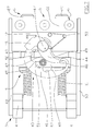
figure 2 shows a view of the device offigure 1 in a hooking condition of two of its members and sectioned by a median and vertical plane; -
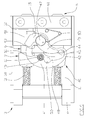
figures 3 and 4 show a sectional and at different scale views of the device offigure 2 in conditions respectively rotated and locked; -
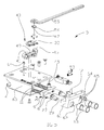
figure 5 shows an axonometric and exploded view of the device offigure 1 ; -
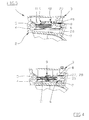
figure 6 shows a top view of a second member of the device offigure 1 in a protruding extreme condition of its latch means and in which some parts have been removed to make better in evidence others; -
figures 7 ,8 and9 show top views of the second member offigure 6 in conditions respectively of locking, of unlocking and of safety support. - With reference to
figures 1-9 ,numeral 1 indicates the device, object of the present invention, for connecting a tool T to an operating means A. - Said
device 1 includes afirst member 2 and asecond member 3, to be fixed, for example by means of welding and/or screw means, to tool T and to the operating means A. - The first 2 and second 3 members have respective hooking means 4, 5 for the reciprocal removable hooking.
- The
second member 3, in general higher than the first 2 in operating conditions, is provided with two latch means 6 parallel and reciprocally connected by amovable means 9 sliding in the body of suchsecond member 3 between an internal condition I and a protruding condition E of latch means 6. In the protruding condition E, end or better intermediate, the latch means 6 can engage, in a hooking and approaching condition among themembers matching means 8 of thefirst member 2 for carrying out, in cooperating withhooking means - The
device 1 includes moreoverelastic means 11 consisting in two helical springs acting in compression between a fixed portion of thesecond member 3 and the two latch means 6, or on themovable means 9, in direction of the protruding condition E of latch means 6. - The
device 1 includes also locking means 40 destined at least to make a stop condition in the protruding condition E of themovable means 9 and of latch means 6 at least in the connecting condition C of thedevice 1. - Such locking means 40 include an
oscillating body 41, pivotally connected to a fixed part of thesecond member 3 by means of arotation pin 47 that is parallel to the slidingmean 45, and is perpendicular to the direction of the motion of latch means 6. - The sliding
mean 45 is fixed between the action lines of the two helical springs ofelastic means 11. - The oscillating
body 41 is centrally provided with a passing throughshaped hole 48 having elongate slot shape with curved plan and equipped with concave extensions which carry out seats. - The shaped hole has a folded and elongated edge constituting a
cam surface 42, ablock seat 43, anunlock seat 44 and a plurality ofsafety stop seats safety stop seats movable means 9, which is locked to the latch means 6 reciprocally fixing these last, is rigidly connected with asliding mean 45 which, therefore, is rigidly constrained to translate with the latch means 6. - The
sliding mean 45 is housed in theshaped hole 48 and is actuated by thecam surface 42, following the rotation of the oscillatingbody 41, for sliding with contrast ofelastic means 11, from thelocking seat 43, in which the latch means 6 are in the maximum protruding condition E, atunlock seat 44 in which the latch means 6 are in the internal condition I. - The
locking 43 andunlock 44 seats are placed at the ends of thecam surface 42 and define the rotation end positions of the oscillatingbody 41 and translation positions of latch means 6. - The end of the blocking
seat 43 adjacent to thecam surface 42 and through which the sliding mean 45 exits from said blocking seat, is equipped with a stop means 46 slightly protruding in almost parallel direction and with direction opposite to the action lines ofelastic means 11. Such stop means 46 is designated, in the internal condition I, to match the slidingmean 45 elastically holding in the blockingseat 43. - The edge of the
shaped hole 48, forming thecam surface 42, thelocking 43 and unlocking 44 seats, the stop means 46 and thesafety stop seats mean 45 or parallel to the rotation axis of the oscillatingbody 41 around therespective rotation pin 47. - The sliding
mean 45 includes a rolling cylindrical body, for example a nitrided bush, freely rotating around to the axis of such slidingmean 45 and that can rotate matching the edge of theshaped hole 48. - The
locking 43, ofunlock 44 and ofsafety stop mean 45. In particular thelocking 43,unlock 44 andsafety stop stop means 46 consists in an end of theunlock seat 44 directed so that the tangent of thisunlock seat 44 andcam surface 42 in their conjunction point are angled and make an angle preferably obtuse in order to require a light compression ofelastic means 11 when the sliding mean 45 exits from theunlock seat 44. - The tangent of the blocking
seat 43 andcam surface 42 in their conjunction point are almost coinciding. - The
rotation pin 47 is connected at the end of the oscillatingbody 41 near to the blockingseat 43. - The
device 1 includes also a cam means 49 fixed to the oscillatingbody 41 and provided with an edge reproducing thecam surface 42 to which is exactly aligned for increasing the sliding surface for the slidingmeans 45. - The locking means 40 include a
spring means 53 acting between a fixed portion of thesecond member 3 and the oscillatingbody 41 for transmitting to this latter a rotation couple with direction according to the direction towards the protruding condition E. - Such couple acts so that the
oscillating body 41 always matches almost thesliding mean 45 so making the device almost free of vibrations induced by hammers or other tools. - Each helicoidal spring of
elastic means 11 is partially housed in a longitudinal cavity of the respective latch means 6. - The matching means 8 has two seats 7, each for the passage of a respective latch means 6.
- The
second member 3 is provided with abox body 60 having a portion, for example in sheet or bent and welded steel plate, to which is fixed, by means of screws, anexit wall 61 provided with twopassages 62 for the latch means 6. - The length of the
sliding mean 45 is predetermined so that it is almost reaching a fixed part of thebox body 60. In such way in case of excessive stresses oflatches 6, the sliding mean 45 contacts such fixed part discharging thereon the forces acting onto latches preventing the excessive oscillation. - The cross-sections of two latch means 6 and of the
respective passages 62 are circular. - The
passages 62 are equipped with respective annular seal means destined to tightness with the two latch means 6. - Each
passage 62 is internally provided with twotubular bodies 63 of low friction material for the sliding of the respective latch means 6. - Each of the latch means 6 is equipped with a concave annular seat for annular seal means, for example of the said O-ring type, fit to the sliding tightness with the internal surface of the respective passage. As an alternative, the invention provides that the two
tubular bodies 63 of eachpassage 62 are spaced to form between them a seat for a respective annular sealing means. - The
box body 60 is almost oiltight, or preferably grease-tight, and is equipped with entries for introducing lubrificant or preferably grease nipples G for filling thebox body 60 with grease for the lubrication and to prevent, in cooperating with the seal means, the incoming of powders, sands or mud. - The device includes also a mobile scanning lever means 12, associated with the
second member 3, having an external end towards thematching means 8 at least in conditions next to approaching condition, and having the opposite ends acting onto the locking means 40. - The scanning lever means 12 is actuated, at least near the approaching condition of members, by its matching means with the
matching means 8 for acting onto theblocking means 40 eventually with itsunlock seat 44 engaged by the slidingmean 45 and for unlocking the latch means 6 so allowing toelastic means 11 to translate such latch means 6 so engaging them in the respective seats 7 realizing the connecting condition C. - The scanning lever means 12 is slidingly housed in a through-
hole 64 of theexit wall 61. - This passing-through
hole 64 is equipped with two secondtubular bodies 63 spaced to form between them a seat for a respective annular sealing means matching the scanning lever means 12. As an alternative the seat for the annular sealing means can be obtained in the shaft of the scanning lever means 12. - The through-
hole 64 is almost parallel to thepassages 62 for the latch means 6. - The
rotation pin 47 of theoscillating body 41 has a drivinghead 54 accessible from outside of the device and to be engageable with a lever-operatedtool 55 for the activation in rotation of theoscillating body 41. - The
box body 60 has a first opening for the passage of therotation pin 47 and has a second opening, not illustrated and preferably separated by the first opening, of such dimensions as to allow the access inside thebox body 60 allowing to bring directly the latch means 6 in the internal condition I also without acting on therotation pin 47, for example in case of breaking this latter. - A shaped
plate 32, re-moveably fixed on thebox body 60, closes the second opening and has operating graphic indications of saidrotation pin 47. - As an alternative to the second opening, the invention provides that the
exit wall 61 has a screw threaded through-hole, not shown, almost parallel to the latch means 6 and directed towards a portion of theoscillating body 41 spaced from therotation pin 47. The screw threaded through-hole is fit to be engaged by a threaded bar for allowing to bring directly the latch means 6 in the internal condition I also without acting on therotation pin 47, for example when this latter will be broken. - The upper portion, fit to be turned towards the operating means A, of the external end of each latch means 6 has at least one
respective chute 27 for matching aflat portion 28 of the seat 7. It is provided that the matching means 8 has a single seat 7 for all the latch means 6 or that has more seats 7, each for the passage of one or more respective latch means 6. - In the connecting condition C, each
chute 27 is parallel and matches with the correspondingflat portion 28. - Each latch means 6 has a
safety plane 29 outwardly extending beginning from thechute 27 and parallel directed along the longitudinal axis of the respective latch means 6. - The
device 1 includes also an arm means 15 fixed to theoscillating body 41 and fit to be connected to an operating actuator in rotation of saidoscillating body 41. - A possible operation of the
device 1 provides that when it is in the connecting condition C, with the engaged latch means in the respective seats 7 of the matching means 8, the slidingmean 45 is matching thecam surface 42 near the blockingseat 43 and almost faced to the safety stop seats 50, 51, 52. If the vibrations, pulses and/or forces produced by the work of tool T and of action means A push inwardly the latch means, the slidingmean 45 translates inwardly so engaging one of the safety stop seats 50, 51, 52, in general the intermediate 51, preventing the additional inwardly translation of latch means 6 and preventing the disengaging from the respective seats 7 of the matching means 8. If thedevice 1 is carried out with excessive tolerances, and in particular with longitudinal sizes different from those projected, or if the wearing of device has altered the measures, the inwardly pushes and translations of latch means 6, in the connecting condition C, can bring the sliding mean 45 to match with one of the side safety stop seats 50, 52 ensuring the security of the connection also in case of excessive tolerances and wearing. - The release of the device is carried out by rotating, by means of
tool 55 or actuator connected to the arm means 15, theoscillating body 41 until to engage the sliding mean 45 into theunlock seat 44 and carrying the latch means into the internal condition; the detachment is completed by disengaging the hookingmeans unlock seat 44 by the stop means 46. - Starting from the last detachment condition described above, to obtain the connecting condition C is sufficient to hook again the hooking
means oscillating body 41 so whose consequent rotation frees theunlock 44 seat from the sliding mean 45 allowing the elastic means 11 to bring the latch means 6 into the protruding condition E engaging the respective seats 7 of the matching means 8 of thefirst member 2. - An advantage of this invention is to supply a device with safety block for connecting tool to an operating means provided with means for moving in a simple way and reliable the sliding latch between the protruding and internal conditions.
- Additional advantage is to supply a device which can work correctly, ensuring the safety block of the latch, also in case of production of its pieces with high tolerances.
- Other advantage is to supply a device able to correctly operate also after that a prolonged and heavy usage has wear out the components.
- Other advantage is to supply a device fit for avoiding or reducing the incoming of earth, of powders, of sands and of debris, and for ensuring a reliable operation at every condition.
Claims (15)
- Device with safety block for connecting a tool (T) to an operating means (A); said device (1) includes a first member (2) and a second member (3) fit to be fixed one to the tool (T) and the other to the operating means (A) and having respective hooking means (4, 5) for the reciprocal removable hooking; one of these members (3, 2) is furthermore provided with at least one latch means (6) sliding therein (3, 2) between an internal condition (I) and a protruding condition (E) in which the at least a latch means (6) can engage at least one seat (7) of a matching means (8) of the other member (2, 3) for carrying out, cooperating with the hooking means (4, 5), the connecting condition (C) between the tool and the operating means; the member (3, 2) that is provided with at least a latch means (6) including moreover elastic means (11) acting on the at least a latch means (6) in the direction of protruding condition (E) and safety locking means (40) for carrying out at least one stop condition of the at least one latch means (6) in the connecting condition (C); said device (1) being characterised in that the locking means (40) include an oscillating body (41), pivotally connected to a fixed part of the respective member (3, 2), and having at least one cam surface (42) and at least one blocking seat (43) and an unlocking seat (44); the at least a latch means (6) is rigidly connected to a sliding mean (45) actuated by the cam surface (42), between the locking (43) and unlocking (44) seats following the rotation of the oscillating body (41) for moving, with contrast of elastic means (11), the at least a latch means (6) from the protruding condition (E) to the internal condition (I) and vice-versa.
- Device according to claim 1 characterised in that the cam surface (42), the locking seats (43) and unlocking seats (44) are made on the edge of a shaped hole (48), having an elongate slot shape carried out in the oscillating body (41) where such locking seats (43) and unlocking seats (44) are placed at the ends of the cam surface (42) having elongate form and preferably curved.
- Device according to claim 2 characterised in that the edge portion of the shaped hole (48) faced to the cam surface (42) has a plurality of safety stop seats (50, 51, 52).
- Device according to claim 3 characterised in that the safety stop seats (50, 51, 52) preferably are adjacent and in number of three and that the locking seats (43), unlocking seats (44) and safety stop seats (50, 51, 52) are almost shaped complementary to a portion of the sliding mean (45) possibly including a rolling cylindrical body around the axis of the sliding mean (45) and that can rotate with matching the edge of the shaped hole (48).
- Device according to any of the previous claims characterised in that the ends of the blocking seat (43) for the exit of the sliding mean (45) is equipped with a stop means (46) slightly protruding in direction almost parallel and opposite direction to those action directions of elastic means (11) and designated, in the internal condition (I), to match the sliding mean (45) elastically and re-moveably holding in the blocking seat (43).
- Device according to claim 5 characterised in that the stop means (46) is at least partially carried out at the border of the shaped hole (48) made in the oscillating body (41).
- Device according to any of the previous claims characterised in that includes a cam means (49) fixed to the oscillating body (41) and provided with an edge reproducing the cam surface (42) to which exactly is aligned for increasing the sliding surface for the sliding means (45).
- Device according to any of the previous claims characterised in that includes a scanning lever means (12) movable associated to one of the members (3, 2), directed towards the backing means (8) at least in conditions next to approaching one, and acting onto the blocking means (40); said scanning lever means (12) being driven, at least near the approaching condition of members, by its matching with matching means (8) for acting onto the blocking means (40) and unlocking the at least a latch means (6) so allowing the elastic means (11) to translate such at least one latch means (6) engaging this latter in the at least a seat (7) making the connecting condition (C).
- Device according to claim 8 characterised in that the member (3, 2) having the at least a latch means (6) includes a box body (60) provided with an exit wall (61) equipped with at least one passage (62) for the at least a latch means (6); the scanning lever means (12) is slidingly housed in a through-hole (64) parallel to the at least one passage (62) for a latch means (6) carried out in the exit wall (61) and provided with two second tubular bodies (65) spaced to form among them a seat for a respective annular sealing means matching the scanning lever means (12).
- Device according to claim 9 characterised in that the oscillating body (41) rotates around a rotation pin (47) that is parallel to the sliding mean (45), is connected at an end of the oscillating body (41) and is perpendicular to the direction of the motion of the at least one latch means (6), such rotation pin (47) has a driving head (54) engageable with a tool (55) for operating in rotation the oscillating body (41) and accessible from outside of the device through a first opening of the box body (60) which has s a second opening of such dimensions as to allow the access inside the box body (60) for allowing to bring directly the at least one latch means (6) into the internal condition (I) also without acting on the rotation pin (47); the box body (60) has a shaped plate (32) re-moveably fixed thereto for closing the second opening; such shaped plate (32) being able to carry operating graphic indications of said rotation pin (47).
- Device according to claims from 7 to 10 characterised in that the exit wall (61) has a screw threaded through-hole, parallel to the at least one latch means (6) and directed towards a portion of the oscillating body (41) spaced from the rotation pin (47); said threaded through-hole being fit to be engaged by a threaded bar to bring directly the latch means (6) into the internal condition (I) also without acting on the rotation pin (47), for example in case of breaking this latter.
- Device according to claim 1 characterised in that includes an arm means (15) fixed to the oscillating body (41) and fit to be connected to an operating actuator of rotation of said oscillating body.
- Device according to claim 1 characterised in that the locking means (40) include a spring means (53) acting between a fixed portion of the member (3, 2) having the at least one latch means (6) and the oscillating body (41) for transmitting to this latter a rotation couple with according direction to which towards the protruding condition (E).
- Device according to claim 9 characterised in that the sliding mean (45) is placed between the action lines of two helical springs of elastic means (11), that the length of the sliding mean (45) is predetermined so that almost reaches a fixed part of the box body (60), that the sliding mean (45) is fixed, by means of a movable means (9) sliding in the body of the respective member (3, 2), with two latch means (6) elongate shaped and at least almost parallel, slideable in one or more seats (7) of the matching means (8) where the elastic means (11) include two helical springs acting in compression between a fixed portion of the member (3, 2) having the latch means (6) and the latter and in which each helicoidal spring of the elastic means (11) is partially housed in a longitudinal cavity of the respective latch means (6) and that each passage (62) situated in the box body (60) for the at least one latch means (6) is equipped with two tubular bodies (63) spaced to form among them a concave seat for a respective annular sealing means in which tight slides the respective latch means (6).
- Device according to claim 1 characterised in that the upper portion, fit to be turned towards the operating means (A), of the external end of each latch means (6) has at least one respective chute (27) for matching a flat portion (28) of the respective seat (7) equally inclined; in the connecting condition (C), each chute (27) is parallel and matches the corresponding flat portion (28) and in that each latch means (6) has a safety plane (29) outwardly extending beginning from the chute (27) and oriented parallel to the longitudinal axis of the respective latch means (6).
Applications Claiming Priority (1)
| Application Number | Priority Date | Filing Date | Title |
|---|---|---|---|
| IT000728A ITBO20070728A1 (en) | 2007-10-30 | 2007-10-30 | DEVICE WITH SAFETY LOCK TO CONNECT A TOOL TO A HALF OF OPERATION. |
Publications (3)
| Publication Number | Publication Date |
|---|---|
| EP2055842A2 true EP2055842A2 (en) | 2009-05-06 |
| EP2055842A3 EP2055842A3 (en) | 2013-10-02 |
| EP2055842B1 EP2055842B1 (en) | 2016-12-28 |
Family
ID=39938439
Family Applications (1)
| Application Number | Title | Priority Date | Filing Date |
|---|---|---|---|
| EP08167866.6A Active EP2055842B1 (en) | 2007-10-30 | 2008-10-29 | Device with safety block for connecting a tool to an operating means |
Country Status (3)
| Country | Link |
|---|---|
| EP (1) | EP2055842B1 (en) |
| ES (1) | ES2611940T3 (en) |
| IT (1) | ITBO20070728A1 (en) |
Cited By (11)
| Publication number | Priority date | Publication date | Assignee | Title |
|---|---|---|---|---|
| WO2015024981A1 (en) * | 2013-08-23 | 2015-02-26 | Geith International Limited | Safety coupling mechanism |
| FR3014125A1 (en) * | 2013-12-04 | 2015-06-05 | Xavier Pingret | DEVICE FOR QUICK ATTACHING A TOOL OF CIVIL ENGINEERING OR HANDLING |
| EP2910688A1 (en) * | 2014-02-24 | 2015-08-26 | Cangini Benne S.R.L. | Lock and release system |
| DE102014116245A1 (en) * | 2014-11-07 | 2016-05-12 | Bela Cseri | Securing device of a quick-change device of a working machine and quick-change device |
| BE1023965B1 (en) * | 2016-03-21 | 2017-09-26 | Zele Bart Julia R Van | Coupling for an earth-moving machine to connect interchangeable tools to the earth-moving machine |
| EP3399106A1 (en) * | 2017-05-05 | 2018-11-07 | Martin GmbH | Quick swap coupling for fixing an attachment |
| WO2019206425A1 (en) * | 2018-04-27 | 2019-10-31 | Volvo Construction Equipment Ab | Removable tool assembly for construction machines |
| US20220307220A1 (en) * | 2019-05-28 | 2022-09-29 | Kobelco Construction Machinery Co., Ltd. | Construction machine |
| IT202100031157A1 (en) * | 2021-12-13 | 2023-06-13 | Simex Srl | QUICK CONNECTION FOR THE REVERSIBLE CONNECTION OF A TOOL TO A HANDLING ARM, PARTICULARLY FOR EARTH-MOVING AND SIMILAR MACHINES AND BUCKET ASSEMBLY INCLUDING SUCH QUICK CONNECTION |
| WO2023200391A1 (en) * | 2022-04-13 | 2023-10-19 | Steelwrist Ab | Lock indicator arrangement and method for a quick coupler and quick coupler comprising the same |
| IT202300018048A1 (en) * | 2023-09-01 | 2025-03-01 | Loris Barchi | SEMI-AUTOMATIC AND REVERSIBLE QUICK COUPLING FOR EXCAVATOR ARM WITH DOUBLE SAFETY SYSTEM |
Family Cites Families (3)
| Publication number | Priority date | Publication date | Assignee | Title |
|---|---|---|---|---|
| CH687775A5 (en) * | 1994-01-11 | 1997-02-14 | Grand Pierre Le | Quick-change system for Loeffelbagger. |
| JP3283393B2 (en) * | 1995-01-31 | 2002-05-20 | 株式会社坂戸工作所 | Connector for construction work machine |
| ITBO20040531A1 (en) * | 2004-08-20 | 2004-11-20 | Cangini Benne Srl | SAFETY DEVICE FOR TOOL CONNECTION |
-
2007
- 2007-10-30 IT IT000728A patent/ITBO20070728A1/en unknown
-
2008
- 2008-10-29 ES ES08167866.6T patent/ES2611940T3/en active Active
- 2008-10-29 EP EP08167866.6A patent/EP2055842B1/en active Active
Cited By (20)
| Publication number | Priority date | Publication date | Assignee | Title |
|---|---|---|---|---|
| WO2015024981A1 (en) * | 2013-08-23 | 2015-02-26 | Geith International Limited | Safety coupling mechanism |
| GB2517499B (en) * | 2013-08-23 | 2017-08-23 | Geith Int Ltd | Safety coupling mechanism |
| US10352020B2 (en) | 2013-08-23 | 2019-07-16 | Geith International Limited | Safety coupling mechanism |
| FR3014125A1 (en) * | 2013-12-04 | 2015-06-05 | Xavier Pingret | DEVICE FOR QUICK ATTACHING A TOOL OF CIVIL ENGINEERING OR HANDLING |
| EP2910688A1 (en) * | 2014-02-24 | 2015-08-26 | Cangini Benne S.R.L. | Lock and release system |
| DE102014116245A1 (en) * | 2014-11-07 | 2016-05-12 | Bela Cseri | Securing device of a quick-change device of a working machine and quick-change device |
| DE102014116245B4 (en) * | 2014-11-07 | 2016-11-10 | Bela Cseri | Quick change device of a work machine |
| BE1023965B1 (en) * | 2016-03-21 | 2017-09-26 | Zele Bart Julia R Van | Coupling for an earth-moving machine to connect interchangeable tools to the earth-moving machine |
| EP3399106A1 (en) * | 2017-05-05 | 2018-11-07 | Martin GmbH | Quick swap coupling for fixing an attachment |
| CH713758A1 (en) * | 2017-05-05 | 2018-11-15 | Martin Umwelt & Energietech | Quick-change coupling for attaching an attachment to a construction machine, preferably on an excavator arm. |
| WO2019206425A1 (en) * | 2018-04-27 | 2019-10-31 | Volvo Construction Equipment Ab | Removable tool assembly for construction machines |
| CN111712602A (en) * | 2018-04-27 | 2020-09-25 | 沃尔沃建筑设备公司 | Removable tool assemblies for construction machinery |
| CN111712602B (en) * | 2018-04-27 | 2023-04-04 | 沃尔沃建筑设备公司 | Removable tool assembly for construction machine |
| US11840821B2 (en) | 2018-04-27 | 2023-12-12 | Volvo Construction Equipment Ab | Removable tool assembly for construction machines |
| US20220307220A1 (en) * | 2019-05-28 | 2022-09-29 | Kobelco Construction Machinery Co., Ltd. | Construction machine |
| US12203234B2 (en) * | 2019-05-28 | 2025-01-21 | Kobelco Construction Machinery Co., Ltd. | Construction machine |
| IT202100031157A1 (en) * | 2021-12-13 | 2023-06-13 | Simex Srl | QUICK CONNECTION FOR THE REVERSIBLE CONNECTION OF A TOOL TO A HANDLING ARM, PARTICULARLY FOR EARTH-MOVING AND SIMILAR MACHINES AND BUCKET ASSEMBLY INCLUDING SUCH QUICK CONNECTION |
| WO2023111813A1 (en) * | 2021-12-13 | 2023-06-22 | Simex Srl | Quick coupling for the reversible connection of a tool to a movement arm, particularly for earth-moving machines and the like and bucket assembly comprising such a quick coupling |
| WO2023200391A1 (en) * | 2022-04-13 | 2023-10-19 | Steelwrist Ab | Lock indicator arrangement and method for a quick coupler and quick coupler comprising the same |
| IT202300018048A1 (en) * | 2023-09-01 | 2025-03-01 | Loris Barchi | SEMI-AUTOMATIC AND REVERSIBLE QUICK COUPLING FOR EXCAVATOR ARM WITH DOUBLE SAFETY SYSTEM |
Also Published As
| Publication number | Publication date |
|---|---|
| ES2611940T3 (en) | 2017-05-11 |
| EP2055842A3 (en) | 2013-10-02 |
| ITBO20070728A1 (en) | 2009-04-30 |
| EP2055842B1 (en) | 2016-12-28 |
Similar Documents
| Publication | Publication Date | Title |
|---|---|---|
| EP2055842B1 (en) | Device with safety block for connecting a tool to an operating means | |
| KR101928795B1 (en) | rotation rink for excavator | |
| US4951886A (en) | Concrete crusher | |
| NO337970B1 (en) | Wear unit and its components, designed for machines for moving materials such as earth and stone | |
| EP1900880B1 (en) | Device for connecting a tool to a driving means of a working machine | |
| US7735249B2 (en) | Quick-change device | |
| US8469623B2 (en) | Quick coupling device | |
| US6336785B1 (en) | Quick coupler for heavy equipment | |
| KR102838610B1 (en) | Coupler | |
| EP2119834B1 (en) | An attachment organ for coupling a tool to an operating arm with a safety block | |
| MX2008016131A (en) | Lock for securing wear parts to earth-working equipment. | |
| KR101523072B1 (en) | Quick coupler for excavation | |
| JP2021139284A (en) | Quick change device | |
| US7621689B2 (en) | Attachment coupler | |
| KR102338301B1 (en) | Cover opening/closing apparatus of oil-hydraulic coupling block for quick change device | |
| AU2021240293A1 (en) | Quick-hitch for construction vehicle tools | |
| EA038441B1 (en) | Wear part for use with earthmoving equipment | |
| EP2378004A2 (en) | Quick coupling device for connecting a tool to a handling equipment, such as the arm of an excavator | |
| EP2990538B1 (en) | Fast lock and release device for a soil shifting machine | |
| US4063373A (en) | Mechanism to restrain slamming of shovel dipper doors | |
| KR20200053356A (en) | Safe-Locking Type Quick Coupler | |
| EP1627959B1 (en) | Safety device for the connection of tools | |
| CN109296014A (en) | Coupler assembly for coupling an arm to a work tool | |
| EP2832931B1 (en) | Quick coupler for connection of an implement to a work machine | |
| CN116062603B (en) | Hooks and cranes |
Legal Events
| Date | Code | Title | Description |
|---|---|---|---|
| PUAI | Public reference made under article 153(3) epc to a published international application that has entered the european phase |
Free format text: ORIGINAL CODE: 0009012 |
|
| AK | Designated contracting states |
Kind code of ref document: A2 Designated state(s): AT BE BG CH CY CZ DE DK EE ES FI FR GB GR HR HU IE IS IT LI LT LU LV MC MT NL NO PL PT RO SE SI SK TR |
|
| AX | Request for extension of the european patent |
Extension state: AL BA MK RS |
|
| PUAL | Search report despatched |
Free format text: ORIGINAL CODE: 0009013 |
|
| AK | Designated contracting states |
Kind code of ref document: A3 Designated state(s): AT BE BG CH CY CZ DE DK EE ES FI FR GB GR HR HU IE IS IT LI LT LU LV MC MT NL NO PL PT RO SE SI SK TR |
|
| AX | Request for extension of the european patent |
Extension state: AL BA MK RS |
|
| RIC1 | Information provided on ipc code assigned before grant |
Ipc: E02F 3/36 20060101AFI20130827BHEP |
|
| AKY | No designation fees paid | ||
| REG | Reference to a national code |
Ref country code: DE Ref legal event code: R108 |
|
| REG | Reference to a national code |
Ref country code: DE Ref legal event code: R108 Ref document number: 602008048106 Country of ref document: DE Effective date: 20140611 Ref country code: DE Ref legal event code: R108 Effective date: 20140611 |
|
| 17P | Request for examination filed |
Effective date: 20140709 |
|
| RBV | Designated contracting states (corrected) |
Designated state(s): AT BE BG CH CY CZ DE DK EE ES FI FR GB GR HR HU IE IS IT LI LT LU LV MC MT NL NO PL PT RO SE SI SK TR |
|
| GRAP | Despatch of communication of intention to grant a patent |
Free format text: ORIGINAL CODE: EPIDOSNIGR1 |
|
| INTG | Intention to grant announced |
Effective date: 20160707 |
|
| STAA | Information on the status of an ep patent application or granted ep patent |
Free format text: STATUS: GRANT OF PATENT IS INTENDED |
|
| GRAS | Grant fee paid |
Free format text: ORIGINAL CODE: EPIDOSNIGR3 |
|
| GRAA | (expected) grant |
Free format text: ORIGINAL CODE: 0009210 |
|
| STAA | Information on the status of an ep patent application or granted ep patent |
Free format text: STATUS: THE PATENT HAS BEEN GRANTED |
|
| AK | Designated contracting states |
Kind code of ref document: B1 Designated state(s): AT BE BG CH CY CZ DE DK EE ES FI FR GB GR HR HU IE IS IT LI LT LU LV MC MT NL NO PL PT RO SE SI SK TR |
|
| REG | Reference to a national code |
Ref country code: GB Ref legal event code: FG4D |
|
| REG | Reference to a national code |
Ref country code: CH Ref legal event code: EP |
|
| REG | Reference to a national code |
Ref country code: DE Ref legal event code: R082 Ref document number: 602008048106 Country of ref document: DE Representative=s name: BRAUN-DULLAEUS PANNEN PATENT- UND RECHTSANWAEL, DE Ref country code: DE Ref legal event code: R082 Ref document number: 602008048106 Country of ref document: DE Representative=s name: BRAUN-DULLAEUS PANNEN EMMERLING PATENT- UND RE, DE |
|
| REG | Reference to a national code |
Ref country code: AT Ref legal event code: REF Ref document number: 857417 Country of ref document: AT Kind code of ref document: T Effective date: 20170115 |
|
| REG | Reference to a national code |
Ref country code: IE Ref legal event code: FG4D |
|
| REG | Reference to a national code |
Ref country code: CH Ref legal event code: NV Representative=s name: ORITI PATENTS - FRANCO ORITI, CH |
|
| REG | Reference to a national code |
Ref country code: DE Ref legal event code: R096 Ref document number: 602008048106 Country of ref document: DE |
|
| PG25 | Lapsed in a contracting state [announced via postgrant information from national office to epo] |
Ref country code: LV Free format text: LAPSE BECAUSE OF FAILURE TO SUBMIT A TRANSLATION OF THE DESCRIPTION OR TO PAY THE FEE WITHIN THE PRESCRIBED TIME-LIMIT Effective date: 20161228 |
|
| REG | Reference to a national code |
Ref country code: LT Ref legal event code: MG4D |
|
| PG25 | Lapsed in a contracting state [announced via postgrant information from national office to epo] |
Ref country code: LT Free format text: LAPSE BECAUSE OF FAILURE TO SUBMIT A TRANSLATION OF THE DESCRIPTION OR TO PAY THE FEE WITHIN THE PRESCRIBED TIME-LIMIT Effective date: 20161228 Ref country code: GR Free format text: LAPSE BECAUSE OF FAILURE TO SUBMIT A TRANSLATION OF THE DESCRIPTION OR TO PAY THE FEE WITHIN THE PRESCRIBED TIME-LIMIT Effective date: 20170329 Ref country code: NO Free format text: LAPSE BECAUSE OF FAILURE TO SUBMIT A TRANSLATION OF THE DESCRIPTION OR TO PAY THE FEE WITHIN THE PRESCRIBED TIME-LIMIT Effective date: 20170328 Ref country code: SE Free format text: LAPSE BECAUSE OF FAILURE TO SUBMIT A TRANSLATION OF THE DESCRIPTION OR TO PAY THE FEE WITHIN THE PRESCRIBED TIME-LIMIT Effective date: 20161228 |
|
| REG | Reference to a national code |
Ref country code: NL Ref legal event code: MP Effective date: 20161228 |
|
| REG | Reference to a national code |
Ref country code: ES Ref legal event code: FG2A Ref document number: 2611940 Country of ref document: ES Kind code of ref document: T3 Effective date: 20170511 |
|
| PG25 | Lapsed in a contracting state [announced via postgrant information from national office to epo] |
Ref country code: HR Free format text: LAPSE BECAUSE OF FAILURE TO SUBMIT A TRANSLATION OF THE DESCRIPTION OR TO PAY THE FEE WITHIN THE PRESCRIBED TIME-LIMIT Effective date: 20161228 Ref country code: FI Free format text: LAPSE BECAUSE OF FAILURE TO SUBMIT A TRANSLATION OF THE DESCRIPTION OR TO PAY THE FEE WITHIN THE PRESCRIBED TIME-LIMIT Effective date: 20161228 |
|
| PG25 | Lapsed in a contracting state [announced via postgrant information from national office to epo] |
Ref country code: NL Free format text: LAPSE BECAUSE OF FAILURE TO SUBMIT A TRANSLATION OF THE DESCRIPTION OR TO PAY THE FEE WITHIN THE PRESCRIBED TIME-LIMIT Effective date: 20161228 |
|
| PG25 | Lapsed in a contracting state [announced via postgrant information from national office to epo] |
Ref country code: CZ Free format text: LAPSE BECAUSE OF FAILURE TO SUBMIT A TRANSLATION OF THE DESCRIPTION OR TO PAY THE FEE WITHIN THE PRESCRIBED TIME-LIMIT Effective date: 20161228 Ref country code: SK Free format text: LAPSE BECAUSE OF FAILURE TO SUBMIT A TRANSLATION OF THE DESCRIPTION OR TO PAY THE FEE WITHIN THE PRESCRIBED TIME-LIMIT Effective date: 20161228 Ref country code: EE Free format text: LAPSE BECAUSE OF FAILURE TO SUBMIT A TRANSLATION OF THE DESCRIPTION OR TO PAY THE FEE WITHIN THE PRESCRIBED TIME-LIMIT Effective date: 20161228 Ref country code: IS Free format text: LAPSE BECAUSE OF FAILURE TO SUBMIT A TRANSLATION OF THE DESCRIPTION OR TO PAY THE FEE WITHIN THE PRESCRIBED TIME-LIMIT Effective date: 20170428 Ref country code: RO Free format text: LAPSE BECAUSE OF FAILURE TO SUBMIT A TRANSLATION OF THE DESCRIPTION OR TO PAY THE FEE WITHIN THE PRESCRIBED TIME-LIMIT Effective date: 20161228 |
|
| PG25 | Lapsed in a contracting state [announced via postgrant information from national office to epo] |
Ref country code: PT Free format text: LAPSE BECAUSE OF FAILURE TO SUBMIT A TRANSLATION OF THE DESCRIPTION OR TO PAY THE FEE WITHIN THE PRESCRIBED TIME-LIMIT Effective date: 20170428 Ref country code: PL Free format text: LAPSE BECAUSE OF FAILURE TO SUBMIT A TRANSLATION OF THE DESCRIPTION OR TO PAY THE FEE WITHIN THE PRESCRIBED TIME-LIMIT Effective date: 20161228 |
|
| REG | Reference to a national code |
Ref country code: DE Ref legal event code: R097 Ref document number: 602008048106 Country of ref document: DE |
|
| REG | Reference to a national code |
Ref country code: FR Ref legal event code: PLFP Year of fee payment: 10 |
|
| PLBE | No opposition filed within time limit |
Free format text: ORIGINAL CODE: 0009261 |
|
| STAA | Information on the status of an ep patent application or granted ep patent |
Free format text: STATUS: NO OPPOSITION FILED WITHIN TIME LIMIT |
|
| PG25 | Lapsed in a contracting state [announced via postgrant information from national office to epo] |
Ref country code: DK Free format text: LAPSE BECAUSE OF FAILURE TO SUBMIT A TRANSLATION OF THE DESCRIPTION OR TO PAY THE FEE WITHIN THE PRESCRIBED TIME-LIMIT Effective date: 20161228 |
|
| 26N | No opposition filed |
Effective date: 20170929 |
|
| PG25 | Lapsed in a contracting state [announced via postgrant information from national office to epo] |
Ref country code: SI Free format text: LAPSE BECAUSE OF FAILURE TO SUBMIT A TRANSLATION OF THE DESCRIPTION OR TO PAY THE FEE WITHIN THE PRESCRIBED TIME-LIMIT Effective date: 20161228 |
|
| PG25 | Lapsed in a contracting state [announced via postgrant information from national office to epo] |
Ref country code: MC Free format text: LAPSE BECAUSE OF FAILURE TO SUBMIT A TRANSLATION OF THE DESCRIPTION OR TO PAY THE FEE WITHIN THE PRESCRIBED TIME-LIMIT Effective date: 20161228 |
|
| GBPC | Gb: european patent ceased through non-payment of renewal fee |
Effective date: 20171029 |
|
| REG | Reference to a national code |
Ref country code: IE Ref legal event code: MM4A |
|
| PG25 | Lapsed in a contracting state [announced via postgrant information from national office to epo] |
Ref country code: LU Free format text: LAPSE BECAUSE OF NON-PAYMENT OF DUE FEES Effective date: 20171029 Ref country code: GB Free format text: LAPSE BECAUSE OF NON-PAYMENT OF DUE FEES Effective date: 20171029 |
|
| PG25 | Lapsed in a contracting state [announced via postgrant information from national office to epo] |
Ref country code: MT Free format text: LAPSE BECAUSE OF NON-PAYMENT OF DUE FEES Effective date: 20171029 |
|
| REG | Reference to a national code |
Ref country code: FR Ref legal event code: PLFP Year of fee payment: 11 |
|
| PG25 | Lapsed in a contracting state [announced via postgrant information from national office to epo] |
Ref country code: IE Free format text: LAPSE BECAUSE OF NON-PAYMENT OF DUE FEES Effective date: 20171029 |
|
| PG25 | Lapsed in a contracting state [announced via postgrant information from national office to epo] |
Ref country code: HU Free format text: LAPSE BECAUSE OF FAILURE TO SUBMIT A TRANSLATION OF THE DESCRIPTION OR TO PAY THE FEE WITHIN THE PRESCRIBED TIME-LIMIT; INVALID AB INITIO Effective date: 20081029 |
|
| PG25 | Lapsed in a contracting state [announced via postgrant information from national office to epo] |
Ref country code: BG Free format text: LAPSE BECAUSE OF FAILURE TO SUBMIT A TRANSLATION OF THE DESCRIPTION OR TO PAY THE FEE WITHIN THE PRESCRIBED TIME-LIMIT Effective date: 20161228 |
|
| PG25 | Lapsed in a contracting state [announced via postgrant information from national office to epo] |
Ref country code: CY Free format text: LAPSE BECAUSE OF NON-PAYMENT OF DUE FEES Effective date: 20161228 |
|
| PG25 | Lapsed in a contracting state [announced via postgrant information from national office to epo] |
Ref country code: TR Free format text: LAPSE BECAUSE OF FAILURE TO SUBMIT A TRANSLATION OF THE DESCRIPTION OR TO PAY THE FEE WITHIN THE PRESCRIBED TIME-LIMIT Effective date: 20161228 |
|
| P01 | Opt-out of the competence of the unified patent court (upc) registered |
Effective date: 20230807 |
|
| REG | Reference to a national code |
Ref country code: CH Ref legal event code: U11 Free format text: ST27 STATUS EVENT CODE: U-0-0-U10-U11 (AS PROVIDED BY THE NATIONAL OFFICE) Effective date: 20251101 |
|
| PGFP | Annual fee paid to national office [announced via postgrant information from national office to epo] |
Ref country code: DE Payment date: 20251029 Year of fee payment: 18 |
|
| PGFP | Annual fee paid to national office [announced via postgrant information from national office to epo] |
Ref country code: AT Payment date: 20251029 Year of fee payment: 18 |
|
| PGFP | Annual fee paid to national office [announced via postgrant information from national office to epo] |
Ref country code: IT Payment date: 20251017 Year of fee payment: 18 |
|
| PGFP | Annual fee paid to national office [announced via postgrant information from national office to epo] |
Ref country code: FR Payment date: 20251027 Year of fee payment: 18 |
|
| PGFP | Annual fee paid to national office [announced via postgrant information from national office to epo] |
Ref country code: BE Payment date: 20251027 Year of fee payment: 18 |
|
| PGFP | Annual fee paid to national office [announced via postgrant information from national office to epo] |
Ref country code: CH Payment date: 20251101 Year of fee payment: 18 |
|
| PGFP | Annual fee paid to national office [announced via postgrant information from national office to epo] |
Ref country code: ES Payment date: 20251103 Year of fee payment: 18 |