EP2055372B1 - Rührereinheit aufweisend einen Adapter - Google Patents
Rührereinheit aufweisend einen Adapter Download PDFInfo
- Publication number
- EP2055372B1 EP2055372B1 EP07119828A EP07119828A EP2055372B1 EP 2055372 B1 EP2055372 B1 EP 2055372B1 EP 07119828 A EP07119828 A EP 07119828A EP 07119828 A EP07119828 A EP 07119828A EP 2055372 B1 EP2055372 B1 EP 2055372B1
- Authority
- EP
- European Patent Office
- Prior art keywords
- stirrer
- adapter
- shaft
- guide sleeve
- unit according
- Prior art date
- Legal status (The legal status is an assumption and is not a legal conclusion. Google has not performed a legal analysis and makes no representation as to the accuracy of the status listed.)
- Not-in-force
Links
- 238000006243 chemical reaction Methods 0.000 claims abstract description 47
- 238000007654 immersion Methods 0.000 claims abstract 2
- 230000008878 coupling Effects 0.000 claims description 24
- 238000010168 coupling process Methods 0.000 claims description 24
- 238000005859 coupling reaction Methods 0.000 claims description 24
- 238000003756 stirring Methods 0.000 description 41
- 230000035515 penetration Effects 0.000 description 16
- 239000012429 reaction media Substances 0.000 description 13
- 239000000463 material Substances 0.000 description 6
- XEEYBQQBJWHFJM-UHFFFAOYSA-N Iron Chemical compound [Fe] XEEYBQQBJWHFJM-UHFFFAOYSA-N 0.000 description 5
- 240000006829 Ficus sundaica Species 0.000 description 3
- 238000006073 displacement reaction Methods 0.000 description 3
- 238000011161 development Methods 0.000 description 2
- 230000018109 developmental process Effects 0.000 description 2
- 239000011521 glass Substances 0.000 description 2
- 238000013021 overheating Methods 0.000 description 2
- 239000000376 reactant Substances 0.000 description 2
- FGRBYDKOBBBPOI-UHFFFAOYSA-N 10,10-dioxo-2-[4-(N-phenylanilino)phenyl]thioxanthen-9-one Chemical compound O=C1c2ccccc2S(=O)(=O)c2ccc(cc12)-c1ccc(cc1)N(c1ccccc1)c1ccccc1 FGRBYDKOBBBPOI-UHFFFAOYSA-N 0.000 description 1
- 239000000919 ceramic Substances 0.000 description 1
- 239000007795 chemical reaction product Substances 0.000 description 1
- 229910052742 iron Inorganic materials 0.000 description 1
- 229910052751 metal Inorganic materials 0.000 description 1
- 239000002184 metal Substances 0.000 description 1
- 150000002739 metals Chemical class 0.000 description 1
- 238000000034 method Methods 0.000 description 1
- 239000000203 mixture Substances 0.000 description 1
- 229920000642 polymer Polymers 0.000 description 1
- 239000004810 polytetrafluoroethylene Substances 0.000 description 1
- 229920001343 polytetrafluoroethylene Polymers 0.000 description 1
- 239000000565 sealant Substances 0.000 description 1
- 238000007789 sealing Methods 0.000 description 1
- 238000007086 side reaction Methods 0.000 description 1
- 239000007787 solid Substances 0.000 description 1
- 125000006850 spacer group Chemical group 0.000 description 1
- 239000000126 substance Substances 0.000 description 1
Images


Classifications
-
- B—PERFORMING OPERATIONS; TRANSPORTING
- B01—PHYSICAL OR CHEMICAL PROCESSES OR APPARATUS IN GENERAL
- B01J—CHEMICAL OR PHYSICAL PROCESSES, e.g. CATALYSIS OR COLLOID CHEMISTRY; THEIR RELEVANT APPARATUS
- B01J19/00—Chemical, physical or physico-chemical processes in general; Their relevant apparatus
- B01J19/0053—Details of the reactor
- B01J19/0066—Stirrers
-
- B—PERFORMING OPERATIONS; TRANSPORTING
- B01—PHYSICAL OR CHEMICAL PROCESSES OR APPARATUS IN GENERAL
- B01F—MIXING, e.g. DISSOLVING, EMULSIFYING OR DISPERSING
- B01F27/00—Mixers with rotary stirring devices in fixed receptacles; Kneaders
- B01F27/21—Mixers with rotary stirring devices in fixed receptacles; Kneaders characterised by their rotating shafts
- B01F27/2124—Shafts with adjustable length, e.g. telescopic shafts
-
- B—PERFORMING OPERATIONS; TRANSPORTING
- B01—PHYSICAL OR CHEMICAL PROCESSES OR APPARATUS IN GENERAL
- B01F—MIXING, e.g. DISSOLVING, EMULSIFYING OR DISPERSING
- B01F27/00—Mixers with rotary stirring devices in fixed receptacles; Kneaders
- B01F27/23—Mixers with rotary stirring devices in fixed receptacles; Kneaders characterised by the orientation or disposition of the rotor axis
- B01F27/231—Mixers with rotary stirring devices in fixed receptacles; Kneaders characterised by the orientation or disposition of the rotor axis with a variable orientation during mixing operation, e.g. with tiltable rotor axis
- B01F27/2312—Mixers with rotary stirring devices in fixed receptacles; Kneaders characterised by the orientation or disposition of the rotor axis with a variable orientation during mixing operation, e.g. with tiltable rotor axis the position of the rotating shaft being adjustable in the interior of the receptacle, e.g. to locate the stirrer in different locations during the mixing
-
- B—PERFORMING OPERATIONS; TRANSPORTING
- B01—PHYSICAL OR CHEMICAL PROCESSES OR APPARATUS IN GENERAL
- B01F—MIXING, e.g. DISSOLVING, EMULSIFYING OR DISPERSING
- B01F27/00—Mixers with rotary stirring devices in fixed receptacles; Kneaders
- B01F27/80—Mixers with rotary stirring devices in fixed receptacles; Kneaders with stirrers rotating about a substantially vertical axis
- B01F27/805—Mixers with rotary stirring devices in fixed receptacles; Kneaders with stirrers rotating about a substantially vertical axis wherein the stirrers or the receptacles are moved in order to bring them into operative position; Means for fixing the receptacle
- B01F27/806—Mixers with rotary stirring devices in fixed receptacles; Kneaders with stirrers rotating about a substantially vertical axis wherein the stirrers or the receptacles are moved in order to bring them into operative position; Means for fixing the receptacle with vertical displacement of the stirrer, e.g. in combination with means for pivoting the stirrer about a vertical axis in order to co-operate with different receptacles
-
- B—PERFORMING OPERATIONS; TRANSPORTING
- B01—PHYSICAL OR CHEMICAL PROCESSES OR APPARATUS IN GENERAL
- B01F—MIXING, e.g. DISSOLVING, EMULSIFYING OR DISPERSING
- B01F35/00—Accessories for mixers; Auxiliary operations or auxiliary devices; Parts or details of general application
- B01F35/40—Mounting or supporting mixing devices or receptacles; Clamping or holding arrangements therefor
- B01F35/41—Mounting or supporting stirrer shafts or stirrer units on receptacles
- B01F35/411—Mounting or supporting stirrer shafts or stirrer units on receptacles by supporting only one extremity of the shaft
- B01F35/4111—Mounting or supporting stirrer shafts or stirrer units on receptacles by supporting only one extremity of the shaft at the top of the receptacle
-
- B—PERFORMING OPERATIONS; TRANSPORTING
- B01—PHYSICAL OR CHEMICAL PROCESSES OR APPARATUS IN GENERAL
- B01F—MIXING, e.g. DISSOLVING, EMULSIFYING OR DISPERSING
- B01F2101/00—Mixing characterised by the nature of the mixed materials or by the application field
- B01F2101/2204—Mixing chemical components in generals in order to improve chemical treatment or reactions, independently from the specific application
-
- B—PERFORMING OPERATIONS; TRANSPORTING
- B01—PHYSICAL OR CHEMICAL PROCESSES OR APPARATUS IN GENERAL
- B01F—MIXING, e.g. DISSOLVING, EMULSIFYING OR DISPERSING
- B01F23/00—Mixing according to the phases to be mixed, e.g. dispersing or emulsifying
- B01F23/40—Mixing liquids with liquids; Emulsifying
-
- B—PERFORMING OPERATIONS; TRANSPORTING
- B01—PHYSICAL OR CHEMICAL PROCESSES OR APPARATUS IN GENERAL
- B01F—MIXING, e.g. DISSOLVING, EMULSIFYING OR DISPERSING
- B01F27/00—Mixers with rotary stirring devices in fixed receptacles; Kneaders
- B01F27/05—Stirrers
- B01F27/051—Stirrers characterised by their elements, materials or mechanical properties
- B01F27/054—Deformable stirrers, e.g. deformed by a centrifugal force applied during operation
-
- B—PERFORMING OPERATIONS; TRANSPORTING
- B01—PHYSICAL OR CHEMICAL PROCESSES OR APPARATUS IN GENERAL
- B01F—MIXING, e.g. DISSOLVING, EMULSIFYING OR DISPERSING
- B01F27/00—Mixers with rotary stirring devices in fixed receptacles; Kneaders
- B01F27/05—Stirrers
- B01F27/051—Stirrers characterised by their elements, materials or mechanical properties
- B01F27/054—Deformable stirrers, e.g. deformed by a centrifugal force applied during operation
- B01F27/0541—Deformable stirrers, e.g. deformed by a centrifugal force applied during operation with mechanical means to alter the position of the stirring elements
-
- B—PERFORMING OPERATIONS; TRANSPORTING
- B01—PHYSICAL OR CHEMICAL PROCESSES OR APPARATUS IN GENERAL
- B01F—MIXING, e.g. DISSOLVING, EMULSIFYING OR DISPERSING
- B01F27/00—Mixers with rotary stirring devices in fixed receptacles; Kneaders
- B01F27/05—Stirrers
- B01F27/07—Stirrers characterised by their mounting on the shaft
- B01F27/072—Stirrers characterised by their mounting on the shaft characterised by the disposition of the stirrers with respect to the rotating axis
- B01F27/0722—Stirrers characterised by their mounting on the shaft characterised by the disposition of the stirrers with respect to the rotating axis perpendicular with respect to the rotating axis
-
- B—PERFORMING OPERATIONS; TRANSPORTING
- B01—PHYSICAL OR CHEMICAL PROCESSES OR APPARATUS IN GENERAL
- B01F—MIXING, e.g. DISSOLVING, EMULSIFYING OR DISPERSING
- B01F27/00—Mixers with rotary stirring devices in fixed receptacles; Kneaders
- B01F27/05—Stirrers
- B01F27/07—Stirrers characterised by their mounting on the shaft
- B01F27/072—Stirrers characterised by their mounting on the shaft characterised by the disposition of the stirrers with respect to the rotating axis
- B01F27/0724—Stirrers characterised by their mounting on the shaft characterised by the disposition of the stirrers with respect to the rotating axis directly mounted on the rotating axis
-
- B—PERFORMING OPERATIONS; TRANSPORTING
- B01—PHYSICAL OR CHEMICAL PROCESSES OR APPARATUS IN GENERAL
- B01F—MIXING, e.g. DISSOLVING, EMULSIFYING OR DISPERSING
- B01F27/00—Mixers with rotary stirring devices in fixed receptacles; Kneaders
- B01F27/05—Stirrers
- B01F27/11—Stirrers characterised by the configuration of the stirrers
- B01F27/112—Stirrers characterised by the configuration of the stirrers with arms, paddles, vanes or blades
- B01F27/1125—Stirrers characterised by the configuration of the stirrers with arms, paddles, vanes or blades with vanes or blades extending parallel or oblique to the stirrer axis
Definitions
- the invention relates to a stirrer unit with a reaction vessel and a height-adjustable rod stirrer.
- rod stirrers are used for mixing a reaction medium in a reaction vessel.
- the stirring is necessary, for example, in chemical and / or physical reactions with several phases, in the addition of a reaction component or in the presence of solids.
- heterogeneous OReTHERsmedien it has the task well to mix the components.
- stirring is often necessary to quickly and well distribute an added material in the solution to avoid large local concentrations, local overheating, or bumping. If a reaction medium is to be stirred for a relatively long period of time or in a closed reaction vessel, it is possible, for example, to use a magnetic stirrer or a conventional KPG stirrer.
- a magnetic stirrer consists of a sheathed iron element, which is introduced into the reaction medium and a drive, which is located outside the reaction vessel.
- a sheathed iron element which is introduced into the reaction medium and a drive, which is located outside the reaction vessel.
- a disadvantage of these stirrers is that the iron element is difficult to remove from the reaction vessel, especially in complex laboratory setups, and a magnetic stirrer can not be used for viscous or highly viscous reaction media.
- a KPG stirrer often consists of a glass stirrer shaft, one end of which is designed as a stirring blade or connected to one and the other end is connected via a coupling with an electric motor.
- a coupling simply a piece of vacuum hose is used, especially in the laboratory area.
- KPG stirrers can also be used for the mixing of reaction media with higher viscosities, but they are characterized by a high due to the electric motor Space requirement and can be used effectively only from a certain filling height of the reaction vessel.
- both the reaction vessel and the electric motor must be secured to a suitable linkage and glass stirrer shafts can only be used in a laboratory environment, since they should be constantly monitored due to the material-related risk of breakage.
- stirrer shafts made of other materials, such as various metals, ceramics or polymers, which are driven by a motor via a suitable coupling.
- the mixing of the reaction medium is influenced on the one hand by the choice of the stirring blade, the power of the motor and the set number of revolutions, on the other hand also by the orientation of the stirring blade in the reaction vessel.
- the stirring blade should also be tracked in order to ensure a constant mixing.
- tracking the stirring blade is here understood both a change in the distance between an access port on the reaction vessel and arranged in the reaction vessel agitator blade, as well as a change in the depth of penetration of the agitator shaft in the reaction vessel, see example in the US 4828395, A ,
- the stirrer is attached by means of a suitable adapter to the access port of the reaction vessel and the reaction vessel as well as the engine secured to a tripod or the like.
- a suitable adapter to adjust the height of the stirring blade, for example, different lengths of stirring shafts and / or spacers can be used.
- This has the disadvantage that for the tracking of the stirring blade either the complete stirrer must be removed from the reaction vessel, dismantled and reassembled, or at least parts of the structure or the stirrer must be removed.
- the penetration depth of the agitator shaft could be adjusted easily, quickly and reproducibly in order to keep interruptions in the stirring process as short as possible.
- the reaction medium should be constantly in motion, for example, to suppress local overheating or unwanted side reactions.
- when removing the stirrer reaction medium could be removed from the reaction vessel, which can lead to a change in the reactant ratios and ultimately can have an influence on the yield and / or the reaction products.
- the object of the invention in the development of a rod agitator, in which the penetration depth of the stirrer can be easily and quickly changed into a reaction vessel without having to remove the stirrer from the reaction vessel.
- a stirrer unit with a reaction vessel, which has an access port, and with a rod stirrer.
- the rod stirrer has a stirring blade, a stirring shaft attached to the stirring blade and an adapter with a passage in which the stirring shaft is guided.
- the adapter can be accurately inserted into the access port and by means of a fastener releasably attachable to the access port, so that the stirring blade and a part of the agitator shaft are arranged in the reaction vessel.
- the stirrer unit according to the invention is characterized in that the penetration depth of the stirrer shaft into the reaction vessel is adjustable and fixable with a lock in at least two spaced positions, while the adapter is connected to the access port.
- Such a stirrer unit is very advantageous because it is possible to change the penetration depth without disassembly and / or a partial disassembly of the stirrer unit and set reproducibly in at least two positions.
- the stirring shaft is guided in a guide sleeve, which is adjustable against the adapter.
- a displacement of the guide sleeve relative to the adapter along the longitudinal axis of the Stabrhakes the stirrer shaft is a certain distance pulled out of the reaction vessel or pushed into this, so that in this way the penetration depth can be changed.
- the distance between the adapter and guide sleeve can be changed, for example, by turning, associated with a simultaneous displacement of the guide sleeve along the longitudinal axis of the rod stirrer, whereby a continuous adjustment of the penetration depth is made possible.
- the adapter is designed with an external thread, which can engage in an internal thread of the guide sleeve. In this way, a continuous adjustment of the penetration depth is possible.
- the guide sleeve can be fixed by means of the lock on the adapter.
- the lock can be configured for example in the form of screws, springs or similar elements which fix the guide sleeve on the adapter.
- the lock has the form of a locking lever, which is arranged on the guide sleeve, and which cooperates with at least two spaced-apart recesses, which are arranged on the outside of the adapter.
- One end of the locking lever can be designed so that it can engage in the recesses and / or engage.
- To fix the locking can serve an elastic element which presses in the case of the locking lever whose one end in one of the recesses and fixed therein.
- the design as a locking lever has the advantage that a lever is easy and especially one-handed and tiltable about a bearing point.
- the elastic element can return the locking lever to its original position.
- the lock can be configured as a lock nut.
- the lock can be designed as a screw, in particular as a grub screw. These two types of locking are particularly advantageous in combination with the adjusting threads.
- the lock nut can be easily released manually, whereupon the penetration depth can be changed and can be fixed again by manually tightening the lock nut.
- a helical locking for example, outside of the guide sleeve protrude and then simply solved manually or tightened.
- One end of the stirring shaft is connected to the stirring blade or designed as a stirring blade, the other end may be connected to a first coupling element or designed as such.
- the stirrer unit may have a motor and a motor shaft connected thereto, whose free end is connected to a second coupling element or designed as such.
- the second coupling element can be coupled to the first coupling element, so that, for example, a torque generated by the engine can be transmitted to the agitator shaft.
- the coupling elements should be characterized in that the coupling can be solved or connected quickly and without the use of tools, the design of the coupling elements is not limited to a particular shape, but includes any known elements that can ensure a clutch.
- the motor can be releasably connected to the guide sleeve, so that it can be separated easily, preferably manually and / or without the use of tools or other tools, and placed the stirrer unit, for example, to another place in the laboratory and / or be cooled can.
- the motor can be connected by means of a motor flange with the guide sleeve.
- Further embodiments may include a snap connection, a snap connection or a bayonet connection between the motor and the guide sleeve.
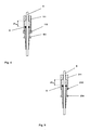
- FIG. 1 shows a stirrer unit with a reaction vessel 1 and a rod stirrer 2.
- the reaction vessel 1 has an access port 3, in which an adapter 4 of the Stabrrockers 2 is inserted accurately.
- the adapter 4 is by means of a suitable Fastener 5, such as a clamp shown here, releasably connected to the access port 3.
- the adapter 4 is designed such that it fills the access port 3 and thus closes the reaction vessel 1.
- the adapter 4 has a central passage in which a stirring shaft 6 is mounted.
- the stirring shaft 6 is connected to a stirring blade 7, which is located in the reaction vessel 1.
- the size of the stirring blade 7 can be adapted to the diameter of the reaction vessel 1.
- the stirring blade 7 can be designed to be foldable or flexible, so that it fits through the access port 3.
- the reaction vessel 1 facing away from the end of the adapter 4 is sealed by a sealing means 8 relative to the agitator shaft 6.
- the lock 10 is arranged on a guide sleeve 11, which is 29iebar against the adapter 4 along the longitudinal axis of the rod stirrer.
- the lock 10 has a bearing point 12 about which the lever-like locking can be pivoted.
- the guide sleeve 11 can be displaced with the lock 10 released along the longitudinal axis of the rod guide and fixed in several predetermined by the recesses 9 distances to the adapter 4.
- the adapter 4 and the guide sleeve 11 are made of a smooth material to allow the smoothest possible shifting, wherein the material used for the adapter 4 must be additionally chemically inert. It makes sense to produce these elements, for example made of PTFE.
- FIG. 1 engages the lock 10 in the middle recess 9 a.
- the penetration depth h could be shifted starting from this arrangement by ⁇ h along the longitudinal axis of the Stabrhakes 2, as indicated by the dashed lines shown stirring blades 7.1, 7.2.
- the guide sleeve 11 is also releasably connected via a motor flange 14 with the housing of a motor 15.
- the motor 15 has a motor shaft 16 which is connected at its free end to a second coupling element 17. Furthermore, the motor 15 has a connection 20 for a power and / or data cable.
- the second coupling element 17 engages in a first coupling element 18, which is connected to the agitator shaft 6.
- the motor 15 can transmit torque to the agitator shaft 6 via the motor shaft 16 and the coupling elements 17, 18. If the reaction vessel 1 is attached to a tripod 19 or in another suitable manner, then the reaction torque generated by the motor 15 can be transmitted via the attachment means 5 to the reaction vessel 1 and / or the stand 19. As a result, there is no need for additional securing of the rod-type stirring element 2, for example attachment of the motor 15, and it is possible to change the penetration depth h of the stirring blade 7 into the reaction vessel with one hand.
- reaction vessel 2 for example, also be part of an analytical device and be mounted in or on this.
- FIG. 2 shows the rod stirrer 2 in the disassembled state in section.
- the motor 15 can be separated together with the motor flange 14, the motor shaft 16 and the second coupling member 17 of the guide sleeve 11 by simply pulling off, since the motor flange 14 is connected via a clamping connection with the guide sleeve 11.
- the clamping connection is formed by the partially elastic, fork-like extensions or clamping springs 21 of the motor flange, which on the one hand the Enclose guide sleeve 11 and on the other hand engage with the recesses 22 in locking aids, which are externally attached to the guide sleeve (s. FIG. 3 ).
- the first coupling element 18 can be removed from the stirring shaft (not shown here).
- the guide sleeve 11 and the adapter 4 are in FIG. 2 maximally offset from each other and have a distance ⁇ h max to each other, which is defined by the distance of the recesses 9.1, 9.4.
- This maximum distance ⁇ h max corresponds to the maximum travel distance of the stirring blade and / or the stirring shaft in the reaction vessel and thus the maximum change in the penetration depth (s. FIG. 1 ).
- the stirring shaft with the stirring blade attached thereto is not shown here (s. FIG. 1 ).
- the stirring shaft can be mounted in the passages 23, 24 in the adapter 4 or in the guide sleeve 11.
- FIG. 3 the rod guide 2 is shown in a three-dimensional exploded view.
- elements here are connectable to the motor 15 power and / or data cable 24 and arranged on the outside of the guide sleeve 11 locking aids 27 are shown, which engage in the mounted state respectively in a recess 22 of the fork-like extensions 21 of the motor flange 14.
- the one-piece adapter 4 can be seen, which consists of a connecting piece 25 for connection to the reaction vessel, and an adjusting sleeve 26. Outside of the adjusting sleeve 26 a plurality of recesses 9 are mounted, which can cooperate with the lock 10.
- the coupling elements 17, 18 engage in the assembled state.
- different first coupling elements can be used, such as clamping couplings, clamping pins, threaded connections and other variants, which are well known to the person skilled in the art.
- FIG. 4 shows a further embodiment of an adapter 104 and a guide sleeve 111.
- the adapter 104 has a participatedgwinde, which cooperates with an internal thread of the guide sleeve 111.
- the threads form an adjustment thread with which the guide sleeve 111 can be displaced relative to the adapter 104 along the longitudinal axis of the rod stirring.
- the stirring shaft 6 is guided in the adapter 104 and the guide sleeve 111.
- this embodiment has a lock nut 110, which is arranged on the adapter 104.
- FIG. 5 embodiment shown has a guide sleeve 211 with an internal thread and an adapter 204 with an external thread, which cooperate threads and allow a relative displacement of the guide sleeve 211 to the adapter 204 along the longitudinal axis of the rod 2.
- a lock 210 is a screw, such as a set screw or Rädelschraube which locks the guide sleeve 210 on the adapter 204 by being screwed into the guide sleeve 210 and pressed against the adapter 104.
Landscapes
- Chemical & Material Sciences (AREA)
- Chemical Kinetics & Catalysis (AREA)
- Organic Chemistry (AREA)
- Mixers Of The Rotary Stirring Type (AREA)
- Accessories For Mixers (AREA)
- Physical Or Chemical Processes And Apparatus (AREA)
- Massaging Devices (AREA)
- Food-Manufacturing Devices (AREA)
Description
- Die Erfindung betrifft eine Rührereinheit mit einem Reaktionsgefäss und einem höhenverstellbaren Stabrührer.
- In vielen Bereichen der Chemie, Biochemie, Pharmazie und Biologie werden Stabrührer zur Durchmischung eines Reaktionsmediums in einem Reaktionsgefäss eingesetzt. Das Rühren ist zum Beispiel bei chemischen und/oder physikalischen Reaktionen mit mehreren Phasen, bei der Zugabe einer Reaktionskomponente oder bei vorhandenen Feststoffanteilen notwendig. In heterogenen OReaktionsmedien hat es die Aufgabe, die Komponenten gut zu durchmischen. In homogenen Reaktionsmedien ist Rühren häufig notwendig, um einen zugegebenen Stoff schnell und gut in der Lösung zu verteilen, um grosse lokale Konzentrationen, lokale Überhitzungen oder Siedeverzüge zu vermeiden. Soll ein Reaktionsmedium über einen längeren Zeitraum oder in einem geschlossenen Reaktionsgefäss gerührt werden, so kann zum Beispiel ein Magnetrührer oder ein klassischer KPG-Rührer verwendet werden.
- Ein Magnetrührer besteht aus einem ummantelten Eisenelement, welches in das Reaktionsmedium eingebracht wird und einem Antrieb, welcher sich ausserhalb des Reaktionsgefässes befindet. Es sind Eisenelemente mit unterschiedlichen Formen bekannt, wobei die Wahl von Form und Länge des Eisenelements auf die Dimensionen des Reaktionsgefässes und die Art und Viskosität des Reaktionsmediums abgestimmt wird. Nachteilig an diesen Rührern ist, dass das Eisenelement gerade bei komplexen Laboraufbauten nur schwer aus dem Reaktionsgefäss entfernt werden kann und ein Magnetrührer zudem nicht für viskose oder hochviskose Reaktionsmedien verwendet werden kann.
- Ein KPG-Rührer besteht häufig aus einer gläsernen Rührwelle, deren eines Ende als Rührblatt ausgestaltet oder mit einem verbunden ist und deren anderes Ende über einen Kupplung mit einem Elektromotor verbunden ist. Als Kupplung wird vor allem im Laborbereich einfach ein Stück Vakuumschlauch verwendet. KPG-Rührer können auch für die Durchmischung von Reaktionsmedien mit höheren Viskositäten verwendet werden, allerdings zeichnen sie sich aufgrund des Elektromotors durch einen hohen Platzbedarf aus und können erst ab einer bestimmten Füllhöhe des Reaktionsgefässes effektiv eingesetzt werden. Zudem müssen sowohl das Reaktionsgefäss als auch der Elektromotor an einem geeigneten Gestänge gesichert werden und gläserne Rührwellen können nur in einer Laborumgebung eingesetzt werden, da sie aufgrund der materialbedingten Bruchgefahr ständig überwacht werden sollten.
- Weiterentwicklungen haben daher häufig Rührwellen aus anderen Werkstoffen, wie verschiedenen Metallen, Keramiken oder Polymeren, welche über eine geeignete Kupplung von einem Motor angetrieben werden.
- Der Vorteil von Stabrührern, zu denen im weitesten Sinne auch die erwähnten KPG-Rührer zählen, liegt darin, dass man sie einfacher aus dem Reaktionsmedium entfernen kann, und dass sie auch hochviskose Reaktionsmedien durchmischen können.
- Die Durchmischung des Reaktionsmediums wird einerseits von der Wahl des Rührblatts, der Leistung des Motors und der eingestellten Umdrehungszahl beeinflusst, andererseits auch von der Ausrichtung des Rührblatts im Reaktionsgefäss. So hat es sich gezeigt, dass wenn sich das Volumen des Reaktionsmediums vergrössert oder der Füllstand erhöht, beispielsweise bei Zugabe weiterer Reaktanden, auch das Rührblatt nachgeführt werden sollte, um eine gleichbleibende Durchmischung zu gewährleisten. Unter Nachführung des Rührblatts wird hier sowohl eine Veränderung des Abstands zwischen einem Zugangsstutzen am Reaktionsgefäss und dem im Reaktionsgefäss angeordneten Rührblatt verstanden, als auch eine Veränderung der Eindringtiefe der Rührwelle in das Reaktionsgefäss, siehe beispiels weise in der
US 4828395,A . - In der Regel wird der Rührer mittels eines geeigneten Adapters am Zugangsstutzen des Reaktionsgefässes befestigt und das Reaktionsgefäss wie auch der Motor an einem Stativ oder ähnlichem gesichert. Um die Höhe des Rührblatts einstellen zu können, können zum Beispiel unterschiedlich lange Rührwellen und/oder Zwischenstücke eingesetzt werden. Dieses hat den Nachteil, dass zur Nachführung des Rührblatts entweder der komplette Rührer aus dem Reaktionsgefäss entfernt, demontiert und wieder zusammengebaut werden muss, oder zumindest Teile des Aufbaus oder des Rührers entfernt werden müssen.
- Daher wäre es wünschenswert, wenn die Eindringtiefe der Rührwelle einfach, schnell und reproduzierbar einstellbar wäre, um Unterbrechungen des Rührprozesses möglichst kurz zu halten. Das Reaktionsmedium sollte ständig in Bewegung bleiben, um beispielsweise lokale Überhitzungen oder unerwünschten Nebenreaktionen zu unterdrücken. Zudem könnte beim Ausbau des Rührers Reaktionsmedium aus dem Reaktionsgefäss entfernt werden, was zu einer Veränderung der Reaktanden-Verhältnisse führen kann und letztendlich einen Einfluss auf die Ausbeute und/oder die Reaktionsprodukte haben kann.
- Daher besteht die Aufgabe der Erfindung in der Entwicklung eines Stabrührers, bei dem die Eindringtiefe des Rührers in ein Reaktionsgefäss einfach und schnell verändert werden kann, ohne den Rührer aus dem Reaktionsgefäss entfernen zu müssen.
- Gelöst wird diese Aufgabe durch eine Rührereinheit mit einem Reaktionsgefäss, welches einen Zugangsstutzen aufweist, und mit einem Stabrührer. Der Stabrührer weist ein Rührblatt, eine am Rührblatt befestigte Rührwelle und einen Adapter mit einer Durchführung, in der die Rührwelle geführt ist, auf. Der Adapter kann passgenau in den Zugangsstutzen eingesetzt werden und ist mittels eines Befestigungsmittels lösbar am Zugangsstutzen befestigbar, so dass das Rührblatt und ein Teil der Rührwelle im Reaktionsgefäss angeordnet sind. Die erfindungsgemässe Rührereinheit zeichnet sich dadurch aus, dass die Eindringtiefe der Rührwelle in das Reaktionsgefäss einstellbar und mit einer Arretierung in mindestens zwei beabstandeten Positionen fixierbar ist, während der Adapter mit dem Zugangsstutzen verbunden ist.
- Eine derartige Rührereinheit ist sehr vorteilhaft, da es möglich ist, die Eindringtiefe ohne eine Demontage und/oder eine Teildemontage der Rührereinheit zu verändern und reproduzierbar in mindestens zwei Positionen einzustellen.
- Die Rührwelle ist in einer Führungshülse geführt, welche gegen den Adapter verstellbar ist. Durch eine Verschiebung der Führungshülse relativ zum Adapter entlang der Längsachse des Stabrühres wird die Rührwelle eine gewisse Strecke aus dem Reaktionsgefäss herausgezogen oder in dieses hineingeschoben, so das auf diese Weise die Eindringtiefe verändert werden kann.
- Der Abstand zwischen Adapter und Führungshülse kann beispielsweise durch Drehen, verbunden mit einer gleichzeitigen Verschiebung der Führungshülse entlang der Längsachse des Stabrührers, verändert werden, wodurch eine kontinuierliche Einstellung der Eindringtiefe ermöglicht wird.
- Dieses kann insbesondere durch eine Ausgestaltung des Adapters und der Führungshülse mit zusammenwirkenden Einstellgewinden erreicht werden. Der Adapter ist mit einem Aussengewinde ausgestaltet, welches in ein Innengewinde der Führungshülse eingreifen kann. Auf diese Weise ist eine stufenlose Verstellung der Eindringtiefe möglich.
- Zur Fixierung der gewünschten Eindringtiefe kann die Führungshülse mittels der Arretierung am Adapter festgelegt werden. Bei einer kontinuierlich verstellbaren Führungshülse kann die Arretierung beispielsweise in Form von Schrauben, Federn oder ähnlichen Elementen ausgestaltet sein, welche die Führungshülse am Adapter fixieren.
- In einer bevorzugten Ausgestaltung hat die Arretierung die Form eines Arretierhebels, welcher an der Führungshülse angeordnet ist, und welcher mit mindestens zwei voneinander beabstandete Aussparungen zusammenwirkt, welche an der Aussenseite des Adapters angeordnet sind. Ein Ende des Arretierhebels kann so ausgestaltet sein, dass dieses in die Aussparungen eingreifen und/oder einrasten kann. Zur Fixierung der Arretierung kann ein elastisches Element dienen, welches im Falle des Arretierhebels dessen eines Ende in eine der Aussparungen drückt und so darin fixiert.
- Die Ausgestaltung als Arretierhebel hat den Vorteil, dass ein Hebel einfach und insbesondere einhändig bedienbar und um eine Lagerstelle verkippbar ist. Das elastische Element kann den Arretierhebel wieder in seine ursprüngliche Position zurückstellen.
- In einer weiteren Ausgestaltung kann die Arretierung als Kontermutter ausgestaltet sein. Weiterhin kann die Arretierung als Schraube, insbesondere als Madenschraube, ausgestaltet sein. Diese beiden Ausführungen der Arretierung sind insbesondere in Kombination mit den Einstellgewinden vorteilhaft.
- Die Kontermutter kann manuell leicht gelöst werden, worauf die Eindringtiefe verändert werden kann und durch manuelles Anziehen der Kontermutter wieder fixierbar ist.
- Eine schraubenförmige Arretierung kann beispielsweise aussen aus der Führungshülse hervorstehen und dann einfach manuell gelöst oder angezogen werden. Alternativ ist es auch möglich, eine Madenschraube zu verwenden, welche mit einem geeigneten Hilfsmittel gelöst oder angezogen werden kann.
- Ein Ende der Rührwelle ist mit dem Rührblatt verbunden oder als Rührblatt ausgestaltet, das andere Ende kann mit einem ersten Kupplungselement verbunden werden oder als solches ausgestaltet sein.
- Als Antrieb kann die Rührereinheit einen Motor und eine mit diesem verbundene Motorwelle aufweisen, deren freies Ende mit einem zweiten Kupplungselement verbunden oder als solches ausgestaltet ist. Das zweite Kupplungselement kann mit dem ersten Kupplungselement gekoppelt werden, so dass zum Beispiel ein vom Motor erzeugtes Drehmoment auf die Rührwelle übertragen werden kann.
- Die Kupplungselemente sollten sich dadurch auszeichnen, dass die Kupplung schnell und ohne Einsatz von Hilfsmittel gelöst oder verbunden werden können, wobei die Ausgestaltung der Kupplungselemente nicht auf eine bestimmte Form limitiert ist, sondern jegliche bekannte Elementen umfasst, welche eine Kupplung gewährleisten können.
- Es ist vorteilhaft, wenn der Motor lösbar mit der Führungshülse verbunden werden kann, so dass dieser einfach, vorzugsweise manuell und/oder ohne Einsatz von Werkzeugen oder andere Hilfsmitteln abgetrennt werden kann, und die Rührereinheit beispielsweise an einen anderen Platz im Labor gestellt und/oder gekühlt werden kann. Um dieses zu erreichen, kann der Motor mittels eines Motorflansches mit der Führungshülse verbunden werden.
- Bevorzugt wird eine Klemmverbindung zwischen Motor und Führungshülse, die bei einer festen Verbindung zwischen Reaktionsgefäss, Adapter und Führungshülse einhändig gelöst werden kann, ohne dass die Eindringtiefe der Rührwelle verändert wird. Motor und Rührwelle können somit ohne Veränderung der Eindringtiefe von einander gelöst werden.
- Weitere Ausgestaltungen können eine Schnappverbindung, eine Einrastverbindung oder eine Bajonettverbindungen zwischen dem Motor und der Führungshülse aufweisen.
- Eine erfindungsgemässe Rührereinheit wird anhand der folgenden Figuren beschrieben, wobei gleiche Elemente mit gleichen Bezugszeichen versehen sind. Die Figuren zeigen:
- Fig. 1
- eine Rührereinheit mit einem Reaktionsgefäss und einem Stabrührer im Schnitt;
- Fig. 2
- den Stabrührer aus
Figur 1 im auseinander gebauten Zustand ohne Rührwelle und Rührblatt im Schnitt; - Fig. 3
- den Stabrührer aus
Figur 2 in einer dreidimensionalen Explosionsdarstellung; - Fig. 4
- eine weitere Ausgestaltung von Führungshülse, Adapter und Arretierung im Schnitt;
- Fig. 5
- eine weitere Ausgestaltung von Führungshülse, Adapter und Arretierung im Schnitt.
-
Figur 1 zeigt eine Rührereinheit mit einem Reaktionsgefäss 1 und einem Stabrührer 2. Das Reaktionsgefäss 1 weist einen Zugangsstutzen 3 auf, in dem ein Adapter 4 des Stabrührers 2 passgenau eingesteckt ist. Der Adapter 4 ist mittels eines geeigneten Befestigungsmittels 5, wie einer hier gezeigten Klammer, mit dem Zugangsstutzen 3 lösbar verbunden. Der Adapter 4 ist so ausgestaltet, dass er den Zugangsstutzen 3 ausfüllt und so das Reaktionsgefäss 1 verschliesst. - Der Adapter 4 hat eine mittige Durchführung, in welcher eine Rührwelle 6 gelagert ist. Die Rührwelle 6 ist mit einem Rührblatt 7 verbunden, welches sich im Reaktionsgefäss 1 befindet. Die Grösse des Rührblatts 7 kann an den Durchmesser des Reaktionsgefässes 1 angepasst werden. Zum leichteren Entfernen und Einbringen des Stabrühres in das Reaktionsgefäss 1, kann das Rührblatt 7 klappbar oder flexibel ausgestaltet sein, so dass es durch den Zugangsstutzen 3 passt. Das dem Reaktionsgefäss 1 abgewandte Ende des Adapters 4 ist durch ein Dichtmittel 8 gegenüber der Rührwelle 6 abgedichtet. Ferner befinden sich an der Aussenseite des Adapters 4 mehrere Aussparungen 9, in welche eine hebelartige Arretierung 10 einrasten kann. Die Arretierung 10 ist an einer Führungshülse 11 angeordnet, welche gegen den Adapter 4 entlang der Längsachse des Stabrührers verschiebar ist. Die Arretierung 10 weist eine Lagerstelle 12 auf, um welche die hebelartige Arretierung geschwenkt werden kann.
- Die Führungshülse 11 kann bei gelöster Arretierung 10 entlang der Längsachse des Stabrührers verschoben und in mehreren, durch die Aussparungen 9 vorgegebenen Abständen zum Adapter 4 fixiert werden. Der Adapter 4 und die Führungshülse 11 bestehen aus einem glatten Material, um ein möglichst reibungsloses Verschieben zu ermöglichen, wobei das für den Adapter 4 verwendete Material zusätzlich chemisch inert sein muss. Es bietet sich an, diese Elemente beispielsweise aus PTFE herzustellen.
- Durch Lösen der Arretierung 10, Verschieben der Führungshülse 11 und erneutes Einrasten der Arretierung 10 in eine andere Aussparung 9 kann die Eindringtiefe h des Rührblatts 7 in das Reaktionsgefäss 1 verändert werden.
- In
Figur 1 rastet die Arretierung 10 in die mittlere Aussparung 9 ein. Die Eindringtiefe h könnte ausgehend von dieser Anordnung um Δh entlang der Längsachse des Stabrühres 2 verschoben werden, wie es durch die gestrichelt eingezeichneten Rührblätter 7.1, 7.2 angedeutet wird. - Zur Fixierung der Arretierung 10 ist diese mittels eines elastischen Elements 13, welches in einer Nut der Führungshülse 11 angeordnet ist, federnd an die Führungshülse 11 angelegt. Wird Druck auf den in der Zeichnung oberen und breiter dargestellten Teil der Arretierung 10 ausgeübt, so wird diese aus einer der Vertiefungen 9 herausgedrückt, bei nachlassendem Druck durch das elastische Element 13 wieder gegen die Führungshülse 11 gedrückt und rastet in eine andere oder dieselbe Aussparung 9 ein.
- Die Führungshülse 11 ist ferner über einen Motorflansch 14 mit dem Gehäuse eines Motors 15 lösbar verbunden. Der Motor 15 weist eine Motorwelle 16 auf, welche an ihrem freien Ende mit einem zweiten Kupplungselement 17 verbunden ist. Ferner hat der Motor 15 einen Anschluss 20 für ein Strom- und/oder Datenkabel. Das zweite Kupplungselement 17 greift in ein erstes Kupplungselement 18 ein, das mit der Rührwelle 6 verbunden ist.
- Der Motor 15 kann über die Motorwelle 16 und die Kupplungselemente 17, 18 ein Drehmoment auf die Rührwelle 6 übertragen. Wenn das Reaktionsgefäss 1 an einem Stativ 19 oder in einer anderen geeigneten Weise befestigt ist, dann kann das durch den Motor 15 erzeugte Gegendrehmoment über das Befestigungsmittel 5 auf das Reaktionsgefäss 1 und/oder das Stativ 19 übertragen werden. Dadurch erübrigt sich eine zusätzliche Sicherung des Stabrühres 2, beispielsweise eine Befestigung des Motors 15, und es ist möglich, die Eindringtiefe h des Rührblatts 7 in das Reaktionsgefäss einhändig zu verändern.
- Neben der gezeigten Sicherung des Reaktionsgefässes 1 am Stativ 19, kann das Reaktionsgefäss 2 zum Beispiel auch Teil eines analytischen Geräts sein und in oder an diesem befestigt sein.
-
Figur 2 zeigt den Stabrührer 2 im auseinander gebauten Zustand im Schnitt. Der Motor 15 kann gemeinsam mit dem Motorflansch 14, der Motorwelle 16 und dem zweiten Kupplungselement 17 von der Führungshülse 11 durch einfaches Abziehen getrennt werden, da der Motorflansch 14 über eine Klemmverbindung mit der Führungshülse 11 verbunden ist. Die Klemmverbindung wird durch die teilelastischen, gabelartigen Ausläufer oder Klemmfedern 21 des Motorflansches gebildet, welche einerseits die Führungshülse 11 umschliessen und anderseits mit den Aussparungen 22 in Rasthilfen einrasten, welche aussen an der Führungshülse angebracht sind (s.Figur 3 ). - Neben dem Motor 15, kann auch das erste Kupplungselement 18 von der Rührwelle (hier nicht gezeigt) entfernt werden.
- Die Führungshülse 11 und der Adapter 4 sind in
Figur 2 maximal gegeneinander verschoben und weisen einen Abstand Δhmax zueinander auf, welcher durch den Abstand der Aussparungen 9.1, 9.4 definiert wird. Dieser maximale Abstand Δhmax entspricht der maximalen Verfahrstrecke des Rührblatts und/oder der Rührwelle im Reaktionsgefäss und damit der maximalen Änderung der Eindringtiefe (s.Figur 1 ). - Die Rührwelle mit dem daran befestigtem Rührblatt ist hier nicht dargestellt (s.
Figur 1 ). Die Rührwelle kann in den Durchführungen 23, 24 im Adapter 4 bzw. in der Führungshülse 11 gelagert werden. - In
Figur 3 ist der Stabrührer 2 in einer dreidimensionalen Explosionsdarstellung gezeigt. Zusätzlich zu den bereits in denFiguren 1 und2 gezeigten Elementen sind hier ein mit dem Motor 15 verbindbares Strom- und/oder Datenkabel 24 sowie die an der Aussenseite der Führungshülse 11 angeordneten Rasthilfen 27 gezeigt, welche im montierten Zustand jeweils in eine Aussparung 22 der gabelartigen Ausläufer 21 des Motorflansches 14 einrasten. - Weiterhin ist der einstückige Adapter 4 zu erkennen, welcher aus einem Verbindungsstück 25 zur Verbindung mit dem Reaktionsgefäss, sowie einer Verstellhülse 26 besteht. Aussen an der Verstellhülse 26 sind mehrere Aussparungen 9 angebracht, welche mit der Arretierung 10 zusammenwirken können.
- Die Kupplungselemente 17, 18 greifen im montierten Zustand ineinander. In Abhängigkeit des Materials der verwendeten Rührwelle können unterschiedliche erste Kupplungselemente eingesetzt werden, wie beispielsweise Klemmkupplungen, Spannzapfen, Gewindeverbindungen und andere Varianten, welche dem Fachmann wohlbekannt sind.
-
Figur 4 zeigt eine weitere Ausgestaltung eines Adapters 104 und einer Führungshülse 111. Der Adapter 104 weist ein Aussengwinde auf, welches mit einem Innengewinde der Führungshülse 111 zusammenwirkt. Die Gewinde bilden ein Einstellgewinde mit dem die Führungshülse 111 relativ zum Adapter 104 entlang der Längsachse des Stabrühres verschoben werden kann. Die Rührwelle 6 wird im Adapter 104 und der Führungshülse 111 geführt. Als Arretierung 110 weist diese Ausgestaltung eine Kontermutter 110 auf, welche am Adapter 104 angeordnet ist. - Das in
Figur 5 gezeigte Ausführungsbeispiel weist eine Führungshülse 211 mit einem Innengewinde und einen Adapter 204 mit einem Aussengewinde auf, welche Gewinde zusammenwirken und eine relative Verschiebung der Führungshülse 211 zum Adapter 204 entlang der Längsachse des Stabrühres 2 erlauben. Als Arretierung 210 dient eine Schraube, beispielsweise eine Madenschraube oder Rädelschraube, welche die Führungshülse 210 am Adapter 204 arretiert, indem diese in die Führungshülse 210 geschraubt und gegen den Adapter 104 gedrückt wird. -
- 1
- Reaktionsgefäss
- 2
- Stabrührer
- 3
- Zugangsstutzen
- 4,104,204
- Adapter
- 5
- Befestigungsmittel
- 6
- Rührwelle
- 7,7.1,7.2
- Rührblatt
- 8
- Dichtmittel
- 9,9.1,9.4
- Aussparung
- 10, 110, 210
- Arretierung
- 11,111,211
- Führungshülse
- 12
- Lagerstelle
- 13
- elastisches Element
- 14
- Motorflansch
- 15
- Motor
- 16
- Motorwelle
- 17
- zweite Kupplungselement
- 18
- erstes Kupplungselement
- 19
- Stativ
- 20
- Anschluss
- 21
- gabelartige Ausläufer / Klemmfedern
- 22
- Aussparung
- 23
- Durchführung in 4
- 24
- Strom- und/oder Datenkabel
- 25
- Verbindungsstück
- 26
- Verstellhülse
- 27
- Rasthilfe
- 28
- Durchführung in 11
Claims (11)
- Rührereinheit mit einem Reaktionsgefäss (1), welches einen Zugangsstutzen (3) aufweist, und mit einem Stabrührer (2), welcher ein Rührblatt (7), eine am Rührblatt befestigte Rührwelle (6) und einen Adapter (4,104, 204) mit einer Durchführung (23), in der die Rührwelle geführt ist, aufweist, wobei der Adapter (4,104,204) in den Zugangsstutzen (3) einsetzbar und mittels eines Befestigungsmittels (5) lösbar am Zugangsstutzen (3) befestigt ist, so dass das Rührblatt (7) und ein Teil der Rührwelle (6) im Reaktionsgefäss (1) angeordnet sind, dadurch gekennzeichnet, dass die Eindringtiefe (h) der Rührwelle (6) ins Reaktionsgefäss (1) einstellbar und mit einer Arretierung (10, 110, 210) in mindestens zwei beabstandeten Positionen fixierbar ist, während der Adapter (4, 104, 204) mit dem Zugangsstutzen (3) verbunden ist.
- Rührereinheit nach Anspruch 1, dadurch gekennzeichnet, dass die Rührwelle in einer Führungshülse (11) geführt ist, wobei der Adapter (4, 104, 204) und die Führungshülse (11, 111, 211) entlang der Längsachse des Stabrührers (2) gegeneinander verstellbar sind.
- Rührereinheit nach Anspruch 2, dadurch gekennzeichnet, dass die Führungshülse (11, 111, 211) mittels der Arretierung (10, 110, 210) am Adapter (4, 104, 204) festlegbar ist.
- Rührereinheit nach einem der Ansprüche 1 bis 3, dadurch gekennzeichnet, dass die Arretierung (10) als Arretierhebel ausgestaltet und an der Führungshülse (11) angeordnet ist.
- Rührereinheit nach einem der Ansprüche 1 bis 4, dadurch gekennzeichnet, dass die Arretierung (10) mit einem elastischen Element (13) fixierbar ist.
- Rührereinheit nach einem der Ansprüche 1 bis 5, dadurch gekennzeichnet, dass an der Aussenseite des Adapters (4) mindestens zwei beabstandete Aussparungen (9, 9.1, 9.2) angeordnet sind, welche mit der Arretierung (10) zusammenwirken.
- Rührereinheit nach einem der Ansprüche 1 bis 3, dadurch gekennzeichnet, dass der Adapter (104, 204) ein Aussengewinde und die Führungshülse (111, 211) ein Innengewinde aufweisen, wobei die Gewinde zusammenwirken und die Eindringtiefe (h) stufenlos einstellbar ist.
- Rührereinheit nach Anspruch 7, dadurch gekennzeichnet, dass die Arretierung (110, 210) als Kontermutter oder schraubenförmig ausgestaltet ist.
- Rührereinheit nach einem der Ansprüche 1 bis 8, dadurch gekennzeichnet, dass das dem Rührblatt (7) gegenüberliegende Ende der Rührwelle (6) mit einem ersten Kupplungselement (18) verbunden ist.
- Rührereinheit nach einem der Ansprüche 1 bis 9, dadurch gekennzeichnet, dass diese ferner einen Motor (15) und eine mit dem Motor (15) verbundene Motorwelle (16) aufweist, wobei das freie Ende der Motorwelle (16) mit einem zweiten Kupplungselement (17) verbunden ist, welches mit dem ersten Kupplungselement (18) koppelbar ist.
- Rührereinheit nach Anspruch 10, dadurch gekennzeichnet, dass der Motor (15) mittels eines Motorflansches (14) lösbar mit der Führungshülse (11, 111, 211) verbunden ist.
Priority Applications (6)
| Application Number | Priority Date | Filing Date | Title |
|---|---|---|---|
| EP07119828A EP2055372B1 (de) | 2007-11-01 | 2007-11-01 | Rührereinheit aufweisend einen Adapter |
| AT07119828T ATE481162T1 (de) | 2007-11-01 | 2007-11-01 | Rührereinheit aufweisend einen adapter |
| DE502007005070T DE502007005070D1 (de) | 2007-11-01 | 2007-11-01 | Rührereinheit aufweisend einen Adapter |
| US12/240,052 US8337074B2 (en) | 2007-11-01 | 2008-09-29 | Stirrer unit |
| JP2008262754A JP5314377B2 (ja) | 2007-11-01 | 2008-10-09 | 撹拌機ユニット |
| CN200810175164.2A CN101422710B (zh) | 2007-11-01 | 2008-10-30 | 搅拌器单元 |
Applications Claiming Priority (1)
| Application Number | Priority Date | Filing Date | Title |
|---|---|---|---|
| EP07119828A EP2055372B1 (de) | 2007-11-01 | 2007-11-01 | Rührereinheit aufweisend einen Adapter |
Publications (2)
| Publication Number | Publication Date |
|---|---|
| EP2055372A1 EP2055372A1 (de) | 2009-05-06 |
| EP2055372B1 true EP2055372B1 (de) | 2010-09-15 |
Family
ID=39186088
Family Applications (1)
| Application Number | Title | Priority Date | Filing Date |
|---|---|---|---|
| EP07119828A Not-in-force EP2055372B1 (de) | 2007-11-01 | 2007-11-01 | Rührereinheit aufweisend einen Adapter |
Country Status (6)
| Country | Link |
|---|---|
| US (1) | US8337074B2 (de) |
| EP (1) | EP2055372B1 (de) |
| JP (1) | JP5314377B2 (de) |
| CN (1) | CN101422710B (de) |
| AT (1) | ATE481162T1 (de) |
| DE (1) | DE502007005070D1 (de) |
Families Citing this family (24)
| Publication number | Priority date | Publication date | Assignee | Title |
|---|---|---|---|---|
| JP2011230091A (ja) * | 2010-04-30 | 2011-11-17 | Hitachi Koki Co Ltd | 電動工具及び攪拌機 |
| FR2960863B1 (fr) * | 2010-06-07 | 2012-07-13 | Fillon Technologies | Couvercle de fermeture pour recipient equipe d'un joint d'etancheite |
| JP5748992B2 (ja) * | 2010-12-03 | 2015-07-15 | フンボ テック カンパニー リミティドHEUNGBO TECH Co., Ltd. | 均質混練機 |
| EP3922712A3 (de) * | 2011-10-25 | 2022-03-09 | Life Technologies Corporation | Fluidmischsysteme mit einem einstellbaren mischelement |
| WO2013130576A1 (en) | 2012-02-28 | 2013-09-06 | Purpod Holdings, Llc | A nutracuetical compounding system and method therefore |
| CN104741208B (zh) * | 2013-12-30 | 2017-02-15 | 石嘴山市迎圣工贸有限公司 | 一种新型搅拌装置 |
| WO2015142959A1 (en) | 2014-03-17 | 2015-09-24 | Sani-Tech West, Inc. | Magnetic mixing system and method |
| US8960999B1 (en) * | 2014-03-28 | 2015-02-24 | Gudpod Holdings, Llc | System for mixing beverages and method of doing the same |
| DE102014113986A1 (de) | 2014-09-26 | 2016-03-31 | Krones Ag | Vorrichtung und Verfahren zum Befüllen von Behältern mit einem Füllprodukt |
| WO2016061526A1 (en) | 2014-10-17 | 2016-04-21 | Sani-Tech West, Inc. | Mixing and filtering system and method |
| CN104437296B (zh) * | 2014-11-06 | 2016-11-23 | 上海远怀化工科技有限公司 | 一种高硼硅玻璃反应釜密封件 |
| DE102014116705B4 (de) * | 2014-11-14 | 2025-07-24 | Hans Heidolph GmbH | Laborrührer |
| US10781112B2 (en) * | 2015-05-18 | 2020-09-22 | Sunrui Marine Environment Engineering Co., Ltd. | Dehydrogenation tank and ballast water treatment system having the same |
| DE102015113822A1 (de) * | 2015-08-20 | 2017-02-23 | Gako International Gmbh | Apotheken-Rezepturherstellungs-Kruken-Deckel, Apotheken-Rezepturherstellungs-Kruken-Boden, Apotheken-Rezepturherstellungs-Kruken-Adapter, Apotheken-Rezepturherstellungs-Kruke damit, Apotheken-Rezepturherstellungs-Vorrichtungs-Hubarm sowie Apotheken-Rezepturherstellungs-Vorrichtung damit |
| DK3372674T3 (da) * | 2015-11-02 | 2020-10-12 | Megakaryon Corp | Fremgangsmåde til fremstilling af blodplader under anvendelse af røreindretning med frem- og tilbagegående rørebevægelse |
| BE1024191B1 (nl) * | 2016-04-28 | 2017-12-14 | Soudal | Vochtgevoelige producten volgens een verbeterde werkwijze |
| USD843162S1 (en) | 2016-09-15 | 2019-03-19 | Gudpod Corp. | Pod for a beverage mixing system |
| US20190343339A1 (en) * | 2016-11-21 | 2019-11-14 | Techno System Co., Ltd. | Soup supply apparatus |
| CN108435017A (zh) * | 2018-04-28 | 2018-08-24 | 慈溪市启承机械科技有限公司 | 一种建筑工程防水施工方法 |
| CN108714385A (zh) * | 2018-05-28 | 2018-10-30 | 芜湖纵横智能制造产业技术研究有限公司 | 一种畜牧养殖用便于更换和维修的搅拌装置 |
| CN109224953B (zh) * | 2018-10-18 | 2021-11-16 | 宁化宽信科技服务有限公司 | 一种教学用化学实验搅拌装置 |
| CN112169741B (zh) * | 2020-11-16 | 2022-03-22 | 杭州重力脚轮科技有限公司 | 聚氨酯搅拌反应釜 |
| CN114432942B (zh) * | 2021-12-28 | 2024-11-15 | 浙江伟博化工科技有限公司 | 邻苯二甲酸二异壬酯复合增塑剂制备装置及其制备方法 |
| CN119186468B (zh) * | 2024-11-27 | 2025-04-18 | 阳泉晋天朗洁环保科技有限公司 | 一种消毒液生产反应装置 |
Family Cites Families (28)
| Publication number | Priority date | Publication date | Assignee | Title |
|---|---|---|---|---|
| US1447653A (en) * | 1922-03-29 | 1923-03-06 | John R Fish | Agitator |
| US2191739A (en) * | 1937-10-23 | 1940-02-27 | American Cyanamid Co | Agitating, aerating, and/or mixing machine |
| US3622129A (en) * | 1969-05-14 | 1971-11-23 | Bellco Glass Inc | Magnetic stirrer apparatus |
| US3656974A (en) * | 1969-11-28 | 1972-04-18 | Richard F Mihalyi | Power driven stirrer |
| JPS5343986B2 (de) * | 1974-02-01 | 1978-11-24 | ||
| DE2700818A1 (de) * | 1977-01-11 | 1978-07-13 | Dieter Kupka | Ruehrwerk mit hubwerk fuer laeuterbottiche |
| DE2757486A1 (de) * | 1977-12-22 | 1979-07-05 | Draiswerke Gmbh | Vorrichtung zum diskontinuierlichen mischen von mindestens zwei stoffen |
| US4225247A (en) * | 1979-03-09 | 1980-09-30 | Harry Hodson | Mixing and agitating device |
| FR2476307A1 (fr) * | 1980-02-19 | 1981-08-21 | Sablons Fonderies Atel | Dispositif de reperage de niveau |
| US4422770A (en) * | 1982-01-20 | 1983-12-27 | Geible Harry F | Paint stirrer |
| JPS59162934A (ja) * | 1983-03-09 | 1984-09-13 | Hitachi Ltd | 撹拌翼の取付位置可変装置 |
| US4512666A (en) * | 1984-02-24 | 1985-04-23 | Corning Glass Works | Adjustable height magnetic stirrer |
| US4828395A (en) * | 1985-02-21 | 1989-05-09 | Yamato Scientific Company, Limited | Continuous flow type homogenizer |
| DK104985A (da) * | 1985-03-07 | 1985-06-21 | Ok Lica Aps | Blandeapparat med roterende blandeorgan |
| US4832501A (en) * | 1988-04-20 | 1989-05-23 | Mccauley Gayle A | Stove top stirrer |
| US5251979A (en) * | 1992-07-24 | 1993-10-12 | Larsen Paul R | Paint can cover with mixer |
| US5533805A (en) * | 1995-04-27 | 1996-07-09 | Mandel; Saralynn | Free-standing stirrer appliance |
| GB2313557B (en) * | 1996-05-30 | 1998-04-22 | Fasih Uddin Khalid | Food mixers |
| DE29713578U1 (de) * | 1997-04-05 | 1997-09-25 | Konietzko, Albrecht, 96049 Bamberg | Schraubkruke als Abgabegefäß für mit einem Rührwerk herstellbare pharmazeutische und/oder kosmetische Salben o.dgl. |
| US6341887B1 (en) * | 1998-12-18 | 2002-01-29 | Marienlyst Eiendom As | Ice cream mixing apparatus with a washing function having an auger with a vane wheel |
| US6076958A (en) * | 1999-03-30 | 2000-06-20 | Proquip, Inc. | Impeller with folding blade and method for using the same |
| US6113258A (en) * | 1999-06-29 | 2000-09-05 | Ardent; John Craig | Battery powered food stirrer with pivotally mounted spring biased arms |
| US7407631B2 (en) * | 2004-04-22 | 2008-08-05 | Varian, Inc. | Apparatus and method for agitating a sample during in vitro testing |
| CN2712448Y (zh) * | 2004-07-07 | 2005-07-27 | 杜原 | 搅拌头 |
| US7682067B2 (en) * | 2005-04-22 | 2010-03-23 | Hyclone Laboratories, Inc. | Mixing systems and related mixers |
| NL1034240C2 (nl) * | 2007-08-08 | 2009-02-10 | Foremost Bv | Melkopschuimer. |
| US20110235463A1 (en) * | 2010-03-29 | 2011-09-29 | Domino's Pizza Pmc, Inc. | Mixing apparatus |
| US8398298B2 (en) * | 2010-12-14 | 2013-03-19 | William H. Swader | Automatic pot stirrer |
-
2007
- 2007-11-01 EP EP07119828A patent/EP2055372B1/de not_active Not-in-force
- 2007-11-01 AT AT07119828T patent/ATE481162T1/de active
- 2007-11-01 DE DE502007005070T patent/DE502007005070D1/de active Active
-
2008
- 2008-09-29 US US12/240,052 patent/US8337074B2/en not_active Expired - Fee Related
- 2008-10-09 JP JP2008262754A patent/JP5314377B2/ja not_active Expired - Fee Related
- 2008-10-30 CN CN200810175164.2A patent/CN101422710B/zh not_active Expired - Fee Related
Also Published As
| Publication number | Publication date |
|---|---|
| JP2009113032A (ja) | 2009-05-28 |
| US20090116335A1 (en) | 2009-05-07 |
| DE502007005070D1 (de) | 2010-10-28 |
| US8337074B2 (en) | 2012-12-25 |
| ATE481162T1 (de) | 2010-10-15 |
| EP2055372A1 (de) | 2009-05-06 |
| JP5314377B2 (ja) | 2013-10-16 |
| CN101422710A (zh) | 2009-05-06 |
| CN101422710B (zh) | 2014-01-01 |
Similar Documents
| Publication | Publication Date | Title |
|---|---|---|
| EP2055372A1 (de) | Rührereinheit aufweisend einen Adapter | |
| DE60007256T2 (de) | Querverbindung für die Wirbelsäule | |
| EP3433353B1 (de) | Anlage für biotechnologische anwendungen mit träger zur lagerung von komponenten | |
| WO2003066203A1 (de) | Dispergier-vorrichtung | |
| EP0379834A1 (de) | Kupplungsvorrichtung, insbesondere an Apparaten zum Dispergieren | |
| DE2719317A1 (de) | Vorrichtung und verfahren zur herstellung eines elutionsmittels fuer die fluessigchromatographie | |
| EP2140931B9 (de) | Rührmaschine mit längsverstellbarer Werkzeugaufnahme | |
| DE102006020813B3 (de) | Behälteranordnung mit einem Behälter mit flexibler Wandung | |
| EP2916764B1 (de) | Instrumentenhalter zum befestigen eines medizinischen instrumentes an einem gelenkarm | |
| EP0657217A1 (de) | Laborgerät mit einer Aufnahme für einen Stativstab | |
| WO2020084040A1 (de) | Schüttel- und/oder mischgerät | |
| DE102007035641B3 (de) | Übertragungssystem | |
| EP3202490B1 (de) | Rühranordnung | |
| EP1459780B1 (de) | Platziervorrichtung für einen Katheter | |
| EP3231380B1 (de) | Werkzeug für ein medizinisches instrument und medizinisches instrument | |
| EP4279182B1 (de) | Pipette für den gebrauch mit einer pipettenspitze | |
| DE202007005400U1 (de) | Behälteranordnung mit einem Behälter mit flexibler Wandung | |
| DE10342304B4 (de) | Rüssel zur Entnahme und/oder Zufuhr einer Flüssigkeit | |
| WO2000048721A1 (de) | Zusammensteckbares rührwerkzeug für ein behältnis | |
| EP3538271B1 (de) | Handdosiervorrichtung | |
| AT412244B (de) | Objekttisch | |
| DE202022101215U1 (de) | Rührstab | |
| DE102022115955A1 (de) | Dosierpumpe mit Hubeinstellung | |
| WO2017186257A1 (de) | Mischvorrichtung | |
| WO2024083498A2 (de) | Modulares laborgerät |
Legal Events
| Date | Code | Title | Description |
|---|---|---|---|
| PUAI | Public reference made under article 153(3) epc to a published international application that has entered the european phase |
Free format text: ORIGINAL CODE: 0009012 |
|
| AK | Designated contracting states |
Kind code of ref document: A1 Designated state(s): AT BE BG CH CY CZ DE DK EE ES FI FR GB GR HU IE IS IT LI LT LU LV MC MT NL PL PT RO SE SI SK TR |
|
| AX | Request for extension of the european patent |
Extension state: AL BA HR MK RS |
|
| 17P | Request for examination filed |
Effective date: 20091028 |
|
| AKX | Designation fees paid |
Designated state(s): AT BE BG CH CY CZ DE DK EE ES FI FR GB GR HU IE IS IT LI LT LU LV MC MT NL PL PT RO SE SI SK TR |
|
| GRAP | Despatch of communication of intention to grant a patent |
Free format text: ORIGINAL CODE: EPIDOSNIGR1 |
|
| GRAS | Grant fee paid |
Free format text: ORIGINAL CODE: EPIDOSNIGR3 |
|
| GRAA | (expected) grant |
Free format text: ORIGINAL CODE: 0009210 |
|
| AK | Designated contracting states |
Kind code of ref document: B1 Designated state(s): AT BE BG CH CY CZ DE DK EE ES FI FR GB GR HU IE IS IT LI LT LU LV MC MT NL PL PT RO SE SI SK TR |
|
| REG | Reference to a national code |
Ref country code: GB Ref legal event code: FG4D Free format text: NOT ENGLISH Ref country code: CH Ref legal event code: EP |
|
| REG | Reference to a national code |
Ref country code: IE Ref legal event code: FG4D Free format text: LANGUAGE OF EP DOCUMENT: GERMAN |
|
| REF | Corresponds to: |
Ref document number: 502007005070 Country of ref document: DE Date of ref document: 20101028 Kind code of ref document: P |
|
| REG | Reference to a national code |
Ref country code: SE Ref legal event code: TRGR |
|
| REG | Reference to a national code |
Ref country code: NL Ref legal event code: T3 |
|
| PG25 | Lapsed in a contracting state [announced via postgrant information from national office to epo] |
Ref country code: LT Free format text: LAPSE BECAUSE OF FAILURE TO SUBMIT A TRANSLATION OF THE DESCRIPTION OR TO PAY THE FEE WITHIN THE PRESCRIBED TIME-LIMIT Effective date: 20100915 Ref country code: FI Free format text: LAPSE BECAUSE OF FAILURE TO SUBMIT A TRANSLATION OF THE DESCRIPTION OR TO PAY THE FEE WITHIN THE PRESCRIBED TIME-LIMIT Effective date: 20100915 |
|
| LTIE | Lt: invalidation of european patent or patent extension |
Effective date: 20100915 |
|
| PG25 | Lapsed in a contracting state [announced via postgrant information from national office to epo] |
Ref country code: PL Free format text: LAPSE BECAUSE OF FAILURE TO SUBMIT A TRANSLATION OF THE DESCRIPTION OR TO PAY THE FEE WITHIN THE PRESCRIBED TIME-LIMIT Effective date: 20100915 Ref country code: SI Free format text: LAPSE BECAUSE OF FAILURE TO SUBMIT A TRANSLATION OF THE DESCRIPTION OR TO PAY THE FEE WITHIN THE PRESCRIBED TIME-LIMIT Effective date: 20100915 Ref country code: CY Free format text: LAPSE BECAUSE OF FAILURE TO SUBMIT A TRANSLATION OF THE DESCRIPTION OR TO PAY THE FEE WITHIN THE PRESCRIBED TIME-LIMIT Effective date: 20100915 |
|
| PG25 | Lapsed in a contracting state [announced via postgrant information from national office to epo] |
Ref country code: LV Free format text: LAPSE BECAUSE OF FAILURE TO SUBMIT A TRANSLATION OF THE DESCRIPTION OR TO PAY THE FEE WITHIN THE PRESCRIBED TIME-LIMIT Effective date: 20100915 Ref country code: GR Free format text: LAPSE BECAUSE OF FAILURE TO SUBMIT A TRANSLATION OF THE DESCRIPTION OR TO PAY THE FEE WITHIN THE PRESCRIBED TIME-LIMIT Effective date: 20101216 |
|
| REG | Reference to a national code |
Ref country code: IE Ref legal event code: FD4D |
|
| PG25 | Lapsed in a contracting state [announced via postgrant information from national office to epo] |
Ref country code: IE Free format text: LAPSE BECAUSE OF FAILURE TO SUBMIT A TRANSLATION OF THE DESCRIPTION OR TO PAY THE FEE WITHIN THE PRESCRIBED TIME-LIMIT Effective date: 20100915 |
|
| PG25 | Lapsed in a contracting state [announced via postgrant information from national office to epo] |
Ref country code: RO Free format text: LAPSE BECAUSE OF FAILURE TO SUBMIT A TRANSLATION OF THE DESCRIPTION OR TO PAY THE FEE WITHIN THE PRESCRIBED TIME-LIMIT Effective date: 20100915 Ref country code: SK Free format text: LAPSE BECAUSE OF FAILURE TO SUBMIT A TRANSLATION OF THE DESCRIPTION OR TO PAY THE FEE WITHIN THE PRESCRIBED TIME-LIMIT Effective date: 20100915 Ref country code: CZ Free format text: LAPSE BECAUSE OF FAILURE TO SUBMIT A TRANSLATION OF THE DESCRIPTION OR TO PAY THE FEE WITHIN THE PRESCRIBED TIME-LIMIT Effective date: 20100915 Ref country code: IS Free format text: LAPSE BECAUSE OF FAILURE TO SUBMIT A TRANSLATION OF THE DESCRIPTION OR TO PAY THE FEE WITHIN THE PRESCRIBED TIME-LIMIT Effective date: 20110115 Ref country code: PT Free format text: LAPSE BECAUSE OF FAILURE TO SUBMIT A TRANSLATION OF THE DESCRIPTION OR TO PAY THE FEE WITHIN THE PRESCRIBED TIME-LIMIT Effective date: 20110117 Ref country code: IT Free format text: LAPSE BECAUSE OF FAILURE TO SUBMIT A TRANSLATION OF THE DESCRIPTION OR TO PAY THE FEE WITHIN THE PRESCRIBED TIME-LIMIT Effective date: 20100915 Ref country code: EE Free format text: LAPSE BECAUSE OF FAILURE TO SUBMIT A TRANSLATION OF THE DESCRIPTION OR TO PAY THE FEE WITHIN THE PRESCRIBED TIME-LIMIT Effective date: 20100915 |
|
| PG25 | Lapsed in a contracting state [announced via postgrant information from national office to epo] |
Ref country code: MC Free format text: LAPSE BECAUSE OF NON-PAYMENT OF DUE FEES Effective date: 20101130 Ref country code: ES Free format text: LAPSE BECAUSE OF FAILURE TO SUBMIT A TRANSLATION OF THE DESCRIPTION OR TO PAY THE FEE WITHIN THE PRESCRIBED TIME-LIMIT Effective date: 20101226 |
|
| PLBE | No opposition filed within time limit |
Free format text: ORIGINAL CODE: 0009261 |
|
| STAA | Information on the status of an ep patent application or granted ep patent |
Free format text: STATUS: NO OPPOSITION FILED WITHIN TIME LIMIT |
|
| REG | Reference to a national code |
Ref country code: FR Ref legal event code: ST Effective date: 20110801 |
|
| 26N | No opposition filed |
Effective date: 20110616 |
|
| PG25 | Lapsed in a contracting state [announced via postgrant information from national office to epo] |
Ref country code: DK Free format text: LAPSE BECAUSE OF FAILURE TO SUBMIT A TRANSLATION OF THE DESCRIPTION OR TO PAY THE FEE WITHIN THE PRESCRIBED TIME-LIMIT Effective date: 20100915 |
|
| REG | Reference to a national code |
Ref country code: DE Ref legal event code: R097 Ref document number: 502007005070 Country of ref document: DE Effective date: 20110616 |
|
| PG25 | Lapsed in a contracting state [announced via postgrant information from national office to epo] |
Ref country code: FR Free format text: LAPSE BECAUSE OF NON-PAYMENT OF DUE FEES Effective date: 20101130 |
|
| PG25 | Lapsed in a contracting state [announced via postgrant information from national office to epo] |
Ref country code: MT Free format text: LAPSE BECAUSE OF FAILURE TO SUBMIT A TRANSLATION OF THE DESCRIPTION OR TO PAY THE FEE WITHIN THE PRESCRIBED TIME-LIMIT Effective date: 20100915 |
|
| PG25 | Lapsed in a contracting state [announced via postgrant information from national office to epo] |
Ref country code: LU Free format text: LAPSE BECAUSE OF NON-PAYMENT OF DUE FEES Effective date: 20101101 Ref country code: BG Free format text: LAPSE BECAUSE OF FAILURE TO SUBMIT A TRANSLATION OF THE DESCRIPTION OR TO PAY THE FEE WITHIN THE PRESCRIBED TIME-LIMIT Effective date: 20100915 Ref country code: HU Free format text: LAPSE BECAUSE OF FAILURE TO SUBMIT A TRANSLATION OF THE DESCRIPTION OR TO PAY THE FEE WITHIN THE PRESCRIBED TIME-LIMIT Effective date: 20110316 |
|
| PG25 | Lapsed in a contracting state [announced via postgrant information from national office to epo] |
Ref country code: TR Free format text: LAPSE BECAUSE OF FAILURE TO SUBMIT A TRANSLATION OF THE DESCRIPTION OR TO PAY THE FEE WITHIN THE PRESCRIBED TIME-LIMIT Effective date: 20100915 |
|
| PG25 | Lapsed in a contracting state [announced via postgrant information from national office to epo] |
Ref country code: BG Free format text: LAPSE BECAUSE OF FAILURE TO SUBMIT A TRANSLATION OF THE DESCRIPTION OR TO PAY THE FEE WITHIN THE PRESCRIBED TIME-LIMIT Effective date: 20101215 |
|
| REG | Reference to a national code |
Ref country code: CH Ref legal event code: PCOW Free format text: NEW ADDRESS: IM LANGACHER 44, 8606 GREIFENSEE (CH) |
|
| REG | Reference to a national code |
Ref country code: AT Ref legal event code: MM01 Ref document number: 481162 Country of ref document: AT Kind code of ref document: T Effective date: 20121130 |
|
| PG25 | Lapsed in a contracting state [announced via postgrant information from national office to epo] |
Ref country code: AT Free format text: LAPSE BECAUSE OF NON-PAYMENT OF DUE FEES Effective date: 20121130 |
|
| PGFP | Annual fee paid to national office [announced via postgrant information from national office to epo] |
Ref country code: SE Payment date: 20141107 Year of fee payment: 8 |
|
| PGFP | Annual fee paid to national office [announced via postgrant information from national office to epo] |
Ref country code: NL Payment date: 20141111 Year of fee payment: 8 |
|
| PGFP | Annual fee paid to national office [announced via postgrant information from national office to epo] |
Ref country code: BE Payment date: 20141120 Year of fee payment: 8 |
|
| REG | Reference to a national code |
Ref country code: CH Ref legal event code: PFA Owner name: METTLER-TOLEDO GMBH, CH Free format text: FORMER OWNER: METTLER-TOLEDO AG, CH |
|
| PGFP | Annual fee paid to national office [announced via postgrant information from national office to epo] |
Ref country code: GB Payment date: 20151027 Year of fee payment: 9 Ref country code: DE Payment date: 20151130 Year of fee payment: 9 Ref country code: CH Payment date: 20151026 Year of fee payment: 9 |
|
| REG | Reference to a national code |
Ref country code: NL Ref legal event code: MM Effective date: 20151201 |
|
| PG25 | Lapsed in a contracting state [announced via postgrant information from national office to epo] |
Ref country code: SE Free format text: LAPSE BECAUSE OF NON-PAYMENT OF DUE FEES Effective date: 20151102 |
|
| PG25 | Lapsed in a contracting state [announced via postgrant information from national office to epo] |
Ref country code: NL Free format text: LAPSE BECAUSE OF NON-PAYMENT OF DUE FEES Effective date: 20151201 |
|
| REG | Reference to a national code |
Ref country code: DE Ref legal event code: R119 Ref document number: 502007005070 Country of ref document: DE |
|
| REG | Reference to a national code |
Ref country code: CH Ref legal event code: PL |
|
| GBPC | Gb: european patent ceased through non-payment of renewal fee |
Effective date: 20161101 |
|
| PG25 | Lapsed in a contracting state [announced via postgrant information from national office to epo] |
Ref country code: CH Free format text: LAPSE BECAUSE OF NON-PAYMENT OF DUE FEES Effective date: 20161130 Ref country code: LI Free format text: LAPSE BECAUSE OF NON-PAYMENT OF DUE FEES Effective date: 20161130 Ref country code: BE Free format text: LAPSE BECAUSE OF NON-PAYMENT OF DUE FEES Effective date: 20151130 |
|
| PG25 | Lapsed in a contracting state [announced via postgrant information from national office to epo] |
Ref country code: DE Free format text: LAPSE BECAUSE OF NON-PAYMENT OF DUE FEES Effective date: 20170601 Ref country code: GB Free format text: LAPSE BECAUSE OF NON-PAYMENT OF DUE FEES Effective date: 20161101 |