EP2054649B1 - Absperrarmatur - Google Patents
Absperrarmatur Download PDFInfo
- Publication number
- EP2054649B1 EP2054649B1 EP20070785550 EP07785550A EP2054649B1 EP 2054649 B1 EP2054649 B1 EP 2054649B1 EP 20070785550 EP20070785550 EP 20070785550 EP 07785550 A EP07785550 A EP 07785550A EP 2054649 B1 EP2054649 B1 EP 2054649B1
- Authority
- EP
- European Patent Office
- Prior art keywords
- shut
- sealing
- housing
- sealing body
- ribs
- Prior art date
- Legal status (The legal status is an assumption and is not a legal conclusion. Google has not performed a legal analysis and makes no representation as to the accuracy of the status listed.)
- Active
Links
- 238000007789 sealing Methods 0.000 claims description 21
- 238000006073 displacement reaction Methods 0.000 claims 1
- 239000000725 suspension Substances 0.000 description 3
- 239000004698 Polyethylene Substances 0.000 description 2
- 230000006835 compression Effects 0.000 description 2
- 238000007906 compression Methods 0.000 description 2
- 230000000694 effects Effects 0.000 description 2
- 239000002184 metal Substances 0.000 description 2
- 239000012815 thermoplastic material Substances 0.000 description 2
- 238000004140 cleaning Methods 0.000 description 1
- 238000003780 insertion Methods 0.000 description 1
- 230000037431 insertion Effects 0.000 description 1
- 239000004033 plastic Substances 0.000 description 1
- 229920003023 plastic Polymers 0.000 description 1
- -1 polyethylene Polymers 0.000 description 1
- 229920000573 polyethylene Polymers 0.000 description 1
- 238000009417 prefabrication Methods 0.000 description 1
- 230000003068 static effect Effects 0.000 description 1
- 238000003466 welding Methods 0.000 description 1
Images


Classifications
-
- F—MECHANICAL ENGINEERING; LIGHTING; HEATING; WEAPONS; BLASTING
- F16—ENGINEERING ELEMENTS AND UNITS; GENERAL MEASURES FOR PRODUCING AND MAINTAINING EFFECTIVE FUNCTIONING OF MACHINES OR INSTALLATIONS; THERMAL INSULATION IN GENERAL
- F16K—VALVES; TAPS; COCKS; ACTUATING-FLOATS; DEVICES FOR VENTING OR AERATING
- F16K1/00—Lift valves or globe valves, i.e. cut-off apparatus with closure members having at least a component of their opening and closing motion perpendicular to the closing faces
- F16K1/16—Lift valves or globe valves, i.e. cut-off apparatus with closure members having at least a component of their opening and closing motion perpendicular to the closing faces with pivoted closure-members
- F16K1/165—Lift valves or globe valves, i.e. cut-off apparatus with closure members having at least a component of their opening and closing motion perpendicular to the closing faces with pivoted closure-members with a plurality of closure members
-
- F—MECHANICAL ENGINEERING; LIGHTING; HEATING; WEAPONS; BLASTING
- F16—ENGINEERING ELEMENTS AND UNITS; GENERAL MEASURES FOR PRODUCING AND MAINTAINING EFFECTIVE FUNCTIONING OF MACHINES OR INSTALLATIONS; THERMAL INSULATION IN GENERAL
- F16K—VALVES; TAPS; COCKS; ACTUATING-FLOATS; DEVICES FOR VENTING OR AERATING
- F16K31/00—Actuating devices; Operating means; Releasing devices
- F16K31/44—Mechanical actuating means
- F16K31/50—Mechanical actuating means with screw-spindle or internally threaded actuating means
- F16K31/502—Mechanical actuating means with screw-spindle or internally threaded actuating means actuating pivotable valve members
-
- F—MECHANICAL ENGINEERING; LIGHTING; HEATING; WEAPONS; BLASTING
- F16—ENGINEERING ELEMENTS AND UNITS; GENERAL MEASURES FOR PRODUCING AND MAINTAINING EFFECTIVE FUNCTIONING OF MACHINES OR INSTALLATIONS; THERMAL INSULATION IN GENERAL
- F16K—VALVES; TAPS; COCKS; ACTUATING-FLOATS; DEVICES FOR VENTING OR AERATING
- F16K31/00—Actuating devices; Operating means; Releasing devices
- F16K31/44—Mechanical actuating means
- F16K31/52—Mechanical actuating means with crank, eccentric, or cam
- F16K31/521—Mechanical actuating means with crank, eccentric, or cam comprising a pivoted disc or flap
-
- Y—GENERAL TAGGING OF NEW TECHNOLOGICAL DEVELOPMENTS; GENERAL TAGGING OF CROSS-SECTIONAL TECHNOLOGIES SPANNING OVER SEVERAL SECTIONS OF THE IPC; TECHNICAL SUBJECTS COVERED BY FORMER USPC CROSS-REFERENCE ART COLLECTIONS [XRACs] AND DIGESTS
- Y10—TECHNICAL SUBJECTS COVERED BY FORMER USPC
- Y10T—TECHNICAL SUBJECTS COVERED BY FORMER US CLASSIFICATION
- Y10T137/00—Fluid handling
- Y10T137/8593—Systems
- Y10T137/87917—Flow path with serial valves and/or closures
- Y10T137/87981—Common actuator
Definitions
- the invention relates to a shut-off valve, comprising a housing which is to be pressure-tightly connected to a subsequent pipeline, wherein a tube passage is defined in the housing for a flowing medium through the conduit, and having at least one closure body, via a link mechanism with a vertical to the Flow direction movable actuator is movable from an open position to a closed position, wherein the at least one closure body rests in the closed position with its sealing contour radially sealing the pipe passage.
- the hinge mechanism has a bearing body, wherein at least one end body is pivotally mounted only to the bearing body, and wherein the bearing body is guided in the housing.
- shut-off valves are from the WO 2003/100302 A1 known. They are usually made of metal or plastic, with fittings made of thermoplastic materials have the advantage that not only the individual housing parts can be joined cohesively by means of known welding, it can also be easily connected to an existing PE pipe network.
- Shut-off valves disclosed is particularly advantageous that they can be passed through with a cleaning pig.
- the at least one closure body is designed so that it lies in its open position outside of the pipe passage.
- the DE 597C relates to a double valve in which a closure member mounted on the housing side is movable via an adjusting drive between an open position and a closed position, and wherein a nut connected to both the closing bodies and the actuating drive has guide arms which engage in housing-side grooves and thus a Rotation of the nut A along the actuator shaft is prevented.
- US 3,119,594 such as US 3,632,080 each reveal a shut-off valve, in which the closing body is mounted both on the housing side and via an axis which engages in a slot of the closing body.
- a shut-off valve of the type mentioned in that the bearing body has two diametrically opposed ribs and in the wall of the housing or in a housing at least partially lining insert corresponding to two grooves are formed, wherein the ribs are transverse to the flow direction forming the medium extending yoke.
- the bearing body forms a transverse yoke with which the axial forces can be transmitted evenly into the housing.
- the housing advantageously has an insert, in which the at least one groove is formed, so that a problem-free prefabrication is possible.
- the bearing body comprises a carrier according to a preferred embodiment, from which protrudes the at least one rib, wherein the carrier surrounds the suspension for the at least one closure body. That is, the bearing body may be formed in two parts, more preferably, the suspension has an external thread for screwing into the drive. The two-part design makes it possible that the emerging through the flowing medium forces are optimally absorbed.
- the at least one closure body is designed as a flap; which expands at substantially axial pressurization by the flowing medium at its sealing contour.
- the closure body or the flap is deformed with, this deformation additionally supports the sealing effect of the sealing element preferably attached to the sealing element by increased compression. Also tolerances can be absorbed due to the elongation of the housing; it is a self-sealing flap according to the invention.
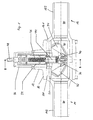
- Shut-off valve shown has a housing 100 in which two opposing spigot ends 14, 16 are disposed within an outer housing 10, the male ends 141 and 161 of each spigot 14, 16 is completely in the outer housing, while the exposed ends 142, 162 for connection existing pipelines are thought.
- a liner (insert) 20 is further provided, which lines the housing 100 in the region of the insertion ends 141, 161. Can be closed, the pipe passage 30 by means of two flaps 32, 34, which can be moved by an actuator, which will be described in more detail below, between an open position and a closed position.
- the flaps 32, 34 are articulated via a linkage mechanism 36 to a bearing body 40, which in turn carries the drive 44 for the mobility of the flaps 32, 34 from the open to the closed position and back.
- the axial movement of the drive 44 is effected by the rotational movement of the spindle 46, which is introduced via the drive square 48.
- the required number of revolutions for opening and closing the valve is determined by the pitch of the spindle 46 and the stroke required to operate the valve.
- the actuator drive 44, spindle 46 and drive square 48 is led out in a conventional manner by a departure 12 from the housing 100.
- FIG. 2 is a partially broken sectional view taken along the line BB FIG. 1 ,
- the bearing body 40 for the flaps of which only a 34 can be seen here, has two ribs 42, 42 'which are diametrically opposed to each other with respect to the actuator axis and thus form a transverse yoke.
- Each rib is guided in a groove 22 which is formed here in the insert 20, but may also be provided directly in the housing wall.
- the grooves, here only the groove 22 can be seen extending parallel to the actuator axis, so that forces resulting from the flowing through the valve medium are recorded can.
- the bearing body 40 is designed in two parts and has a carrier 41 on which the ribs 42, 42 'are preferably integrally mounted.
- the carrier 41 surrounds the suspension 43 for the closure body 32, 34, which is designed here as an external thread, which is screwed into the drive 44.
- FIG. 3 shows the situation similar in perspective view.
- the flaps are omitted in this illustration.
- the formed on the bearing body 40 rib 42 is shown here with a V-shaped outer contour, other shapes are possible.
- the spindle 46 is located within the dome 24, which consists of metal and is encapsulated with a thermoplastic material, such as polyethylene.
- the bearing of the spindle 46 via a guide plate 52 which is disposed in the upper part of the mandrel 24 near the drive square 48.
- the guide 56 of the drive 44 is done by the fit in the sleeve 24, wherein the rotation by the in the grooves 22 (FIG. FIG. 2 ) guided bearing body 40 with its ribs 42, 42 'is guaranteed.
- the upper and lower stops 60, 62 are metallic.
- the upper stop 60 is realized by a stop ring 54, the lower stop 62 by the corresponding formed bottom portion of the mandrel 24.
- the dome 24 is closed to the drive square 48 with a metallic seal 50.
- FIG. 4 shows a sectional view through the fitting, wherein the outer housing and the actuator is not shown.
- the hinged at the articulation mechanism 36 flaps 32, 34 are in their closed position. With an appropriate choice of the thickness of the flaps 32, 34 deform this at power, with the higher the pressures, the higher the deformation is. This deformation additionally assists the sealing effect of a sealing element mounted on the circumference of the flap 32, 34 due to the increased compression. Furthermore, tolerances due to the elongation of the housing 100 can thereby be compensated. The further power is absorbed, as already described, via the guided in the grooves 22 of the insert 20 ribs 42 on the bearing body 40th
Landscapes
- Engineering & Computer Science (AREA)
- General Engineering & Computer Science (AREA)
- Mechanical Engineering (AREA)
- Sealing Devices (AREA)
- Lift Valve (AREA)
- Pipe Accessories (AREA)
Description
- Die Erfindung betrifft eine Absperrarmatur, mit einem Gehäuse, das druckdicht mit einer anschließenden Rohrleitung zu verbinden ist, wobei ein Rohrdurchgang in dem Gehäuse für ein durch die Rohrleitung strömendes Medium definiert ist, und mit mindestens einem Abschlußkörper, der über einen Anlenkmechanismus mit einem vertikal zur Strömungsrichtung bewegbaren Stellantrieb aus einer Offenstellung in eine Schließstellung bewegbar ist, wobei der mindestens eine Abschlußkörper in Schließstellung mit seiner Dichtkontur radial dichtend am Rohrdurchgang anliegt. Der Anlenkmechanismus weist einen Lagerkörper auf, wobei mindestens eine Abschlußkörper lediglich an den Lagerkörper verschwenkbar angebracht ist, und wobei der Lagerkörper im Gehäuse geführt ist.
- Solche Absperrarmaturen sind aus der
WO 2003/100302 A1 bekannt. Sie bestehen in der Regel aus Metall oder Kunststoff, wobei Armaturen aus thermoplastischen Werkstoffen den Vorteil haben, daß nicht nur die einzelnen Gehäuseteile mittels bekannter Schweißverfahren stoffschlüssig gefügt werden können, es kann auch auf ebenso einfache Weise eine Anbindung an ein bestehendes PE-Rohrnetz erfolgen. Bei den in derWO 2003/100302 A1 offenbarten Absperrarmaturen ist besonders vorteilhaft, daß diese mit einem Reinigungsmolch durchfahren werden können. Dazu ist der mindestens eine Abschlußkörper so gestaltet, daß er in seiner Offenstellung außerhalb des Rohrdurchganges liegt. - Im Betriebszustand entstehen in Strömungsrichtung des Mediums Axialkräfte, die, wenn nicht vom Abschlußkörper, dann vom Stellantrieb aufgenommen werden müssen. Dabei handelt es sich einerseits um eine statische Belastung im geschlossenen Zustand der Armatur, wo einseitig wirkende Druckkräfte auftreten, andererseits aber auch um dynamische Belastungen im geöffneten Zustand bei einer Zwischenstellung des Abschlußkörpers oder der Abschlußkörper, insbesondere kurz vor dem Schließen der Armatur.
- Daher ist in der
DE 11 09 972 B vorgeschlagen worden, den Anlenkmechanismus parallel zur Bewegungsrichtung des Stellantriebes zu führen. Die Führung des Abschlußkörpers beschreibt dieUS 3 119 594 A . - Die
DE 597C betrifft ein Doppelventil, bei dem ein gehäuseseitig gelagerter Abschlusskörper über einen Stelltrieb zwischen einer Offen- und einer Schließstellung bewegbar ist, und wobei eine sowohl mit den Schließkörpern als auch dem Stelltrieb in Verbindung stehende Mutter über Führungsarme verfügt, welche in gehäuseseitige Nuten eingreifen und somit ein Verdrehen der Mutter A entlang der Stelltriebachse verhindert wird. - Die
US 3,119,594 sowieUS 3,632,080 offenbaren jeweils eine Absperrarmatur, bei der der Abschlusskörper sowohl gehäuseseitig als auch über eine Achse, welche in ein Langloch des Abschlusskörpers eingreift, gelagert ist. - Es ist die Aufgabe der Erfindung, eine Absperrarmatur zur Verfügung zu stellen, bei der die oben beschriebenen Axialkräfte auf einfache Weise innerhalb der Armatur noch besser neutralisiert werden.
- Diese Aufgabe wird bei einer Absperrarmatur der eingangs genannten Gattung dadurch gelöst, daß der Lagerkörper zwei diametral gegenüberstehende Rippen aufweist und in der Wand des Gehäuses oder in einer das Gehäuse zumindest teilweise auskleidenden Einlage entsprechend zwei Nuten ausgebildet sind, wobei die Rippen ein sich quer zur Strömungsrichtung des Mediums erstreckendes Joch bilden. Dies bedeutet, daß die Querbelastung auf den Stellantrieb unter einseitiger Belastung abgefangen und die Betriebssicherheit der Armatur auch bei Zwischenstellungen des Abschlußkörpers gewährleistet ist. Es bildet der Lagerkörper ein Querjoch, mit dem die Axialkräfte gleichmäßig in das Gehäuse weitergeleitet werden können.
- Das Gehäuse weist vorteilhaft eine Einlage (Insert) auf, in der die mindestens eine Nut ausgebildet ist, so daß eine problemlose Vorfertigung möglich wird.
- Der Lagerkörper weist nach einer bevorzugten Ausgestaltung einen Träger auf, von dem die mindestens eine Rippe hervorsteht, wobei der Träger die Aufhängung für den mindestens einen Abschlußkörper umgibt. Das heißt, daß der Lagerkörper zweiteilig ausgebildet sein kann, wobei weiter bevorzugt die Aufhängung ein Außengewinde zum Einschrauben in den Antrieb aufweist. Die zweiteilige Ausgestaltung macht es möglich, daß die durch das strömende Medium hervorgegangenen Kräfte optimal aufgefangen werden.
- Weiter vorteilhaft ist der mindestens eine Abschlußkörper als Klappe ausgebildet; die sich bei im wesentlichen axialer Druckbeaufschlagung durch das strömende Medium an ihrer Dichtkontur aufweitet. Der Abschlußkörper bzw. die Klappe wird mit verformt, wobei diese Verformung zusätzlich die Dichtwirkung des an der Dichtkontur vorzugsweise angebrachten Dichtelementes durch erhöhte Verpressung unterstützt. Auch können dadurch Toleranzen aufgrund der Dehnung des Gehäuses aufgefangen werden; es handelt sich erfindungsgemäß um eine selbstnachdichtende Klappe.
- Im folgenden soll die Erfindung lediglich beispielhaft anhand der beigefügten Zeichnung näher erläutert werden. Es zeigt:
- Figur 1
- eine Längsschnittansicht durch eine Ausführungsform einer Absperrarmatur gemäß der vorliegenden Erfindung;
- Figur 2
- eine Schnittansicht entlang der Linie B-B aus
Figur 1 ; - Figur 3
- eine perspektivische Ansicht eines Stellantriebs mit einem Lagerkörper gemäß der vorliegenden Erfindung; und
- Figur 4
- eine Ansicht der Absperrarmatur, aus der die Lage der Nut besonders deutlich hervorgeht; und
- Die in
Figur 1 dargestellte Absperrarmatur weist ein Gehäuse 100 auf, bei dem innerhalb eines Außengehäuses 10 zwei gegenüberstehende Spitzenden 14, 16 angeordnet sind, die Einsteckenden 141 und 161 jedes Spitzendes 14, 16 befindet sich dabei vollständig im Außengehäuse, während die freiliegenden Enden 142, 162 zum Anschluß an bestehende Rohrleitungen gedacht sind. Innerhalb des Gehäuses 100 ist weiterhin eine Einlage (Insert) 20 vorgesehen, welches das Gehäuse 100 im Bereich der Einsteckenden 141, 161 auskleidet. Verschlossen werden kann der Rohrdurchgang 30 mittels zweier Klappen 32, 34, die über einen Stellantrieb, der im folgenden noch näher beschrieben wird, zwischen einer Offenstellung und einer Schließstellung verfahren werden können. Die Klappen 32, 34 sind dabei über einen Anlenkmechanismus 36 an einem Lagerkörper 40 angelenkt, der wiederum den Antrieb 44 für die Verfahrbarkeit der Klappen 32, 34 aus der Offen- in die Schließstellung und zurück trägt. Die Axialbewegung des Antriebes 44 erfolgt durch die Drehbewegung der Spindel 46, welche über den Antriebsvierkant 48 eingeleitet wird. Die erforderliche Umdrehungszahl zum Öffnen und Schließen der Armatur wird über die Steigung der Spindel 46 und den erforderlichen Hub zum Betätigen der Armatur bestimmt. Der Stellantrieb aus Antrieb 44, Spindel 46 und Antriebsvierkant 48 ist auf übliche Weise durch einen Abgang 12 aus dem Gehäuse 100 herausgeführt. -
Figur 2 ist eine teilweise weggebrochene Schnittansicht entlang der Linie B-B ausFigur 1 . Der Lagerkörper 40 für die Klappen, von denen hier nur eine 34 zu sehen ist, weist zwei Rippen 42, 42' auf, die einander in bezug auf die Stellantriebsachse diametral gegenüberstehen und somit ein Querjoch bilden. Jede Rippe ist in einer Nut 22 geführt, die hier in der Einlage 20 ausgebildet ist, aber auch direkt in der Gehäusewand vorgesehen sein kann. Die Nuten, hier ist nur die Nut 22 zu sehen, erstrecken sich parallel zur Stellantriebsachse, so daß Kräfte, die sich durch das durch die Armatur strömende Medium ergeben, aufgenommen werden können. Der Lagerkörper 40 ist zweiteilig ausgestaltet und weist einen Träger 41 auf, an dem die Rippen 42, 42' bevorzugt einstückig angebracht sind. Der Träger 41 umgibt dabei die Aufhängung 43 für die Abschlußkörper 32, 34, die hier als Außengewinde ausgestaltet ist, welches in den Antrieb 44 eingeschraubt wird. -
Figur 3 zeigt die Situation ähnlich in perspektivischer Ansicht. Aus Gründen der Klarheit sind die Klappen in dieser Darstellung weggelassen. Die auf dem Lagerkörper 40 ausgebildete Rippe 42 ist hier mit V-förmiger Außenkontur dargestellt, andere Formgebungen sind jedoch möglich. DerFigur 3 sind auch weitere Einzelheiten über den Stellantrieb zu entnehmen. Die Spindel 46 befindet sich dabei innerhalb des Doms 24, der aus Metall besteht und mit einem thermoplastischen Kunststoff, beispielsweise Polyethylen umspritzt ist. Die Lagerung der Spindel 46 erfolgt über eine Führungsscheibe 52, die im oberen Teil des Doms 24 nahe dem Antriebsvierkant 48 angeordnet ist. Die Führung 56 des Antriebs 44 geschieht durch die Passung in der Hülse 24, wobei die Verdrehsicherung durch den in den Nuten 22 (Figur 2 ) geführten Lagerkörper 40 mit seinen Rippen 42, 42'gewährleistet ist. Der obere und der untere Anschlag 60, 62 sind metallisch. Der obere Anschlag 60 wird durch einen Anschlagring 54, der untere Anschlag 62 durch den entsprechenden ausgebildeten Bodenbereich des Doms 24 realisiert. Der Dom 24 ist zum Antriebsvierkant 48 hin mit einer metallischen Abdichtung 50 verschlossen. -
Figur 4 zeigt eine Schnittansicht durch die Armatur, wobei Außengehäuse und der Stellantrieb nicht dargestellt ist. Die am Anlenkmechanismus 36 angelenkten Klappen 32, 34 befinden sich in ihrer Schließstellung. Bei entsprechender Wahl der Dicke der Klappen 32, 34 verformen diese sich bei Kraftaufnahme, wobei je höher die Drücke sind, um so höher auch die Verformung ist. Diese Verformung unterstützt zusätzlich die Dichtwirkung eines auf dem Umfang der Klappe 32, 34 angebrachten Dichtelementes durch die erhöhte Verpressung. Des weiteren können dadurch Toleranzen aufgrund der Dehnung des Gehäuses 100 aufgefangen werden. Die weitere Kraftaufnahme geschieht, wie schon geschildert, über die in den Nuten 22 der Einlage 20 geführten Rippen 42 am Lagerkörper 40. - Die in der vorstehenden Beschreibung, in der Zeichnung sowie in den Ansprüchen offenbarten Merkmale der Erfindung können sowohl einzeln als auch in beliebiger Kombination für die Verwirklichung der Erfindung wesentlich sein.
Claims (6)
- Absperrarmatur, mit einem Gehäuse (100), das druckdicht mit einer anschließenden Rohrleitung zu verbinden ist, wobei ein Rohrdurchgang (30) in dem Gehäuse (100) für ein durch die Rohrleitung strömendes Medium definiert ist, und mit mindestens einem Abschlusskörper (32, 34), der über einen Anlenkmechanismus (36, 40) mit einem vertikal zur Strömungsrichtung bewegbaren Stellantrieb (44, 46, 48) aus einer Offenstellung in eine Schließstellung, in der der mindestens eine Abschlusskörper (32, 34) mit seiner Dichtkontur radial dichtend am Rohrdurchgang anliegt, bewegbar ist, wobei der Anlenkmechanismus (36, 40) parallel zur Bewegungsrichtung des Stellantriebes (44, 46, 48) geführt ist und einen Lagerkörper (40) aufweist, wobei der mindestens eine Abschlusskörper (32, 34) lediglich an dem Lagerkörper (40) verschwenkbar angebracht ist,
dadurch gekennzeichnet, dass der Lagerkörper (40) zwei diametral gegenüberstehende Rippen (42, 42') aufweist und in der Wand des Gehäuses (100) oder in einer das Gehäuse (1200) zumindest teilweise auskleidenden Einlage (20) entsprechend zwei Nuten (22) ausgebildet sind, wobei die Rippen (42) ein sich quer zur Strömungsrichtung des Mediums erstreckendes Joch bilden. - Absperrarmatur nach Anspruch 1, dadurch gekennzeichnet, dass der Lagerkörper (40) einen Träger (41) aufweist, von dem die Rippen (42, 42') hervorsteht, wobei der Träger (41) die Aufhängung (43) für den mindestens einen Abschlusskörper (32, 34) umgibt.
- Absperrarmatur nach Anspruch 2, dadurch gekennzeichnet, dass die Aufhängung (43) ein Außengewinde zum Einschrauben in den Antrieb (44) aufweist.
- Absperrarmatur nach einem der Ansprüche 1 bis 3, dadurch gekennzeichnet, dass der mindestens eine Abschlusskörper (32, 34) als Klappe ausgebildet ist.
- Absperrarmatur nach einem der Ansprüche 1 bis 4, dadurch gekennzeichnet, dass der mindestens eine Abschlusskörper (32, 34) sich bei im wesentlichen axialer Druckbeaufschlagung durch das strömende Medium an seiner Dichtkontur aufweitet.
- Absperrarmatur nach einem der Ansprüche 1 bis 5, dadurch gekennzeichnet, dass an der Dichtkontur des mindestens einen Abschlusskörpers (32, 34) ein Dichtelement angebracht ist.
Applications Claiming Priority (2)
| Application Number | Priority Date | Filing Date | Title |
|---|---|---|---|
| DE102006030027A DE102006030027A1 (de) | 2006-06-29 | 2006-06-29 | Absperrarmatur |
| PCT/DE2007/001117 WO2008000233A1 (de) | 2006-06-29 | 2007-06-25 | Absperrarmatur |
Publications (2)
| Publication Number | Publication Date |
|---|---|
| EP2054649A1 EP2054649A1 (de) | 2009-05-06 |
| EP2054649B1 true EP2054649B1 (de) | 2014-01-22 |
Family
ID=38686829
Family Applications (1)
| Application Number | Title | Priority Date | Filing Date |
|---|---|---|---|
| EP20070785550 Active EP2054649B1 (de) | 2006-06-29 | 2007-06-25 | Absperrarmatur |
Country Status (6)
| Country | Link |
|---|---|
| US (1) | US8181934B2 (de) |
| EP (1) | EP2054649B1 (de) |
| CN (1) | CN101479511B (de) |
| DE (1) | DE102006030027A1 (de) |
| IL (1) | IL196249A (de) |
| WO (1) | WO2008000233A1 (de) |
Families Citing this family (3)
| Publication number | Priority date | Publication date | Assignee | Title |
|---|---|---|---|---|
| DE102008054103A1 (de) | 2008-10-31 | 2010-05-06 | Friatec Aktiengesellschaft | Bauelement für Anwendungen im Brauch- und/oder Abwasserbereich und Absperrarmatur mit einem derartigen Bauelement |
| DE102016200396B3 (de) | 2016-01-14 | 2016-08-25 | Festo Ag & Co. Kg | Ventilbetätigungssystem |
| US10563774B2 (en) | 2017-06-30 | 2020-02-18 | Intelligent Agricultural Solutions Llc | Sectional control device |
Family Cites Families (13)
| Publication number | Priority date | Publication date | Assignee | Title |
|---|---|---|---|---|
| DE597C (de) * | 1877-08-08 | A. VOGELSANG in Sprockhövel, Kreis Hagen | Zwei Ausführungen eines Doppelventils | |
| US1949011A (en) * | 1932-11-17 | 1934-02-27 | John T Fahey | Gate valve |
| US2831498A (en) * | 1955-03-17 | 1958-04-22 | Specialties Dev Corp | Direction valve |
| FR1141242A (fr) * | 1956-02-10 | 1957-08-28 | Louis Jalet Ets | Dispositif d'étanchéité pour sectionnements |
| DE1109972B (de) * | 1959-03-16 | 1961-06-29 | Williamson Inc T | Absperrvorrichtung fuer eine Leitung mit einem Verschlussstueck, das an einem Schlitten angelenkt ist |
| US3119594A (en) * | 1961-02-17 | 1964-01-28 | Orbit Valve Co | Swing gate valve |
| US3632080A (en) * | 1969-05-12 | 1972-01-04 | Louis T King | Pressure-balanced flapper valve |
| FR2053800A5 (de) * | 1969-07-18 | 1971-04-16 | Pont A Mousson | |
| US3586034A (en) * | 1970-01-29 | 1971-06-22 | Michael P Karzeniowski | Automatic draining and locking fluid valve |
| US3913603A (en) * | 1974-01-14 | 1975-10-21 | Purolator Inc | Crashworthy flapper valve |
| US3876179A (en) * | 1974-04-01 | 1975-04-08 | Hans D Baumann | Eccentric rotary plug valve with quick removal trim insert |
| IL96766A (en) * | 1990-12-23 | 1994-07-31 | Feldinger Edgar | Control valve |
| ATE401517T1 (de) * | 2002-05-23 | 2008-08-15 | Friatec Ag | Absperrarmatur |
-
2006
- 2006-06-29 DE DE102006030027A patent/DE102006030027A1/de not_active Ceased
-
2007
- 2007-06-25 US US12/306,231 patent/US8181934B2/en not_active Expired - Fee Related
- 2007-06-25 EP EP20070785550 patent/EP2054649B1/de active Active
- 2007-06-25 CN CN2007800243707A patent/CN101479511B/zh not_active Expired - Fee Related
- 2007-06-25 WO PCT/DE2007/001117 patent/WO2008000233A1/de not_active Ceased
-
2008
- 2008-12-29 IL IL196249A patent/IL196249A/en not_active IP Right Cessation
Also Published As
| Publication number | Publication date |
|---|---|
| US8181934B2 (en) | 2012-05-22 |
| US20090294718A1 (en) | 2009-12-03 |
| IL196249A (en) | 2014-06-30 |
| IL196249A0 (en) | 2009-09-22 |
| DE102006030027A1 (de) | 2008-01-03 |
| EP2054649A1 (de) | 2009-05-06 |
| WO2008000233A1 (de) | 2008-01-03 |
| CN101479511B (zh) | 2011-05-25 |
| CN101479511A (zh) | 2009-07-08 |
Similar Documents
| Publication | Publication Date | Title |
|---|---|---|
| EP1506361B1 (de) | Absperrarmatur | |
| EP2529136B1 (de) | Absperrhahn für den installationsbereich | |
| EP1688654B1 (de) | Vakuumventil | |
| EP0968382B1 (de) | Sitzreinigungsfähiges doppelsitzventil | |
| DE2728192A1 (de) | Zerbrechliches schlauchend-fitting | |
| DE10234482B3 (de) | Vorrichtung zum Antrieb für Doppelsitzventile | |
| DE102008010249A1 (de) | Antriebseinrichtung | |
| DE102008010347A1 (de) | Verteilerventil mit integrierter Durchflussmesseinrichtung | |
| DE2047266A1 (de) | Dichtungs und Lagereinrichtung fur Ventile | |
| DE102017120003A1 (de) | Luftausströmer für ein Fahrzeug | |
| WO2014128118A2 (de) | Kolben-zylinder-einheit | |
| EP2054649A1 (de) | Absperrarmatur | |
| DE69616296T2 (de) | Armaturvorrichtung | |
| EP2699510B1 (de) | Flüssigkeitsventil | |
| DE7537694U (de) | Fluessigkeitsventil | |
| EP3369972B1 (de) | Scheibenventil | |
| WO1993022587A1 (de) | Klappenachsenabdichtung | |
| WO2007033693A1 (de) | Kupplungseinrichtung zum verbinden von leitungseinrichtungen, vorzugsweise quick connector | |
| DE202018105534U1 (de) | Ventil | |
| DE2820168A1 (de) | Rohrleitungsschalter | |
| DE19740674C2 (de) | Blasenförmige Membran | |
| EP3236121A1 (de) | Wechselventil für eine sicherheitsventilanordnung und sicherheitsventilanordnung | |
| EP1926929B1 (de) | Ventilvorrichtung | |
| DE2308453C3 (de) | Ventil zur temperaturabhängigen Steuerung eines gasförmigen oder flüssigen Mediums | |
| DE19916705C1 (de) | Absperrarmatur und Verfahren zu ihrer Herstellung |
Legal Events
| Date | Code | Title | Description |
|---|---|---|---|
| PUAI | Public reference made under article 153(3) epc to a published international application that has entered the european phase |
Free format text: ORIGINAL CODE: 0009012 |
|
| 17P | Request for examination filed |
Effective date: 20081219 |
|
| AK | Designated contracting states |
Kind code of ref document: A1 Designated state(s): AT BE BG CH CY CZ DE DK EE ES FI FR GB GR HU IE IS IT LI LT LU LV MC MT NL PL PT RO SE SI SK TR |
|
| AX | Request for extension of the european patent |
Extension state: AL BA HR MK RS |
|
| RIN1 | Information on inventor provided before grant (corrected) |
Inventor name: MAIER, FABIAN Inventor name: GEHR, HEIKO Inventor name: SICHLER, WOLFGANG Inventor name: ROTHERMEL, ALEXANDER Inventor name: SCHMICH, RALF Inventor name: SCHNEIDER, MICHAEL Inventor name: SCHMITT, HARALD Inventor name: SCHWARZ, SIMON Inventor name: ELSASSER, DIRK |
|
| 17Q | First examination report despatched |
Effective date: 20090812 |
|
| DAX | Request for extension of the european patent (deleted) | ||
| REG | Reference to a national code |
Ref country code: DE Ref legal event code: R079 Ref document number: 502007012732 Country of ref document: DE Free format text: PREVIOUS MAIN CLASS: F16K0001160000 Ipc: F16K0031520000 |
|
| RIC1 | Information provided on ipc code assigned before grant |
Ipc: F16K 1/16 20060101ALI20130627BHEP Ipc: F16K 31/52 20060101AFI20130627BHEP Ipc: F16K 31/50 20060101ALI20130627BHEP |
|
| GRAP | Despatch of communication of intention to grant a patent |
Free format text: ORIGINAL CODE: EPIDOSNIGR1 |
|
| INTG | Intention to grant announced |
Effective date: 20130821 |
|
| GRAS | Grant fee paid |
Free format text: ORIGINAL CODE: EPIDOSNIGR3 |
|
| GRAA | (expected) grant |
Free format text: ORIGINAL CODE: 0009210 |
|
| AK | Designated contracting states |
Kind code of ref document: B1 Designated state(s): AT BE BG CH CY CZ DE DK EE ES FI FR GB GR HU IE IS IT LI LT LU LV MC MT NL PL PT RO SE SI SK TR |
|
| REG | Reference to a national code |
Ref country code: GB Ref legal event code: FG4D Free format text: NOT ENGLISH |
|
| REG | Reference to a national code |
Ref country code: CH Ref legal event code: EP |
|
| REG | Reference to a national code |
Ref country code: AT Ref legal event code: REF Ref document number: 650969 Country of ref document: AT Kind code of ref document: T Effective date: 20140215 |
|
| REG | Reference to a national code |
Ref country code: IE Ref legal event code: FG4D Free format text: LANGUAGE OF EP DOCUMENT: GERMAN |
|
| REG | Reference to a national code |
Ref country code: DE Ref legal event code: R096 Ref document number: 502007012732 Country of ref document: DE Effective date: 20140306 |
|
| REG | Reference to a national code |
Ref country code: NL Ref legal event code: VDEP Effective date: 20140122 |
|
| REG | Reference to a national code |
Ref country code: CH Ref legal event code: NV Representative=s name: KAMINSKI HARMANN PATENTANWAELTE AG, LI |
|
| REG | Reference to a national code |
Ref country code: LT Ref legal event code: MG4D |
|
| PG25 | Lapsed in a contracting state [announced via postgrant information from national office to epo] |
Ref country code: LT Free format text: LAPSE BECAUSE OF FAILURE TO SUBMIT A TRANSLATION OF THE DESCRIPTION OR TO PAY THE FEE WITHIN THE PRESCRIBED TIME-LIMIT Effective date: 20140122 Ref country code: IS Free format text: LAPSE BECAUSE OF FAILURE TO SUBMIT A TRANSLATION OF THE DESCRIPTION OR TO PAY THE FEE WITHIN THE PRESCRIBED TIME-LIMIT Effective date: 20140522 |
|
| PG25 | Lapsed in a contracting state [announced via postgrant information from national office to epo] |
Ref country code: CY Free format text: LAPSE BECAUSE OF FAILURE TO SUBMIT A TRANSLATION OF THE DESCRIPTION OR TO PAY THE FEE WITHIN THE PRESCRIBED TIME-LIMIT Effective date: 20140122 Ref country code: ES Free format text: LAPSE BECAUSE OF FAILURE TO SUBMIT A TRANSLATION OF THE DESCRIPTION OR TO PAY THE FEE WITHIN THE PRESCRIBED TIME-LIMIT Effective date: 20140122 Ref country code: FI Free format text: LAPSE BECAUSE OF FAILURE TO SUBMIT A TRANSLATION OF THE DESCRIPTION OR TO PAY THE FEE WITHIN THE PRESCRIBED TIME-LIMIT Effective date: 20140122 Ref country code: PT Free format text: LAPSE BECAUSE OF FAILURE TO SUBMIT A TRANSLATION OF THE DESCRIPTION OR TO PAY THE FEE WITHIN THE PRESCRIBED TIME-LIMIT Effective date: 20140522 Ref country code: SE Free format text: LAPSE BECAUSE OF FAILURE TO SUBMIT A TRANSLATION OF THE DESCRIPTION OR TO PAY THE FEE WITHIN THE PRESCRIBED TIME-LIMIT Effective date: 20140122 Ref country code: NL Free format text: LAPSE BECAUSE OF FAILURE TO SUBMIT A TRANSLATION OF THE DESCRIPTION OR TO PAY THE FEE WITHIN THE PRESCRIBED TIME-LIMIT Effective date: 20140122 |
|
| PG25 | Lapsed in a contracting state [announced via postgrant information from national office to epo] |
Ref country code: LV Free format text: LAPSE BECAUSE OF FAILURE TO SUBMIT A TRANSLATION OF THE DESCRIPTION OR TO PAY THE FEE WITHIN THE PRESCRIBED TIME-LIMIT Effective date: 20140122 |
|
| REG | Reference to a national code |
Ref country code: DE Ref legal event code: R097 Ref document number: 502007012732 Country of ref document: DE |
|
| PG25 | Lapsed in a contracting state [announced via postgrant information from national office to epo] |
Ref country code: RO Free format text: LAPSE BECAUSE OF FAILURE TO SUBMIT A TRANSLATION OF THE DESCRIPTION OR TO PAY THE FEE WITHIN THE PRESCRIBED TIME-LIMIT Effective date: 20140122 Ref country code: CZ Free format text: LAPSE BECAUSE OF FAILURE TO SUBMIT A TRANSLATION OF THE DESCRIPTION OR TO PAY THE FEE WITHIN THE PRESCRIBED TIME-LIMIT Effective date: 20140122 Ref country code: DK Free format text: LAPSE BECAUSE OF FAILURE TO SUBMIT A TRANSLATION OF THE DESCRIPTION OR TO PAY THE FEE WITHIN THE PRESCRIBED TIME-LIMIT Effective date: 20140122 Ref country code: EE Free format text: LAPSE BECAUSE OF FAILURE TO SUBMIT A TRANSLATION OF THE DESCRIPTION OR TO PAY THE FEE WITHIN THE PRESCRIBED TIME-LIMIT Effective date: 20140122 |
|
| PG25 | Lapsed in a contracting state [announced via postgrant information from national office to epo] |
Ref country code: PL Free format text: LAPSE BECAUSE OF FAILURE TO SUBMIT A TRANSLATION OF THE DESCRIPTION OR TO PAY THE FEE WITHIN THE PRESCRIBED TIME-LIMIT Effective date: 20140122 Ref country code: SK Free format text: LAPSE BECAUSE OF FAILURE TO SUBMIT A TRANSLATION OF THE DESCRIPTION OR TO PAY THE FEE WITHIN THE PRESCRIBED TIME-LIMIT Effective date: 20140122 |
|
| PLBE | No opposition filed within time limit |
Free format text: ORIGINAL CODE: 0009261 |
|
| STAA | Information on the status of an ep patent application or granted ep patent |
Free format text: STATUS: NO OPPOSITION FILED WITHIN TIME LIMIT |
|
| 26N | No opposition filed |
Effective date: 20141023 |
|
| PG25 | Lapsed in a contracting state [announced via postgrant information from national office to epo] |
Ref country code: LU Free format text: LAPSE BECAUSE OF FAILURE TO SUBMIT A TRANSLATION OF THE DESCRIPTION OR TO PAY THE FEE WITHIN THE PRESCRIBED TIME-LIMIT Effective date: 20140625 Ref country code: MC Free format text: LAPSE BECAUSE OF FAILURE TO SUBMIT A TRANSLATION OF THE DESCRIPTION OR TO PAY THE FEE WITHIN THE PRESCRIBED TIME-LIMIT Effective date: 20140122 |
|
| REG | Reference to a national code |
Ref country code: DE Ref legal event code: R097 Ref document number: 502007012732 Country of ref document: DE Effective date: 20141023 |
|
| GBPC | Gb: european patent ceased through non-payment of renewal fee |
Effective date: 20140625 |
|
| REG | Reference to a national code |
Ref country code: IE Ref legal event code: MM4A |
|
| REG | Reference to a national code |
Ref country code: FR Ref legal event code: ST Effective date: 20150227 |
|
| PG25 | Lapsed in a contracting state [announced via postgrant information from national office to epo] |
Ref country code: IE Free format text: LAPSE BECAUSE OF NON-PAYMENT OF DUE FEES Effective date: 20140625 |
|
| PG25 | Lapsed in a contracting state [announced via postgrant information from national office to epo] |
Ref country code: GB Free format text: LAPSE BECAUSE OF NON-PAYMENT OF DUE FEES Effective date: 20140625 Ref country code: SI Free format text: LAPSE BECAUSE OF FAILURE TO SUBMIT A TRANSLATION OF THE DESCRIPTION OR TO PAY THE FEE WITHIN THE PRESCRIBED TIME-LIMIT Effective date: 20140122 Ref country code: FR Free format text: LAPSE BECAUSE OF NON-PAYMENT OF DUE FEES Effective date: 20140630 |
|
| PG25 | Lapsed in a contracting state [announced via postgrant information from national office to epo] |
Ref country code: MT Free format text: LAPSE BECAUSE OF FAILURE TO SUBMIT A TRANSLATION OF THE DESCRIPTION OR TO PAY THE FEE WITHIN THE PRESCRIBED TIME-LIMIT Effective date: 20140122 |
|
| PG25 | Lapsed in a contracting state [announced via postgrant information from national office to epo] |
Ref country code: BG Free format text: LAPSE BECAUSE OF FAILURE TO SUBMIT A TRANSLATION OF THE DESCRIPTION OR TO PAY THE FEE WITHIN THE PRESCRIBED TIME-LIMIT Effective date: 20140122 |
|
| PG25 | Lapsed in a contracting state [announced via postgrant information from national office to epo] |
Ref country code: GR Free format text: LAPSE BECAUSE OF FAILURE TO SUBMIT A TRANSLATION OF THE DESCRIPTION OR TO PAY THE FEE WITHIN THE PRESCRIBED TIME-LIMIT Effective date: 20140423 Ref country code: IT Free format text: LAPSE BECAUSE OF FAILURE TO SUBMIT A TRANSLATION OF THE DESCRIPTION OR TO PAY THE FEE WITHIN THE PRESCRIBED TIME-LIMIT Effective date: 20140122 |
|
| PG25 | Lapsed in a contracting state [announced via postgrant information from national office to epo] |
Ref country code: TR Free format text: LAPSE BECAUSE OF FAILURE TO SUBMIT A TRANSLATION OF THE DESCRIPTION OR TO PAY THE FEE WITHIN THE PRESCRIBED TIME-LIMIT Effective date: 20140122 Ref country code: HU Free format text: LAPSE BECAUSE OF FAILURE TO SUBMIT A TRANSLATION OF THE DESCRIPTION OR TO PAY THE FEE WITHIN THE PRESCRIBED TIME-LIMIT; INVALID AB INITIO Effective date: 20070625 Ref country code: BE Free format text: LAPSE BECAUSE OF FAILURE TO SUBMIT A TRANSLATION OF THE DESCRIPTION OR TO PAY THE FEE WITHIN THE PRESCRIBED TIME-LIMIT Effective date: 20140630 |
|
| REG | Reference to a national code |
Ref country code: DE Ref legal event code: R082 Ref document number: 502007012732 Country of ref document: DE Representative=s name: 24IP LAW GROUP SONNENBERG FORTMANN, DE Ref country code: DE Ref legal event code: R081 Ref document number: 502007012732 Country of ref document: DE Owner name: ALIAXIS DEUTSCHLAND GMBH, DE Free format text: FORMER OWNER: FRIATEC AG, 68229 MANNHEIM, DE Ref country code: DE Ref legal event code: R082 Ref document number: 502007012732 Country of ref document: DE Representative=s name: SONNENBERG HARRISON PARTNERSCHAFT MBB, DE Ref country code: DE Ref legal event code: R082 Ref document number: 502007012732 Country of ref document: DE Representative=s name: BOEHMERT & BOEHMERT ANWALTSPARTNERSCHAFT MBB -, DE Ref country code: DE Ref legal event code: R081 Ref document number: 502007012732 Country of ref document: DE Owner name: FRIATEC GMBH, DE Free format text: FORMER OWNER: FRIATEC AG, 68229 MANNHEIM, DE |
|
| REG | Reference to a national code |
Ref country code: DE Ref legal event code: R082 Ref document number: 502007012732 Country of ref document: DE Representative=s name: 24IP LAW GROUP SONNENBERG FORTMANN, DE Ref country code: DE Ref legal event code: R082 Ref document number: 502007012732 Country of ref document: DE Representative=s name: SONNENBERG HARRISON PARTNERSCHAFT MBB, DE Ref country code: DE Ref legal event code: R082 Ref document number: 502007012732 Country of ref document: DE Representative=s name: SONNENBERG HARRISON PARTNERSCHAFT MBB PATENT- , DE |
|
| REG | Reference to a national code |
Ref country code: CH Ref legal event code: NV Representative=s name: 24IP LAW GROUP SONNENBERG FORTMANN, CH |
|
| REG | Reference to a national code |
Ref country code: CH Ref legal event code: NV Representative=s name: BOVARD SA NEUCHATEL CONSEILS EN PROPRETE INTEL, CH Ref country code: CH Ref legal event code: PFA Owner name: FRIATEC GMBH, DE Free format text: FORMER OWNER: FRIATEC AKTIENGESELLSCHAFT, DE |
|
| REG | Reference to a national code |
Ref country code: CH Ref legal event code: NV Representative=s name: 24IP LAW GROUP SONNENBERG FORTMANN, CH |
|
| REG | Reference to a national code |
Ref country code: AT Ref legal event code: PC Ref document number: 650969 Country of ref document: AT Kind code of ref document: T Owner name: FRIATEC GMBH, DE Effective date: 20190612 |
|
| REG | Reference to a national code |
Ref country code: CH Ref legal event code: PFA Owner name: ALIAXIS DEUTSCHLAND GMBH, DE Free format text: FORMER OWNER: FRIATEC GMBH, DE |
|
| REG | Reference to a national code |
Ref country code: DE Ref legal event code: R082 Ref document number: 502007012732 Country of ref document: DE Representative=s name: 24IP LAW GROUP SONNENBERG FORTMANN, DE Ref country code: DE Ref legal event code: R081 Ref document number: 502007012732 Country of ref document: DE Owner name: ALIAXIS DEUTSCHLAND GMBH, DE Free format text: FORMER OWNER: FRIATEC GMBH, 68229 MANNHEIM, DE Ref country code: DE Ref legal event code: R082 Ref document number: 502007012732 Country of ref document: DE Representative=s name: SONNENBERG HARRISON PARTNERSCHAFT MBB, DE |
|
| REG | Reference to a national code |
Ref country code: AT Ref legal event code: HC Ref document number: 650969 Country of ref document: AT Kind code of ref document: T Owner name: ALIAXIS DEUTSCHLAND GMBH, DE Effective date: 20200723 |
|
| REG | Reference to a national code |
Ref country code: DE Ref legal event code: R082 Ref document number: 502007012732 Country of ref document: DE Representative=s name: SONNENBERG HARRISON PARTNERSCHAFT MBB, DE Ref country code: DE Ref legal event code: R082 Ref document number: 502007012732 Country of ref document: DE Representative=s name: SONNENBERG HARRISON PARTNERSCHAFT MBB PATENT- , DE |
|
| PGFP | Annual fee paid to national office [announced via postgrant information from national office to epo] |
Ref country code: DE Payment date: 20220621 Year of fee payment: 16 |
|
| PGFP | Annual fee paid to national office [announced via postgrant information from national office to epo] |
Ref country code: AT Payment date: 20220617 Year of fee payment: 16 |
|
| PGFP | Annual fee paid to national office [announced via postgrant information from national office to epo] |
Ref country code: CH Payment date: 20220629 Year of fee payment: 16 |
|
| P01 | Opt-out of the competence of the unified patent court (upc) registered |
Effective date: 20230801 |
|
| REG | Reference to a national code |
Ref country code: DE Ref legal event code: R119 Ref document number: 502007012732 Country of ref document: DE |
|
| REG | Reference to a national code |
Ref country code: CH Ref legal event code: PL |
|
| REG | Reference to a national code |
Ref country code: AT Ref legal event code: MM01 Ref document number: 650969 Country of ref document: AT Kind code of ref document: T Effective date: 20230625 |
|
| PG25 | Lapsed in a contracting state [announced via postgrant information from national office to epo] |
Ref country code: AT Free format text: LAPSE BECAUSE OF NON-PAYMENT OF DUE FEES Effective date: 20230625 |
|
| PG25 | Lapsed in a contracting state [announced via postgrant information from national office to epo] |
Ref country code: DE Free format text: LAPSE BECAUSE OF NON-PAYMENT OF DUE FEES Effective date: 20240103 Ref country code: AT Free format text: LAPSE BECAUSE OF NON-PAYMENT OF DUE FEES Effective date: 20230625 Ref country code: CH Free format text: LAPSE BECAUSE OF NON-PAYMENT OF DUE FEES Effective date: 20230630 |